Embed Size (px)
Citation preview
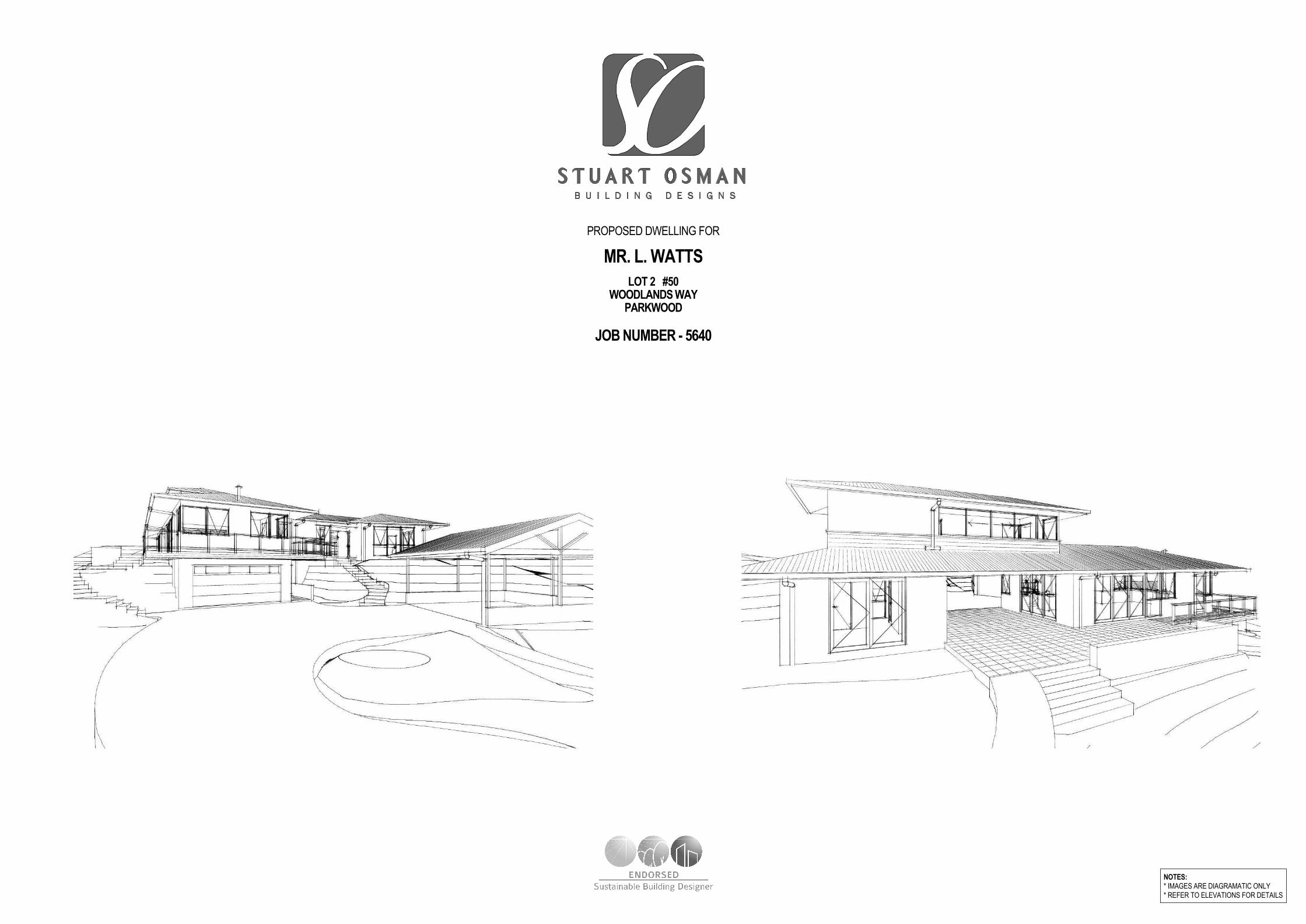
MR. L. WATTS
LOT 2 #50WOODLANDS WAY
PARKWOOD
JOB NUMBER - 5640
NOTES:* IMAGES ARE DIAGRAMATIC ONLY
* REFER TO ELEVATIONS FOR DETAILS
PROPOSED DWELLING FOR

Phone (07) 55 203 022
Fax (07) 55 203 033PO Box 2845 Burleigh Heads DC Qld 4220
Address: 2/71 Township Drive, West Burleigh, QLD 4219ABN 73 097 995 616
BSA License No: 1129687Email: [email protected]
© Copyright reserved in part or whole. Writtendimensions take preference.
Contractor to verify dimensions.Notify designers of discrepancies.
Failure to do so shall voidthe designers responsibilities.
THIS
DE
SIG
N IS
TH
E E
XC
LUS
IVE
PR
OP
ER
TY
OF
ST
UA
RT
OS
MA
N B
UIL
DIN
G D
ES
IGN
SN
.B A
LL W
RIT
TE
N D
IME
NS
ION
S T
AK
E P
RE
CE
DE
NC
E O
VE
R S
CA
LED
SIZ
ES
BE
WA
RN
ED
: SU
BS
TIT
UT
ION
OF
AN
Y S
TR
UC
TU
RA
L M
EM
BE
RS
, AN
D O
R A
NY
VA
RIA
TIO
N T
O A
NY
PA
RT
OF
TH
E D
ES
IGN
WIL
L V
OID
AN
YR
ES
PO
NS
IBIL
ITIE
S O
F S
TU
AR
T O
SM
AN
BU
ILD
ING
DE
SIG
NS
FO
R T
HE
ST
RU
CT
UR
AL
INT
EG
RIT
Y A
ND
PE
RF
OR
MA
NC
E O
F T
HE
BU
ILD
ING
CLIENT
PROJECT
JOB NUMBER
BUILDER
DRAWN BY CHECKED BY
DESIGN
DATE
SCALES AMENDMENTS
SHEET NUMBERof
CHARTEREDMEMBER OF
MR. L. WATTS
PROPOSED DWELLING
LOT 2 #50WOODLANDS WAY
PARKWOOD
5640
RH/CV
A 25/08/14
B170914C101014D151014E051214F091214G160215H270215
SO
CUSTOM
1:100 @ A2
2 21
queensland inc.association of
building designers

Phone (07) 55 203 022
Fax (07) 55 203 033PO Box 2845 Burleigh Heads DC Qld 4220
Address: 2/71 Township Drive, West Burleigh, QLD 4219ABN 73 097 995 616
BSA License No: 1129687Email: [email protected]
© Copyright reserved in part or whole. Writtendimensions take preference.
Contractor to verify dimensions.Notify designers of discrepancies.
Failure to do so shall voidthe designers responsibilities.
THIS
DE
SIG
N IS
TH
E E
XC
LUS
IVE
PR
OP
ER
TY
OF
ST
UA
RT
OS
MA
N B
UIL
DIN
G D
ES
IGN
SN
.B A
LL W
RIT
TE
N D
IME
NS
ION
S T
AK
E P
RE
CE
DE
NC
E O
VE
R S
CA
LED
SIZ
ES
BE
WA
RN
ED
: SU
BS
TIT
UT
ION
OF
AN
Y S
TR
UC
TU
RA
L M
EM
BE
RS
, AN
D O
R A
NY
VA
RIA
TIO
N T
O A
NY
PA
RT
OF
TH
E D
ES
IGN
WIL
L V
OID
AN
YR
ES
PO
NS
IBIL
ITIE
S O
F S
TU
AR
T O
SM
AN
BU
ILD
ING
DE
SIG
NS
FO
R T
HE
ST
RU
CT
UR
AL
INT
EG
RIT
Y A
ND
PE
RF
OR
MA
NC
E O
F T
HE
BU
ILD
ING
CLIENT
PROJECT
JOB NUMBER
BUILDER
DRAWN BY CHECKED BY
DESIGN
DATE
SCALES AMENDMENTS
SHEET NUMBERof
CHARTEREDMEMBER OF
MR. L. WATTS
PROPOSED DWELLING
LOT 2 #50WOODLANDS WAY
PARKWOOD
5640
RH/CV
A 25/08/14
B170914C101014D151014E051214F091214G160215H270215
SO
CUSTOM
1:100 @ A2
3 21
queensland inc.association of
building designers

Phone (07) 55 203 022
Fax (07) 55 203 033PO Box 2845 Burleigh Heads DC Qld 4220
Address: 2/71 Township Drive, West Burleigh, QLD 4219ABN 73 097 995 616
BSA License No: 1129687Email: [email protected]
© Copyright reserved in part or whole. Writtendimensions take preference.
Contractor to verify dimensions.Notify designers of discrepancies.
Failure to do so shall voidthe designers responsibilities.
THIS
DE
SIG
N IS
TH
E E
XC
LUS
IVE
PR
OP
ER
TY
OF
ST
UA
RT
OS
MA
N B
UIL
DIN
G D
ES
IGN
SN
.B A
LL W
RIT
TE
N D
IME
NS
ION
S T
AK
E P
RE
CE
DE
NC
E O
VE
R S
CA
LED
SIZ
ES
BE
WA
RN
ED
: SU
BS
TIT
UT
ION
OF
AN
Y S
TR
UC
TU
RA
L M
EM
BE
RS
, AN
D O
R A
NY
VA
RIA
TIO
N T
O A
NY
PA
RT
OF
TH
E D
ES
IGN
WIL
L V
OID
AN
YR
ES
PO
NS
IBIL
ITIE
S O
F S
TU
AR
T O
SM
AN
BU
ILD
ING
DE
SIG
NS
FO
R T
HE
ST
RU
CT
UR
AL
INT
EG
RIT
Y A
ND
PE
RF
OR
MA
NC
E O
F T
HE
BU
ILD
ING
CLIENT
PROJECT
JOB NUMBER
BUILDER
DRAWN BY CHECKED BY
DESIGN
DATE
SCALES AMENDMENTS
SHEET NUMBERof
CHARTEREDMEMBER OF
MR. L. WATTS
PROPOSED DWELLING
LOT 2 #50WOODLANDS WAY
PARKWOOD
5640
RH/CV
A 25/08/14
B170914C101014D151014E051214F091214G160215H270215
SO
CUSTOM
1:100 @ A2
4 21
queensland inc.association of
building designers
DESCRIPTIONREV. DATE
PRELIMINARY PLANS ISSUEDA 250814
DENOTES LOCATION OF SMOKE DETECTORS (refer electrical layout plans), TOBE HARD WIRED WITH EMERGENCY BACK-UP AND COMPLY WITH AS 3786.
WIND SPEED AS NOMINATED ON BRACING PLAN.
PROVIDE LIFT OFF HINGES TO W.C OR OPEN OUT DOOR OR MIN 1200mm CLEARANCEFROM DOOR TO PAN.
EXHAUST FANS FROM SANITARY COMPARTMENTS TO BE DUCTED TO THE OUTSIDE
ARE AIR OR TO A VENTED ROOF SPACE AND AS PER AS 1668.2
THESE NOTES ARE NEITHER EXHAUSTIVE NOR A SUBSTITUTE FOR REGUALTIONS,STATUTORY REQUIREMENTS, BUILDING PRACTICE OR CONTRACUAL OBLIGATIONS.
ALL CONSTRUCTION MATERIALS SUPPLIED MUST TAKE INTO ACCOUNT PROXIMITY TOCOASTAL OR INDUSTRIAL ENVIRONMENTS, IN ACCORDANCE WITH MANUFACTURERS
SPECIFICATIONS
THESE PLANS ARE PROTECTED BY COPY RIGHT AND ARE THE PROPERTY OF THEAUTHOR.
MR. L. WATTSLOT 2 #50
WOODLANDS WAYPARKWOOD
JOB NUMBER - 5640
GENERAL NOTES
DO NOT SCALE PLANS, USE WRITTEN DIMENSIONS ONLY.
THE OWNER/BUILDER SUBCONTRACTOR SHALL VERIFY ALL DIMENSIONS, LEVELS,
SETBACKS AND SPECIFICATIONS PRIOR TO COMMENCING WORKS OR ORDERINGMATERIALS AND SHALL BE RESPONSIBLE FOR ENSURING THAT ALL BUILDING WORKS
CONFORM TO THE BUILDING CODE OF AUSTRALIA 2006, CURRENT AUSTRALIANSTANDARDS, BUILDING REGULATIONS AND TOWN PLANNING REQUIREMENTS,
REPORT ANY DISCREPANCIES TO THIS OFFICE.
ALL WORKS SHALL COMPLY WITH BUT NOT LIMITED TO THE BUILDING CODE OF
AUSTRALIAN AND THE AUSTRALIAN STANDARDS LISTED IN NOTE 4.
AS 1288 - 2006 GLASS IN BUILDINGS - SELECTION AND INSTALLATIONAS 1562 - 1992 DESIGN AND INSTALLATION OF SHEET ROOF AND WALL CLADDINGAS 1684 - 2010 NATIONAL TIMBER FRAMING CODEAS 2049 - 2002 ROOF TILESAS 2050 - 2002 INSTALLATION OF ROOF TILESAS 2870 - 1996 RESIDENTIAL SLAB AND FOOTINGS - CONSTRUCTIONAS/NZS 2904 - 1995 DAMP-PROOF COURSES AND FLASHINGSAS 3600 - 2000 CONCRETE STRUCTURESAS 3660 - 2000 BARRIERS FOR SUBTERRANEAN TERMITESAS 3700 - 2001 MASONRY IN BUILDINGSAS 3740 - 2004 WATERPROOFING OF WET AREAS IN RESIDENTIAL BUILDINGSAS 3786 - 1993 SMOKE ALARMSAS 4055 - 2006 WIND LOADINGS FOR HOUSINGAS 4100 - 1998 STEEL STRUCTURES
THESE PLANS SHALL BE READ IN CONJUNCTION WITH ANY STRUCTURAL AND CIVIL
ENGINEERING COMPUTIONS AND DRAWINGS.
SOIL CLASSIFICATION - REFER TO STRUCTURAL ENGINEERS SOIL TEST.
ALL BUILDINGS SHALL BE PROTECTED AGAINST TERMITE ATTACK IN ACCORDANCE
WITH AS 3660.1 AND A DURABLE NOTICE SHALL BE PLACED IN THE METER BOXINDICATING TYPE OF BARRIER AND REQUIRED PERIODICAL INSPECTIONS.
SAFETY GLAZING TO BE USED IN THE FOLLOWINGS CASES -i) ALL ROOMS - WITHIN 500mm VERTICAL OF THE FLOOR
ii) BATHROOMS - WITHIN 1500mm VERTICAL OF THE BATH BASEiii) FULLY GLAZED DOORS
iv) SHOWER SCREENSv) WITHIN 300mm OF A DOOR AND <1200mm ABOVE FLOOR LEVEL
vi) WINDOW SIZES ARE NOMINAL ONLY, ACTUAL SIZES WILL VARY
WITH MANUFACTURER, FLASHING ALL ROUND.
ALL GUTTERS TO BE STRAMIT QUEENSLANDER QUAD GUTTERING WITH MIN. 100x75RECTANGULAR OR 100 dia. DOWNPIPES, EACH DOWNPIPE SHALL SERVICE A MAXIMUM
ROOF AREA OF 36 sq.m OR SHALL BE POSITIONED AS PER AS 3500.3, 2003, SECTION 3.
STORMWATER TO BE TAKEN TO THE LEGAL POINT OF DISCHARGE AS DETERMINED BY
THE RELEVANT AUTHORITY.
TILED DECKS OVER LIVABLE AREAS ARE TO BE, IN THE FOLLOWING ORDER OVERTHEFLOOR JOISTS : 19mm COMPRESSED FIBRE CEMENT SHEET, WITH ONE LAYER OF
PARCHEM EMERPROOF 750 WITH A SECOND LAYER OF SAND SEED WITH A DFT OF1300 MICRON, INSTALLED TO MANUF. SPECIFICATIONS, AND FLOOR TILES OVER, ALL
CORNERS TO HAVE 20mm MASTIC SEALANT UNDER THE PARCHEM EMERPROOF 750.
FOOTINGS NOT TO ENCROACH TITLE BOUNDARIES OR EASEMENTS. IT IS
RECOMMENDED THAT WHERE BUILDINGS ARE TO BE LOCATED IN CLOSE PROXIMITYOF BUNDARIES, A CHECK SURVEY BE CONDUCTED BY A LICENSED SURVEYOR.
ALL STEELWORK IN MASONRY TO BE HOT DIP GALVANISED.
ALL WET AREAS TO COMPLY WITH BCA 3.8.1.2 AND AS 3740. SPLASH BACKS SHALL BE
IMPERVIOUS FOR 150mm ABOVE SINKS, TROUGHS AND HAND BASINS WITHIN 75mm OF
THE WALL.
PROVIDE WALL TIES AT 600mm SPACINGS BOTH VERTICAL AND HORIZONTAL ANDWITHIN 300mm OF ARTICULATION JOINTS. BRICK TIES TO BE STAINLESS STEEL.
SUB-FLOOR VENTILATION MINIMUM 7500mm sq FOR EXTERNAL WALLS AND 1500mm sq
FOR INTERNAL WALLS BELOW BEARER.
THERMAL INSULATION; R2.5 BATTS TO CEILING AND R1.5 BATTS AND REFLECTIVE FOIL
TO EXTERNAL WALLS OR AS PER ENERGY RATING.
STAIR REQUIREMENTS : MIN. TREAD 240mm, MIN. RISER 115mm, MAX. RISER 190mm,SPACE BETWEEN OPEN TREADS MAX. 125mm. TREADS TO BE NON SLIP SURFACE.
BALUSTRADES : MIN. 1000mm ABOVE LANDINGS WITH MAX. OPENING OF 125mm AND IN
ACCORDANCE WITH BCA 3.9.2FOR STAINLESS STEEL BALUSTRADE, REFER TO Table 3.9.2.1 (WIRE BALUSTRADE
CONSTRUCTION - REQUIRED WIRE TENSION AMD MAXIMUM PERMISSIBLEDEFLECTION) OF THE BCA..
THE BUILDER SHALL TAKE ALL STEPS NECESSARY TO ENSURE THE STABILITY OF
EXISTING AND NEW STRUCTURES THROUGH-OUT CONSTRUCTION.
LEGEND
CJ CONSTRUCTION JOINTDP DOWNPIPEFP FIRE PLACEFW FLOOR WASTEHWS HOT WATER SYSTEMAC AIR CONDITIONINGPS PLUMBING STACK / DUCTSP STEEL POSTT.B.C TO BE CONFIRMEDRL RELATIVE LEVELAHD AUSTRALIAN HEIGHT DATUMCSD CAVITY SLIDING DOOROHC OVER HEAD CUPBOARDFG FIXED GLASSFSR FLOOR SPACE RATIOLB LOAD BEARINGNGL NATURAL GROUND LINEUBO UNDER BENCH OVENWO WALL OVENDW DISHWASHERMW MICROWAVEWM WASHING MACHINEWIR WALK-IN-ROBESD SLIDING GLASS DOORASW ALUMINIUM SLIDING WINDOWADH ALUM. DOUBLE HUNG WINDOWAAW ALUM. AWNING WINDOWALW ALUM. LOUVRE WINDOWBCA BUILDING CODE OF AUSTRALIAAS AUSTRALIAN STANDARDS
SITE NOTES
ALL STORMWATER AND DRAINAGE TO BE IN COMPLIANCE WITH BCAPARTS 3.1.2 & 3.5.2 AS WELL AS AS/NZS 3500.
ENSURE 90mm DIAMETER AGRICULTURAL DRAINS ARE PROVIDED TO
THE BASE OF ALL CUTS AND RETAINING WALLS AND ARE CONNECTEDTO THE STORMWATER SYSTEM VIA SILT PIT/S TO THE RBS
REQUIREMENTS.
THE EXTERNAL FINISHED SURFACE SURROUNDING THE BUILDING
MUST BE DRAINED TO MOVE SURFACE WATER AWAY FROM THEBUILDING AND GRADE TO PROVIDE A SLOPE NOT LESS THAN 50mm
OVER THE FIRST 1000mm FROM THE BUILDING.
A MINIMUM HEIGHT OF 150mm SHALL BE MAINTAINED BETWEEN THE
TOP OF THE OVERFLOW GULLY RISER & THE LOWEST FIXTURECONNECTED TO THE DRAIN. THE OVERFLOW GULLY RISER SHALL BE
LOCATED AT 75mm ABOVE SURROUNDING GROUND LEVEL OR SHALLBE FINISHED AT A HEIGHT TO PREVENT THE INGRESS OF WATER
WHEN LOCATED IN A PATH OR PAVED AREA.
CONNECT DOWNPIPES TO LEGAL POINT OF DISCHARGE VIA 100mm
DIAMETER UPVC STORMWATER PIPE LAID WITH A MINIMUM FALL OF1:100, DISCHARGE TO THE SATISFACTION OF THE RELEVANT
AUTHORITY.
ALL STORMWATER DRAINAGE BELOW GROUND SHALL BE SEWERGRADE WITH NO JOINTS UNDER SLAB INSTALLED TO AS3500.3, 2003.
MINIMUM PIPE SIZE 100mmMINIMUM GRADE 1:100
ALL POOL FENCING SHALL BE MIN. 1200mm HIGH AND INACCORDANCEWITH AS 1926.1
PROPOSED DWELLING FOR
RH
INT & EXT. AMENDMENTS + CONTOUR ADDEDB 170914RH
INT & EXT. AMENDMENTS + CARPORT/BED 1 LOCATION ADJUSTEDC 101014RH
MINOR INTERNAL & EXTERNAL AMENDMENTSD 151014RH
WORKING DRAWINGS ISSUEDE 051214CV
MINOR CHANGES TO WORKING DRAWINGS ISSUEDF 091214PLH
MINOR AMENDS TO WORKING DWGS-REMOVE BUILDING ENVELOPEG 160215AH
MINOR AMENDS TO WORKING DWGS- LOCATION OF TAYLEX ABSH 270215ST

Phone (07) 55 203 022
Fax (07) 55 203 033PO Box 2845 Burleigh Heads DC Qld 4220
Address: 2/71 Township Drive, West Burleigh, QLD 4219ABN 73 097 995 616
BSA License No: 1129687Email: [email protected]
© Copyright reserved in part or whole. Writtendimensions take preference.
Contractor to verify dimensions.Notify designers of discrepancies.
Failure to do so shall voidthe designers responsibilities.
THIS
DE
SIG
N IS
TH
E E
XC
LUS
IVE
PR
OP
ER
TY
OF
ST
UA
RT
OS
MA
N B
UIL
DIN
G D
ES
IGN
SN
.B A
LL W
RIT
TE
N D
IME
NS
ION
S T
AK
E P
RE
CE
DE
NC
E O
VE
R S
CA
LED
SIZ
ES
BE
WA
RN
ED
: SU
BS
TIT
UT
ION
OF
AN
Y S
TR
UC
TU
RA
L M
EM
BE
RS
, AN
D O
R A
NY
VA
RIA
TIO
N T
O A
NY
PA
RT
OF
TH
E D
ES
IGN
WIL
L V
OID
AN
YR
ES
PO
NS
IBIL
ITIE
S O
F S
TU
AR
T O
SM
AN
BU
ILD
ING
DE
SIG
NS
FO
R T
HE
ST
RU
CT
UR
AL
INT
EG
RIT
Y A
ND
PE
RF
OR
MA
NC
E O
F T
HE
BU
ILD
ING
CLIENT
PROJECT
JOB NUMBER
BUILDER
DRAWN BY CHECKED BY
DESIGN
DATE
SCALES AMENDMENTS
SHEET NUMBERof
CHARTEREDMEMBER OF
MR. L. WATTS
PROPOSED DWELLING
LOT 2 #50WOODLANDS WAY
PARKWOOD
5640
RH/CV
A 25/08/14
B170914C101014D151014E051214F091214G160215H270215
SO
CUSTOM
1:100 @ A2
5 21
queensland inc.association of
building designers
REPORT STATUS DATE
WORKPLACE HEALTH & SAFETY REPORTCOMPLETED - DISCUSSED WITH & PROVIDED TOCLIENT ALONG WITH WORKING DRAWINGS 091214
MR. L. WATTSLOT 2 #50
WOODLANDS WAYPARKWOOD
JOB NUMBER - 5640
b) SLIPPERY OR UNEVEN SURFACES
FLOOR FINISHES
Specified finishes have been selected to minimise the risk of floors and
paved areas becoming slippery when wet or when walked on with wet
shoes/feet. Any changes to the specified finish should be made in
consultation with the designer or, if this is not practical, surfaces with an
equivalent or better slip resistance should be chosen.
The owner is responsible for the selection of surface finishes in the
pedestrian trafficable areas of this building. Surfaces should be selected in
accordance with AS HB 197:1999 and AS/NZ 4586:2004.
STEPS, LOOSE OBJECTS AND UNEVEN SURFACES
Due to design restrictions for this building, steps and/or ramps are included
in the building which may be a hazard to workers carrying objects or
otherwise occupied. Steps should be clearly marked with both visual and
tactile warning during construction, maintenance, demolition and at all times
when the building operates as a workplace.
Building owners and occupiers should monitor the pedestrian access ways
and in particular access to areas where maintenance is routinely carried out
to ensure that surfaces have not moved or cracked so that they become
uneven and present a trip hazard. Spills, loose material, stray objects or
any other matter that may cause a slip or trip hazard should be cleaned or
removed from access ways.
Contractors should be required to maintain a tidy work site during
construction, maintenance or demolition to reduce the risk of trips and falls
in the workplace. Materials for construction or maintenance should be
stored in designated areas away from access ways and work areas.
2. FALLING OBJECTSLOOSE MATERIALS OR SMALL OBJECTS
Construction, maintenance or demolition work on or around this building is
likely to involve persons working above ground level or above floor levels.
Where this occurs one or more of the following measures should be taken
to avoid objects falling from the area where the work is being carried out
onto persons below.
1. Prevent or restrict access to areas below where the work
is being carried out.
2. Provide toeboards to scaffolding or work platforms.
3. Provide protective structure below the work area.
4. Ensure that all persons below the work area have
Personal Protective Equipment.
BUILDING COMPONENTS
During construction, renovation or demolition of this building, parts of the
structure including fabricated steelwork, heavy panels and many other
components will remain standing prior to or after supporting parts are in
place. Contractors should ensure that temporary bracing or other required
support is in place at all times when collapse which may injure persons in
the area is a possibility.
Mechanical lifting of materials and components during construction,
maintenance or demolition presents a risk of falling objects. Contractors
should ensure that appropriate lifting devices are used, that loads are
properly secured and that access to areas below the load is prevented or
restricted.
3. TRAFFIC MANAGEMENTParking of vehicles or loading/unloading of vehicles on this roadway may
cause a traffic hazard. During construction, maintenance or demolition of
this building designated parking for workers and loading areas should be
provided. Trained traffic management personnel should be responsible for
the supervision of these areas.
Construction of this building will require loading and unloading of materials
on the roadway. Deliveries should be well planned to avoid congestion of
loading areas and trained traffic management personnel should be used to
supervise loading/unloading areas.
Busy construction and demolition sites present a risk of collision where
deliveries and other traffic are moving within the site. A traffic management
plan supervised by trained traffic management personnel should be
adopted for the work site.
4. SERVICESRupture of services during excavation or other activity creates a variety of
risks including release of hazardous material. Existing services are located
on or around this site. Where known, these are identified on the plans but
the exact location and extent of services may vary from that indicated.
Services should be located using an appropriate service (such as Dial
Before You Dig), appropriate excavation practice should be used and,
where necessary, specialist contractors should be used.
(in locations with underground power)
Underground power lines are located in or around this site. All underground
power lines must be disconnected or carefully located and adequate
warning signs used prior to any construction, maintenance or demolition
commencing.
(in locations with overhead power lines )
Overhead power lines are near or on this site. These pose a risk of
electrocution if struck or approached by lifting devices or other plant and
persons working above ground level. Where there is a danger of this
occurring, power lines should be, where practical, disconnected or
relocated. Where this is not practical adequate warning in the form of bright
coloured tape or signage should be used or a protective barrier provided.
5. MANUAL TASKSComponents within this design with a mass in excess of 25kg should be
lifted by two or more workers or by mechanical lifting device. Where this is
not practical, suppliers or fabricators should be required to limit the
component mass.
All material packaging, building and maintenance components should
clearly show the total mass of packages and where practical all items
should be stored on site in a way which minimises bending before lifting.
Advice should be provided on safe lifting methods in all areas where lifting
may occur.
Construction, maintenance and demolition of this building will require the
use of portable tools and equipment. These should be fully maintained in
accordance with manufacturer’s specifications and not used where faulty or
(in the case of electrical equipment) not carrying a current electrical safety
tag. All safety guards or devices should be regularly checked and Personal
Protective Equipment should be used in accordance with manufacturer’s
specification.
6. HAZARDOUS SUBSTANCESASBESTOS
(for alterations to a building constructed prior to 1990)
This building was constructed prior to 1990 and therefore may contain
asbestos either in cladding material or in fire retardant insulation material.
The builder should check and, if necessary, take appropriate action before
demolishing, cutting, sanding, drilling or otherwise disturbing the existing
structure.
(for alterations to a building constructed prior to 1986)
This building was constructed prior to 1986 and therefore is likely to contain
asbestos either in cladding material or in fire retardant insulation material.
The builder should check and, if necessary, take appropriate action before
demolishing, cutting, sanding, drilling or otherwise disturbing the existing
structure.
POWDERED MATERIALS
Many materials used in the construction of this building can cause harm if
inhaled in powdered form. Persons working on or in the building during
construction, operational maintenance or demolition should ensure good
ventilation and wear Personal Protective Equipment including protection
against inhalation while using powdered material or when sanding, drilling,
cutting or otherwise disturbing or creating powdered material.
TREATED TIMBER
The design of this building includes provision for the inclusion of treated
timber within the structure. Dust or fumes from this material can be harmful.
Persons working on or in the building during construction, operational
maintenance or demolition should ensure good ventilation and wear
Personal Protective Equipment including protection against inhalation of
harmful material when sanding, drilling, cutting or using treated timber in
any way that may cause harmful material to be released. Do not burn
treated timber.
VOLATILE ORGANIC COMPOUNDS
Many types of glue, solvents, spray packs, paints, varnishes and some
cleaning materials and disinfectants have dangerous emissions. Areas
where these are used should be kept well ventilated while the material is
being used and for a period after installation. Personal Protective
Equipment may also be required. The manufacturer’s recommendations for
use must be carefully considered at all times.
SYNTHETIC MINERAL FIBRE
Fibreglass, rockwool, ceramic and other material used for thermal or sound
insulation may contain synthetic mineral fibre which may be harmful if
inhaled or if it comes in contact with the skin, eyes or other sensitive parts
or the body. Personal Protective Equipment including protection against
inhalation of harmful material should be used when installing, removing or
working near bulk insulation material.
TIMBER FLOORS
This building contains timber floors which have an applied finish. Areas
where finishes are applied should be kept well ventilated during sanding
and application and for a period after installation. Personal Protective
Equipment may also be required. The manufacturer’s recommendations for
use must be carefully considered at all times.
7. CONFINED SPACESEXCAVATION
Construction of this building and some maintenance on the building will
require excavation and installation of items within excavations. Where
practical, installation should be carried out using methods which do not
require workers to enter the excavation. Where this is not practical,
adequate support for the excavated area should be provided to prevent
collapse. Warning signs and barriers to prevent accidental or unauthorised
access to all excavations should be provided.
ENCLOSED SPACES
Enclosed spaces within this building may present a risk to persons entering
for construction, maintenance or any other purpose. The design
documentation calls for warning signs and barriers to unauthorised access.
These should be maintained throughout the life of the building. Where
workers are required to enter enclosed spaces, air testing equipment and
Personal Protective Equipment should be provided.
SMALL SPACES
Some small spaces within this building will require access by construction
or maintenance workers. The design documentation calls for warning signs
and barriers to unauthorised access. These should be maintained
throughout the life of the building. Where workers are required to enter
small spaces they should be scheduled so that access is for short periods.
Manual lifting and other manual activity should be restricted in small
spaces.
8. PUBLIC ACCESSPublic access to construction and demolition sites and to areas under
maintenance causes risk to workers and public. Warning signs and secure
barriers to unauthorised access should be provided. Where electrical
installations, excavations, plant or loose materials are present they should
be secured when not fully supervised.
9. OPERATIONAL USE OF BUILDINGThis building has been designed to requirements of the specific building
classification identified within the drawings. Where a change of use occurs
at a later date a further assessment of the workplace health and safety
issues should be undertaken, in accordance with the provisions of the Work
Health and Safety Act 2011 or subsequent replacement Act.
(Where the specific use of the building is not known at the time of the
completion of this report and a further assessment of the workplace health
and safety issues should be undertaken at the time of fit-out for the end-
user.)
10. OTHER HIGH RISK ACTIVITYAll electrical work should be carried out in accordance with Code of
Practice: Managing Electrical Risks at the Workplace, AS/NZ 3012 and all
licensing requirements.
All work using Plant should be carried out in accordance with Code of
Practice: Managing Risks of Plant at the Workplace.
All work should be carried out in accordance with Code of Practice:
Managing Noise and Preventing Hearing Loss at Work.
Due to the history of serious incidents it is recommended that particular
care be exercised when undertaking work involving steel construction and
concrete placement. All the above applies.
WORKPLACE HEALTH &
SAFETY REPORT
Compiled in accordace with Work Health and
Safety Act 2011.
IDENTIFIED HAZARD AREAS
1. FALLS, SLIPS, TRIPS
a) WORKING AT HEIGHTS
DURING CONSTRUCTION
Wherever possible, components for this building should be prefabricated
off-site or at ground level to minimise the risk of workers falling more than
two metres. However, construction of this building will require workers to be
working at heights where a fall in excess of two metres is possible and
injury is likely to result from such a fall. The builder should provide a
suitable barrier wherever a person is required to work in a situation where
falling more than two metres is a possibility.
DURING OPERATION OR MAINTENANCE
Cleaning and maintenance of windows, walls, roof or other components of
this building will require persons to be situated where a fall from a height in
excess of two metres is possible. Where this type of activity is required,
scaffolding, ladders or trestles should be used in accordance with relevant
codes of practice, regulations or legislation.
Cleaning and maintenance of windows, walls, roof or other components of
this building will require persons to be situated where a fall from a height in
excess of two metres is possible. Where this type of activity is required,
scaffolding, fall barriers or Personal Protective Equipment should be used in
accordance with relevant codes of practice, regulations or legislation.
Anchorage points for portable scaffold or fall arrest devices have been
included in the design for use by maintenance workers. Any persons
engaged to work on the building after completion of construction work
should be informed about the anchorage points.
PROPOSED DWELLING FOR

Phone (07) 55 203 022
Fax (07) 55 203 033PO Box 2845 Burleigh Heads DC Qld 4220
Address: 2/71 Township Drive, West Burleigh, QLD 4219ABN 73 097 995 616
BSA License No: 1129687Email: [email protected]
© Copyright reserved in part or whole. Writtendimensions take preference.
Contractor to verify dimensions.Notify designers of discrepancies.
Failure to do so shall voidthe designers responsibilities.
THIS
DE
SIG
N IS
TH
E E
XC
LUS
IVE
PR
OP
ER
TY
OF
ST
UA
RT
OS
MA
N B
UIL
DIN
G D
ES
IGN
SN
.B A
LL W
RIT
TE
N D
IME
NS
ION
S T
AK
E P
RE
CE
DE
NC
E O
VE
R S
CA
LED
SIZ
ES
BE
WA
RN
ED
: SU
BS
TIT
UT
ION
OF
AN
Y S
TR
UC
TU
RA
L M
EM
BE
RS
, AN
D O
R A
NY
VA
RIA
TIO
N T
O A
NY
PA
RT
OF
TH
E D
ES
IGN
WIL
L V
OID
AN
YR
ES
PO
NS
IBIL
ITIE
S O
F S
TU
AR
T O
SM
AN
BU
ILD
ING
DE
SIG
NS
FO
R T
HE
ST
RU
CT
UR
AL
INT
EG
RIT
Y A
ND
PE
RF
OR
MA
NC
E O
F T
HE
BU
ILD
ING
CLIENT
PROJECT
JOB NUMBER
BUILDER
DRAWN BY CHECKED BY
DESIGN
DATE
SCALES AMENDMENTS
SHEET NUMBERof
CHARTEREDMEMBER OF
MR. L. WATTS
PROPOSED DWELLING
LOT 2 #50WOODLANDS WAY
PARKWOOD
5640
RH/CV
A 25/08/14
B170914C101014D151014E051214F091214G160215H270215
SO
CUSTOM
1:100 @ A2
6 21
queensland inc.association of
building designers
920
920
720720
23-50panelift door
1 2 3 4 5 6 7 8 9 10 11
12
13
14
15
16
35°
28' 0
"
29.2
72
D.P
D.P
D.P D.P
D.P
D.P
D.P
D.P
D.P
D.P
D.P
D.P
D.P
D.P
5,32
0
2,400
6,00
0
7,50
0
20,0
00
7,79
8
183.
00 m
2
Telstra
Hydrant ValvesValves
Valves
Telstra
P.Pole
9.8
15
349°1
0'0
0"
30.1
21
353°0
8'1
5"
27.9
18
39°4
6'5
5"
34.370
103°19'30"
34.370
125°28'00"
136°32'10"
Hydrant
Gully Pit
Bus Stop
Gat
e
GateField
Pit
FieldPit
FieldPit
Gate
Rock Wall
Wire Fence
Gully Pit
Blo
ckB
uild
ing
Toe of bank
Grass Driveway
FieldPit
Conc Path
Conc Path
ConcreteDriveway
Post &Wire Fence
Pos
t &W
ire F
ence
Top
of K
erb
WOODLANDS WAYBench MarkNail in KerbRL 59.29 AHDD
Bench MarkNail in PathRL 44.44 AHDD
UP
LA
ND
S D
RIV
E
Tree
Palm0.25 Dia3.0 Spread3.0 Height
Palm0.25 Dia3.0 Spread3.0 Height
Palm0.25 Dia3.0 Spread3.0 Height
Palm0.25 Dia3.0 Spread3.0 Height
Palm0.25 Dia3.0 Spread3.0 Height
Palm0.25 Dia3.0 Spread3.0 Height
Tree0.3 Dia3.0 Spread12 Height
Tree0.3 Dia6.0 Spread15 Height
Tree0.3 Dia6.0 Spread15 Height
Tree0.3 Dia6.0 Spread15 HeightTree
0.3 Dia6.0 Spread15 Height
Tree0.4 Dia7.0 Spread15 Height
Tree0.4 Dia7.0 Spread15 HeightTree
0.4 Dia7.0 Spread15 Height
Tree0.4 Dia7.0 Spread15 Height
Tree0.4 Dia7.0 Spread15 Height
Tree0.4 Dia7.0 Spread15 Height
Tree0.5 Dia7.0 Spread
20 Height
Tree0.4 Dia7.0 Spread15 Height
Tree0.4 Dia7.0 Spread15 Height
Tree
Tree
Tree0.4 Dia7.0 Spread
20 Height
42.5
43.0
43.5
44.0
44.
5
45.0
45.5
46.0
46.5
47.0
47.5
48.0
48.5
49.0
49.5
50.0
50.5
51.0
51.5 52.0 52.553
.0 53.5 54
.0
54.5
56.5
57.0
57.5
58.0
58.5
59.0
59
.5
91.05
79°10'
2.914
19.44 23538m²
PA
DR
L -
51.
600m
PA
DR
L -
47.
000m
FIL
L
CU
T
PA
DR
L -
51.
400m
poss
ible
wat
er t
ank
loca
tion,
t.b
.c o
n si
te
PR
OP
OS
ED
SH
ED
EA
SE
ME
NT
To
Fas
cia
To
Wal
l
To
Fas
cia
ME
TE
R
BO
X
WATER TANK
CONCEALED INEMBANKMENT
NOTES:* Discharge waste to connection point* Provide sediment control to site where req'd
* Meter box position T.B.C on site* All retaining walls by owner
* Discharge stormwater to TANK, where possible, all otherstormwater & overflow to kerb & channel
SITE PLAN - BASEMENTSCALE 1:200 SHEET 6 OF 21 JOB NUMBER - 5640
**NOTE** ALL STORMWATER & DRAINAGE TO BE IN COMPLIANCE WITH BCA PARTS 3.1.2. &3.5.2. AS WELL AS ASNZS3500
* GUTTERS TO BE 125MM D-SECTION COLORBOND GUTTERS* 2 DOWNPIPES MAX. TO EACH 100mm STORMWATER PIPE, SUBSURFACE PIPES TO BE 100mmDIAMETER, ANY UNDERSLAB PIPING TO HAVE AN INSPECTION OPENING AT UPPER END, THENTO BE 100mm SEWER GRADE PIPING WITH NO JOINS UNDER SLAB.
** 1:5 MAX DRIVEWAY SLOPE TO LOCAL GOVERNMENTREQUIREMENTS AND STANDARDS **
EARTHWORKS DESIGN BYSEPARATE DOCUMENTATION
RETAIN TREE
RETAIN TREERETAIN TREE
RETAIN TREERETAIN TREE
CARPORT / BED 1 SET-OUT LINE,
50.500m CONTOUR THRUCENTRELINE OF TREE Area available for moveable surface spray
183m2 to be landscapedMinimum 10m from Studio / Residence2m from Boundaries and Garage
Taylex ABS

Phone (07) 55 203 022
Fax (07) 55 203 033PO Box 2845 Burleigh Heads DC Qld 4220
Address: 2/71 Township Drive, West Burleigh, QLD 4219ABN 73 097 995 616
BSA License No: 1129687Email: [email protected]
© Copyright reserved in part or whole. Writtendimensions take preference.
Contractor to verify dimensions.Notify designers of discrepancies.
Failure to do so shall voidthe designers responsibilities.
THIS
DE
SIG
N IS
TH
E E
XC
LUS
IVE
PR
OP
ER
TY
OF
ST
UA
RT
OS
MA
N B
UIL
DIN
G D
ES
IGN
SN
.B A
LL W
RIT
TE
N D
IME
NS
ION
S T
AK
E P
RE
CE
DE
NC
E O
VE
R S
CA
LED
SIZ
ES
BE
WA
RN
ED
: SU
BS
TIT
UT
ION
OF
AN
Y S
TR
UC
TU
RA
L M
EM
BE
RS
, AN
D O
R A
NY
VA
RIA
TIO
N T
O A
NY
PA
RT
OF
TH
E D
ES
IGN
WIL
L V
OID
AN
YR
ES
PO
NS
IBIL
ITIE
S O
F S
TU
AR
T O
SM
AN
BU
ILD
ING
DE
SIG
NS
FO
R T
HE
ST
RU
CT
UR
AL
INT
EG
RIT
Y A
ND
PE
RF
OR
MA
NC
E O
F T
HE
BU
ILD
ING
CLIENT
PROJECT
JOB NUMBER
BUILDER
DRAWN BY CHECKED BY
DESIGN
DATE
SCALES AMENDMENTS
SHEET NUMBERof
CHARTEREDMEMBER OF
MR. L. WATTS
PROPOSED DWELLING
LOT 2 #50WOODLANDS WAY
PARKWOOD
5640
RH/CV
A 25/08/14
B170914C101014D151014E051214F091214G160215H270215
SO
CUSTOM
1:100 @ A2
7 21
queensland inc.association of
building designers
1120
820
720
920
820
820
820
820 820
720
920
820
820
820
820
1020
15-1
2aaw
15-0
6afg
24-1
2afg
24-3
6 bi
-fol
d d
oors
15-12aaw15-12afg 15-12aaw 15-12afg
15-1
2aaw
15-0
6afg
24-09aaw 24-11afg24-11afg
09-1
1afg
24-14aaw24-05afg
15-11aaw24-36 bi-fold doors
24-1
0aaw
24-2
4 bi
-fol
d d
oors
15-1
2aa
w07
-16
afg 24-09aaw
04-2
4afg
24-2
4 bi
-fold
doo
rs
24-12afg24-12aaw
24-12aaw
27-18afg
5 6 7 8 9 10 11
12
13
14
15
16
D.P
D.P
D.P D.P
D.P
D.P
D.P
D.P
D.P
D.P
D.P
D.P
D.P
D.P
35°
28' 0
"
29.2
72
6,98
7
18,644
20,1
00
5,34
8
18,8
60
17,266
18,531
19,615
16,623
183.
00 m
2
roof fall
roof fall
Telstra
Hydrant ValvesValves
Valves
Telstra
P.Pole
9.8
15
349°1
0'0
0"
30.1
21
353°0
8'1
5"
27.9
18
39°4
6'5
5"
34.370
103°19'30"
34.370
125°28'00"
136°32'10"
Hydrant
Gully Pit
Bus Stop
Gat
e
GateField
Pit
FieldPit
FieldPit
Gate
Rock Wall
Wire Fence
Gully Pit
Blo
ckB
uild
ing
Toe of bank
Grass Driveway
FieldPit
Conc Path
Conc Path
ConcreteDriveway
Post &Wire Fence
Pos
t &W
ire F
ence
Top
of K
erb
WOODLANDS WAYBench MarkNail in KerbRL 59.29 AHDD
Bench MarkNail in PathRL 44.44 AHDD
UP
LA
ND
S D
RIV
E
Tree
Palm0.25 Dia3.0 Spread3.0 Height
Palm0.25 Dia3.0 Spread3.0 Height
Palm0.25 Dia3.0 Spread3.0 Height
Palm0.25 Dia3.0 Spread3.0 Height
Palm0.25 Dia3.0 Spread3.0 Height
Palm0.25 Dia3.0 Spread3.0 Height
Tree0.3 Dia3.0 Spread12 Height
Tree0.3 Dia6.0 Spread15 Height
Tree0.3 Dia6.0 Spread15 Height
Tree0.3 Dia6.0 Spread15 HeightTree
0.3 Dia6.0 Spread15 Height
Tree0.4 Dia7.0 Spread15 Height
Tree0.4 Dia7.0 Spread15 Height
Tree0.4 Dia7.0 Spread15 Height
Tree0.4 Dia7.0 Spread15 Height
Tree0.4 Dia7.0 Spread15 Height
Tree0.4 Dia7.0 Spread15 Height
Tree0.5 Dia7.0 Spread
20 Height
Tree0.4 Dia7.0 Spread15 Height
Tree0.4 Dia7.0 Spread15 Height
Tree
Tree
Tree0.4 Dia7.0 Spread
20 Height
42.5
43.0
43.5
44.0
44.
5
45.0
45.5
46.0
46.5
47.0
47.5
48.0
48.5
49.0
49.5
50.0
50.5
51.0
51.5 52.0 52.553
.0 53.5 54
.0
54.5
56.5
57.0
57.5
58.0
58.5
59.0
59
.5
91.05
79°10'
2.914
19.44 23538m²
PA
DR
L -
54.
300m
FIL
L
CU
T
1:100 fall
1:100 fall
1:100 fall 1:100 fall
EA
SE
ME
NT
To F
asci
aTo
Wal
l
To
Wal
l
To
Fas
cia
To Wall
To Fascia
To Fascia
To Wall
Stormwater Line
Sto
rmw
ater
Lin
e
To Fascia
100m
m S
tep
Dow
n
NOTES:* Discharge waste to connection point* Provide sediment control to site where req'd
* Meter box position T.B.C on site* All retaining walls by owner
* Discharge stormwater to TANK, where possible, all otherstormwater & overflow to kerb & channel
SITE PLAN - GROUND FLOORSCALE 1:200 SHEET 7 OF 21 JOB NUMBER - 5640
**NOTE** ALL STORMWATER & DRAINAGE TO BE IN COMPLIANCE WITH BCA PARTS 3.1.2. &3.5.2. AS WELL AS ASNZS3500
* GUTTERS TO BE 125MM D-SECTION COLORBOND GUTTERS* 2 DOWNPIPES MAX. TO EACH 100mm STORMWATER PIPE, SUBSURFACE PIPES TO BE 100mmDIAMETER, ANY UNDERSLAB PIPING TO HAVE AN INSPECTION OPENING AT UPPER END, THENTO BE 100mm SEWER GRADE PIPING WITH NO JOINS UNDER SLAB.
** 1:5 MAX DRIVEWAY SLOPE TO LOCAL GOVERNMENTREQUIREMENTS AND STANDARDS **
EARTHWORKS DESIGN BYSEPARATE DOCUMENTATION
Area available for moveable surface spray183m2 to be landscapedMinimum 10m from Studio / Residence2m from Boundaries and Garage
Taylex ABS

Phone (07) 55 203 022
Fax (07) 55 203 033PO Box 2845 Burleigh Heads DC Qld 4220
Address: 2/71 Township Drive, West Burleigh, QLD 4219ABN 73 097 995 616
BSA License No: 1129687Email: [email protected]
© Copyright reserved in part or whole. Writtendimensions take preference.
Contractor to verify dimensions.Notify designers of discrepancies.
Failure to do so shall voidthe designers responsibilities.
THIS
DE
SIG
N IS
TH
E E
XC
LUS
IVE
PR
OP
ER
TY
OF
ST
UA
RT
OS
MA
N B
UIL
DIN
G D
ES
IGN
SN
.B A
LL W
RIT
TE
N D
IME
NS
ION
S T
AK
E P
RE
CE
DE
NC
E O
VE
R S
CA
LED
SIZ
ES
BE
WA
RN
ED
: SU
BS
TIT
UT
ION
OF
AN
Y S
TR
UC
TU
RA
L M
EM
BE
RS
, AN
D O
R A
NY
VA
RIA
TIO
N T
O A
NY
PA
RT
OF
TH
E D
ES
IGN
WIL
L V
OID
AN
YR
ES
PO
NS
IBIL
ITIE
S O
F S
TU
AR
T O
SM
AN
BU
ILD
ING
DE
SIG
NS
FO
R T
HE
ST
RU
CT
UR
AL
INT
EG
RIT
Y A
ND
PE
RF
OR
MA
NC
E O
F T
HE
BU
ILD
ING
CLIENT
PROJECT
JOB NUMBER
BUILDER
DRAWN BY CHECKED BY
DESIGN
DATE
SCALES AMENDMENTS
SHEET NUMBERof
CHARTEREDMEMBER OF
MR. L. WATTS
PROPOSED DWELLING
LOT 2 #50WOODLANDS WAY
PARKWOOD
5640
RH/CV
A 25/08/14
B170914C101014D151014E051214F091214G160215H270215
SO
CUSTOM
1:100 @ A2
8 21
queensland inc.association of
building designers
920
920
720
720
23-5
0pan
elift
doo
r
1
2
3
4
5
6
7
8
9
10
11
1213141516
W.M
.P
RO
Vdr
yer
PR
OV
D.PD.P
D.P
D.P
D.P
D.P
D.P
D.P
D.P
D.PD.P D.P
D.P
D.P
6,00
0
6,000
5090
2,91
090
2,91
090
50
190
6,00
0
50
902,910
902,910
9050
190
5,810
190
11,080
190 7,200 190 3,310 190
3,000 190 4,200 190 3,310 190
3,000 190 2,310 90600 90
1,110 190 3,500
3,000 190 4,200 190 3,500
6,100 290 7,380
6,100 190 7,480
700 1,200 1,100 190 4,200 190 3,500
3,000 190 2,310 90600 90
1,110 190 3,310 190
190
3,70
019
07,
000
190
2,80
41,
196
290
190
1,11
090
2,60
090
910
190
5,90
019
04,
290
190
1,11
090
3,60
019
05,
900
100
190
11,0
804,
480
1,20
019
02,
010
190
1,40
019
06,
000
190
190
1,11
090
3,60
019
06,
000
190
2,70
41,
486
190
3,000
2,810
190
RL 51.610
RL 51.800
RL 51.760
C18
C18
D18
D18
G19
G19
150mm step-up
Rendered blockworkretaining wall
90x90 SHSsteel posts
Line of cantilvereddeck above
landscaped stairwayto ENTRY door onground floor
landscaped stairwayto BALCONY
concrete blockworkretaining wallsconcrete blockworkretaining walls
provide sub-floor ventilation,as per BCA 3.4.1.1
Provide mechanicalventilation to LAUNDRY
stair finish tobuilders specs.
water tank to be concealedin embankment
Meter boxlocation t.b.c
on site
STUDIO SLAB ABOVE
GROUND FLOOR SLABABOVE
BREEZEWAY SLABABOVE
walkway above
GROUND FLOORTIMBER BEARERS &
JOISTS ABOVE
TIMBER DECK ABOVE
FW
ST
OR
AG
E
GARAGE
CARPORT
2590mm ceiling
2440mm ceiling
19deg raked ceiling
PORCH
wal
kway
abov
elandscapedesign by
others
landscapedesign by
others
possible water tanklocation, t.b.c on site
fall @ 1:20
METERBOX
A18
A18
I19
I19
E19
E19
F19
F19
H19
H19
B18
B18
NOTES:* Lift off hinges to WC door, as per NCC 3.8.3* Provide GPO & cold water provisions to DW space* ALL External and Internal doors & windows to bemeasured on site and confirmed by builder* Sarking to external walls* Insulation to ceiling (living only) R2.5 batts* All windows & SGD to be tinted* Mechanically vent rooms without natural ventilation* All shower roses to be AAA rated* Maximum water supply pressure not to exceed 500kpaat any outlet* Hot water system shall be heat pump, solar or gas*Water supply outlets to have WELs rating* Toilet cisterns to have dual flush. 6/3 Litre* ALL handrails to be 1000mm above finished floor level* Bedroom windows w. 2m fall height from FL to groundbelow must comply with N.C.C 3.9.2.5. To be fitted withnon-removable screens or restricted to 125mm opening* If more than one smoke alarm is required they must beinterconnected as per NCC 3.7.2
BASEMENT FLOOR PLANSCALE 1:100
ELEVATIONS
4
3
2
1

Phone (07) 55 203 022
Fax (07) 55 203 033PO Box 2845 Burleigh Heads DC Qld 4220
Address: 2/71 Township Drive, West Burleigh, QLD 4219ABN 73 097 995 616
BSA License No: 1129687Email: [email protected]
© Copyright reserved in part or whole. Writtendimensions take preference.
Contractor to verify dimensions.Notify designers of discrepancies.
Failure to do so shall voidthe designers responsibilities.
THIS
DE
SIG
N IS
TH
E E
XC
LUS
IVE
PR
OP
ER
TY
OF
ST
UA
RT
OS
MA
N B
UIL
DIN
G D
ES
IGN
SN
.B A
LL W
RIT
TE
N D
IME
NS
ION
S T
AK
E P
RE
CE
DE
NC
E O
VE
R S
CA
LED
SIZ
ES
BE
WA
RN
ED
: SU
BS
TIT
UT
ION
OF
AN
Y S
TR
UC
TU
RA
L M
EM
BE
RS
, AN
D O
R A
NY
VA
RIA
TIO
N T
O A
NY
PA
RT
OF
TH
E D
ES
IGN
WIL
L V
OID
AN
YR
ES
PO
NS
IBIL
ITIE
S O
F S
TU
AR
T O
SM
AN
BU
ILD
ING
DE
SIG
NS
FO
R T
HE
ST
RU
CT
UR
AL
INT
EG
RIT
Y A
ND
PE
RF
OR
MA
NC
E O
F T
HE
BU
ILD
ING
CLIENT
PROJECT
JOB NUMBER
BUILDER
DRAWN BY CHECKED BY
DESIGN
DATE
SCALES AMENDMENTS
SHEET NUMBERof
CHARTEREDMEMBER OF
MR. L. WATTS
PROPOSED DWELLING
LOT 2 #50WOODLANDS WAY
PARKWOOD
5640
RH/CV
A 25/08/14
B170914C101014D151014E051214F091214G160215H270215
SO
CUSTOM
1:100 @ A2
9 21
queensland inc.association of
building designers
1120
820
720
920
820
82082
0
820
820
720
920
820
820
820
820
1020
15-12aaw15-06afg 24-12afg 24-36 bi-fold doors
15-1
2aaw
15-1
2afg
15-1
2aaw
15-1
2afg
15-12aaw15-06afg
24-0
9aaw
24-1
1afg
24-1
1afg
09-11afg24
-14a
aw24
-05a
fg
15-1
1aaw
24-3
6 bi
-fol
d do
ors
24-10aaw
24-24 bi-fold doors
15-12aaw07-16afg
24-0
9aaw
04-24afg
24-24 bi-fold doors
24-1
2afg
24-1
2aaw
24-1
2aaw
27-1
8afg
5
6
7
8
9
10
11
1213141516
DWPROV
D.PD.P
D.P
D.P
D.P
D.P
D.P
D.P
D.P
D.PD.P D.P
D.P
D.P
C18
C18
D18
D18
G19
G19
902,000 1,000 1,200
90
90
1,50
0
500
903,
410
9090
5,50
0
90
90
1,50
0
902,
320
901,
500
90
23,720
7,590 290 7,380 3,400 5,060
1,590 90 10,800 90 6,000 90700
90 4,180 90
1,590 90 10,800 90 5,400 90 1,890 90 3,590 90
1,590 90 4,710 39090
810 1,000 2,200 1,000600
90 6,000 90 1,29090
1,000 590 90 1,910 90
4,590 90 2,100 90 1,32090
60090
600 90 2,820 90 6,000 90700
90 2,180 90 1,910 90
2,190 1,200 90090
600 1,41090
1,20090
1,110 90 3,510 6,180 5,060
3,180 1,200
8,170
90
3,600
90
4,300
90
90
3,000
90
600
4,300
90
90
1,200
901,710
906001,000
90
3,210
90
90
1,50
0
90
3,91
0
90
5,68
0
15,4
60
3,40
01,
590
902,
200
903,
710
904,
000
290
1,59
090
1,11
090
1,00
090
3,71
090
4,00
029
0
901,
110
902,
980
901,
730
90
11,7
7029
0
3,63
590
3,70
090
600
1,20
01,
200
4,20
090
4,00
029
0
2,50
090
1,11
090
2,11
09030
090 1,
110
901,
200
904,
710
901,
590
2,70
0
901,
090
945
945
901,
730
90
15,4
60
1,10
02,
300
9,36
02,
700
901,
420
901,
800
901,
500
906,
000
901,
590
1,21
41,
486
904,
900
906,
000
904,
000
290
901,
110
902,
11090
300
90 1,11
090
1,20
090
4,71
090
4,00
029
0
903,
700
9060
01,
200
1,20
04,
200
904,
290
1036
1,87
9
901,
500
2,50
0
1,50
090
RL 54.600
RL 54.600
RL 54.500
RL 54.600
R 1,036
A18
A18
beam belowceiling line
beam belowceiling line
beam belowceiling line
18 degree colorbondcustom orb sheet roof
Stramit colorbond fascias,gutters & downpipes
Skylight + mech.vent. to PWD ROOM
landscaped stairwayto ENTRY door onground floor
450mm high wallabove PATIO floor level
landscaped stairwayto PATIO
Provide mechanicalventilation to ENSUITE
Provide mechanicalventilation to ENSUITE
beam belowceiling line
1200mm isl. bench
fan vent
350 d.o'heads
Timber Decking
Timber Decking
Pantry
roof
fall
roof
fall
RE
F.
WOMW
FW
FW
bench cupd's
firep
lace
benc
hde
sk
benc
hcu
p'd
LIVING2720mm ceiling
MEALS
KITCHEN
EN
TR
Y
BA
LC
ON
Y
LIN
EN
BR
BREEZEWAY
BED 2
W.I.R
ST
OR
E
BED 1
2720mm ceiling
1000
mm
hig
h h/
rail
2720mm ceiling
COVEREDWALKWAY
FW
W.I.R
bench
PATIO
ST
OR
E
bench cupd's
FW FW
1:10
0 fa
ll
1:10
0 fa
ll
PROVIDE CEILING FANS TOLIVING, MEALS, BED 1 & BED 2
1:10
0 fa
ll1:
100
fall
ceiling fan
ceiling fan
ceiling fan ceiling fan
300mm B/Bar
900m
m h
igh
wal
l
100mm StepDown
Free standingbath
I19
I19
E19
E19
F19
F19
H19
H19
B18
B18
NOTES:* Lift off hinges to WC door, as per NCC 3.8.3* Provide GPO & cold water provisions to DW space* ALL External and Internal doors & windows to bemeasured on site and confirmed by builder* Sarking to external walls* Insulation to ceiling (living only) R2.5 batts* All windows & SGD to be tinted* Mechanically vent rooms without natural ventilation* All shower roses to be AAA rated* Maximum water supply pressure not to exceed 500kpaat any outlet* Hot water system shall be heat pump, solar or gas*Water supply outlets to have WELs rating* Toilet cisterns to have dual flush. 6/3 Litre* ALL handrails to be 1000mm above finished floor level* Bedroom windows w. 2m fall height from FL to groundbelow must comply with N.C.C 3.9.2.5. To be fitted withnon-removable screens or restricted to 125mm opening* If more than one smoke alarm is required they must beinterconnected as per NCC 3.7.2
FLOOR AREAS
01 BASEMENT
02 CARPORT
03 PORCH
04 GROUND FLOOR
05 BREEZEWAY
06 PATIO / BALC
07 STUDIO
08 STUDIO W/WAY
09 FIRST FLOOR
Area (m2)
71.21
38.32
4.20
127.27
45.99
79.75
46.41
9.75
37.95
460.85 m2
GROUND FLOOR PLANSCALE 1:100
ELEVATIONS
4
3
2
1
TOTAL
49.60 sqs

Phone (07) 55 203 022
Fax (07) 55 203 033PO Box 2845 Burleigh Heads DC Qld 4220
Address: 2/71 Township Drive, West Burleigh, QLD 4219ABN 73 097 995 616
BSA License No: 1129687Email: [email protected]
© Copyright reserved in part or whole. Writtendimensions take preference.
Contractor to verify dimensions.Notify designers of discrepancies.
Failure to do so shall voidthe designers responsibilities.
THIS
DE
SIG
N IS
TH
E E
XC
LUS
IVE
PR
OP
ER
TY
OF
ST
UA
RT
OS
MA
N B
UIL
DIN
G D
ES
IGN
SN
.B A
LL W
RIT
TE
N D
IME
NS
ION
S T
AK
E P
RE
CE
DE
NC
E O
VE
R S
CA
LED
SIZ
ES
BE
WA
RN
ED
: SU
BS
TIT
UT
ION
OF
AN
Y S
TR
UC
TU
RA
L M
EM
BE
RS
, AN
D O
R A
NY
VA
RIA
TIO
N T
O A
NY
PA
RT
OF
TH
E D
ES
IGN
WIL
L V
OID
AN
YR
ES
PO
NS
IBIL
ITIE
S O
F S
TU
AR
T O
SM
AN
BU
ILD
ING
DE
SIG
NS
FO
R T
HE
ST
RU
CT
UR
AL
INT
EG
RIT
Y A
ND
PE
RF
OR
MA
NC
E O
F T
HE
BU
ILD
ING
CLIENT
PROJECT
JOB NUMBER
BUILDER
DRAWN BY CHECKED BY
DESIGN
DATE
SCALES AMENDMENTS
SHEET NUMBERof
CHARTEREDMEMBER OF
MR. L. WATTS
PROPOSED DWELLING
LOT 2 #50WOODLANDS WAY
PARKWOOD
5640
RH/CV
A 25/08/14
B170914C101014D151014E051214F091214G160215H270215
SO
CUSTOM
1:100 @ A2
10 21
queensland inc.association of
building designers
820
12-12aaw 12-48asw
06-1
2aaw
12-12aaw 12-12aaw
12-1
2afg
12-1
2afg
D.PD.P
D.P
D.P
D.P
D.P
D.P
D.P
D.P
D.PD.P D.P
D.P
D.P D.P
C18
D18
G19
A18
907,380
902,390
901,200
905,490 945 945
90 6001,190
60090
1,20
090
1,00
090
1,31
090
1,11
090
1,20
0
901,
000
901,
890
9053
090
903,
600
90
10,040
3,78
0
10,040
902,
400
901,
110
90
901,
090
945
94590
530
90
90 6,435 90 855 90 2,390 90
90 5,400 90 945 94590 600
1,190600
90
90 7,980 90 1,790 90
907,980 90 1,790 90
RL 57.720
18 degree colorbondcustom orb sheet roof
Stramit colorbond fascias,gutters & downpipes
Stramit colorbond fascias,gutters & downpipes
18 degree colorbondcustom orb sheet roof
Skylight w. exhaust fan,as selectedto PWD ROOM
1000mm high h/rail
Shower / Steam combo,installed to manufacturers /builders specs.
Seat in shower
Custom sizedoor, m.o.s
12-48 FSSF alum. sliding window,bradnams 'signature' series, or equivalentapprox. 2300mm clear centre opening
FW
roof
fall
roof
fall
roof fall
roof fall
roof
fall
roof fall
roof fall
roof
fall
roof fall roof fall
BED 32440mm ceiling
CU
P'D
ST.
PROVIDE CEILINGFAN TO BED 3
ceiling fan
to lowerwall
to lo
wer
wal
lto
low
erw
all
I19
I19
E19
F19
B18
B18
NOTES:* Lift off hinges to WC door, as per NCC 3.8.3* Provide GPO & cold water provisions to DW space* ALL External and Internal doors & windows to bemeasured on site and confirmed by builder* Sarking to external walls* Insulation to ceiling (living only) R2.5 batts* All windows & SGD to be tinted* Mechanically vent rooms without natural ventilation* All shower roses to be AAA rated* Maximum water supply pressure not to exceed 500kpaat any outlet* Hot water system shall be heat pump, solar or gas*Water supply outlets to have WELs rating* Toilet cisterns to have dual flush. 6/3 Litre* ALL handrails to be 1000mm above finished floor level* Bedroom windows w. 2m fall height from FL to groundbelow must comply with N.C.C 3.9.2.5. To be fitted withnon-removable screens or restricted to 125mm opening* If more than one smoke alarm is required they must beinterconnected as per NCC 3.7.2
D.P
D.P D.P
900 o/h 10,040 900 o/h
900
o/h
3,78
090
0 o/
h
18 degree colorbondcustom orb sheet roof
Stramit colorbond fascias,gutters & downpipes
roof
fall
roof
fall
roof fallroof fall
FIRST FLOOR PLANSCALE 1:100
ELEVATIONS
4
3
2
1 FIRST FLOOR ROOF PLANSCALE 1:100

Phone (07) 55 203 022
Fax (07) 55 203 033PO Box 2845 Burleigh Heads DC Qld 4220
Address: 2/71 Township Drive, West Burleigh, QLD 4219ABN 73 097 995 616
BSA License No: 1129687Email: [email protected]
© Copyright reserved in part or whole. Writtendimensions take preference.
Contractor to verify dimensions.Notify designers of discrepancies.
Failure to do so shall voidthe designers responsibilities.
THIS
DE
SIG
N IS
TH
E E
XC
LUS
IVE
PR
OP
ER
TY
OF
ST
UA
RT
OS
MA
N B
UIL
DIN
G D
ES
IGN
SN
.B A
LL W
RIT
TE
N D
IME
NS
ION
S T
AK
E P
RE
CE
DE
NC
E O
VE
R S
CA
LED
SIZ
ES
BE
WA
RN
ED
: SU
BS
TIT
UT
ION
OF
AN
Y S
TR
UC
TU
RA
L M
EM
BE
RS
, AN
D O
R A
NY
VA
RIA
TIO
N T
O A
NY
PA
RT
OF
TH
E D
ES
IGN
WIL
L V
OID
AN
YR
ES
PO
NS
IBIL
ITIE
S O
F S
TU
AR
T O
SM
AN
BU
ILD
ING
DE
SIG
NS
FO
R T
HE
ST
RU
CT
UR
AL
INT
EG
RIT
Y A
ND
PE
RF
OR
MA
NC
E O
F T
HE
BU
ILD
ING
CLIENT
PROJECT
JOB NUMBER
BUILDER
DRAWN BY CHECKED BY
DESIGN
DATE
SCALES AMENDMENTS
SHEET NUMBERof
CHARTEREDMEMBER OF
MR. L. WATTS
PROPOSED DWELLING
LOT 2 #50WOODLANDS WAY
PARKWOOD
5640
RH/CV
A 25/08/14
B170914C101014D151014E051214F091214G160215H270215
SO
CUSTOM
1:100 @ A2
11 21
queensland inc.association of
building designers
2,59
0
400
2,72
0
400
2,44
0
450
600
51.800
54.600
57.720
54.500
940
1,240
940 18 degree Stramit colorbond custom orb roof sheeting
Stramit colorbond fascias,gutters & downpipes
18 degree Stramit colorbond custom orb roof sheeting
Stramit colorbond fascias,gutters & downpipes
18 degree Stramit colorbond custom orb roof sheeting
Stramit colorbond fascias,gutters & downpipes
90x90 SHSsteel posts
Raked Ceiling
1000mm highhandrail
Powdercoated aluminiumwindows & SGDs
Hardies 'LINEA'weatherboard cladding
Rendered FC sheetingor similar
Rendered FCsheeting or similar
FL FL
FL FL
CL CL
CL CL
FL FL
CL CL
fan vent
incl. 40fascia
incl. 40fascia
incl. 40fascia
fg fg
ELEVATION 1 1:100
2,72
0
400
2,44
0
54.50054.600
57.7201,240
940940
1,240
Skylight w. exhaust fan,as selectedto PWD ROOM
18 degree Stramit colorbond custom orb roof sheeting
Stramit colorbond fascias,gutters & downpipes
1000mm AFFLhigh handrail
Powdercoated aluminiumwindows & SGDs
Hardies 'LINEA'weatherboard cladding
18 degree Stramit colorbond custom orb roof sheeting
Stramit colorbond fascias,gutters & downpipes
Rendered FCsheeting or
similar
Rendered FC sheeting or similar
FL FL
CL CL
FL FL
CL CL
incl. 40fascia
incl. 40fascia
incl. 40fascia
incl. 40fascia
fg fg
ELEVATION 2 1:100
NOTES:* Lift off hinges to WC door, as per NCC 3.8.3* Provide GPO & cold water provisions to DW space* ALL External and Internal doors & windows to bemeasured on site and confirmed by builder* Sarking to external walls* Insulation to ceiling (living only) R2.5 batts* All windows & SGD to be tinted* Mechanically vent rooms without natural ventilation* All shower roses to be AAA rated* Maximum water supply pressure not to exceed 500kpaat any outlet* Hot water system shall be heat pump, solar or gas*Water supply outlets to have WELs rating* Toilet cisterns to have dual flush. 6/3 Litre* ALL handrails to be 1000mm above finished floor level* Bedroom windows w. 2m fall height from FL to groundbelow must comply with N.C.C 3.9.2.5. To be fitted withnon-removable screens or restricted to 125mm opening* If more than one smoke alarm is required they must beinterconnected as per NCC 3.7.2

Phone (07) 55 203 022
Fax (07) 55 203 033PO Box 2845 Burleigh Heads DC Qld 4220
Address: 2/71 Township Drive, West Burleigh, QLD 4219ABN 73 097 995 616
BSA License No: 1129687Email: [email protected]
© Copyright reserved in part or whole. Writtendimensions take preference.
Contractor to verify dimensions.Notify designers of discrepancies.
Failure to do so shall voidthe designers responsibilities.
THIS
DE
SIG
N IS
TH
E E
XC
LUS
IVE
PR
OP
ER
TY
OF
ST
UA
RT
OS
MA
N B
UIL
DIN
G D
ES
IGN
SN
.B A
LL W
RIT
TE
N D
IME
NS
ION
S T
AK
E P
RE
CE
DE
NC
E O
VE
R S
CA
LED
SIZ
ES
BE
WA
RN
ED
: SU
BS
TIT
UT
ION
OF
AN
Y S
TR
UC
TU
RA
L M
EM
BE
RS
, AN
D O
R A
NY
VA
RIA
TIO
N T
O A
NY
PA
RT
OF
TH
E D
ES
IGN
WIL
L V
OID
AN
YR
ES
PO
NS
IBIL
ITIE
S O
F S
TU
AR
T O
SM
AN
BU
ILD
ING
DE
SIG
NS
FO
R T
HE
ST
RU
CT
UR
AL
INT
EG
RIT
Y A
ND
PE
RF
OR
MA
NC
E O
F T
HE
BU
ILD
ING
CLIENT
PROJECT
JOB NUMBER
BUILDER
DRAWN BY CHECKED BY
DESIGN
DATE
SCALES AMENDMENTS
SHEET NUMBERof
CHARTEREDMEMBER OF
MR. L. WATTS
PROPOSED DWELLING
LOT 2 #50WOODLANDS WAY
PARKWOOD
5640
RH/CV
A 25/08/14
B170914C101014D151014E051214F091214G160215H270215
SO
CUSTOM
1:100 @ A2
12 21
queensland inc.association of
building designers
2,59
0
400
2,72
0
400
2,44
0
51.800
54.500
57.720
54.60054.950
1,230 2,340 1,230
940940
1,240
12-48 FSSF alum. sliding window,bradnams 'signature' series, or equivalent
Selected water tank,concealed in embankment
18 degree Stramit colorbond custom orb roof sheeting
Stramit colorbond fascias,gutters & downpipes
90x90 SHSsteel posts
Raked Ceiling
1000mm AFFLhigh handrail
Powdercoated aluminiumwindows & SGDs
18 degree Stramit colorbond custom orb roof sheeting
Stramit colorbond fascias,gutters & downpipes
18 degree Stramit colorbond custom orb roof sheeting
Stramit colorbond fascias,gutters & downpipes
Hardies 'LINEA'weatherboard cladding
Rendered FC sheetingor similar
Rendered FC sheeting or similar
FL FL
FL FL
CL CL
CL CL
FL FL
CL CL
centre opening section fixedfixed
incl. 40fascia
incl. 40fascia
incl. 40fascia
fg fg
ELEVATION 3 1:100
2,59
0
400
2,72
0
400
2,44
0
51.610
54.600
57.720
51.800
940940
1,240
1,240
Selected water tank,concealed in embankment
18 degree Stramit colorbond custom orb roof sheeting
Stramit colorbond fascias,gutters & downpipes
90x90 SHSsteel posts
Raked Ceiling
1000mm AFFL highhandrail
Powdercoated aluminiumwindows & SGDs
18 degree Stramit colorbond custom orb roof sheeting
Stramit colorbond fascias,gutters & downpipes
Rendered FCsheeting or similar
FL FL
FL FL
CL CL
CL CL
FL FL
CL CL
incl. 40fascia
incl. 40fascia
incl. 40fascia
incl. 40fascia
fg fg
fg fg
fg
fg
fg fg
fg
ELEVATION 4 1:100
NOTES:* Lift off hinges to WC door, as per NCC 3.8.3* Provide GPO & cold water provisions to DW space* ALL External and Internal doors & windows to bemeasured on site and confirmed by builder* Sarking to external walls* Insulation to ceiling (living only) R2.5 batts* All windows & SGD to be tinted* Mechanically vent rooms without natural ventilation* All shower roses to be AAA rated* Maximum water supply pressure not to exceed 500kpaat any outlet* Hot water system shall be heat pump, solar or gas*Water supply outlets to have WELs rating* Toilet cisterns to have dual flush. 6/3 Litre* ALL handrails to be 1000mm above finished floor level* Bedroom windows w. 2m fall height from FL to groundbelow must comply with N.C.C 3.9.2.5. To be fitted withnon-removable screens or restricted to 125mm opening* If more than one smoke alarm is required they must beinterconnected as per NCC 3.7.2

Phone (07) 55 203 022
Fax (07) 55 203 033PO Box 2845 Burleigh Heads DC Qld 4220
Address: 2/71 Township Drive, West Burleigh, QLD 4219ABN 73 097 995 616
BSA License No: 1129687Email: [email protected]
© Copyright reserved in part or whole. Writtendimensions take preference.
Contractor to verify dimensions.Notify designers of discrepancies.
Failure to do so shall voidthe designers responsibilities.
THIS
DE
SIG
N IS
TH
E E
XC
LUS
IVE
PR
OP
ER
TY
OF
ST
UA
RT
OS
MA
N B
UIL
DIN
G D
ES
IGN
SN
.B A
LL W
RIT
TE
N D
IME
NS
ION
S T
AK
E P
RE
CE
DE
NC
E O
VE
R S
CA
LED
SIZ
ES
BE
WA
RN
ED
: SU
BS
TIT
UT
ION
OF
AN
Y S
TR
UC
TU
RA
L M
EM
BE
RS
, AN
D O
R A
NY
VA
RIA
TIO
N T
O A
NY
PA
RT
OF
TH
E D
ES
IGN
WIL
L V
OID
AN
YR
ES
PO
NS
IBIL
ITIE
S O
F S
TU
AR
T O
SM
AN
BU
ILD
ING
DE
SIG
NS
FO
R T
HE
ST
RU
CT
UR
AL
INT
EG
RIT
Y A
ND
PE
RF
OR
MA
NC
E O
F T
HE
BU
ILD
ING
CLIENT
PROJECT
JOB NUMBER
BUILDER
DRAWN BY CHECKED BY
DESIGN
DATE
SCALES AMENDMENTS
SHEET NUMBERof
CHARTEREDMEMBER OF
MR. L. WATTS
PROPOSED DWELLING
LOT 2 #50WOODLANDS WAY
PARKWOOD
5640
RH/CV
A 25/08/14
B170914C101014D151014E051214F091214G160215H270215
SO
CUSTOM
1:100 @ A2
13 21
queensland inc.association of
building designers
1
2
3
4
5
6
7
8
9
10
11
1213141516
190mm blockwork walls,to engineers specs.
190mm blockworkwalls, to engineersspecs.
90x90 SHS Steel posts
Raked Ceiling
Rafters as perengineers details
2590 CEILING
2440 CEILING
195x65 H17C (Continuous)
195x65 H17C
TRUSSES & LINTELS AS PER
TRUSS MANUFACTURERS
SPECIFICATIONS
BASEMENT BRACING PLANSCALE 1:100
CONCRETE BLOCKWORK2440mm, 2590mm PITCHING HEIGHTCOLORBOND SHEET ROOF
NOTE:* Provide three studs under each end ofTG's, provide four studs under each end ofGT's.* Hardwood top plate under GT's, TG's andunder loadbearing points.* Edge nailng of ply brace to be at 50mmcentres, no tiedown rods are required.* M12 rods to brick piers, typical, cavityfilled.* ALL 600mm TB4B panels to have an M12rod to each end.
N2/SRNOTES:* Engineer to specify ALL roof strapping and any
additional bracing that may be reqd.
* Brickwork & galv. lintel over external openings 3000mm
wide or less, rendered harditex over openings greater
ALL LINTELS UNDER POINT LOADS TO BE CONFIRMED BY TRUSS MANUFACTURER / ENGINEER
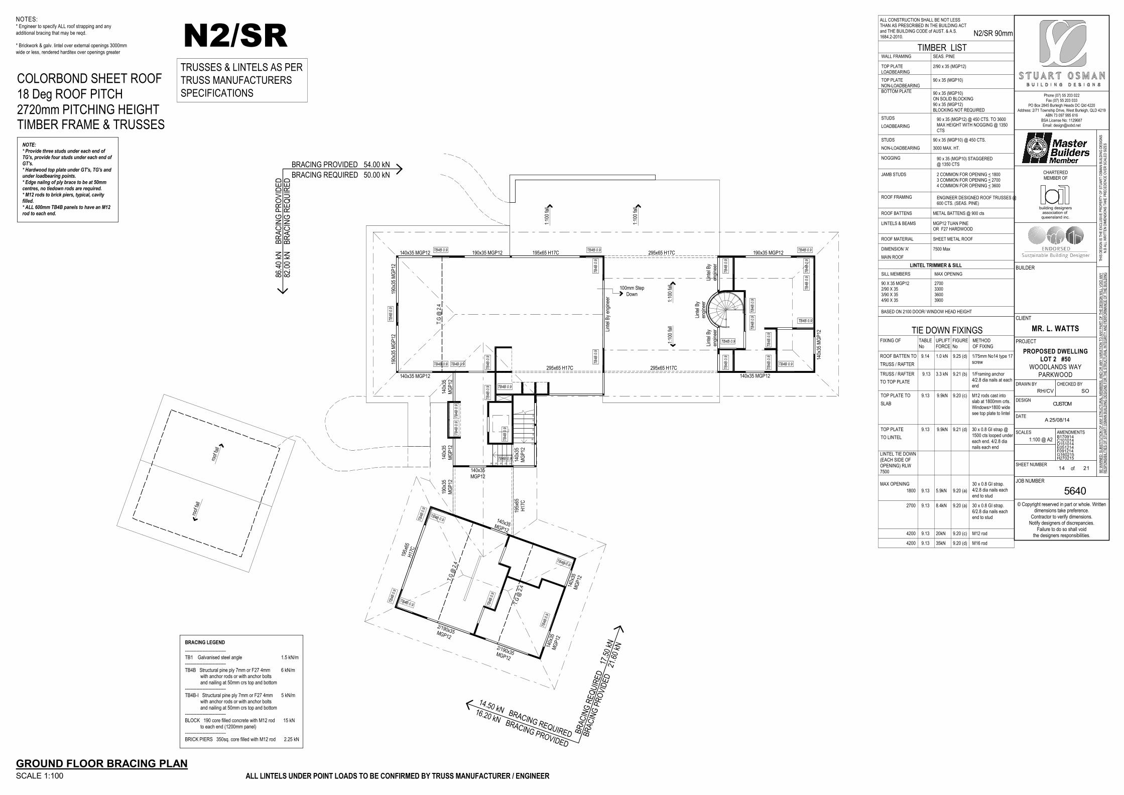
Phone (07) 55 203 022
Fax (07) 55 203 033PO Box 2845 Burleigh Heads DC Qld 4220
Address: 2/71 Township Drive, West Burleigh, QLD 4219ABN 73 097 995 616
BSA License No: 1129687Email: [email protected]
© Copyright reserved in part or whole. Writtendimensions take preference.
Contractor to verify dimensions.Notify designers of discrepancies.
Failure to do so shall voidthe designers responsibilities.
THIS
DE
SIG
N IS
TH
E E
XC
LUS
IVE
PR
OP
ER
TY
OF
ST
UA
RT
OS
MA
N B
UIL
DIN
G D
ES
IGN
SN
.B A
LL W
RIT
TE
N D
IME
NS
ION
S T
AK
E P
RE
CE
DE
NC
E O
VE
R S
CA
LED
SIZ
ES
BE
WA
RN
ED
: SU
BS
TIT
UT
ION
OF
AN
Y S
TR
UC
TU
RA
L M
EM
BE
RS
, AN
D O
R A
NY
VA
RIA
TIO
N T
O A
NY
PA
RT
OF
TH
E D
ES
IGN
WIL
L V
OID
AN
YR
ES
PO
NS
IBIL
ITIE
S O
F S
TU
AR
T O
SM
AN
BU
ILD
ING
DE
SIG
NS
FO
R T
HE
ST
RU
CT
UR
AL
INT
EG
RIT
Y A
ND
PE
RF
OR
MA
NC
E O
F T
HE
BU
ILD
ING
CLIENT
PROJECT
JOB NUMBER
BUILDER
DRAWN BY CHECKED BY
DESIGN
DATE
SCALES AMENDMENTS
SHEET NUMBERof
CHARTEREDMEMBER OF
MR. L. WATTS
PROPOSED DWELLING
LOT 2 #50WOODLANDS WAY
PARKWOOD
5640
RH/CV
A 25/08/14
B170914C101014D151014E051214F091214G160215H270215
SO
CUSTOM
1:100 @ A2
14 21
queensland inc.association of
building designers
MGP12 TUAN PINEOR F27 HARDWOOD
7500 Max
TOP PLATELOADBEARING
TOP PLATENON-LOADBEARINGBOTTOM PLATE
STUDS
LOADBEARING
STUDS
NON-LOADBEARING
NOGGING
JAMB STUDS
ROOF FRAMING
ROOF BATTENS
LINTELS & BEAMS
3000 MAX. HT.
2 COMMON FOR OPENING < 1800
4 COMMON FOR OPENING < 3600
METAL BATTENS @ 900 cts
ROOF MATERIAL SHEET METAL ROOF
WALL FRAMING SEAS. PINE
TIMBER LIST
3 COMMON FOR OPENING < 2700
DIMENSION 'A'
MAIN ROOF
2/90 x 35 (MGP12)
90 x 35 (MGP10)
90 x 35 (MGP10)ON SOLID BLOCKING90 x 35 (MGP12)BLOCKING NOT REQUIRED
90 x 35 (MGP12) @ 450 CTS. TO 3600MAX HEIGHT WITH NOGGING @ 1350CTS
90 x 35 (MGP10) @ 450 CTS.
90 x 35 (MGP10) STAGGERED@ 1350 CTS
N2/SR 90mm
ALL CONSTRUCTION SHALL BE NOT LESSTHAN AS PRESCRIBED IN THE BUILDING ACTand THE BUILDING CODE of AUST. & A.S.1684.2-2010.
ENGINEER DESIGNED ROOF TRUSSES @600 CTS. (SEAS. PINE)
SILL MEMBERS
LINTEL TRIMMER & SILL
MAX OPENING
BASED ON 2100 DOOR/ WINDOW HEAD HEIGHT
1/Framing anchor
4/2.8 dia nails at eachend
SLAB
TOP PLATE TO
9.21 (d)9.9kN
9.13
9.13
9.9kN 9.20 (c)
FIXING OF
No
TABLE UPLIFT
FORCE No
METHODFIGURE
OF FIXING
ROOF BATTEN TO
TRUSS / RAFTER
9.14 9.25 (d)
9.21 (b)9.13TRUSS / RAFTER
TO TOP PLATE
1/75mm No14 type 17
screw
TIE DOWN FIXINGS
LINTEL TIE DOWN
(EACH SIDE OFOPENING) RLW
7500
30 x 0.8 GI strap.
4/2.8 dia nails each
end to stud
30 x 0.8 GI strap.
6/2.8 dia nails eachend to stud
9.13
9.13
M12 rod
M16 rod
9.13
9.13
5.9kN
8.4kN
20kN
35kN
9.20 (a)
9.20 (a)
9.20 (c)
9.20 (d)
1.0 kN
3.3 kN
M12 rods cast intoslab at 1800mm crts.
Windows>1800 wide
see top plate to lintel
TOP PLATE
TO LINTEL
30 x 0.8 GI strap @
1500 cts looped under
each end. 4/2.8 dia
nails each end
90 X 35 MGP122/90 X 353/90 X 354/90 X 35
2700330036003900
MAX OPENING
1800
2700
4200
4200
TRUSSES & LINTELS AS PER
TRUSS MANUFACTURERS
SPECIFICATIONS
5
6
7
8
9
10
11
1213141516
TB4B 0.9
TB4B 0.9
TB4B 0.9TB4B 0.9TB4B 0.9
TB4B 0.9 TB4B 0.9
TB4B 0.9
TB4B 0.9
TB4B 0.9
TB
4B 0
.9
TB
4B 0
.9
TB
4B 0
.9
TB
4B 0
.9
TB
4B 0
.9T
B4B
0.9
TB
4B 0
.9
TB
4B 0
.9T
B4B
0.9
TB
4B 0
.9
TB
4B 0
.9
TB
4B 0
.9T
B4B
0.9
TB
4B 0
.9
TB
4B 0
.9T
B4B
0.9
TB4B
0.9
TB
4B 0
.9
TB
4B 0
.9
TB
4B 0
.9
TB4B 0.9
TB4B 0.9
TB4B 0.9
roof
fall
roof
fall
1:10
0 fa
ll
1:10
0 fa
ll
1:10
0 fa
ll1:
100
fall
T.G
@ 2
.4
T.G
@ 2
.4
T.G
@ 2
.4
Lint
el B
y en
gine
er
195x65 H17C190x35 MGP12
295x65 H17C
140x35 MGP12
140x35 MGP12
190x
35 M
GP
1219
0x35
MG
P12
140x35 MGP12
140x
35 M
GP
12
190x35 MGP12
140x35MGP12
140x
35M
GP
12
140x
35M
GP
12
195x
65H
17C
2/190x35MGP12
2/190x35MGP12
190x
35M
GP
12
195x
65H
17C
140x
35M
GP
12
140x35MGP12
140x
35M
GP
1214
0x35
MG
P12
Lint
el B
yen
gine
erLi
ntel
By
engi
neer
Lint
el B
yen
gine
er
295x65 H17C
295x65 H17C
100mm StepDown
GROUND FLOOR BRACING PLANSCALE 1:100
TIMBER FRAME & TRUSSES2720mm PITCHING HEIGHT18 Deg ROOF PITCHCOLORBOND SHEET ROOF
----------------------------
BRACING LEGEND
TB4B Structural pine ply 7mm or F27 4mm 6 kN/m with anchor rods or with anchor bolts and nailing at 50mm crs top and bottom
----------------------------TB1 Galvanised steel angle 1.5 kN/m
NOTE:* Provide three studs under each end ofTG's, provide four studs under each end ofGT's.* Hardwood top plate under GT's, TG's andunder loadbearing points.* Edge nailng of ply brace to be at 50mmcentres, no tiedown rods are required.* M12 rods to brick piers, typical, cavityfilled.* ALL 600mm TB4B panels to have an M12rod to each end.
N2/SR
BR
AC
ING
RE
QU
IRE
DB
RA
CIN
G P
RO
VID
ED
BRACING REQUIRED
82.0
0 kN
86.4
0 kN
50.00 kN
BRACING PROVIDED 54.00 kN
NOTES:* Engineer to specify ALL roof strapping and any
additional bracing that may be reqd.
* Brickwork & galv. lintel over external openings 3000mm
wide or less, rendered harditex over openings greater
ALL LINTELS UNDER POINT LOADS TO BE CONFIRMED BY TRUSS MANUFACTURER / ENGINEER
----------------------------
TB4B-I Structural pine ply 7mm or F27 4mm 5 kN/m with anchor rods or with anchor bolts and nailing at 50mm crs top and bottom----------------------------
BLOCK 190 core filled concrete with M12 rod 15 kN to each end (1200mm panel)----------------------------
BRICK PIERS 350sq. core filled with M12 rod 2.25 kN
BR
AC
ING
RE
QU
IRE
D
BR
AC
ING
PR
OV
IDE
D
BRACING REQUIRED
17.5
0 kN
21.6
0 kN
14.50 kN
BRACING PROVIDED
16.20 kN

Phone (07) 55 203 022
Fax (07) 55 203 033PO Box 2845 Burleigh Heads DC Qld 4220
Address: 2/71 Township Drive, West Burleigh, QLD 4219ABN 73 097 995 616
BSA License No: 1129687Email: [email protected]
© Copyright reserved in part or whole. Writtendimensions take preference.
Contractor to verify dimensions.Notify designers of discrepancies.
Failure to do so shall voidthe designers responsibilities.
THIS
DE
SIG
N IS
TH
E E
XC
LUS
IVE
PR
OP
ER
TY
OF
ST
UA
RT
OS
MA
N B
UIL
DIN
G D
ES
IGN
SN
.B A
LL W
RIT
TE
N D
IME
NS
ION
S T
AK
E P
RE
CE
DE
NC
E O
VE
R S
CA
LED
SIZ
ES
BE
WA
RN
ED
: SU
BS
TIT
UT
ION
OF
AN
Y S
TR
UC
TU
RA
L M
EM
BE
RS
, AN
D O
R A
NY
VA
RIA
TIO
N T
O A
NY
PA
RT
OF
TH
E D
ES
IGN
WIL
L V
OID
AN
YR
ES
PO
NS
IBIL
ITIE
S O
F S
TU
AR
T O
SM
AN
BU
ILD
ING
DE
SIG
NS
FO
R T
HE
ST
RU
CT
UR
AL
INT
EG
RIT
Y A
ND
PE
RF
OR
MA
NC
E O
F T
HE
BU
ILD
ING
CLIENT
PROJECT
JOB NUMBER
BUILDER
DRAWN BY CHECKED BY
DESIGN
DATE
SCALES AMENDMENTS
SHEET NUMBERof
CHARTEREDMEMBER OF
MR. L. WATTS
PROPOSED DWELLING
LOT 2 #50WOODLANDS WAY
PARKWOOD
5640
RH/CV
A 25/08/14
B170914C101014D151014E051214F091214G160215H270215
SO
CUSTOM
1:100 @ A2
15 21
queensland inc.association of
building designers
MGP12 TUAN PINEOR F27 HARDWOOD
7500 Max
TOP PLATELOADBEARING
TOP PLATENON-LOADBEARINGBOTTOM PLATE
STUDS
LOADBEARING
STUDS
NON-LOADBEARING
NOGGING
JAMB STUDS
ROOF FRAMING
ROOF BATTENS
LINTELS & BEAMS
3000 MAX. HT.
2 COMMON FOR OPENING < 1800
4 COMMON FOR OPENING < 3600
METAL BATTENS @ 900 cts
ROOF MATERIAL SHEET METAL ROOF
WALL FRAMING SEAS. PINE
TIMBER LIST
3 COMMON FOR OPENING < 2700
DIMENSION 'A'
MAIN ROOF
2/90 x 35 (MGP12)
90 x 35 (MGP10)
90 x 35 (MGP10)ON SOLID BLOCKING90 x 35 (MGP12)BLOCKING NOT REQUIRED
90 x 35 (MGP12) @ 450 CTS. TO 3600MAX HEIGHT WITH NOGGING @ 1350CTS
90 x 35 (MGP10) @ 450 CTS.
90 x 35 (MGP10) STAGGERED@ 1350 CTS
N2/SR 90mm
ALL CONSTRUCTION SHALL BE NOT LESSTHAN AS PRESCRIBED IN THE BUILDING ACTand THE BUILDING CODE of AUST. & A.S.1684.2-2010.
ENGINEER DESIGNED ROOF TRUSSES @600 CTS. (SEAS. PINE)
SILL MEMBERS
LINTEL TRIMMER & SILL
MAX OPENING
BASED ON 2100 DOOR/ WINDOW HEAD HEIGHT
1/Framing anchor
4/2.8 dia nails at eachend
SLAB
TOP PLATE TO
9.21 (d)9.9kN
9.13
9.13
9.9kN 9.20 (c)
FIXING OF
No
TABLE UPLIFT
FORCE No
METHODFIGURE
OF FIXING
ROOF BATTEN TO
TRUSS / RAFTER
9.14 9.25 (d)
9.21 (b)9.13TRUSS / RAFTER
TO TOP PLATE
1/75mm No14 type 17
screw
TIE DOWN FIXINGS
LINTEL TIE DOWN
(EACH SIDE OFOPENING) RLW
7500
30 x 0.8 GI strap.
4/2.8 dia nails each
end to stud
30 x 0.8 GI strap.
6/2.8 dia nails eachend to stud
9.13
9.13
M12 rod
M16 rod
9.13
9.13
5.9kN
8.4kN
20kN
35kN
9.20 (a)
9.20 (a)
9.20 (c)
9.20 (d)
1.0 kN
3.3 kN
M12 rods cast intoslab at 1800mm crts.
Windows>1800 wide
see top plate to lintel
TOP PLATE
TO LINTEL
30 x 0.8 GI strap @
1500 cts looped under
each end. 4/2.8 dia
nails each end
90 X 35 MGP122/90 X 353/90 X 354/90 X 35
2700330036003900
MAX OPENING
1800
2700
4200
4200
TRUSSES & LINTELS AS PER
TRUSS MANUFACTURERS
SPECIFICATIONS
TB4B 0.9
TB4B 0.9
TB
4B 0
.9
TB
4B 0
.9
TB
4B 0
.9
TB
4B 0
.9
roof
fall
roof
fall
roof fall
roof fall
roof
fall
roof fall
roof fall
roof
fall
roof fall roof fall
T.G
@ 2
.4
T.G
@ 2
.4
140x35MGP12
Lintel By Engineer
140x35MGP12
140x
35M
GP
12
140x
35M
GP
1214
0x35
MG
P12
FIRST FLOOR BRACING PLANSCALE 1:100
TIMBER FRAME & TRUSSES2440mm PITCHING HEIGHT18 Deg ROOF PITCHCOLORBOND SHEET ROOF
NOTE:* Provide three studs under each end ofTG's, provide four studs under each end ofGT's.* Hardwood top plate under GT's, TG's andunder loadbearing points.* Edge nailng of ply brace to be at 50mmcentres, no tiedown rods are required.* M12 rods to brick piers, typical, cavityfilled.* ALL 600mm TB4B panels to have an M12rod to each end.
N2/SRB
RA
CIN
G R
EQ
UIR
ED
BR
AC
ING
PR
OV
IDE
D
BRACING REQUIRED
20.0
0 kN
21.6
0 kN
8.50 kN
BRACING PROVIDED 10.80 kN
NOTES:* Engineer to specify ALL roof strapping and any
additional bracing that may be reqd.
* Brickwork & galv. lintel over external openings 3000mm
wide or less, rendered harditex over openings greater
ALL LINTELS UNDER POINT LOADS TO BE CONFIRMED BY TRUSS MANUFACTURER / ENGINEER
----------------------------
BRACING LEGEND
TB4B Structural pine ply 7mm or F27 4mm 6 kN/m with anchor rods or with anchor bolts and nailing at 50mm crs top and bottom
----------------------------TB1 Galvanised steel angle 1.5 kN/m
----------------------------
TB4B-I Structural pine ply 7mm or F27 4mm 5 kN/m with anchor rods or with anchor bolts and nailing at 50mm crs top and bottom----------------------------
BLOCK 190 core filled concrete with M12 rod 15 kN to each end (1200mm panel)----------------------------
BRICK PIERS 350sq. core filled with M12 rod 2.25 kN

Phone (07) 55 203 022
Fax (07) 55 203 033PO Box 2845 Burleigh Heads DC Qld 4220
Address: 2/71 Township Drive, West Burleigh, QLD 4219ABN 73 097 995 616
BSA License No: 1129687Email: [email protected]
© Copyright reserved in part or whole. Writtendimensions take preference.
Contractor to verify dimensions.Notify designers of discrepancies.
Failure to do so shall voidthe designers responsibilities.
THIS
DE
SIG
N IS
TH
E E
XC
LUS
IVE
PR
OP
ER
TY
OF
ST
UA
RT
OS
MA
N B
UIL
DIN
G D
ES
IGN
SN
.B A
LL W
RIT
TE
N D
IME
NS
ION
S T
AK
E P
RE
CE
DE
NC
E O
VE
R S
CA
LED
SIZ
ES
BE
WA
RN
ED
: SU
BS
TIT
UT
ION
OF
AN
Y S
TR
UC
TU
RA
L M
EM
BE
RS
, AN
D O
R A
NY
VA
RIA
TIO
N T
O A
NY
PA
RT
OF
TH
E D
ES
IGN
WIL
L V
OID
AN
YR
ES
PO
NS
IBIL
ITIE
S O
F S
TU
AR
T O
SM
AN
BU
ILD
ING
DE
SIG
NS
FO
R T
HE
ST
RU
CT
UR
AL
INT
EG
RIT
Y A
ND
PE
RF
OR
MA
NC
E O
F T
HE
BU
ILD
ING
CLIENT
PROJECT
JOB NUMBER
BUILDER
DRAWN BY CHECKED BY
DESIGN
DATE
SCALES AMENDMENTS
SHEET NUMBERof
CHARTEREDMEMBER OF
MR. L. WATTS
PROPOSED DWELLING
LOT 2 #50WOODLANDS WAY
PARKWOOD
5640
RH/CV
A 25/08/14
B170914C101014D151014E051214F091214G160215H270215
SO
CUSTOM
1:100 @ A2
16 21
queensland inc.association of
building designers
6,290 1,290
11,3
70
5,18
06,
090
100
7,580
3,000 4,580
11,3
70
3,59
01,
400
6,38
0
190
9,844 DIA
GONAL DIM
ENSION
6,19
050
5,95
0
140
50
5090
2,91
0
90
2,86
0
50
9050
6,190 50
3,140
2,860
9050
5090
2,910
9050
2,860
9050
6,19
050
902,
910
90
2,91
090
50
50140
5,860
9050 6,190
7,580
Slab & footing design toengineers detail
Column pad footing toengineers detail
Slab & footing design toengineers detail
tub
fw
PADRL - 51.400mFFLRL - 51.610m
(all levels t.b.c on site)
150mmstepdown
150mmstepdown
PADRL - 51.600mFFLRL - 51.800m
(all levels t.b.c on site)
BASEMENT SLAB PLANSCALE 1:100
NOTES:* Slab and Footings as per engineers designs* Provide Termite Protection as per AS 3660* ALL floor levels t.b.c on site* ALL floor joist to be specified by engineer
JOIST LAYOUT IS DIAGRAMMATIC ONLY - ENGINEER TO CONFIRMALL MEMBERS TO BE SPECIFIED BY ENGINEER
ALL BEAMS TO BE IN PLANE OF FLOOR JOISTS WHERE POSSIBLE

Phone (07) 55 203 022
Fax (07) 55 203 033PO Box 2845 Burleigh Heads DC Qld 4220
Address: 2/71 Township Drive, West Burleigh, QLD 4219ABN 73 097 995 616
BSA License No: 1129687Email: [email protected]
© Copyright reserved in part or whole. Writtendimensions take preference.
Contractor to verify dimensions.Notify designers of discrepancies.
Failure to do so shall voidthe designers responsibilities.
THIS
DE
SIG
N IS
TH
E E
XC
LUS
IVE
PR
OP
ER
TY
OF
ST
UA
RT
OS
MA
N B
UIL
DIN
G D
ES
IGN
SN
.B A
LL W
RIT
TE
N D
IME
NS
ION
S T
AK
E P
RE
CE
DE
NC
E O
VE
R S
CA
LED
SIZ
ES
BE
WA
RN
ED
: SU
BS
TIT
UT
ION
OF
AN
Y S
TR
UC
TU
RA
L M
EM
BE
RS
, AN
D O
R A
NY
VA
RIA
TIO
N T
O A
NY
PA
RT
OF
TH
E D
ES
IGN
WIL
L V
OID
AN
YR
ES
PO
NS
IBIL
ITIE
S O
F S
TU
AR
T O
SM
AN
BU
ILD
ING
DE
SIG
NS
FO
R T
HE
ST
RU
CT
UR
AL
INT
EG
RIT
Y A
ND
PE
RF
OR
MA
NC
E O
F T
HE
BU
ILD
ING
CLIENT
PROJECT
JOB NUMBER
BUILDER
DRAWN BY CHECKED BY
DESIGN
DATE
SCALES AMENDMENTS
SHEET NUMBERof
CHARTEREDMEMBER OF
MR. L. WATTS
PROPOSED DWELLING
LOT 2 #50WOODLANDS WAY
PARKWOOD
5640
RH/CV
A 25/08/14
B170914C101014D151014E051214F091214G160215H270215
SO
CUSTOM
1:100 @ A2
17 21
queensland inc.association of
building designers
2,220
903,
700
2,19
0
8,04
5 DIA
GO
NAL DIM
ENSION
7,590 290 7,380 3,400 5,060
1,590 6,000 11,070 5,060
1,590 10,980 6,000 5,150
600 90
2,38
51,
879
1,91
6
290
15,4
60
3,40
01,
590
6,18
04,
000
290
3,40
011
,770
290
5,35
01,
186
3,63
53,
790
7,38
04,
000
290
15,4
60
1,10
02,
300
9,36
02,
700
2,74
55,
350
2,07
51,
510
1,98
01,
500
6,18
02,
804
1,48
6
2,50
090
1,18
02,
520
7,38
04,
000
290
1,090 1,110 90
2,200
2,190 1,200 900300
8,170
5,68
0
2,50
0
1,50
01,
680
90
1,200
6,880
300 2,090 1,090 1,110 90 3,600
3,180 1,200 3,510 6,180 5,060
390
90 90
1,59
0
901,
110
2,59
0
901,
000
1,000 1,000
1,036
23,720
90
3,000
1,98
01,
500
R 1,036
Slab & footing designto engineers detail
sink
show
er
wc
wc
basin
basin
fw
fw
shower
wc
basin
fw
bath
fw fw
basin
100mmstepdown
FFLRL - 54.600m(all levels t.b.c on site)
100mmstepdown
100mmstepdown
STA
IR
VO
ID
PADRL - 54.300mFFLRL - 54.600m
(all levels t.b.c on site)
PADRL - 54.300mFFLRL - 54.600m
(all levels t.b.c on site)
Timberdecking
Timberdecking
Bearers & Joists
Timberdecking
Concretetiles
Concretetiles
GROUND FLOOR SLAB PLANSCALE 1:100
NOTES:* Slab and Footings as per engineers designs* Provide Termite Protection as per AS 3660* ALL floor levels t.b.c on site* ALL floor joist to be specified by engineer

Phone (07) 55 203 022
Fax (07) 55 203 033PO Box 2845 Burleigh Heads DC Qld 4220
Address: 2/71 Township Drive, West Burleigh, QLD 4219ABN 73 097 995 616
BSA License No: 1129687Email: [email protected]
© Copyright reserved in part or whole. Writtendimensions take preference.
Contractor to verify dimensions.Notify designers of discrepancies.
Failure to do so shall voidthe designers responsibilities.
THIS
DE
SIG
N IS
TH
E E
XC
LUS
IVE
PR
OP
ER
TY
OF
ST
UA
RT
OS
MA
N B
UIL
DIN
G D
ES
IGN
SN
.B A
LL W
RIT
TE
N D
IME
NS
ION
S T
AK
E P
RE
CE
DE
NC
E O
VE
R S
CA
LED
SIZ
ES
BE
WA
RN
ED
: SU
BS
TIT
UT
ION
OF
AN
Y S
TR
UC
TU
RA
L M
EM
BE
RS
, AN
D O
R A
NY
VA
RIA
TIO
N T
O A
NY
PA
RT
OF
TH
E D
ES
IGN
WIL
L V
OID
AN
YR
ES
PO
NS
IBIL
ITIE
S O
F S
TU
AR
T O
SM
AN
BU
ILD
ING
DE
SIG
NS
FO
R T
HE
ST
RU
CT
UR
AL
INT
EG
RIT
Y A
ND
PE
RF
OR
MA
NC
E O
F T
HE
BU
ILD
ING
CLIENT
PROJECT
JOB NUMBER
BUILDER
DRAWN BY CHECKED BY
DESIGN
DATE
SCALES AMENDMENTS
SHEET NUMBERof
CHARTEREDMEMBER OF
MR. L. WATTS
PROPOSED DWELLING
LOT 2 #50WOODLANDS WAY
PARKWOOD
5640
RH/CV
A 25/08/14
B170914C101014D151014E051214F091214G160215H270215
SO
CUSTOM
1:100 @ A2
18 21
queensland inc.association of
building designers
1,49
0
1,490
1,490
1,49
0 2,10
7
200
Cantilevered Steel Beamas per engineers design
Cantilevered Steel Beamas per engineers design
Stair Trimmeras per engineers design
Stair Trimmeras per engineers design
Cantilevered Steel Beamas per engineers design
Floor Joists @ 450 Ctrsas per engineers designFloor Joists @ 450 Ctrsas per engineers designFloor Joists @ 450 Ctrsas per engineers designFloor Joists @ 450 Ctrsas per engineers design
Stair VOID
Cantilevered Floor Joists
Floor Joists to be Packed upto Internal Floor Joists Level Connection Detail
as per Engineers Details
Connection Detailas per Engineers Details
CantileveredJoists
CantileveredJoists
Can
tilev
ered
Jois
ts
Can
tilev
ered
Jois
ts
Floor Joists @ 450 Ctrs asper engineers design
Beam in roof space as perengineers design
Beam in roof space as perengineers design
Trimmer beam around stairs in floorspace as per engineers design
Floor Joists @ 450 Ctrs asper engineers designFloor Joists @ 450 Ctrs asper engineers designFloor Joists @ 450 Ctrs asper engineers design
Floor Joists to be CantileveredTo Stair Trimmer
VOID
FLOOR JOIST PLANSSCALE 1:100
GROUND FLOOR JOIST PLAN
FIRST FLOOR JOIST PLAN
SUGGESTED LAYOUT ONLY, TBC BY ENGINEER

Phone (07) 55 203 022
Fax (07) 55 203 033PO Box 2845 Burleigh Heads DC Qld 4220
Address: 2/71 Township Drive, West Burleigh, QLD 4219ABN 73 097 995 616
BSA License No: 1129687Email: [email protected]
© Copyright reserved in part or whole. Writtendimensions take preference.
Contractor to verify dimensions.Notify designers of discrepancies.
Failure to do so shall voidthe designers responsibilities.
THIS
DE
SIG
N IS
TH
E E
XC
LUS
IVE
PR
OP
ER
TY
OF
ST
UA
RT
OS
MA
N B
UIL
DIN
G D
ES
IGN
SN
.B A
LL W
RIT
TE
N D
IME
NS
ION
S T
AK
E P
RE
CE
DE
NC
E O
VE
R S
CA
LED
SIZ
ES
BE
WA
RN
ED
: SU
BS
TIT
UT
ION
OF
AN
Y S
TR
UC
TU
RA
L M
EM
BE
RS
, AN
D O
R A
NY
VA
RIA
TIO
N T
O A
NY
PA
RT
OF
TH
E D
ES
IGN
WIL
L V
OID
AN
YR
ES
PO
NS
IBIL
ITIE
S O
F S
TU
AR
T O
SM
AN
BU
ILD
ING
DE
SIG
NS
FO
R T
HE
ST
RU
CT
UR
AL
INT
EG
RIT
Y A
ND
PE
RF
OR
MA
NC
E O
F T
HE
BU
ILD
ING
CLIENT
PROJECT
JOB NUMBER
BUILDER
DRAWN BY CHECKED BY
DESIGN
DATE
SCALES AMENDMENTS
SHEET NUMBERof
CHARTEREDMEMBER OF
MR. L. WATTS
PROPOSED DWELLING
LOT 2 #50WOODLANDS WAY
PARKWOOD
5640
RH/CV
A 25/08/14
B170914C101014D151014E051214F091214G160215H270215
SO
CUSTOM
1:100 @ A2
19 21
queensland inc.association of
building designers
2,44
02,
720
940940
1,2401,240
900
700
51.760
54.600
1,240
100
18 degree Stramit colorbond custom orb roof sheeting
Stramit colorbond fascias,gutters & downpipes
Plasterboard lining towalls & ceiling Approx. NGL
Slab & footing design as perengineers details
Agg Drain
190mm blockworkwalls, to engineersspecs
18 degree Stramit colorbond custom orb roof sheeting
Stramit colorbond fascias,gutters & downpipes
Powdercoated aluminiumwindows & SGDs
Hardies 'LINEA'weatherboard cladding
1000mm high handrail
Rendered FCsheeting orsimilar
Rendered FC sheeting or similar
SECTION 1:100
8-10
CL
CL
FL
CL
FL
CL
FL
B
incl. 40fascia
ENTRY
incl. 40fascia
incl. 40fascia
incl. 40fascia
fgfg
incl. 40fascia
Tru
ssU
psta
nd
Floor Joists at450 ctrs
BINDERS @ 3000 CTRS
Stair info:16x risers @ 177.5mm,Treads @ 250mm going
FL
2,44
02,
720
100
2,72
010
0
940 940
2,59
051.760
54.600 54.500 54.600
51.610
1,240
450
Slab & footings toengineers design
18 degree Stramit colorbond custom orb roof sheeting
Stramit colorbond fascias,gutters & downpipes
Plasterboard lining towalls & ceiling
Approx. NGL
190mm blockworkwalls, to engineersspecs
18 degree Stramit colorbond custom orb roof sheeting
Stramit colorbond fascias,gutters & downpipes
Stair info:16x risers @ 177.5mm,Treads @ 250mm going
Raked Eave Rendered FC sheetingor similar
HomeGuard termite protectionsystem to underside of slab,perimeter & penetrations, inaccordance with AS 3660.1
CL
CL
FL
CL
FL
incl. 40fascia
GARAGE
MEALSSTAIRVOID ENS
COVEREDWALKWAY
100mmstepdown
W.I.R
fg fg
inc 40fascia
inc 40fascia
SECTION 1:100
8-10C
Tru
ssU
psta
nd
Tru
ssU
psta
nd
Floor Joists at 450 ctrs as per Engineers Details
BINDERS @ 3000 CTRS BINDERS @ 3000 CTRS
Agg DrainAgg Drain
FL
2,44
02,
720
100
2,72
010
0
940 940
2,59
0
51.760
54.600
51.610
54.500
1,240
1,490
Slab & footings toengineers design
18 degree Stramit colorbond custom orb roof sheeting
Stramit colorbond fascias,gutters & downpipes
Plasterboard lining towalls & ceiling
Approx. NGL
190mm blockwork walls, toengineers specs
18 degree Stramit colorbond custom orb roof sheeting
Stramit colorbond fascias,gutters & downpipes
Raked Ceiling
Rendered FCsheeting orsimilar
Ground to be kept clearof Cantilevered Decks
HomeGuard termite protectionsystem to underside of slab,perimeter & penetrations, inaccordance with AS 3660.1
CL
CL
FL
CL
FL
100mmstepdown
incl. 40fascia
GARAGE LAUNDRY
LIVING ENTRY BED 1COVEREDWALKWAY
Deck Joists @ 450 Ctrs
fg fginc 40fascia
inc 40fascia
SECTION 1:100
8-10D
Tru
ssU
psta
nd
Tru
ssU
psta
nd
Cantilevered Floor Joist asper Engineers Details
Floor Joist as per Engineers Details
Agg Drain
FL
100mmstepdown
BINDERS @ 3000 CTRS BINDERS @ 3000 CTRS
2,72
02,
440
1,2401,240
54.600
57.720
54.500
940940
100
Slab & footings toengineers design
18 degree Stramit colorbond custom orb roof sheeting
Stramit colorbond fascias,gutters & downpipes
Plasterboard lining towalls & ceiling
Floor joists @450 Ctrs
18 degree Stramit colorbond custom orb roof sheeting
Approx. NGL
Raked Eaves
Rendered FC sheeting or similar
HomeGuard termite protectionsystem to underside of slab,perimeter & penetrations, inaccordance with AS 3660.1SECTION 1:100
8-10
CL
FL
CL
FL
CL
FL
CL
FL
A
incl. 40fascia
incl. 40fascia
incl. 40fascia
incl. 40fascia
BREEZEWAYPATIO
BED 3
Tru
ssU
psta
nd
BINDERS @ 3000 CTRS

Phone (07) 55 203 022
Fax (07) 55 203 033PO Box 2845 Burleigh Heads DC Qld 4220
Address: 2/71 Township Drive, West Burleigh, QLD 4219ABN 73 097 995 616
BSA License No: 1129687Email: [email protected]
© Copyright reserved in part or whole. Writtendimensions take preference.
Contractor to verify dimensions.Notify designers of discrepancies.
Failure to do so shall voidthe designers responsibilities.
THIS
DE
SIG
N IS
TH
E E
XC
LUS
IVE
PR
OP
ER
TY
OF
ST
UA
RT
OS
MA
N B
UIL
DIN
G D
ES
IGN
SN
.B A
LL W
RIT
TE
N D
IME
NS
ION
S T
AK
E P
RE
CE
DE
NC
E O
VE
R S
CA
LED
SIZ
ES
BE
WA
RN
ED
: SU
BS
TIT
UT
ION
OF
AN
Y S
TR
UC
TU
RA
L M
EM
BE
RS
, AN
D O
R A
NY
VA
RIA
TIO
N T
O A
NY
PA
RT
OF
TH
E D
ES
IGN
WIL
L V
OID
AN
YR
ES
PO
NS
IBIL
ITIE
S O
F S
TU
AR
T O
SM
AN
BU
ILD
ING
DE
SIG
NS
FO
R T
HE
ST
RU
CT
UR
AL
INT
EG
RIT
Y A
ND
PE
RF
OR
MA
NC
E O
F T
HE
BU
ILD
ING
CLIENT
PROJECT
JOB NUMBER
BUILDER
DRAWN BY CHECKED BY
DESIGN
DATE
SCALES AMENDMENTS
SHEET NUMBERof
CHARTEREDMEMBER OF
MR. L. WATTS
PROPOSED DWELLING
LOT 2 #50WOODLANDS WAY
PARKWOOD
5640
RH/CV
A 25/08/14
B170914C101014D151014E051214F091214G160215H270215
SO
CUSTOM
1:100 @ A2
20 21
queensland inc.association of
building designers
2,44
02,
720
100
2,72
010
0
1,240
940940
51.760
54.600
51.610
54.50054.500
1,240
1,490
Slab & footings toengineers design
18 degree Stramit colorbond custom orb roof sheeting
Stramit colorbond fascias,gutters & downpipes
Plasterboard lining towalls & ceiling
Approx. NGL190mm blockwork walls, to
engineers specs
18 degree Stramit colorbond custom orb roof sheeting
Stramit colorbond fascias,gutters & downpipes
Powdercoated aluminiumwindows & SGDs
Hardies 'LINEA'weatherboard cladding
1000mm highhandrail
Raked Ceiling
Rendered FCsheeting or similar
Rendered FCsheeting or similar
Provide sub-floor ventilation,as per BCA 3.4.1.1
HomeGuard termite protectionsystem to underside of slab,perimeter & penetrations, inaccordance with AS 3660.1
CL
CL
FL
CL
FL
100mmstepdown
inc 40fascia
PORCH LAUNDRY
KITCHENENTRYBALCONYBREEZEWAY
150mmstepdown
incl. 40fascia
incl. 40fascia
incl. 40fascia
SECTION 1:100
8-10E
Tru
ssU
psta
nd
Tru
ssU
psta
nd
Cantileverjoists
Floor Joists @ 450 ctrs as per Engineers Details
Deck Joists @ 450 ctrsas per Engineers Details
Agg Drain
FL
BINDERS @ 3000 CTRS
2,59
02,
720
2,44
0
2,72
02,
440
51.610
54.600 54.500
57.7201,240
1,240
940 940
100
100
1,490
18 degree Stramit colorbond custom orb roof sheetingStramit colorbond
fascias, gutters &downpipes
Plasterboard liningto walls & ceiling
190mm blockwork walls, toengineers specs
Floor Joists @ 450 Ctrs
Plasterboard lining to walls& ceiling
18 degree Stramit colorbond custom orb roof sheeting
Approx. NGL
1000mm AFFLhigh handrail
Raked Eaves
Rendered FCsheeting or similar
Rendered FC sheeting or similar
Joists to be Packed Up
CL
CL
FL
CL
FL
CL
FL
CL
FL
incl. 40fascia
incl. 40fascia
incl. 40fascia
incl. 40fascia
100mmstepdown
GARAGE
LIVING MEALSBALCONY BREEZEWAY BED 2 BATH
BED 3 ENS
fg
fg fg
SECTION 1:100
8-10F
Tru
ssU
psta
nd
Tru
ssU
psta
nd
Cantileverjoists
Floor Joists at 450 ctrs as per Engineers DetailsCantilevered Floor Joists at 450 ctrsas per Engineers Details
Slab & footings toengineers design
Agg Drain
Spiral Stair info:15x no risers @ 208mmTotal rise - 3120mm945mm Radius
Provide sub-floor ventilation,as per BCA 3.4.1.1
Junction as per Engineer Details
HomeGuard termite protectionsystem to underside of slab,perimeter & penetrations, inaccordance with AS 3660.1
FL
BINDERS @ 3000 CTRS
BINDERS @ 3000 CTRS
100mmstepdown
100mmstepdown
2,59
0
2,72
010
0
2,72
010
0
54.600
51.800
1,240
1,240
600
1,99
0
Slab & footings toengineers design
Plasterboard lining to walls& ceiling
18 degree Stramit colorbond custom orb roof sheeting
Approx. NGL90x90 SHSsteel posts
Stramit colorbond fascias,gutters & downpipes
18 degree Stramit colorbond custom orb roof sheeting
Stramit colorbond fascias,gutters & downpipes
Powdercoated aluminiumwindows & SGDs
Hardies 'LINEA'weatherboard cladding
1000mm high handrail
18 degree Stramit colorbond custom orb roof sheeting
Raked Ceiling
RakedEaves
Rendered FCsheeting or similar
Rendered FC sheeting or similar
HomeGuard termite protectionsystem to underside of slab,perimeter & penetrations, inaccordance with AS 3660.1
Spoon drain
CL
FL
CL
FLCL
FL
incl. 40fascia
incl. 40fascia
BED 1 ENS
CARPORT
fg fg fg
fg fg
SECTION 1:100
8-10G
Tru
ssU
psta
nd
Tru
ssU
psta
nd
BINDERS @ 3000 CTRS
2,59
0
650 650
51.800
600
1,99
0
Slab & footings toengineers design
18 degree Stramit colorbond custom orb roof sheeting
Approx. NGL90x90 SHSsteel posts
Stramit colorbond fascias,gutters & downpipes
Rakedceiling
Rafters as per engineersdetails
Spoon drain
CL
FL
CL
FL
CARPORT
inc 40 fascia inc 40 fascia
SECTION 1:100
8-10H
2,72
010
0
54.600
1,240 1,240
Slab & footings toengineers design
18 degree Stramit colorbond custom orb roof sheeting
Approx. NGL
Stramit colorbond fascias,gutters & downpipes
Plasterboard lining towalls & ceiling
Raked Eaves
Rendered FCsheeting or similar
HomeGuard termite protectionsystem to underside of slab,perimeter & penetrations, inaccordance with AS 3660.1
CL
FL
CL
FL
W.I.R ENS
inc. 40fascia
inc. 40fascia
Binders @ 3000 Ctrs
SECTION 1:100
8-10I
Tru
ssU
psta
nd
2,72
0
900
1,52
030
0
900
700
820
300
FL
CL
FL
CL
fg Cooktop
WOSpaceOnly
MWSpaceOnly
PANTRY
2,72
0
2,42
030
0
1,82
060
030
0
FL
CL
FL
CL
PANTRY
REF.SpaceOnly
KITCHEN ELEVATION 2 1:50
2,72
0
900
1,82
0
FL
CL
FL
CL
DW SpaceOnly
Sink
KITCHEN ELEVATION 3 1:50

Phone (07) 55 203 022
Fax (07) 55 203 033PO Box 2845 Burleigh Heads DC Qld 4220
Address: 2/71 Township Drive, West Burleigh, QLD 4219ABN 73 097 995 616
BSA License No: 1129687Email: [email protected]
© Copyright reserved in part or whole. Writtendimensions take preference.
Contractor to verify dimensions.Notify designers of discrepancies.
Failure to do so shall voidthe designers responsibilities.
THIS
DE
SIG
N IS
TH
E E
XC
LUS
IVE
PR
OP
ER
TY
OF
ST
UA
RT
OS
MA
N B
UIL
DIN
G D
ES
IGN
SN
.B A
LL W
RIT
TE
N D
IME
NS
ION
S T
AK
E P
RE
CE
DE
NC
E O
VE
R S
CA
LED
SIZ
ES
BE
WA
RN
ED
: SU
BS
TIT
UT
ION
OF
AN
Y S
TR
UC
TU
RA
L M
EM
BE
RS
, AN
D O
R A
NY
VA
RIA
TIO
N T
O A
NY
PA
RT
OF
TH
E D
ES
IGN
WIL
L V
OID
AN
YR
ES
PO
NS
IBIL
ITIE
S O
F S
TU
AR
T O
SM
AN
BU
ILD
ING
DE
SIG
NS
FO
R T
HE
ST
RU
CT
UR
AL
INT
EG
RIT
Y A
ND
PE
RF
OR
MA
NC
E O
F T
HE
BU
ILD
ING
CLIENT
PROJECT
JOB NUMBER
BUILDER
DRAWN BY CHECKED BY
DESIGN
DATE
SCALES AMENDMENTS
SHEET NUMBERof
CHARTEREDMEMBER OF
MR. L. WATTS
PROPOSED DWELLING
LOT 2 #50WOODLANDS WAY
PARKWOOD
5640
RH/CV
A 25/08/14
B170914C101014D151014E051214F091214G160215H270215
SO
CUSTOM
1:100 @ A2
21 21
queensland inc.association of
building designers
NOTE:
2/30x0.8mm GI strap fixed to top plates & studs at each end with 4/2.8mm
diam nails.
External wall
Internal bracing wall
35mm gap to truss
Blocking pieces to both sidesof truss bottom chord fixed totop plate with 4/3.33 diam. nails
Bottom chord of truss
Bracing wall
1800 min. 2700 max.
50
150
300
30x2.8mm diam flathead nailsnail spacing as shown
2/50x2.8mm diam nails at each endand each stud
1:20
7025
0320
20
Timber architrave
timber lintel beam, as per
Min 10mm gap
Timber reveal
4.5mm FC soffit sheet
TYPICAL FIXING TO TOP OF BRACING WALL 1:20
TYPICAL METAL ANGLE BRACING (TB1)1.5kN/m 1:50
4mm F27 PLYWOOD BRACING (TB4B)6.0 kN/m (rods not required) 1:50
finish as selected
DETAIL 1 1:10
size as per bracing plan
150mm GI strapunder top ribbonplate.
Gap to truss
end.diameter nails each3/75 x 3.33 mm
TRUSSES PARALLEL TO BRACING WALL 1:20
bridging piece90x35mm MPG12 timber
bracing wall
NOTE:
30 degs max
30x0.8mm gal. strap3/30x2.8mm dia nailsto end of stud
Metal angle of Min.nominal section18x16x1.2mm
Max depth of notchnot to exceed 20mm
Note: if two or more panelare butted together thevertical join nailing is tobe @50mm centres.
Single sheet vertical nailingto be @150mm centres.
Tie down to floor(nomial fixing only)
CANTELEVERED TRUSSES TO ACHIEVE600mm O'HANG WITH 25 deg ROOF PITCHWHERE 2440mm IS USED
or a
s no
min
ated
or a
s no
min
ated
waffle pod slab as per engineers design
with exposed edge for visual inspection
Termi-mesh or similar to all slab penetrations& perimeter
sarking to roof where applicable
openings and corners, from top plate to slab.12mm Rods at 1800mm cts, each side of
or as nominated on plans
or as nominated on plans
as selected
as selected
10mm plasterboard ceiling, paint finish
90mm cornice, paint finish as selected
timber architrave, as selected
aluminium framed window as selected
10mm plasterboard wall lining, paint finish
-
D1
GI partition bracket
manufacturers printed specificationsRoof trusses @ 600mm centres as per truss
FL
CL
21° roof pitch
320
2120
2440
moisture barrier
50mm sand bed
dia' nails each end over trusses to top plate
or 30 x 0.8mm GI strap with 3/2.8mm
one framing anchor to be fixed to each end
Sheet metal roof with metal battens @900mm cts
600
metal fascia & gutter
TRUSSES PERP.TO BRACING WALL
T.B.C by engineer
TYPICAL TIMBER FRAME SECTION 1:20
WITNESS DATE
amendmentsdesign drawn by
date
scales
job number
of
Phone (07) 55 203 022Fax (07) 55 203 033PO Box 2845 Burleigh HeadsDC Qld 4220
ABN 73 097 995 616QLD 4219
BSA License No: 1129687Email: [email protected]
PLEASE READ CAREFULLY
IN THE INITAL AGREEMENT AND I UNDERSTAND CHANGES
THIS PLAN CERTIFIED CORRECT IS THE ONE REFERRED TO
HEREAFTER MAY NOT BE POSSIBLE. THESE PLANS
SUPERSEDE ALL OTHER PREVIOUS PLANS OR SKETCHES.
OWNER/S
Contractor to verify dimensions. Notify designers ofdiscrepancies. Failure to do
so shall void the designers responsibilities.
dimensions take preference.© Copyright reserved in part or whole. Written
THIS DESIGN IS THE EXCLUSIVE PROPERTY OF STUART OSMAN BUILDING DESIGNS
N.B ALL WRITTEN DIMENSIONS TAKE PRECEDENCE OVER SCALED SIZES RESPONSIBILITIES OF STUART OSMAN BUILDING DESIGNS FOR THE STRUCTURAL INTEGRITY AND PERFORMANCE OF THE BUILDINGBE WARNED: SUBSTITUTION OF ANY STRUCTURAL MEMBERS, AND OR ANY VARIATION TO ANY PART OF THE DESIGN WILL VOID ANY
Address: 2/71 TownshipDrive, West Burleigh,
sheet #
checked by
of trusses and top plates with 6/2.8 dia' nails
windows wider than 1800mm, tohave top plate strapped to lintel@ 1800mm max centres with 30x 0.8 GI strap looped under eachend . 4.2.8 dia nails each end
Provide 1 per 900 sheet of bracing ply 2/30x0.8mm looped GI strapfixed over bridging piece & to underside of top plate with 4/2.8mmdiam nails at each end of straps & to bridging piece.
Suitable for 4200 max opening
30x0.8mm gal. strap3/30x2.8mm dia nailsto end of stud
13 kN capacity connection at each end &intermediately at max 1200 cts Suitable to anchor 1m of bracing ply
Engage minimum 2 trusses per 1m of bracing ply
4.5mm FC soffit lining, paint finish as selected.Flat or raking soffit. refer sections/ builders spec.
N2/SR/timber frame
N2/SR/timber frame
WALL CLADDING ASNOMINATED ON PLANS
RH/CVCUSTOM
5640
MR. L. WATTSLOT 2 #50 WOODLANDS WAY
PARKWOOD A 25/08/14
21211:100 @ A3
####