Embed Size (px)
Citation preview
S
E
V
E
N
T
H
A
V
E
N
U
E
S
I
X
T
H
A
V
E
N
U
E
B
a
a
k
e
n
s
R
i
v
e
r
A
L
C
O
C
K
R
O
A
D
R
I
V
E
R
R
O
A
D
C
L
I
F
F
L
A
N
E
3
6
6
8
3
6
4
3
6
3
3
1
8
8
3
4
4
4
5
4
4
4
4
4
3
4
4
2
4
5
2
4
4
0
4
3
9
4
3
8
4
3
7
4
3
1
4
3
3
4
3
2
4
2
7
4
2
6
4
2
2
3
6
5
4
9
8
1
3
6
0
3
0
2
8
4
5
3
5
6
2
0
5
1
2
0
5
3
4
4
4
3
0
4
2
9
4
2
8
4
2
1
4
2
0
5
8
8
4
1
9
4
2
3
4
2
4
4
1
5
4
1
6
4
1
8
4
1
7
3
3
3
3
4
9
3
4
8
3
3
8
3
4
7
3
4
6
3
4
5
2
8
4
6
3
0
3
3
2
7
3
9
0
3
7
3
9
1
7
5
1
3
7
9
2
0
1
9
3
5
4
3
4
1
0
4
3
9
5
0
2
9
5
0
3
0
r
e
m
2
8
2
9
2
5
2
2
2
6
3
0
1
7
1
5
9
2
3
2
7
3
6
3
8
4
2
4
6
2
9
3
1
3
5
3
9
8
1
0
1
2
1
6
2
0
2
4
2
6
1
7
2
1
5
8
5
6
6
3
3
7
5
4
5
0
4
5
2
5
4
7
4
9
5
1
5
5
1
1
6
6
9
R
I
V
E
R
R
O
A
D
1 855
20 361
ss1/110mm VP
1:10
DISTANCE
DEPTH
GROUND LEVEL
INVERT LEVEL
GRADIENT
DISTANCE
DEPTH
GROUND LEVEL
INVERT LEVEL
GRADIENT
3 738
1 779
22 253
110m
m P
VC
SE
WE
R P
IPE
@
MA
X 1
:10 &
MIN
1:6
0 A
S P
ER
NB
R
1 714
20 173
1 420
19 781
Ie1 Ie2 Ie3
MU
NIC
IP
AL C
ON
NE
CT
IO
N
1:10 1:10 1:10
465 971 23 436
GF @ 23 725
LGF @ 20 000
5 116
18 50620 474
18 45918 361 2 795
2 321
GF @ 23 725
LGF @ 20 000
ss2
G
re
re
re
re
re
re
re
MUNICIPAL
CONNECTION @ 2321
N
G
L
N
G
L
wc
whbsink
DW /
WM
wc
whb
depth as per diagram
Ie4
wc
whb
110mm vp
ss3
110mm vp
ss1
shower
110m
m P
VC
SE
WE
R P
IPE
@
MA
X 1
:10 &
MIN
1:6
0 A
S P
ER
NB
R
110m
m P
VC
SE
WE
R P
IPE
@
MA
X 1
:10 &
MIN
1:6
0 A
S P
ER
NB
R
110m
m P
VC
SE
WE
R P
IPE
@
MA
X 1
:10 &
MIN
1:6
0 A
S P
ER
NB
R
110m
m P
VC
SE
WE
R P
IPE
@
MA
X 1
:10 &
MIN
1:6
0 A
S P
ER
NB
R
110m
m P
VC
SE
WE
R P
IPE
@
MA
X 1
:10 &
MIN
1:6
0 A
S P
ER
NB
R
All dimensions are given in millimeters, unless otherwise specified.
All dimensions to be checked on site before construction
commences. Contractors to adhere to all local authority's
regulations and requirements. Contractors to be a suitably qualifiedand registered participant in the construction industry as required byConstruction Regulation 2014. Drawings to be read in conjunctionwith the clients OHS (Occupational Health and Safety) file.All work to be done in accordance with the National Building
Regulations SANS 10400. Before this drawing is priced it is the
contractor's responsibility to ensure he is familiar with the site. All
trade names quoted may only be substituted by similar, subject to
architect's approval. All materials to be installed in strict
accordance with manufacturer's specifications. All conduit work to
be SABS approved quality. All light fittings is to be fitted to comply
with the relevant code of practice as specified in SANS 10400:
Part O. All new work to be made good with existing. This drawing
is not to be scaled. All dimensions not to be scaled from drawings
and heights to be checked on site. Any discrepancies shall be
reported to the designer immediately. Top of foundations to be a
minimum of 150mm below finished ground level. Minimum 100mm
thick concrete surface bed as per Engineers drawings to be on
"gunplas" ubs green damp proof membrane on 50mm sand
blinding layer on well compacted fill. SABS Approved "gundle"
375 mic. dpc under all walls, window cills and at changes in floor
level. These architectural drawings to be read in conjunction with
engineers and consultants drawings where applicable. All building
work to be carried out in accordance with the national building
regulations. The contractor is responsible for all site visits by local
inspectors and pay all fees in connection therewith. All drainage
work to be carried out in accordance with the national building
regulations. All roof measurements to be taken on site by roof
specialist prior to roof construction. All tile layouts to be confirmed
with architect prior to commencement of tiling. Any discrepancies
must be clarified by the architect prior to commencement of work.
Levels shown are relative to a benchmark at 100.00 msl of new
floor level. Msl is not the actual level but a benchmark to base
other heights of the building shown on the drawings. Contractor to
keep a full set of latest issued drawings on site. Contractor is
responsible for the correct setting out of the building on site with
reference to the building line and boundaries. Contractor to take
responsibility for all health and safety measures on site.
GENERAL NOTES:
REVISIONS:
COPYRIGHT:
This drawing is subject to copyright, and may not be reproduced in
whole or part in any matter whatsoever without written permission
from DMV Architecture.
ERF NO:
EXISTING AREA:
NEW AREA:
TOTAL AREA:
NEW GARAGES
NEW BATHROOMS:
ERF AREA
EX. COVERAGE
NEW COVERAGE
AGE OF BUILDING
Unit 6
1 Bridge Street
Reg no. PrArch 21014
ARCHITECT SIGNATURE
...................................
South End
6001
TEL: 041 581 1590
CELL: 083 295 3601
FAX: 086 547 5423
email: [email protected]
MUNICIPAL INFORMATION:
0 sqm
167 sqm
167 sqm
0
3
1239 sqm
0 sqm - 0%
New
TOTAL COVERAGE 138 sqm - 12%
138 sqm - 12%
11669
PROJECT TITLE:
DRAWING TITLE:
................................
MUNICIPAL PLANS
NEW DWELLING ON ERF 11669,
WALMER FOR MR. AND MRS.
WHITFIELD.
CLIENT SIGNATURE
FOR <CLIENT NAME>:
APPLICATION OF SANS 10400-XA & SANS 204
ZONE 4 - CLASSIFICATION H4 RESIDENTIAL
REQUIREMENTS
1 DESIGN REQUIREMENTS
ACTUAL
Building to be orientated North/
South with longest axis
orientated East/West
Building facing North/South
with longest axis orientated
East/West
In order
2 UNDER SLAB INSULATION Insulation with minimum R-value
of 1.00 to be used under the
floorslab where underfloor
heating is used
No underfloor heating
In order
3 WALLS Masonary walls need to achieve
R-value of 0.35
100mm LGS Concrete walls
as per attached document.
In order
4.1
In order
5 PIPE INSULATION Internal pipe diameter ≤ 80mm:
Minimum R-value of 1.00
50mm flexible polyester insulation
to achieve R-value of 1.00
In order
6 GEYSER INSULATION Minimum R-value of 2.00
In order
Heat pump as per specifications.
7.1 LIGHTING - Classification H4Maximum energy demand on
new areas affected
Constant = 5 W/m²
In order
34 x5W (LED downlight)
8x20W CFL
2x36W Fluorescent
TOTAL
Avg. W/m² =384W / 108m²
=3,5W/m² = < 5
=170W
=140W
=74W
384W
7.2 MAXIMUM ANNUAL
ENERGY CONSUMPTION
Maximum annual energy
consumption of new
areas affected <
5kWh/m²(constant)
In order
Total Demand = 3,5W/m² / 1000
= 0,0035kW/m²
Operation 5hours/day - 5day/week
- 48weeks/year = 1200hours/year
0.0035kW/m² x 1200hours
= 4,2kWh/m²
4,2kWh/m² < 5kWh/m²
8 FENESTRATION Total area of the fenestration to
be less than 15% of the total of
the new floor area affected
In order
ROOFING Heat flow up and the roof system
needs to achieve a minimum
R-value of 3.7
LGS concrete filled
roof structure as per
attached document.
R-value as per
attached document.
In orderFenestration is MORE than 15%
Check fenestration calculations.
REVISION NO.
PROJECT NO.
DRAWN BY:
DRAWN DATE:
CHECKED BY:
PRINT DATE:
PAGE NO.
DMV
WHI-06-15
WHI-06-15_1
JJG
001
SITE LOCALITY PLAN
SCALE N/A
North
s
w
E
N
E
W
V
E
H
I
C
L
E
A
C
C
E
S
n
o
s
t
r
e
e
t
f
u
r
n
i
t
u
r
e
a
f
f
e
c
t
e
d
D
r
i
v
e
w
a
y
G
r
a
v
e
l
a
s
p
e
r
c
l
i
e
n
t
R
I
V
E
R
R
A
O
D
,
W
A
L
M
E
R
21 000
33 854mm BOUNDARY LINE
1 500mm Building line
ERF 11669
WALMER
1239 m²
PROPOSED DWELLING
Lower Ground @ 29sqm
Ground @ 104sqm
Carport @ 34sqm
Total @ 167 m²
PROJECT NUMBER
WHI-06-15
Yard
Unaffected
d
u
c
t
municipal
connection
SITE PLAN
SCALE 1:200
North
s
w
E
SECTION A-A
SCALE 1/50
DRAINAGE SECTION
SCALE 1/100
6
7
8
1
6
8
0
1
0
4
2
1
6
0
1
3
9
9
4
1
0
0
2
4
33854
3
1
6
7
5
1
5
0
0
1
5
0
0
5
0
0
0
1
5
0
0
1
5
0
0
1
5
0
0
1
0
0
2
4
m
m
B
O
U
N
D
A
R
Y
L
I
N
E
1
5
0
0
m
m
B
u
i
l
d
i
n
g
l
i
n
e
1
3
9
9
4
m
m
B
O
U
N
D
A
R
Y
L
I
N
E
1
5
0
0
m
m
B
u
i
l
d
i
n
g
l
i
n
e
4
2
1
6
0
m
m
B
O
U
N
D
A
R
Y
L
I
N
E
1
5
0
0
m
m
B
u
i
l
d
i
n
g
l
i
n
e
6
8
0
1
0
m
m
B
O
U
N
D
A
R
Y
L
I
N
E
1
5
0
0
m
m
B
u
i
l
d
i
n
g
l
i
n
e
6
8
0
1
0
m
m
B
O
U
N
D
A
R
Y
L
I
N
E
1
5
0
0
m
m
B
u
i
l
d
i
n
g
l
i
n
e
1
5
0
0
1
5
0
0
m
m
B
u
i
l
d
i
n
g
l
i
n
e
3
1
6
7
5
m
m
B
O
U
N
D
A
R
Y
L
I
N
E
6
7
8
0
m
m
B
O
U
N
D
A
R
Y
L
I
N
E
5
0
0
0
m
m
B
u
i
l
d
i
n
g
l
i
n
e
re
r
e
re
s
in
k
w
h
b
w
c
f
r
id
g
e
t
d
d
w
s
s
1
/
1
1
0
m
m
v
p
ie1
ie2
ie3
s
s
2
ie4
w
c
w
h
b
g
r
e
w
c
w
h
b
s
h
o
w
e
r
ERF 3 033
ERF 2 846
ERF 2 051
ERF 5 029
ERF 2 053
P
ro
p
o
s
e
d
P
V
C
s
e
w
e
r p
ip
e
@
M
a
x
1
:1
0
&
M
in
1
:6
0
a
s
p
e
r N
B
R
d
u
c
t
ra
m
p
a
s
p
e
r d
ra
in
a
g
e
s
e
c
tio
n
t
o
m
u
n
i
c
i
p
a
l
s
e
w
e
r
a
s
p
e
r
d
r
a
i
n
a
g
e
s
u
r
v
e
y
d
i
a
g
r
a
m
.
Yard
Unaffected
Yard
Unaffected
Yard
Unaffected
1
9
0
2
5
6
0
1
0
5
6
0
0
7
5
5
4
1
5
3
4
s
q
m
P
R
O
P
O
S
E
D
C
A
R
P
O
R
T
s
.
o
.
p
.
s
.
o
.
p
.
22 000
23 000
24 000
24 000
23 000
22 000
21 000
20 000
24 000
24 000
20 000
19 000
18 000
17 000
16 000
15 000
13 000
12 000
11 000
10 000
9 000
8 000
7 000
14 000
6 000
6 000
7 000
8 000
9 000
10 000
11 000
12 000
13 000
14 000
15 000
16 000
17 000
18 000
19 000
NGL
15mm Thick timber flooring to
be applied to 200mm thick L.G.S. floor
as per attached specification document, on
254mm x 254mm G.M.S. H-Beam at centers as per drawing, on
250mm x 250mm reinforced concrete stub columns, on
reinforced pas foundations as per Engineers drawings.
Brick on edge facebrick detail as per Elevations in accordance
with detailed drawings.
Charcoal Powder coated Aluminium windows and
doors as per W&D Schedules and fenestration calculations
in accordance with the NBR Part-XA.
BRAAI AREA 01
ENTRANCE
AREA 02
89mm x 19mm 'BALAU' decking on 146mm x 50mm
joists as per specialist.
on 200mm x 100mm G.M.S. I-beam structure as per Engineer,
Zinc-Aluminium 'COLORBOND' Charcoal corrugated roof sheeting,
on 150mm x 50mm purlins at max 1000mm c/c,
in conjunction with detailed drawings.
Built in fireplace unit flue and cowel as per specifications.
DERBIGUM Torch-on waterproofing as per specialist on 22m Shutterboard on
200mm Thick L.G.S. roof structure as per specialist in accordance with attached document.
1000mm High G.M.S.
balustrade as per NBR, SANS Part-M.
100mm x 100mm G.M.S.
Corner posts as per Engineer.
100mm Diameter structural G.M.S.
round post as per Engineer.
s
s
3
/
1
1
0
m
m
v
p
LGS concrete filled
roof structure as per
attached document.
R-value as per
attached document.
BALAU timber duct sliding
6
6
4
6
P
R
O
P
O
S
E
D
D
W
E
L
L
I
N
G
x
2
2
9
0
91
0
4
s
q
m
re
re
re
ra
m
p
a
s
p
e
r d
ra
in
a
g
e
s
e
c
tio
n
15
00
1
9
2
2
5
2
8
0
4
5
1
0
3
7
0
2
5
0
7
0
s.o.p. 2
s.o.p. 1
Reinforced concrete strip
foundations as per Engineers
drawings and details.
Reinforced concrete pad
foundations as per Engineers
drawings and details.
Reinforced concrete pad
foundations as per Engineers
drawings and details.
84
93
29
23
28
35
27
05
21
25
59
82
00
30
26
35
20
0
14
03
70
21
25
20
32
85
11
0
30
20 000 UFFL LG
23 725 UFFL GF
22 925 U/S OF LINTEL
25 850 U/S OF LINTEL
28 465 TOP OF FLU
26 560 TOP OF ROOF
26 360 U/S OF LINTEL
26 220U/S OF LINTEL
23 525 U/S OF LG STEEL
23 320
TOP OF BRICKWORK
23 290
TOP OF BRICKWORK
23 035
25
5
TOP OF BRICKWORK
19 970
U/S OF I-BEAM
screen door as per later details.
N
G
L
1000mm High G.M.S.
balustrade as per NBR, SANS Part-M.
Skimmed
and painted.
Skimmed
and painted.
Facebrick
Facebrick
Facebrick
10
00
5°
1
0
5
°
7
5
°
1250
W9
1
W1
2
W5
1
D1
1
D7
1
AMENDED PLAN
- PLAN NUMBER -
326408
15 October 2015
15 October 2015
W10
1
w
m
'BALAU' Timber deck on timber structure as per detailed
drawings.
'BALAU' Timber deck on timber
structure as per detailed drawings.

North
s
w
E
LOWER GROUND FLOOR PLAN
SCALE 1:50
A B C D E F G
LOO 01
tiled
x 20 000
2sqm
GUEST BEDROOM 02
timber
x 20 000
26sqm
To connect to exisitng
municipal connection.
D10
1
W9
1
900m
m x 2125m
m
500 x 600
wc
whb
G
ss3
110mm vp
re
ie1
ie4
ie2
ie3
re
line of structure above
T
ELECTRICAL LEGEND
LED Down lighter as per client specification
Single wall mounted light switch to be mounted
at 1300mm above uffl. All light switches to be
connected to dimmer switch
Stove isolator
Double wall mounted plug, top of socket to be
350mm above uffl
HANGING LIGHT ARMATURE POINT
prismatic diffuser suspended from ceiling.
1500 Long 2 tube fluorescent armature with
TV POINT AERIAL
WALL MOUNTED LIGHT ARMATURE POINT
GD
STARLIGHTS AS PER CLIENT
GARAGE DOOR CEILING MOUNTED MOTOR
EXTRACTOR CONNECTION PLUG @ 2100mm
ex
Pool light as per client
PL
GC
Gate Control Unit
Pre-paid Electricity meter
Main distribution board
WALL MOUNTED SPOTLIGHT ARMATURE POINT
SP
Telkom point
UP LIGHTER AS PER CLIENT
Daylight sensorDS
Under counter mounted track light
Foot light
Blank conduiting boxes
EF
HD
Electrical fence control box.
Hair dryer waterproof plug
PP
Internal spotlights as per specification.
Periscope plug as per specification.
i Intercom system.
LED strip light.
Double wall mounted plug, top of socket to be 1250mm
above uffl
All dimensions are given in millimeters, unless otherwise specified.
All dimensions to be checked on site before construction
commences. Contractors to adhere to all local authority's
regulations and requirements. Contractors to be a suitably qualifiedand registered participant in the construction industry as required byConstruction Regulation 2014. Drawings to be read in conjunctionwith the clients OHS (Occupational Health and Safety) file.All work to be done in accordance with the National Building
Regulations SANS 10400. Before this drawing is priced it is the
contractor's responsibility to ensure he is familiar with the site. All
trade names quoted may only be substituted by similar, subject to
architect's approval. All materials to be installed in strict
accordance with manufacturer's specifications. All conduit work to
be SABS approved quality. All light fittings is to be fitted to comply
with the relevant code of practice as specified in SANS 10400:
Part O. All new work to be made good with existing. This drawing
is not to be scaled. All dimensions not to be scaled from drawings
and heights to be checked on site. Any discrepancies shall be
reported to the designer immediately. Top of foundations to be a
minimum of 150mm below finished ground level. Minimum 100mm
thick concrete surface bed as per Engineers drawings to be on
"gunplas" ubs green damp proof membrane on 50mm sand
blinding layer on well compacted fill. SABS Approved "gundle"
375 mic. dpc under all walls, window cills and at changes in floor
level. These architectural drawings to be read in conjunction with
engineers and consultants drawings where applicable. All building
work to be carried out in accordance with the national building
regulations. The contractor is responsible for all site visits by local
inspectors and pay all fees in connection therewith. All drainage
work to be carried out in accordance with the national building
regulations. All roof measurements to be taken on site by roof
specialist prior to roof construction. All tile layouts to be confirmed
with architect prior to commencement of tiling. Any discrepancies
must be clarified by the architect prior to commencement of work.
Levels shown are relative to a benchmark at 100.00 msl of new
floor level. Msl is not the actual level but a benchmark to base
other heights of the building shown on the drawings. Contractor to
keep a full set of latest issued drawings on site. Contractor is
responsible for the correct setting out of the building on site with
reference to the building line and boundaries. Contractor to take
responsibility for all health and safety measures on site.
GENERAL NOTES:
REVISIONS:
COPYRIGHT:
This drawing is subject to copyright, and may not be reproduced in
whole or part in any matter whatsoever without written permission
from DMV Architecture.
ERF NO:
EXISTING AREA:
NEW AREA:
TOTAL AREA:
NEW GARAGES
NEW BATHROOMS:
ERF AREA
EX. COVERAGE
NEW COVERAGE
AGE OF BUILDING
Unit 6
1 Bridge Street
Reg no. PrArch 21014
ARCHITECT SIGNATURE
...................................
South End
6001
TEL: 041 581 1590
CELL: 083 295 3601
FAX: 086 547 5423
email: [email protected]
MUNICIPAL INFORMATION:
TOTAL COVERAGE
PROJECT TITLE:
DRAWING TITLE:
................................
MUNICIPAL PLANS
NEW DWELLING ON ERF 11669,
WALMER FOR MR. AND MRS.
WHITFIELD.
CLIENT SIGNATURE
FOR <CLIENT NAME>:
REVISION NO.
PROJECT NO.
DRAWN BY:
DRAWN DATE:
CHECKED BY:
PRINT DATE:
PAGE NO.
DMV
WHI-06-15
WHI-06-15_1
JJG
002
18750
1875 3750 3750 3750 3750 1875
8200
1200
5150
1850
18750
1875 3750 3750 3750 3750 1875
8200
1200
5150
1850
A B C D E F G
1
2
3
4
1
2
3
4
A
A
line of structure above
line o
f stru
ctu
re a
bove
line o
f stru
ctu
re a
bove
line of structure above
line o
f str
uctu
re a
bove
line of structure above
line of structure above
line of structure above
line of structure above
line of structure above line of structure above
line of structure above
520
520
520
520
520
520
520
520
520
520
520
110 300110
520
520
110 300 110
520
line of staircase above
line of staircase above
line of staircase above
Existing stone wall to be altered and made good as per on site Architect
instruction, affected stone to be stored on site until stone wall is to be
re-built..
Existing stone wall to be altered and made good as per on site Architect
instruction, affected stone to be stored on site until stone wall is to be
re-built..
Reinforced concrete footing
as per Engineers drawings.
Reinforced concrete filled cavity facebrick wall as per Wetwork plan
detailed drawings and Engineers drawings and details.
9205
35010452701705
380
3190420
210 210
110270110 1315 110 340 110 3190 110 340 110 2640 110 890 110
B.O.E. Facebrick as per Wetwork plan sectional drawing.
420
210
210
9865
420 8335 340 770
320031901945
4435
420
1740
350
1655
270
155
500
1000
925
210
210
350
1655
270
925
755
900
'BALAU' Timber deck on timber structure as per detailed drawings. Reinforced concrete footing
as per Engineers drawings.
line of steel structure above
line of steel structure above
line of steel structure above
line of steel structure above
line of steel structure above
line of steel structure above
line of steel structure above
line of steel structure above
line of steel structure above
line of steel structure above
line of steel structure above
line of steel structure above
G.M.S. Structural round support post as per Engineers
drawings and details.
ss3
110mm vp
re
P
ro
p
o
s
e
d
P
V
C
s
e
w
e
r p
ip
e
@
M
a
x
1
:1
0
&
M
in
1
:6
0
a
s
p
e
r N
B
R
P
r
o
p
o
s
e
d
P
V
C
s
e
w
e
r
p
ip
e
@
M
a
x
1
:
1
0
&
M
in
1
:
6
0
a
s
p
e
r
N
B
R
P
r
o
p
o
s
e
d
P
V
C
s
e
w
e
r
p
ip
e
@
M
a
x
1
:
1
0
&
M
in
1
:
6
0
a
s
p
e
r
N
B
R
P
r
o
p
o
s
e
d
P
V
C
s
e
w
e
r
p
i
p
e
@
M
a
x
1
:
1
0
&
M
i
n
1
:
6
0
a
s
p
e
r
N
B
R
he
at
pu
mp
ho
t w
ate
r
co
nta
in
er
Open duct from bottom as per plans. Open duct from bottom as per plans.
WT
272
100
WT
SPSPSP
To connect to two
way switch upstairs.
shower
Reinforced concrete filled facebrick stub column,
base plate position as indicated on Wet work plan
with accompanying details.
Reinforced concrete filled facebrick stub column,
base plate position as indicated on Wet work plan
with accompanying details.
SIDE ELEVATION (West)
SCALE 1:50
CARPORT PLAN
SCALE 1:50
100mm x 100mm G.M.S. column as per plan in conjunction with
on 125mm x 75mm G.M.S. C-section as per Engineer on
Zinc-Aluminium 'COLORBOND' Charcoal corrugated roof sheeting,
on 100mm x 50mm G.M.S. purlins at max 1000mm c/c,
roof overhang
roof overhang
roof overhang
line of purlins overhead
AMENDED PLAN
- PLAN NUMBER -
326408
2w
LOWER DECK
timber
x 20 000
7sqm
W11
1
D11
1
D12
1
135
5405 x 2520
3180 x 2520
F2
1
above
F3
1
above
D13
1
15 October 2015
15 October 2015
0 sqm
167 sqm
167 sqm
0
3
1239 sqm
0 sqm - 0%
New
138 sqm - 12%
138 sqm - 12%
11669
W10
1
1740 x 285 (H
IG
H W
IN
DO
W)
1740
Precast DERANCO concrete channel
to drain off to the sides as per plan.
1945
6010
1005810100
105 933 933 933 934 933 933 105
roof overhang
line of purlins overhead
line of purlins overhead
6030
100
5830
100
Engineers drawings and specialist.
Reinforced concrete pad foundation as per Engineers drawings
and details.Engineers drawings and specialist.
125mm x 75mm G.M.S. C-section as per plan in conjunction with
Engineers drawings and specialist.
100mm x 50mm G.M.S. Purlins as per plan in conjunction with
Engineers drawings and specialist.
North
s
w
E
2125
2125
539
2664
5°
100mm x 100mm G.M.S. column as per plan in conjunction with
Engineers drawings and specialist.
Reinforced concrete pad foundation as per Engineers drawings
and details.Engineers drawings and specialist.
NGLNGL
re
ss3/110mm vp
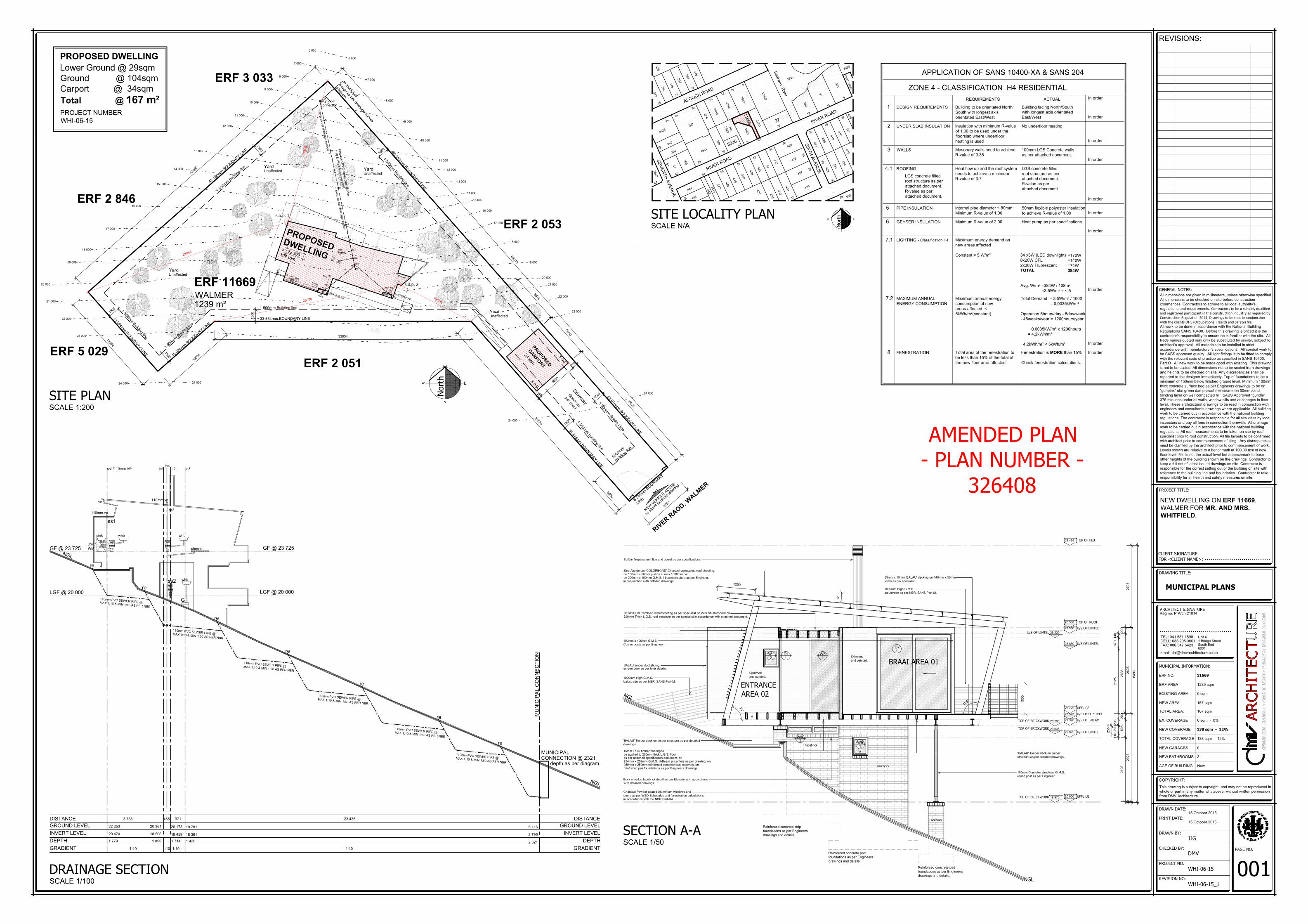
GROUND FLOOR PLAN
SCALE 1:50
North
s
w
E
A
T
ELECTRICAL LEGEND
LED Down lighter as per client specification
Single wall mounted light switch to be mounted
at 1300mm above uffl. All light switches to be
connected to dimmer switch
Stove isolator
Double wall mounted plug, top of socket to be
350mm above uffl
HANGING LIGHT ARMATURE POINT
prismatic diffuser suspended from ceiling.
1500 Long 2 tube fluorescent armature with
TV POINT AERIAL
WALL MOUNTED LIGHT ARMATURE POINT
GD
STARLIGHTS AS PER CLIENT
GARAGE DOOR CEILING MOUNTED MOTOR
EXTRACTOR CONNECTION PLUG @ 2100mm
ex
Pool light as per client
PL
GC
Gate Control Unit
Pre-paid Electricity meter
Main distribution board
WALL MOUNTED SPOTLIGHT ARMATURE POINT
SP
Telkom point
UP LIGHTER AS PER CLIENT
Daylight sensorDS
Under counter mounted track light
Foot light
Blank conduiting boxes
EF
HD
Electrical fence control box.
Hair dryer waterproof plug
PP
Internal spotlights as per specification.
Periscope plug as per specification.
i Intercom system.
LED strip light.
Double wall mounted plug, top of socket to be 1250mm
above uffl
KITCHEN 03
lightweight concrete floor, timber finish.
x 23 725
8sqm
OPEN PLAN LOUNGE 04
lightweight concrete floor, timber finish.
x 23 725
32sqm
MASTER BEDROOM 05
lightweight concrete floor, timber finish.
x 23 725
16sqm
OUTSIDE SHOWER 06
x 23 725
6sqm
DECK 07
timber deck
x 23 699
20sqm
timber deck
WALK IN DRESSER 08
lightweight concrete floor, timber finish.
x 23 725
6sqm
BRAAI AREA 09
timber deck
20sqm
ENTRANCE AREA 10
timber deck
x 23 725
LOO 11
concrete
floor,tf
x 23 725
2sqm
LOO 12
concrete
floor,tf
x 23 725
2sqm
ENTRANCE AREA 13
timber deck
x 22 911
Reinforced concrete
pad foundations
as per Engineers.
W1
2
W1
1
W8
1
D6
1
D2
1
D5
1
W7
1
W6
1
D4
1
D1
1
D9
1
W2
1
D8
1
W5
1
W4
1
D7
1
W3
1
D3
1
counter island
counter
stove pos.
sink
wm
dw
fridge pos.
duct
duct
BIC
1000 100 775 1000 100 2650 1825 1245 1725 300 1725 2550 200 1300 200 200
ss1/110mm vp
ss3/110mm vp
counter
wc
whb
shower
wc
whb
All dimensions are given in millimeters, unless otherwise specified.
All dimensions to be checked on site before construction
commences. Contractors to adhere to all local authority's
regulations and requirements. Contractors to be a suitably qualifiedand registered participant in the construction industry as required byConstruction Regulation 2014. Drawings to be read in conjunctionwith the clients OHS (Occupational Health and Safety) file.All work to be done in accordance with the National Building
Regulations SANS 10400. Before this drawing is priced it is the
contractor's responsibility to ensure he is familiar with the site. All
trade names quoted may only be substituted by similar, subject to
architect's approval. All materials to be installed in strict
accordance with manufacturer's specifications. All conduit work to
be SABS approved quality. All light fittings is to be fitted to comply
with the relevant code of practice as specified in SANS 10400:
Part O. All new work to be made good with existing. This drawing
is not to be scaled. All dimensions not to be scaled from drawings
and heights to be checked on site. Any discrepancies shall be
reported to the designer immediately. Top of foundations to be a
minimum of 150mm below finished ground level. Minimum 100mm
thick concrete surface bed as per Engineers drawings to be on
"gunplas" ubs green damp proof membrane on 50mm sand
blinding layer on well compacted fill. SABS Approved "gundle"
375 mic. dpc under all walls, window cills and at changes in floor
level. These architectural drawings to be read in conjunction with
engineers and consultants drawings where applicable. All building
work to be carried out in accordance with the national building
regulations. The contractor is responsible for all site visits by local
inspectors and pay all fees in connection therewith. All drainage
work to be carried out in accordance with the national building
regulations. All roof measurements to be taken on site by roof
specialist prior to roof construction. All tile layouts to be confirmed
with architect prior to commencement of tiling. Any discrepancies
must be clarified by the architect prior to commencement of work.
Levels shown are relative to a benchmark at 100.00 msl of new
floor level. Msl is not the actual level but a benchmark to base
other heights of the building shown on the drawings. Contractor to
keep a full set of latest issued drawings on site. Contractor is
responsible for the correct setting out of the building on site with
reference to the building line and boundaries. Contractor to take
responsibility for all health and safety measures on site.
GENERAL NOTES:
REVISIONS:
COPYRIGHT:
This drawing is subject to copyright, and may not be reproduced in
whole or part in any matter whatsoever without written permission
from DMV Architecture.
ERF NO:
EXISTING AREA:
NEW AREA:
TOTAL AREA:
NEW GARAGES
NEW BATHROOMS:
ERF AREA
EX. COVERAGE
NEW COVERAGE
AGE OF BUILDING
Unit 6
1 Bridge Street
Reg no. PrArch 21014
ARCHITECT SIGNATURE
...................................
South End
6001
TEL: 041 581 1590
CELL: 083 295 3601
FAX: 086 547 5423
email: [email protected]
MUNICIPAL INFORMATION:
TOTAL COVERAGE
PROJECT TITLE:
DRAWING TITLE:
................................
MUNICIPAL PLANS
NEW DWELLING ON ERF 11669,
WALMER FOR MR. AND MRS.
WHITFIELD.
CLIENT SIGNATURE
FOR <CLIENT NAME>:
REVISION NO.
PROJECT NO.
DRAWN BY:
DRAWN DATE:
CHECKED BY:
PRINT DATE:
PAGE NO.
DMV
WHI-06-15
WHI-06-15_1
JJG
003
1245200
x 23 699
A B C D E F G
A B C D E F G
1
2
3
4
1
2
3
4
A
18750
8200
18750
8200
1200
5150
1850
1875 3750 3750 3750 3750 1875
1850
5150
1200
187537503750375037501875
roof overhang
roof overhang roof overhang roof overhang
roof overhang
roof overhang
roof overhang roof overhang
9
5
°
8
5
°
9
5
°
5
4
°
1
2
1
°
8
4
°
9
6
°
BALAU timber duct sliding screen
door as per later details.
1000mm High G.M.S. balustrade as per
NBR, SANS Part-M.
Existing stone wall to be altered and made good as per on site Architect
instruction, affected stone to be stored on site until stone wall is to be
re-built..
Reinforced concrete filled facebrick stub column,
base plate position as indicated on Wet work plan
with accompanying details.
G.M.S. Structural steel structure as per Engineers
drawings and details.
Charcoal Powder coated Aluminium windows and
doors as per W&D Schedules and fenestration calculations
in accordance with the NBR Part-XA.
'BALAU' Timber deck on timber structure as per detailed drawings.
75mm x 50mm G.M.S. angles
bolted to steel structure as per
detailed drawings.
Light gauge steel concrete
walls as per attached document.
Built in cupboards and kitchen to be manufactured
and installed by specialist in accordance with
Architects drawings and instructions.
BALAU timber duct sliding screen
door as per later details.
1000mm High G.M.S.
balustrade as per NBR, SANS Part-M.
Built in fireplace unit flue and
cowel as per specifications.
100mm x 100mm G.M.S.
Corner posts as per Engineer.
1000mm High G.M.S. balustrade as per
NBR, SANS Part-M.
Existing stone wall to be
altered and made good as per
on site Architect instruction,
affected stone to be stored on
site until stone wall is to be
re-built..
Reinforced concrete filled
facebrick wall, as per
accompanying wetwork plan
and details.
Charcoal Powder coated
Aluminium windows and
doors as per W&D Schedules
and fenestration calculations
in accordance with the NBR
Part-XA.
Built in cupboards and kitchen to be
manufactured and installed by specialist in
accordance with Architects drawings and
instructions.
100mm x 100mm G.M.S.
Corner posts as per Engineer.
1200
4585
2180
350
1970
4
7
4
6
6
1
°
5°
500019000
170 1131245 1075 112
300
100
550
100
1600
100
350
100
1450
100
1260
80
2610
350
360
500
590
1000 775 1825 100 1825 1825 100 1825
550
100
450
1800
100
5050
100
1250
1900
1900
900
1925
100
1125
3600
95021401385
2500
850
3801001345100
380100222
900222
100
600
100
2360
90
1000
300
600
900
150
300
900
100
100
1250
100
9002475900
100
450
100
1219
581
1758 11769
100mm x 100mm G.M.S.
Corner posts as per Engineer.
400
500
500
x 600
500 x 600
4585 x
2640
1250 x 2640
1663 x 2640
2193 x 2640
600 x 2640
1000 x 2500
2105 x 2500
900 x 2150
900 x 2125
300 x 2500
1775 x 2500
1900 x 2
500
1150 x 2640
2394 x 2640
2105 x 2500
6360 x
2640
2105
counter
To connect to two
way switch downstairs.
2w
DS
DS
DS
DS
exexex
To connect to two
way switch at carport.
300745300
300
5169
AMENDED PLAN
- PLAN NUMBER -
326408
225
1000
675
600
15 October 2015
15 October 2015
0 sqm
167 sqm
167 sqm
0
3
1239 sqm
0 sqm - 0%
New
138 sqm - 12%
138 sqm - 12%
11669
Fenestration Schedule
# Sector
Description
Width
Height
Area u SHGC Total Cu P H P/H Lu P/H e AxSxE AVev
S
Wispeco Double Glaze :6.38mm PVB + 12mm + 6.38mm
1695 2500 4.24 3.67 0.51 15.55 1927.2 3000 0.64 0.6 0.31 0.67 1.39
S
Wispeco Casement 38 : 6.38mm Glass
200 2500 0.5 5.78 0.37 2.89 3927.65 3000 1.31 1.3 0.21 0.04 0.36
W
Wispeco Double Glaze :6.38mm PVB + 12mm + 6.38mm1820 2500 4.55 3.67 0.51 16.7 550 3000 0.18 0.15 1.18 2.74 1.82
W
Wispeco Double Glaze :6.38mm PVB + 12mm + 6.38mm
1170 2640 3.09 3.67 0.51 11.34 1100 2978 0.37 0.35 0.95 1.5 1.12
N
Wispeco Double Glaze :6.38mm PVB + 12mm + 6.38mm
4505 2640 11.89 3.67 0.51 43.64 2335.98 2978 0.78 0.7 0.28 1.7 2.71
N
Wispeco Double Glaze :6.38mm PVB + 12mm + 6.38mm6280 2640 16.58 3.67 0.51 60.84 2320.33 2978 0.78 0.7 0.28 2.37 3.77
Fenestration Summary
Zone Cu CSHGC Nett Floor Area Total Glazed Area
Glazing %
Conductance SHGC
15% 152.85 14.19
4 1.4 0.13 109.18 40.85 37.41 150.96 9.01
Calculate
Compliant Compliant
FENESTRATION CALCULATIONS
iii
900
Intercom system by specialist at gate as per Architect / Client
agreement.
ss2
G
wc
whb
wc
whb
sink
dw /
wm
wc
whb
110mm vp ss3 110mm vp ss1
shower
shower
All dimensions are given in millimeters, unless otherwise specified.
All dimensions to be checked on site before construction
commences. Contractors to adhere to all local authority's
regulations and requirements. Contractors to be a suitably qualifiedand registered participant in the construction industry as required byConstruction Regulation 2014. Drawings to be read in conjunctionwith the clients OHS (Occupational Health and Safety) file.All work to be done in accordance with the National Building
Regulations SANS 10400. Before this drawing is priced it is the
contractor's responsibility to ensure he is familiar with the site. All
trade names quoted may only be substituted by similar, subject to
architect's approval. All materials to be installed in strict
accordance with manufacturer's specifications. All conduit work to
be SABS approved quality. All light fittings is to be fitted to comply
with the relevant code of practice as specified in SANS 10400:
Part O. All new work to be made good with existing. This drawing
is not to be scaled. All dimensions not to be scaled from drawings
and heights to be checked on site. Any discrepancies shall be
reported to the designer immediately. Top of foundations to be a
minimum of 150mm below finished ground level. Minimum 100mm
thick concrete surface bed as per Engineers drawings to be on
"gunplas" ubs green damp proof membrane on 50mm sand
blinding layer on well compacted fill. SABS Approved "gundle"
375 mic. dpc under all walls, window cills and at changes in floor
level. These architectural drawings to be read in conjunction with
engineers and consultants drawings where applicable. All building
work to be carried out in accordance with the national building
regulations. The contractor is responsible for all site visits by local
inspectors and pay all fees in connection therewith. All drainage
work to be carried out in accordance with the national building
regulations. All roof measurements to be taken on site by roof
specialist prior to roof construction. All tile layouts to be confirmed
with architect prior to commencement of tiling. Any discrepancies
must be clarified by the architect prior to commencement of work.
Levels shown are relative to a benchmark at 100.00 msl of new
floor level. Msl is not the actual level but a benchmark to base
other heights of the building shown on the drawings. Contractor to
keep a full set of latest issued drawings on site. Contractor is
responsible for the correct setting out of the building on site with
reference to the building line and boundaries. Contractor to take
responsibility for all health and safety measures on site.
GENERAL NOTES:
REVISIONS:
COPYRIGHT:
This drawing is subject to copyright, and may not be reproduced in
whole or part in any matter whatsoever without written permission
from DMV Architecture.
ERF NO:
EXISTING AREA:
NEW AREA:
TOTAL AREA:
NEW GARAGES
NEW BATHROOMS:
ERF AREA
EX. COVERAGE
NEW COVERAGE
AGE OF BUILDING
Unit 6
1 Bridge Street
Reg no. PrArch 21014
ARCHITECT SIGNATURE
...................................
South End
6001
TEL: 041 581 1590
CELL: 083 295 3601
FAX: 086 547 5423
email: [email protected]
MUNICIPAL INFORMATION:
TOTAL COVERAGE
PROJECT TITLE:
DRAWING TITLE:
................................
COSTING PLANS
NEW DWELLING ON ERF 11669,
WALMER FOR MR. AND MRS.
WHITFIELD.
CLIENT SIGNATURE
FOR <CLIENT NAME>:
REVISION NO.
PROJECT NO.
DRAWN BY:
DRAWN DATE:
CHECKED BY:
PRINT DATE:
PAGE NO.
DMV
WHI-06-15
WHI-06-15_1
JJG
004
100mm Diameter structural G.M.S. round post as per Engineer.
8493
2923
2835
2705
2125
598
200
30
2635
200
140
370
2125
203
285
110
30
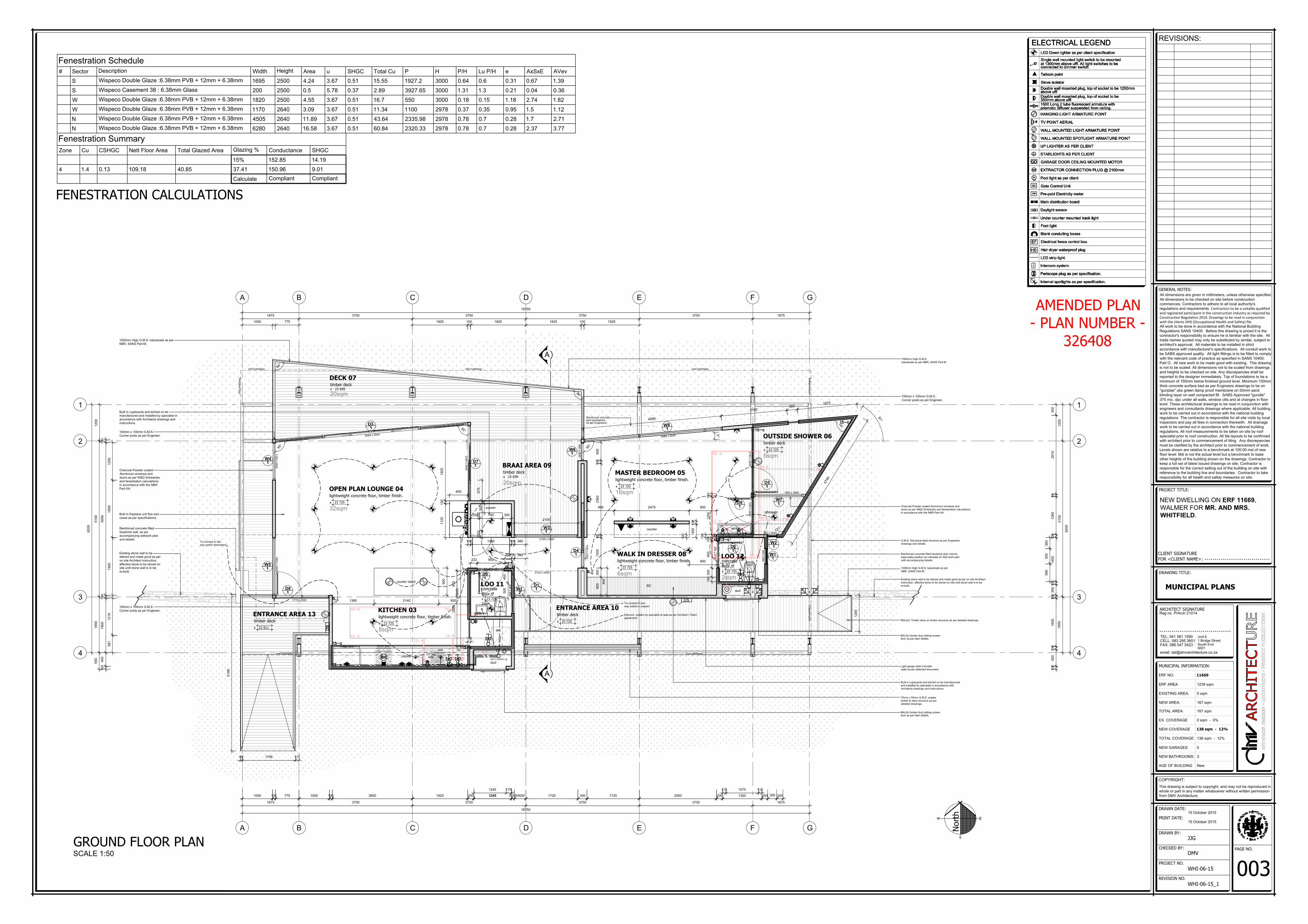
20 000 UFFL LG
23 725 UFFL GF
22 925 U/S OF LINTEL
25 850 U/S OF LINTEL
28 465 TOP OF FLU
26 560 TOP OF ROOF
26 360 U/S OF LINTEL
26 220U/S OF LINTEL
23 525 U/S OF LG STEEL
23 320
TOP OF BRICKWORK
23 290
TOP OF BRICKWORK
23 035
255
TOP OF BRICKWORK19 970
U/S OF I-BEAM
8493
2923
2835
2705
2125
598
200
30
2635
200
140
370
2125
203
285
110
30
20 000 UFFL LG
23 725 UFFL GF
22 925 U/S OF LINTEL
25 850 U/S OF LINTEL
28 465 TOP OF FLU
26 560 TOP OF ROOF
26 360 U/S OF LINTEL
26 220U/S OF LINTEL
23 525 U/S OF LG STEEL
23 320
TOP OF BRICKWORK
23 290
TOP OF BRICKWORK
23 035
255
TOP OF BRICKWORK19 970
U/S OF I-BEAM
NGL
NGL
NGL
NGL
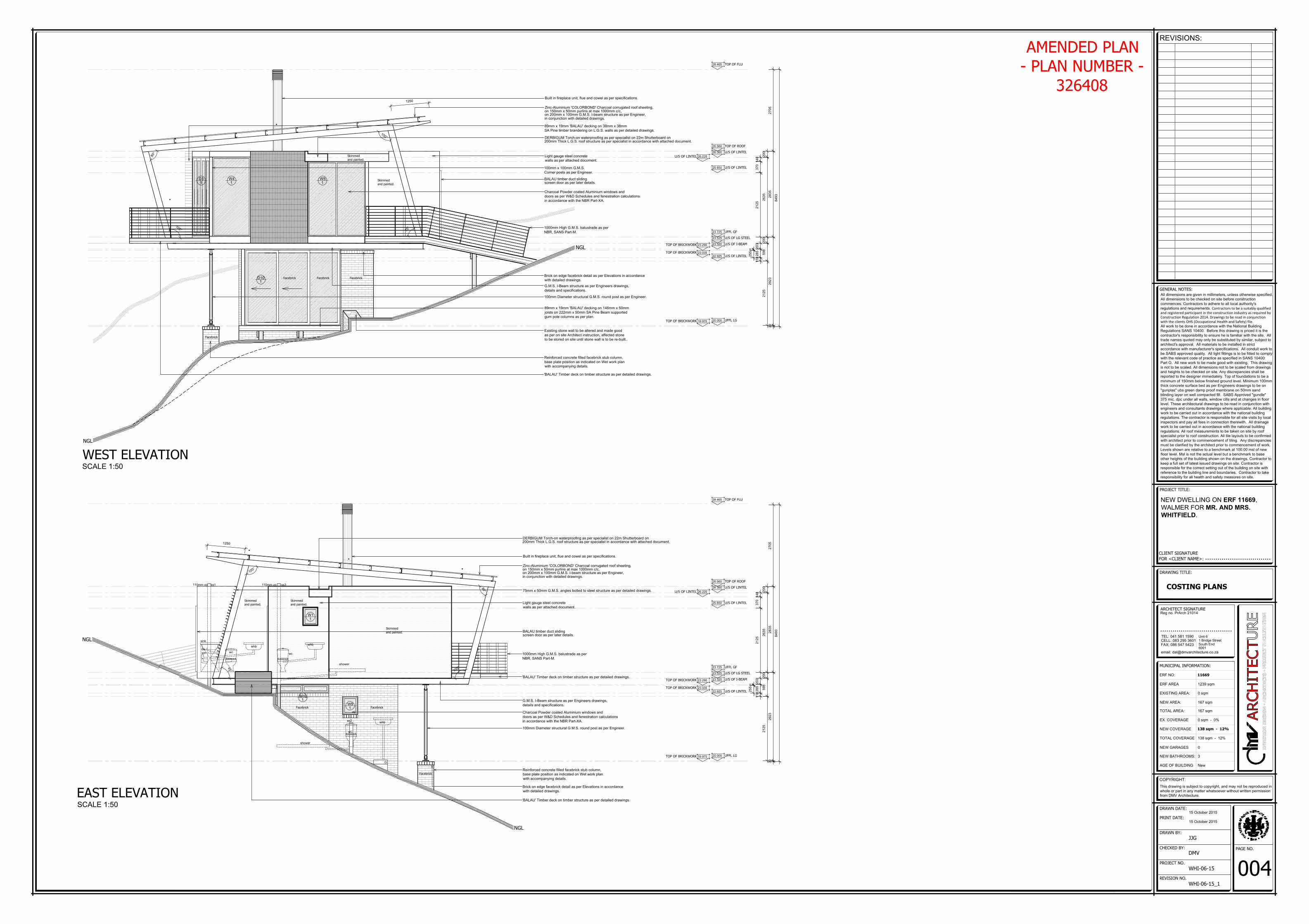
WEST ELEVATION
SCALE 1:50
EAST ELEVATION
SCALE 1:50
Facebrick Facebrick Facebrick
Facebrick
Facebrick Facebrick
Facebrick
Skimmed
and painted.
Skimmed
and painted.
Skimmed
and painted.
Skimmed
and painted.
1
0
0
°
8
0
°
7
5
°
1
0
5
°
8
0
°
1
0
0
°
1
0
5
°
7
5
°
100mm Diameter structural G.M.S. round post as per Engineer.
89mm x 19mm 'BALAU' decking on 146mm x 50mm
joists on 222mm x 50mm SA Pine Beam supported
gum pole columns as per plan.
Reinforced concrete filled facebrick stub column,
base plate position as indicated on Wet work plan
with accompanying details.
Reinforced concrete filled facebrick stub column,
base plate position as indicated on Wet work plan
with accompanying details.
Charcoal Powder coated Aluminium windows and
doors as per W&D Schedules and fenestration calculations
in accordance with the NBR Part-XA.
Charcoal Powder coated Aluminium windows and
doors as per W&D Schedules and fenestration calculations
in accordance with the NBR Part-XA.
G.M.S. I-Beam structure as per Engineers drawings,
details and specifications.
G.M.S. I-Beam structure as per Engineers drawings,
details and specifications.
Brick on edge facebrick detail as per Elevations in accordance
with detailed drawings.
Brick on edge facebrick detail as per Elevations in accordance
with detailed drawings.
1000mm High G.M.S. balustrade as per
NBR, SANS Part-M.
1000mm High G.M.S. balustrade as per
NBR, SANS Part-M.
on 200mm x 100mm G.M.S. I-beam structure as per Engineer,
Zinc-Aluminium 'COLORBOND' Charcoal corrugated roof sheeting,
on 150mm x 50mm purlins at max 1000mm c/c,
in conjunction with detailed drawings.
on 200mm x 100mm G.M.S. I-beam structure as per Engineer,
Zinc-Aluminium 'COLORBOND' Charcoal corrugated roof sheeting,
on 150mm x 50mm purlins at max 1000mm c/c,
in conjunction with detailed drawings.
Built in fireplace unit, flue and cowel as per specifications.
Built in fireplace unit, flue and cowel as per specifications.
1250
1250
BALAU timber duct sliding
screen door as per later details.
BALAU timber duct sliding
screen door as per later details.
100mm x 100mm G.M.S.
Corner posts as per Engineer.
89mm x 19mm 'BALAU' decking on 38mm x 38mm
SA Pine timber brandering on L.G.S. walls as per detailed drawings.
75mm x 50mm G.M.S. angles bolted to steel structure as per detailed drawings.
DERBIGUM Torch-on waterproofing as per specialist on 22m Shutterboard on
200mm Thick L.G.S. roof structure as per specialist in accordance with attached document.
DERBIGUM Torch-on waterproofing as per specialist on 22m Shutterboard on
200mm Thick L.G.S. roof structure as per specialist in accordance with attached document.
Existing stone wall to be altered and made good
as per on site Architect instruction, affected stone
to be stored on site until stone wall is to be re-built..
Light gauge steel concrete
walls as per attached document.
Light gauge steel concrete
walls as per attached document.
'BALAU' Timber deck on timber structure as per detailed drawings.
'BALAU' Timber deck on timber structure as per detailed drawings.
'BALAU' Timber deck on timber structure as per detailed drawings.
D3
1
W4
1
W5
1
D10
1
W1
1
W9
1
AMENDED PLAN
- PLAN NUMBER -
326408
15 October 2015
15 October 2015
0 sqm
167 sqm
167 sqm
0
3
1239 sqm
0 sqm - 0%
New
138 sqm - 12%
138 sqm - 12%
11669
Skimmed
and painted.
W10
1
All dimensions are given in millimeters, unless otherwise specified.
All dimensions to be checked on site before construction
commences. Contractors to adhere to all local authority's
regulations and requirements. Contractors to be a suitably qualifiedand registered participant in the construction industry as required byConstruction Regulation 2014. Drawings to be read in conjunctionwith the clients OHS (Occupational Health and Safety) file.All work to be done in accordance with the National Building
Regulations SANS 10400. Before this drawing is priced it is the
contractor's responsibility to ensure he is familiar with the site. All
trade names quoted may only be substituted by similar, subject to
architect's approval. All materials to be installed in strict
accordance with manufacturer's specifications. All conduit work to
be SABS approved quality. All light fittings is to be fitted to comply
with the relevant code of practice as specified in SANS 10400:
Part O. All new work to be made good with existing. This drawing
is not to be scaled. All dimensions not to be scaled from drawings
and heights to be checked on site. Any discrepancies shall be
reported to the designer immediately. Top of foundations to be a
minimum of 150mm below finished ground level. Minimum 100mm
thick concrete surface bed as per Engineers drawings to be on
"gunplas" ubs green damp proof membrane on 50mm sand
blinding layer on well compacted fill. SABS Approved "gundle"
375 mic. dpc under all walls, window cills and at changes in floor
level. These architectural drawings to be read in conjunction with
engineers and consultants drawings where applicable. All building
work to be carried out in accordance with the national building
regulations. The contractor is responsible for all site visits by local
inspectors and pay all fees in connection therewith. All drainage
work to be carried out in accordance with the national building
regulations. All roof measurements to be taken on site by roof
specialist prior to roof construction. All tile layouts to be confirmed
with architect prior to commencement of tiling. Any discrepancies
must be clarified by the architect prior to commencement of work.
Levels shown are relative to a benchmark at 100.00 msl of new
floor level. Msl is not the actual level but a benchmark to base
other heights of the building shown on the drawings. Contractor to
keep a full set of latest issued drawings on site. Contractor is
responsible for the correct setting out of the building on site with
reference to the building line and boundaries. Contractor to take
responsibility for all health and safety measures on site.
GENERAL NOTES:
REVISIONS:
COPYRIGHT:
This drawing is subject to copyright, and may not be reproduced in
whole or part in any matter whatsoever without written permission
from DMV Architecture.
ERF NO:
EXISTING AREA:
NEW AREA:
TOTAL AREA:
NEW GARAGES
NEW BATHROOMS:
ERF AREA
EX. COVERAGE
NEW COVERAGE
AGE OF BUILDING
Unit 6
1 Bridge Street
Reg no. PrArch 21014
ARCHITECT SIGNATURE
...................................
South End
6001
TEL: 041 581 1590
CELL: 083 295 3601
FAX: 086 547 5423
email: [email protected]
MUNICIPAL INFORMATION:
TOTAL COVERAGE
PROJECT TITLE:
DRAWING TITLE:
................................
COSTING PLANS
NEW DWELLING ON ERF 11669,
WALMER FOR MR. AND MRS.
WHITFIELD.
CLIENT SIGNATURE
FOR <CLIENT NAME>:
REVISION NO.
PROJECT NO.
DRAWN BY:
DRAWN DATE:
CHECKED BY:
PRINT DATE:
PAGE NO.
DMV
WHI-06-15
WHI-06-15_1
JJG
005
84
93
29
23
28
35
27
05
21
25
59
82
00
30
26
35
20
0
14
03
70
21
25
20
32
85
11
0
30
20 000 UFFL LG
23 725 UFFL GF
22 925 U/S OF LINTEL
25 850 U/S OF LINTEL
28 465 TOP OF FLU
26 560 TOP OF ROOF
26 360 U/S OF LINTEL
26 220U/S OF LINTEL
23 525 U/S OF LG STEEL
23 320
TOP OF BRICKWORK
23 290
TOP OF BRICKWORK23 035
25
5
TOP OF BRICKWORK19 970
U/S OF I-BEAM
84
93
29
23
28
35
27
05
21
25
59
82
00
30
26
35
20
0
14
03
70
21
25
20
32
85
11
0
30
20 000 UFFL LG
23 725 UFFL GF
22 925 U/S OF LINTEL
25 850 U/S OF LINTEL
28 465 TOP OF FLU
26 560 TOP OF ROOF
26 360 U/S OF LINTEL
26 220U/S OF LINTEL
23 525 U/S OF LG STEEL
23 320
TOP OF BRICKWORK23 290
TOP OF BRICKWORK
23 035
25
5
TOP OF BRICKWORK
19 970
U/S OF I-BEAM
NGL
NGL
NGL
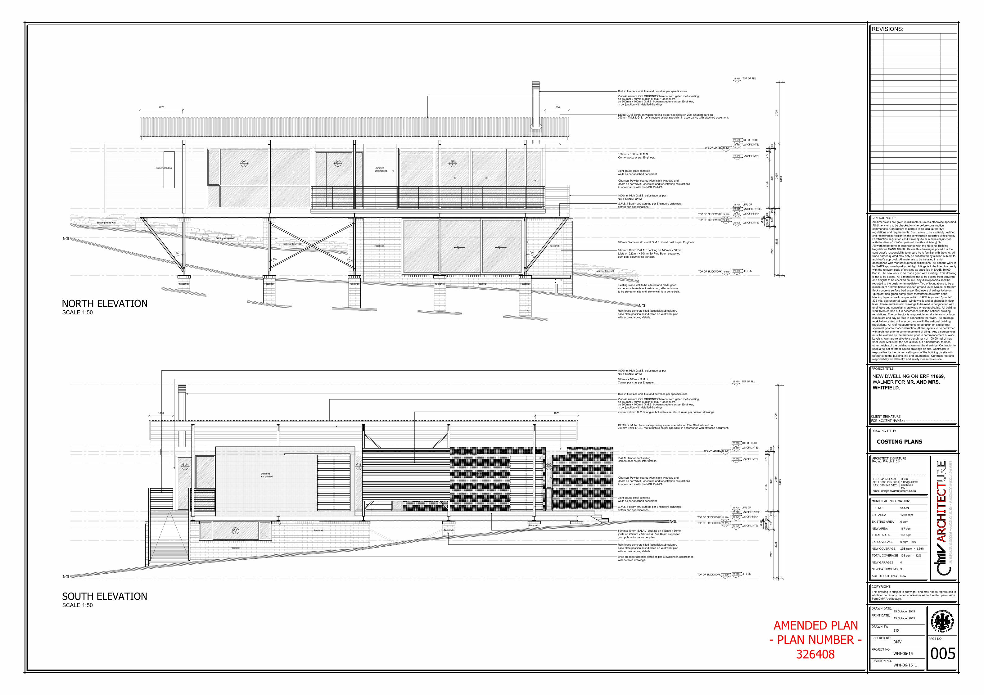
NGLNORTH ELEVATION
SCALE 1:50
SOUTH ELEVATION
SCALE 1:50
Facebrick Facebrick Facebrick Facebrick Facebrick
Facebrick Facebrick
Facebrick
Facebrick
Facebrick
Timber cladding Skimmed
and painted.
Existing stone wall
Existing stone wall
Existing stone wall
Existing stone wall
3
8
°
3
8
°
6
2
°6
2
°
1000mm High G.M.S. balustrade as per
NBR, SANS Part-M.
10501875
18751050
Built in fireplace unit, flue and cowel as per specifications.
Built in fireplace unit, flue and cowel as per specifications.
on 200mm x 100mm G.M.S. I-beam structure as per Engineer,
Zinc-Aluminium 'COLORBOND' Charcoal corrugated roof sheeting,
on 150mm x 50mm purlins at max 1000mm c/c,
in conjunction with detailed drawings.
on 200mm x 100mm G.M.S. I-beam structure as per Engineer,
Zinc-Aluminium 'COLORBOND' Charcoal corrugated roof sheeting,
on 150mm x 50mm purlins at max 1000mm c/c,
in conjunction with detailed drawings.
DERBIGUM Torch-on waterproofing as per specialist on 22m Shutterboard on
200mm Thick L.G.S. roof structure as per specialist in accordance with attached document.
DERBIGUM Torch-on waterproofing as per specialist on 22m Shutterboard on
200mm Thick L.G.S. roof structure as per specialist in accordance with attached document.
Light gauge steel concrete
walls as per attached document.
Light gauge steel concrete
walls as per attached document.
100mm x 100mm G.M.S.
Corner posts as per Engineer.
100mm x 100mm G.M.S.
Corner posts as per Engineer.
BALAU timber duct sliding
screen door as per later details.
Charcoal Powder coated Aluminium windows and
doors as per W&D Schedules and fenestration calculations
in accordance with the NBR Part-XA.
Charcoal Powder coated Aluminium windows and
doors as per W&D Schedules and fenestration calculations
in accordance with the NBR Part-XA.
1000mm High G.M.S. balustrade as per
NBR, SANS Part-M.
Brick on edge facebrick detail as per Elevations in accordance
with detailed drawings.
G.M.S. I-Beam structure as per Engineers drawings,
details and specifications.
G.M.S. I-Beam structure as per Engineers drawings,
details and specifications.
100mm Diameter structural G.M.S. round post as per Engineer.
89mm x 19mm 'BALAU' decking on 146mm x 50mm
joists on 222mm x 50mm SA Pine Beam supported
gum pole columns as per plan.
89mm x 19mm 'BALAU' decking on 146mm x 50mm
joists on 222mm x 50mm SA Pine Beam supported
gum pole columns as per plan.
Existing stone wall to be altered and made good
as per on site Architect instruction, affected stone
to be stored on site until stone wall is to be re-built..
Reinforced concrete filled facebrick stub column,
base plate position as indicated on Wet work plan
with accompanying details.
Reinforced concrete filled facebrick stub column,
base plate position as indicated on Wet work plan
with accompanying details.
Facebrick
Skimmed
and painted.
Skimmed
and painted.
Timber cladding
W8
1
W3
1
D3
1
D8
1
D1
1
W2
1
75mm x 50mm G.M.S. angles bolted to steel structure as per detailed drawings.
AMENDED PLAN
- PLAN NUMBER -
326408
Facebrick
W11
1
15 October 2015
15 October 2015
0 sqm
167 sqm
167 sqm
0
3
1239 sqm
0 sqm - 0%
New
138 sqm - 12%
138 sqm - 12%
11669