Embed Size (px)
Citation preview

LL.
ABSTRACT
Service experience indicates that the probability of flaw propagation into
the base metal underneath clad in PWR systems is remote. However, a two
step ultrasonic inspection technique was developed in preference to a single
step technique to provide maximum sensitivity and depth definition of any
possible flaw propagation.
Acceptance criteria for continued operation will be within the limits of
Section XI of the ASME Code with its built in safety factors viz. 3 on
stress and 10 on flaw size.
*8111190005 780113 * PDR ADOCK 05000286 P PDR

'INTROBUCTION
Service experience with PWR systems indicate that flaws in stainless steel weld clad on carbon or low alloy steel will not propagate into the base metal underneath (Attachment I). However, it was requested that an ultrasonic method be developed to provide a means of in-service inspection of clad flaws to monitor possible growth into base metal. These flaws could then be evaluated, using rules defined in Section XI of the ASME Code to determine if they would affect the structural integrity of the vessesls.
ULTRASONIC INSPECTION PROGRAM
In order to obtain the best possible linear response and therefore the best flaw depth definition, a two step ultrasonic procedure has been developed and is described in Attachment II.
Step I of this ultrasonic procedure will accurately define flaws to a depth of 3/8 inch and will be used for the in-service inspections. Since the maximum clad thickness in the surveillance areas is 1/4 inch, Step I will define a flaw propagation into the base metal up to 1/8 inch. In the event that flaws exceed 3/8" then Step II will be used to further define depths up to 3/4 inch.
EVALUATION PROGRAM
The results of the ultrasonic inspections will be evaluated in accordance with the rules of Section XI of the ASME Code as follows:
1. If no flaws are found which propagate into base metal no further evaluation is required.
2. If flaws are found which propagate into the base metal,they will first be evaluated to section XI IWB-3512.1 and, therefore, must stay within the limits of IWB-3512.1 (a). Justification is given in Attachment III. If no flaw depths exceed these limits no further evaluation will be required.
3. The critical flaw parameters with respect to flaw location may be calculated as outlined in Section XI IWB-3600. Attachment IV gives the calculations for the critical flaw sizes at the location of maximum stress in the surveillance area using specified cyclic duty.
- 2

If plant experience has not exceeded specified cyclic duty these
flaw aspect ratios may be used to evaluate all flaws that may have
propagated into base metal beyond those listed in (2) above.
4. Larger flaws than those permitted by (3) above may be justified
by fracture mechanics analyses on a case by case basis dependent
an location, stress, and cyclic experience of the plant.
INSPECTION AND EVALUATION PROCEDURE
The ultrasonic inspection and evaluation procedures will be in accordance
with MPT-61 and NPT-81 respectively, and are given in Appendix I of this
report.
CONCLUS IONS
1. An ultrasonic inspection procedure has been developed which
will accurately define flaw depths greater than the critical flaw
s-ize.
2. Fracture mechanics analysis have been made to determine critical
flaw size in the highest stress region.
3. Justification for continued operation will be determined by
fracture mechanics analyses calculated using methods defined in
Section XI of the ASME Code.
- 3 -

APPENDIX I
INSPECTION AND EVALUATION PROCEEDURE NPT-61 AND NPT-81

Issue. 1
9129/75
C. Galyen G. Hughes
Changed
2/14/77 2 9/28/77 3
Pr ss Specification NUCL POW m. COMPONENTS
'METHOD OF SHEAR WAVE ULTRASONIC CLADDING SURVEILLANCE
NPT-61 SPage 1 of 5
PURPOSE: Ultrasonic surveillance procedure for periodically determining the extent and possible growth of clad cracking in designated areas of steam generator, channel heads. The procedure includes the means to measure clad thickness as a .baseline process and the fixturing necessary to duplicate the test program periodically.
QUALIFICATION OF PERSONNEL: Personnel performing the examination under this procedure shall be qualified in accordance with ASNT-TC-A, Supplement "C", Level II or III.
OPERATIONS:
Part I: Clad Measurement:
1. Measure clad thickness in the approximate center of designated areas using the procedure detailed below (Ref. Automation Industries' Report #TR-71-24A).
2. Record clad thickness determined in each area. 3. Clean and check clad surfaces in examination areas.
Equipment:
a) UM 775 instrument "Automation" (must fit through 18 inch manway). b) 1ON db. pulser/receiver. c) Search unit fixture 57A6878.
57A3615 SIZ transmitter search unit. 57A2796 SIL receiver search unit.
d) Reference standard S/N 1. e) Glycerine for couplant.
Calibration:
a) Turn on instrument and allow proper warm up. b) Connect cables from transmitter and receiver search units in fixture
57A6878 to their respective jacks on the 1ON db. pulser/receiver. c). Adjust the instrument controls to the following preliminary settings:
UM 775 1ON db
1) Sweep Delay 1) Sens. db control - 16 Push Button 5-50 Vernier - Max. (ccw)
2) Sweep Range 2) Reject 1/4 cw Push Button - 1 Material Vernier - Mid Range
3) Vertical - Adjust to locate 3) Test - Through baseline at 0 vertical position 4) Altn.- Max. (ccw) 4) Pulse Tune - Max. (ccw) 5) Rate - Max. (cw) 5) Pulse Length - Min. (cw) 6) Horizontal - Adjust to center 6) Freq. - 2.25 MHz
baseline on scope screen 7) Mode - Out
Westinghouse Electic Corporaflon Tampa Division Nuclear Energy Systems Tampa. Florida. U. S. A.
NPT-61 Page 1 of 5
1 _ , m
era-

NPT-61 Page 2
,,Process Specification NUCLEAR POWER COMPONENTS
METHOD OF SHEAR WAVE ULTRASONIC CLADDING SURVEILLANCEof 5
d) Position transigate switch~to "Off". e) Apply couplant (glycerine/water mix) to reference block, place inspection
fixture on reference block and locate signal from block front surface. f) Position front surface signal near left side of Reflectoscope screen
and mark location on screen with grease pencil. g) Manipulate fixture and adjust sensitivity db control as required until
signal is obtained from reference hole A. Position front surface signal at mark obtained in (f) above, using sweep delay Vernier. Mark location of hole "A" signal on Reflectoscope screen with grease pencil.
h) Repeat step (g) for reference holes B, C and D, and mark the respective locations on the Reflectoscope screnen The reference marks. from holes
A-D represent cladding thickness of 0.20", 0.25", 0.30" and 0.35", respectively.
IPart II: Surveillance Procedure - 1/8 inch-l/2 inch range
Equipment:
a) UM 775 Reflectoscope (Automation) b) 5N Weld Pulser/Receiver . c) Alarm and recording module (Transigate) d) Westinghouse Immersion/contact search fixture 20 incident angle e) 1.0 MH 1-1/8" dia., heavy backing, SIZ transducer, Style #57A3453 f) Scanning fixture (WTD) g) .X-Y Recorder h) Clad Channel Head reference block with 3/4 in. long by 1/8 in., 1/4 in.,
3/8 in., and .450 deep Elox notches. i) Couplant: 2 parts glycerine, 1 part water, 4-5 drops wetting agent per
pint.
Calibration:
a) b)
Reject off Set response from the 3/8" deep Elox notch to 80% of full screen height
(FSH) note and record response from the 1/4" and 1/8" deep notches
should be approximately 50% + 5% (FSH) and 25% + 5% (FSH), respectively. (Note response from .450 - 90% deep notch.)
Procedure:
1. Set "feet" on search unit fixture as follows:
a) Place assembled "empty" search unit fixture on 0.040-0.045 inch thick shim on flat surface.
b) Adjust feet to touch flat surface.
2. Fill fixture with water and pressurize so that approximately 75-80% of flexible bladder width touches flat surface on which four "feet" are resting.
3. Mount scanning fixture including search unit on reference block so that sound beam is projected perpendicular to notches.
Issue 1
9/29/75
C. Galyen G. Hughes
Changed
2 2/14/77 3 )/28/77
NPT-61 Page 2 of 5
Wesfnghouse Electric Corporaton Tampa Oivision Nuclear Energy Systems Tampa. Florida. U. S. A.
.4
I
I

Issue 1
C. Galyen G. Hughes
Changed
2/14/77 2 9/28/77 3
-I-
-.--
Props Specification NUCLM K POTIR COMPONENTS
METHOD OF SHEAR WAVE ULTRASONIC CLADDING SURVEILLANCE
NPT-61
I Page 3 of 5
4. Set response from 3/8" deep notch to 80% of full screen height CFSH).
Note response from 1/4" and 1/8" deep notches.
5. Set recording gate "start" at peak point of 1/8" notch indication
minus 1" of test metal distance. Set recording gate "END" at peak
point of 1/8" notch indication plus 3/4" of test metal distance.
6. Connect data potentiometer of scanner (5 inch scan length) to Y
coordinate of X-Y recorder. Connect amplitude response to X coordinate
of X-Y recorder.
7. Record calibration by scanning across reference block at appropriate
(approx. 1/4") increments toiretord maximum responses and locations
from reference notches. Set pen manually to duplicate scan spacings.
8. Place scanner on selected area of channel head. Set search unit on
left hand edge of area to be scanned. Move search unit to top of
scan (5") and return to bottom of scan length. Move search unit 3/4"
to right, move pen on recorder 3/4" and repeat 5" scan. Repeat process
at 3/4" increments until specified width (circumferential direction on
channel head) of selected area has been traversed.
9. Maintain records for comparison with periodic in-service recordings
made in the same .manner as described.
10. Clean and identify areas.
11. Follow the above procedure on channel head by placing the scanning
fixture "feet" in drilled holes for each position.
12. Record U.T. results for each area scanned on channel head.
13. Maintain records for comparison with periodic in-service recordings
made in the same manner as described.
IPart III: Surveillance Procedure - 1/2 inch-3/4 inch range
Equipment:
a) UM 775 Reflectoscope (Automation) b) 5N Weld Pulser/Receiver c) Alarm and recording module (Transigate) d) Westinghouse Inmersion/contact search fixture 160 + 1
° -00 incident angle.
e) 1.0 MH 1-1/8" dia., heavy backing, SIZ transducer, Style #57A3453 Z f) Scanning fixture (WTD) g) X-Y Recorder h) Clad Channel Head reference block with 3/4 in. long by 1/2", 5/8", and
3/4" deep Elox notches. i) Couplant: 2 parts glycerine, 1 part water, 4-5 drops wetting agent per
pint
Westinghouse Electric Corporation Tampa Division Nuclear Energy Systems Tampa. Florida. U. S. A.
NPT-61 Page 3 of 5

NPT-61 1,_ ./ . 9 4
* D.ocess Specification
NUCLEAR POWER COMPONENTS
METHOD OF SHEAR WAVE ULTRASONIC CLADDING SURVEILLANCE
rage~u
.Calibration:
a) Reject off b) Set response from the 3/4" deep Elox notch to 95%
of full screen height
(FSH) note and record response from the 1/2" and 5/8" deep notches - should
be approximately 45% (FSH) and 70% (FSH), respectively.
(Note response from 0.450" notch.)
Procedure:
1. Set "feet" on search unit fixture as follows:
a) Place assembled "empty" search unit fixture on 0.040-0.045 inch thick
shim on flat surface.
b) Adjust feet to touch flat surface.
2. Fill fixture with water and pressurize so that approximately 75-80% of
flexible bladder width touches flat surface on which four "feet" are
resting.
3. Mount scanning fixture including search unit on reference block so that
sound beam is projected perpendicular to notches.
4. Set response from 3/4" deep notch to 95% of full screen height (FSH).
(Note response from 1/2" and 5/8" deep notches.)5
5. Set recording gate "start" 1" of test metal distance.
notch indication plus 3/4"
at peak point of 1/2" notch indication minus Set recording gate "END" at peak point of 1/2"
of test metal distance.
6. Connect data potentiometer of scanner (5 inch scan length) to Y coordinate
of X-Y recorder. Connect amplitude response to X coordinate of X-Y
recorder.
7. Record calibration by scanning across reference block at appropriate
(approx. 1/4") increments to record maximum responses and locations from
reference notches. Set pen manually to duplicate scan spacings.
8. Place scanner on selected area of channel head. Set search unit on
left hand edge of area to be scanned. Move search unit to top of scan
(5") and return to bottom of scan length. Move search unit 3/4" to right,
move pen on recorder 3/4" and repeat 5" scan. Repeat process at 3/4"
increments until specified width (circumferential direction on channel
head) of selected area has been traversed.
9. Maintain records for comparison with periodic in-service recordings
made in the same manner as described.
NPT-61 Page 4 of 5
Westinghouse Electric Corporation Tampa Division Nuclear Energy Systems Tampa. Florida. U. S. A.
T
Issue 1 9/29/75
C. Galyen
G. Hughes
Changed
2 2/14/77
3 9/28/77

Issue 1
9/29/75
\ Galyen G. Hughes
Changed
9/28/77 3
Pro ss Specification NUCLEAR POwR COMPONENTS
METHOD OF SHEAR WAVE ULTRASONIC CLADDING SURVEILLANCENPT-61 Page 5 of 5
10. Clean and identify areas.
11. Follow the above procedure on channel head by placing the scanning fixture "feet" in drilled holes for each position.
12. Record U.T. results for each area scanned on channel head.
13. Maintain records for comparison with periodic in-service recordings made in the same manner as described.
IWeslnghouse Electic Corporation Tampa Division Nuclear Energy Systems Tampa. Florida. U. S. A.
NPT-61 Page 5 of 5

PR R" L Pro~sj Specification E , MAPROQEDURE FO RASON IN -ERVICE INSPECTION AND
TION OF CHANNEL HEAD FLAW DEFECTS
NPT-81 Page 1 of 1
'N,,wK. POOLE
Changed
PART III CALCULATION OF DEPTH OF FLAW INTO BASE METAL
Using the clad thickness, as determined in the base line inspection, and the
total flaw depth determined in Part II above, calculate to determine any flaw
propagation into the base metal.
PART IV EVALUATION OF FLAWS
1. If no flaws are found which propagate into the base metal no further evalua
tion is required and the steam generators may be returned to service.
2. If flaws extend into the base metal and if their length vs depth fall under
the curve as shown in the attached Figure 1, the steam generators may
be placed back in service and the proper authorities and regulatory agencies
shall be notified.
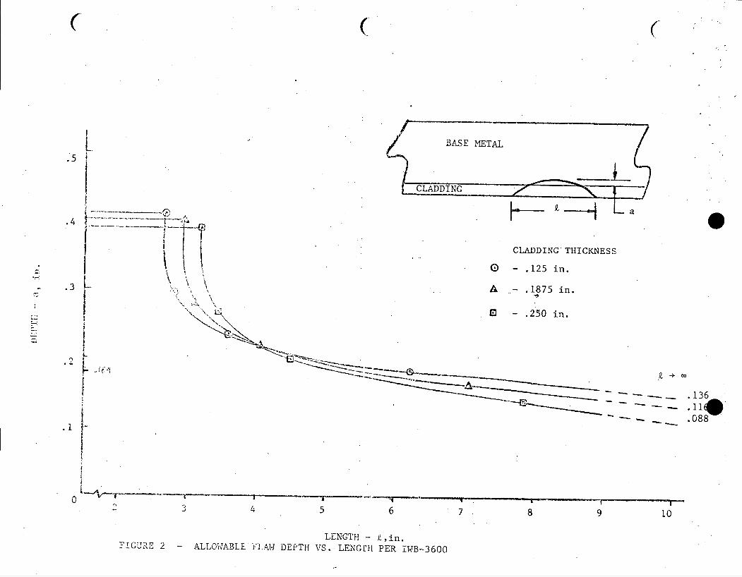
3. If flaws are found which fall above the curve in Figure 1, and below the
curve of Figure 2, the steam generators may be placed back in service with
the concurance of the proper authorities and regulatory agencies provided the
specified design cycles of the plant have not been exceeded.
4. Further flaw propagations can be justified on a case by case basis depending
on stresses at the location of the flaw and expected remaining cycles.
Wesinghouse Electric Corporation Tampa Oivision Nuclear Energy Systems Tampa. Florida. U. S. A.
NPT-81 Page 1 of 1
Issue 1
PURPOSE
The purpose of this specification is to give the proceedure for in-service inspec
tion of cladding flaws, evaluating the results, and determination if repairs
are required.
PART I BASE LINE INSPECTION
At the time flaws are detected, a base line inspection shall be made and clad
thickness in the surveillance region measured in accordance with NPT-61.
PART II DETERMINATION OF TOTAL FLAW DEPTH
Ultrasonically determine total flaw depth using Part II of NPT-61. Should the
flaw depth exceed j/8 inch, it must be further defined using Part III of NPT-61.
... L....&-

A.i WIT, M111. HR
AJ 1 MW, rti17-1
1 - fi 1H It1111 111
fl -4t ItI'lltmF1"H I
II 1- :4 Smi-m-ItRitMitL'U 44 Af ,
M MR _0_AR
----- --
lU- 1 M-11
S_ I- 1 1--t Itf 1111 -W- Af_1 4 1 tt
t ILIIt~- 4
+I t":AU 1M1, 41. j1
F- I 11F'T1 1 v T I t-i y i! r m i 1 1
H ii 10WR lt I ql
I It It
11I I t A1
IUE -Allowable I aw De7pt vs. Lengt peTWB-3L
lap. Ig 1444--rq
N!,
C
.5
.4
.3
CLADDING*THICKNESS
0 - .125 in.
. 10 in.
. -. 250 in.
---... 88136
-. .088
0
i
TGURE 2 - ALLOWABLELENGTH - L,in.
FLAW DEPTH VS. LENGPE[ PER !WB--3600
H-- i-H
O----q0

ATTACHMENT I
(SECTION 8 OF WESTINGHOUSE TAMPA DIVISION REPORT TD-MET-75-080)

SECTION 8
SERVICE EXPERIENCE
It has been established, by examination that the cladding flaws do not
extend into the carbon steel channel head base metal. It has further been
established that structurally the flaws are insignific'ant and are within
the specifications of Section XI. Finally, a nondestructive testing method
has expefimentally verified that flaws of a critical depth are determinable.
It remains to be shown that the cladding will satisfy its original purpose
of protecting the primary system coolant from excessive corrosion products
contamination.
Service experience with cladding which shows similar problems has shown no
adverse effect on performance. Over the past 20 years, cracking has occurred
in the corrosion resistant cladding of several nuclear steam supply system
vessels. For example, cracking has been found in roll-bonded clad, resistance
welded clad, arc welded clad, (Sequoia I Rotterdam KE2020 and JPDR). These.
examples are not a complete compilation of all cracking incidents but are
meant to be illustrative of the extent of the problem. Causes for the
cracking have been attributed to corrosion, hot cracking, improper welding,
metallurgical conditions, or various combinations of these. Extensive
metallurgical and structural investigations were made for each cracking
incident. In all cases, the cracking was confined to the corrosion
resistant cladding, i.e., in no cases did the cracks extend into the under
lying base metal. In some instances, attempts were made to propagate the
cracks into the base metal by fatigue. These were singularly unsuccessful.
In at least one example, the Yankee-Rowe pressurizer, the vessel containing
cracked cladding has seen extensive service -- over ten years. Periodic
inspections at refueling intervals have confirmed that crack growth has
not taken place. Furthermore, this plant has successfully operated even
though low alloy steel has been exposed to the primary coolant. The Yankee
Rowe inspection and service has been documented in periodic reports to the AEC.
In the case of the cracked cladding in the head of JPDR, a Japanese BWR, the
cracking in the weld deposited cladding was interdendritic near the surface

and transdendritic further inward. Base material, A302B, was exposed. After discovery of these cracks (,\,1966), unrepaired areas were deliberately
left for future observation. In 1968, a detailed metallographic examination
revealed only minor pitting about 0.004" in the exposed base metal at the tip
of some of the cracks. The environment was fairly aggressive since 35 ppm
oxygen was present in the steam phase. (I)
This service experience indicates that the flaws in the cladding are not detrimental, and lend credability to the stability of the weld deposit.
The probability of "grain dropping", i.e., granular particle falling from the
clad matrix cannot be ignored but is believed to be very low. "Grain dropping" would occur only if exposure to the corrodant continued. Since the primary system operates with an extremely low oxygen and chloride content deterioration
of the cladding by this method is not anticipated.
The following corrosion data indicate that should cracks propagate to base metal, the corrosion rates in service are acceptable under all conditions.
Hot A. Environment #1 Startup Operating Shutdown Shutd
Temperature, 0F 100 to 630 630 630 180
Velocity, fps 14 14 14 14
)wn
Chemistry:
Boron (as H3BO3 ), ppm
Lithium (as LiOH), ppm
Chloride, ppm
Fluoride, ppm
Oxygen, ppm
Hydrazine, ppm
Hydrogen, cc/kg
Exposure Time, day
Material
Corrosion Rate
0 1200-0
1 to 2 0.5 to 2
1.0 to <0.15 <0.15
<0.15 <0.15
7 to <0.1 <0.1
21 to <0.1 <0.1
0 to.30 30
15 365
SA-556-C2 Carbon Steel
105 mg/dm2 /429 days
(0.6 mils/429 day)
2000
1 to 2
<0.15
<0.15
<0.1
30 to 0
28
2000
1.5 to
<0.15
<0.15
2.0
Reference: Westinghouse corrosion data obtained from testing in
simulated reactor coolant conditions.
8-2

B. Environment #2 0
Temperature, F
Velocity, fps
Chemistry:
Boron (as H3B03), ppm
Lithium as (LiOH), ppm
Chloride, ppm
Fluoride, ppm
Oxygen, ppm
Hydrazine, ppm
Exposure Time, day
Material
Corrosion Rake vs6 Temp., mg/dm -mo/ K
Aerated Solutions Coupled to S/S
-o
70 to 140
Stirred
2500
None
<0.15
<0.15
7 to 3
None
120
SA-3028 Carbon Steel
-4.6 x 10⁶ + 1.6 x 10⁴
1
Deaerated Solution Coupled to S/S
70 to 140
Stirred
2500
None
<0.15
<0.15
<0.1
7 to
120
<0.1
-4.6 x 10⁴ + 1.5 x 10 2
1
Reference: WCAP-7099, "Absorption of Corrosion Hydrogen by
at 700 to 5000 F," December 1967.
C. Environment #3
Temperature, OF
Velocity, fps
Chemistry:
Boron (as H3BO3), ppm
Lithium (as LiOH), ppm
Chloride, ppm
Fluoride, ppm
Oxygen, ppm
Hydrogen, cc/kg
Exposure Time, day
Material
Corrosion Rate
Reference:
A3028 Steel
650
Semistatic
1100
None
Not given
Not given
<0.1
100
28
Carbon Steel Plate
105 mg/din2 (0.6 mils/yr)
TID-10028 Technical Progress Report, "PWR Program for Period October 7, 1954 to November 18, 1954, and WCAP-2855, "Evaluation of Yankee Vessel Cladding Penetrations," October 1965.
8-3

The corrosion data from Environment #1 should be directly applicable to the
steam generator carbon steel corrosion since the test conditions represent
a fuel cycle. The corrosion at low temperatures only are defined in
Environment #2 while the corrosion at operating temperatures is defined in
Environment #3.
Hydrogen release by corrosion reactions has been shown not to have an
embrittlement effect on A302 steel and it is believed that no effect will
be seen here. (2)
8-4

REFERENCES
1. T. Kondo, H. Nakajima, and R. Nagasaki, "Metallographic Investigation on the Cladding Failure in the Pressure Vessel of a BWR," Nuclear Engineering and Design, Vol. 16,'No. 3, July 1971, pp. 205-222.
2. Westinghouse Report WCAP-7099, "Absorption of Corrosion Hydrogen by
A302B Steel at 700 to 500°F".
8-5

0 0
ATTACHMENT II
(WESTINGHOUSE TAMPA DIVISION REPORT TD-MET-77-110)