Embed Size (px)
Citation preview
GUIDANCE FOR THE PREPARATION OF A METERING PLAN &
A GROUNDWATER ELEVATION MONITORING PLAN FOR
WATER WITHDRAWALS, CONSUMPTIVE USES, AND DIVERSIONS
Policy 2020 – 00X
[DATE]
GUIDANCE FOR THE PREPARATION OF A METERING PLAN &
A GROUNDWATER ELEVATION MONITORING PLAN FOR
WATER WITHDRAWALS, CONSUMPTIVE USES, AND DIVERSIONS
[DATE]
This document provides guidance for preparation of the metering plan required as part of a
project application under 18 CFR § 806.14(a)(6) and (c)(5), CFR § 806.22(e)(4), CFR
§ 806.22(f)(4) that adheres to the standards in 18 CFR § 806.30 for the methodology for
monitoring water withdrawals and consumptive uses. It also provides guidance for the
groundwater elevation monitoring plan (GWEMP) required for groundwater withdrawal
applications under 18 CFR § 806.14(b)(2)(iv) that adheres to the standards in 18 CFR § 806.30.
Specifically, this guidance applies to projects with surface water sources or groundwater sources
for new, renewal, major modification, minor modification (as applicable), consumptive use, and
diversion applications.
In general for all projects, these plans should reflect the most up-to-date information for an
entire facility’s metering and groundwater elevation monitoring needs and requirements.
Specifically, the plans should concisely describe a facility’s source(s) of water, consumptive
use(s) of water (except Approval by Rule hydrocarbon projects), diversion of water (import
and/or export), existing or proposed monitoring equipment, infrastructure, and measurement or
monitoring methodologies that are or will be used.
For a proposed renewal of an existing project, the project sponsor’s plan should reflect the
facility’s as-built condition for monitoring methods. At the time of application for renewal, if a
plan does not accurately describe the as-built condition, an updated plan will be required to be
submitted that accurately describes the as-built condition. The project sponsor should use this
guidance document to update the plan. Plans that have been approved by the Commission and
accurately describe the as-built condition do not have to be revised per this guidance document.
For a proposed major or minor modification to an existing project, the project sponsor
should include a description of the as-built condition and, if appropriate, update(s) to the existing
plan(s) clearly describing and illustrating the changes as a result of the proposed modification.
For a project seeking an approval for consumptive use of water related to unconventional
natural gas and other hydrocarbon development through the administrative Approval by Rule in
CFR § 806.22(f)(4), the metering plan should conform to the prescribed Consumptive Use
Metering Plan For Approval By Rule 18 CFR § 806.22(f) available at the Commission’s website
(https://www.srbc.net/). For consumptive use projects seeking approval through the Approval by
Rule at 18 CFR § 806.22(e), the metering plan should follow the guidelines below.
Guidance for Preparation of Metering & - 2 - [DATE]
Groundwater Elevation Monitoring Plans
I. Metering Plan – Suggested Outline for All Projects
Per 18 CFR §§ 806.30 (a)(1-7), a project sponsor is required to:
Measure and record, on a daily basis, the quantity of all withdrawals, using meters or
other methods approved by the Commission.
Certify, at the time of installation and no less frequently than once every 5 years, the
accuracy of all measuring devices and methods to within 5 percent of actual flow.
Maintain metering to provide a continuous, accurate record of the withdrawal or
consumptive use.
Measure groundwater levels in all approved production and other wells, as specified.
Measure groundwater levels at additional monitoring locations, as specified.
Measure water levels in surface storage facilities, as specified.
Measure streamflows, passby flows or conservation releases, as specified.
Perform other monitoring for impacts to water quantity, water quality, and aquatic
biological communities, as specified.
The metering plan should concisely describe the equipment and methodologies that will be
used to satisfy these requirements and should include, but may not be limited to, the following:
A. General Description of Project Facilities1
1. Describe the operations that are conducted at the facility.
2. Describe how water is used at the facility.
3. Identify all withdrawal sources and consumptive uses at the facility.
4. If applicable, identify any diversions of water into and/or out of the basin by the
facility.
5. Provide a water flow diagram illustrating the processes that use the water
withdrawn from the sources or diverted into and/or out of the basin, all water
flow pathways, and the locations in the flow pathway of all meters used to
account for the withdrawals, consumptive uses, and diversions.
6. Provide a topographic map or aerial photograph depicting the locations of all
withdrawal sources, water storage or treatment units, discharge points, and
meters used to account for the withdrawals, consumptive uses, and diversions.
This map may be combined with the flow diagram described in item 5 above, if
appropriate.
B. Description of Meters, Associated Equipment and Measurement Procedures
1. Indicate the make, model, size, serial number, flow range, and accuracy of all
proposed or existing flow meters or measurement equipment. It may be helpful
1 Facility, as defined in 18 CFR § 806.3, includes, but is not limited to, the site where the water from the source will
be used and where any appurtenances necessary for the withdrawal, control, collection, storage, treatment,
transmission, sale, or exchange of water are or will be located.
Guidance for Preparation of Metering & - 3 - [DATE]
Groundwater Elevation Monitoring Plans
to summarize these details in table format. Please include the manufacturer’s
specification information for the meter. Please do not include manufacturer’s
operation manuals.
2. Indicate the type of meter displays or transmitters, the display capabilities, and
the number of digits capable of recording and displaying. Meter displays and
transmitters should be capable of displaying both a maximum instantaneous
flow rate and a totalized flow quantity, recordable to at least 8 digits to prevent
frequent rollover (see example photographs in Appendix B).
3. Indicate where the meters and meter displays are or will be located and how
Commission staff will have access during routine compliance inspections. The
proposed or existing meters should be installed so that they cannot be easily
bypassed, zeroed, or reset.
4. Describe the equipment and methods (e.g., valve controls, variable frequency
drives, pump capacity) that will be used to adhere to the proposed or approved
individual and combined/total system withdrawal limits and maximum
instantaneous withdrawal rates.
a) For projects that use the pump capacity as the flow-limiting device,
pump curves should be provided to demonstrate that the pump will not
exceed the proposed or approved withdrawal rates.
5. Provide photographs of all installed meters showing the meter display, including
the piping before and after the meter to document that the meter has been
installed in accordance with the appropriate straight-run requirements, and
close-up detail (i.e., make, model, and serial number).
a) For meters that have not been installed, provide a proposed schedule for
installing the metering equipment and initiating flow monitoring.
b) Following installation of the meter(s), submit date(s) of meter(s)
installation and photographs of the installed equipment.
6. If applicable, describe how the consumptive use of water at the facility will be
measured or calculated.
a) Please note that the Commission prefers the simplest methods be
implemented to measure or calculate consumptive use, which is
generally the sum of the sources less the discharge (i.e., CU = Total of
Sources In – Discharge). It may be appropriate to calculate certain
consumptive uses in place of direct measurement with meters,
particularly when metering is not feasible. Include an equation that
clearly describes the components and assumptions that are used in the
calculation.
b) Evaporative losses (e.g., from storage ponds or open-top storage units)
may need to be considered and included in the calculation. A sample
calculation for evaporative losses is provided in Commission Form
SRBC #74 (https://www.srbc.net/regulatory/application-process/).
Guidance for Preparation of Metering & - 4 - [DATE]
Groundwater Elevation Monitoring Plans
Briefly describe how the surface area used in the calculation was
derived.
7. It may be appropriate to use equipment other than meters, procedures, or
calculations to measure certain withdrawals or consumptive uses, particularly
when metering is not feasible. All assumptions used in calculations must be
provided and clearly explained.
C. Monitoring Procedures and Record Keeping
1. Describe the procedures recording daily flow and consumptive use data from
the measurement equipment during daily operations.
2. Describe the methods for maintaining an accurate record of daily water
withdrawals, consumptive use, and diversions (e.g., handwritten daily logs,
electronic spreadsheets) Please note that all withdrawal data collected by the
project sponsor and submitted to the Commission must be maintained by the
project sponsor for the duration of the approvals and subsequent renewals as
required by the Commission-issued docket or approval.
D. Calibration/Certification of Metering Equipment
Per 18 CFR § 806.30(a)(2), a project sponsor is required to maintain flow
measuring devices accurate to within 5 percent of actual flow to provide an accurate
record of withdrawals, consumptive use, and diversions. For existing meters, current
meter certifications should be included in the metering plan. For new meters, the
manufacturer’s specification sheet should be provided. Once the meter has been
installed, the manufacturer’s calibration report or accuracy certification sheet must be
provided to the Commission.
Project sponsors are required to certify, at the time of installation and no less
frequently than once every five years, the accuracy of all flow measuring devices and
methods, unless otherwise specified by the Commission. The Commission does not
require specific methods for certifying the accuracy of flow measuring devices;
however, it is expected that the devices be maintained to the standards of their
respective manufacturers. Common methods for certifying meter accuracy are
provided as options in Appendix D.
Guidance for Preparation of Metering & - 5 - [DATE]
Groundwater Elevation Monitoring Plans
II. Groundwater Elevation Monitoring Plan - Suggested Outline
Per 18 CFR §§ 806.30(a)(4) and (a)(5) a project sponsor is required to measure and record
groundwater levels in all approved production wells and other wells and monitoring locations, as
specified by the Commission. The GWEMP should concisely describe the equipment and
methodologies that will be used to satisfy these requirements and should include, but may not be
limited to, the following:
A. Indicate the location, type2, make, model, serial number, and accuracy for all
proposed or existing manual and/or automated groundwater elevation monitoring
equipment. If data loggers are installed to measure and record water level data,
please indicate the depth at which the data logger is set and its position relative to the
pump intake. It may be helpful to summarize these details in table format. Please
provide the manufacturer’s specification sheet and calibration reports for existing (if
available) and new water level monitoring equipment. Please do not include
manufacturer’s operation manuals.
B. Indicate the frequency at which water level data will be collected. The Commission
prefers that the lowest daily water level data be reported. If measuring and reporting
the lowest daily water level is not practical or feasible, water level measurements
should be collected at the same time each day. Please note that staff may consider
alternative data collection frequencies if collection of daily water level data is not
feasible for your project. Please contact Commission staff to discuss possible
alternative data collection frequencies, if needed.
C. Provide a description of the reference points used to calculate groundwater elevations
from water levels measured at each production well and/or other monitoring
locations. Groundwater elevations should be reported in feet above mean sea level.
Reference point elevations can be obtained using standard surveying techniques,
handheld global positioning system unit, LiDAR data, or topographic maps. It may
be useful to include the reference point elevations in the table with the information
requested above in item A.
D. Describe the procedures for reading and recording water level measurements from all
groundwater monitoring locations.
E. Describe the methods for maintaining an accurate record of groundwater elevation
data. All groundwater elevation data collected by the project sponsor and submitted
to the Commission must be maintained by the project sponsor for the duration of any
approvals and subsequent renewals as required in the Commission-issued docket or
approval.
F. Provide photographs of any existing water level monitoring equipment or
photographs showing installed equipment, if applicable.
2 “Type” may include water level meters, airlines, data loggers, etc. If non-vented data loggers are utilized, please
indicate how water levels will be corrected for barometric pressure and indicate the location where barometric data
loggers will be installed.
Guidance for Preparation of Metering & - 6 - [DATE]
Groundwater Elevation Monitoring Plans
1. For equipment that has not been installed, provide a proposed schedule for
installing the equipment and initiating water level monitoring. Following
installation of the equipment, the GWEMP should be updated, as needed, to
include the information requested in this section and photographs of the
installed equipment.
G. The project sponsor is responsible for maintaining and verifying the proper function
of all groundwater level monitoring equipment. The plan should provide for periodic
back-up measurements from each groundwater monitoring location to check the
calibration of the primary measuring equipment and procedures that will be
implemented in the event of failure of the primary measuring equipment. The
Commission recommends that manual backup measurements be collected at least
once per quarter to verify the accuracy and proper function of any water level
monitoring equipment installed in the well.
- 7 -
APPENDIX A
GENERALIZED METERING PLAN TEMPLATE
The following provides a generalized template for use by the project sponsor in
developing a facility’s metering plan. The project sponsor may need to provide more or less
detail, as appropriate, to adequately describe the project facilities and water uses.
TITLE OF PLAN
Project Sponsor
Facility Name
Municipality, County, State
Date
General Description of Project Facilities
Insert narrative description including, but not limited to:
Facility location;
Water source(s);
Water use(s);
Water flow path, including pump usage, location, and meter location(s);
Consumptive use(s) of the water;
Discharge location;
Water flow path schematic (Attachment 1);
Aerial photograph that depicts locations of the water source(s), flow meter(s), meter
readout(s), storage unit(s), and discharge location(s) (Attachment 2).
Meter Information
Insert brief narrative description regarding flow meter location(s) and accessibility. Use
Table 1 to provide meter specifications. Include photographs of each meter, and the most recent
certifications of meter accuracy as Attachments 3 & 4, respectively.
Insert brief narrative description regarding control of each source(s) flow rate. Include
any appropriate information regarding valves and/or locks as related to the approved maximum
instantaneous withdrawal rates. Provide pump curves as Attachment 5, if needed to demonstrate
compliance with the maximum instantaneous withdrawal rate.
- 8 -
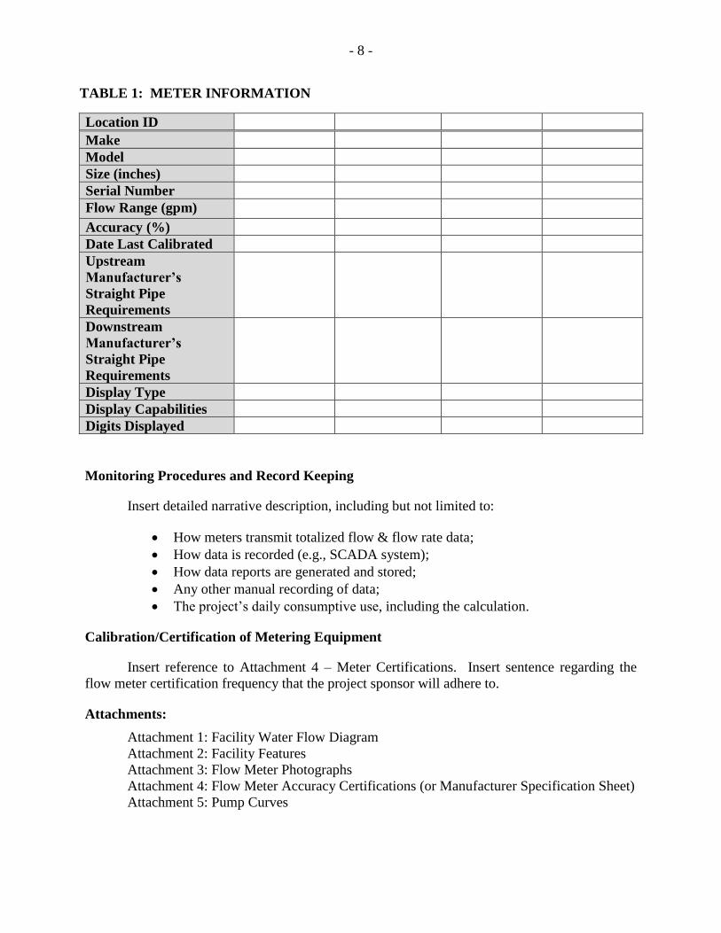
TABLE 1: METER INFORMATION
Location ID
Make
Model
Size (inches)
Serial Number
Flow Range (gpm)
Accuracy (%)
Date Last Calibrated
Upstream
Manufacturer’s
Straight Pipe
Requirements
Downstream
Manufacturer’s
Straight Pipe
Requirements
Display Type
Display Capabilities
Digits Displayed
Monitoring Procedures and Record Keeping
Insert detailed narrative description, including but not limited to:
How meters transmit totalized flow & flow rate data;
How data is recorded (e.g., SCADA system);
How data reports are generated and stored;
Any other manual recording of data;
The project’s daily consumptive use, including the calculation.
Calibration/Certification of Metering Equipment
Insert reference to Attachment 4 – Meter Certifications. Insert sentence regarding the
flow meter certification frequency that the project sponsor will adhere to.
Attachments:
Attachment 1: Facility Water Flow Diagram
Attachment 2: Facility Features
Attachment 3: Flow Meter Photographs
Attachment 4: Flow Meter Accuracy Certifications (or Manufacturer Specification Sheet)
Attachment 5: Pump Curves
- 9 -
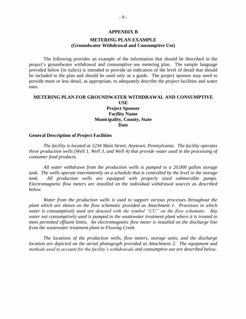
APPENDIX B
METERING PLAN EXAMPLE
(Groundwater Withdrawal and Consumptive Use)
The following provides an example of the information that should be described in the
project’s groundwater withdrawal and consumptive use metering plan. The sample language
provided below (in italics) is intended to provide an indication of the level of detail that should
be included in the plan and should be used only as a guide. The project sponsor may need to
provide more or less detail, as appropriate, to adequately describe the project facilities and water
uses.
METERING PLAN FOR GROUNDWATER WITHDRAWAL AND CONSUMPTIVE
USE
Project Sponsor
Facility Name
Municipality, County, State
Date
General Description of Project Facilities
The facility is located at 1234 Main Street, Anytown, Pennsylvania. The facility operates
three production wells (Well 1, Well 3, and Well 4) that provide water used in the processing of
consumer food products.
All water withdrawn from the production wells is pumped to a 20,000 gallon storage
tank. The wells operate intermittently on a schedule that is controlled by the level in the storage
tank. All production wells are equipped with properly sized submersible pumps.
Electromagnetic flow meters are installed on the individual withdrawal sources as described
below.
Water from the production wells is used to support various processes throughout the
plant which are shown on the flow schematic provided as Attachment 1. Processes in which
water is consumptively used are denoted with the symbol “CU” on the flow schematic. Any
water not consumptively used is pumped to the wastewater treatment plant where it is treated to
meet permitted effluent limits. An electromagnetic flow meter is installed on the discharge line
from the wastewater treatment plant to Flowing Creek.
The locations of the production wells, flow meters, storage units, and the discharge
location are depicted on the aerial photograph provided as Attachment 2. The equipment and
methods used to account for the facility’s withdrawals and consumptive use are described below.
- 10 -
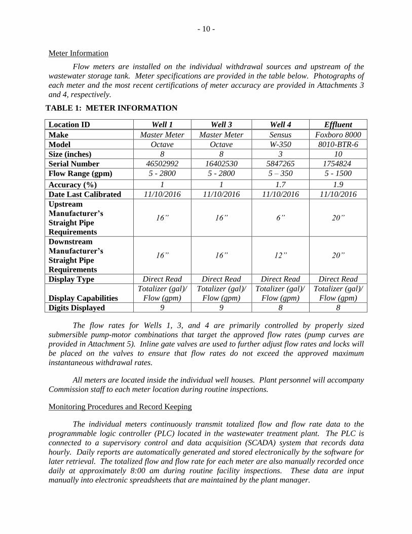
Meter Information
Flow meters are installed on the individual withdrawal sources and upstream of the
wastewater storage tank. Meter specifications are provided in the table below. Photographs of
each meter and the most recent certifications of meter accuracy are provided in Attachments 3
and 4, respectively.
TABLE 1: METER INFORMATION
Location ID Well 1 Well 3 Well 4 Effluent
Make Master Meter Master Meter Sensus Foxboro 8000
Model Octave Octave W-350 8010-BTR-6
Size (inches) 8 8 3 10
Serial Number 46502992 16402530 5847265 1754824
Flow Range (gpm) 5 - 2800 5 - 2800 5 – 350 5 - 1500
Accuracy (%) 1 1 1.7 1.9
Date Last Calibrated 11/10/2016 11/10/2016 11/10/2016 11/10/2016
Upstream
Manufacturer’s
Straight Pipe
Requirements
16” 16” 6” 20”
Downstream
Manufacturer’s
Straight Pipe
Requirements
16” 16” 12” 20”
Display Type Direct Read Direct Read Direct Read Direct Read
Display Capabilities
Totalizer (gal)/
Flow (gpm)
Totalizer (gal)/
Flow (gpm)
Totalizer (gal)/
Flow (gpm)
Totalizer (gal)/
Flow (gpm)
Digits Displayed 9 9 8 8
The flow rates for Wells 1, 3, and 4 are primarily controlled by properly sized
submersible pump-motor combinations that target the approved flow rates (pump curves are
provided in Attachment 5). Inline gate valves are used to further adjust flow rates and locks will
be placed on the valves to ensure that flow rates do not exceed the approved maximum
instantaneous withdrawal rates.
All meters are located inside the individual well houses. Plant personnel will accompany
Commission staff to each meter location during routine inspections.
Monitoring Procedures and Record Keeping
The individual meters continuously transmit totalized flow and flow rate data to the
programmable logic controller (PLC) located in the wastewater treatment plant. The PLC is
connected to a supervisory control and data acquisition (SCADA) system that records data
hourly. Daily reports are automatically generated and stored electronically by the software for
later retrieval. The totalized flow and flow rate for each meter are also manually recorded once
daily at approximately 8:00 am during routine facility inspections. These data are input
manually into electronic spreadsheets that are maintained by the plant manager.
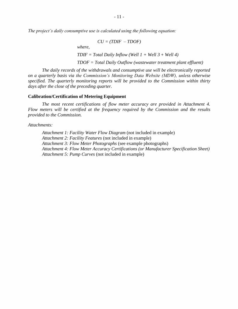
- 11 -
The project’s daily consumptive use is calculated using the following equation:
CU = (TDIF – TDOF)
where,
TDIF = Total Daily Inflow (Well 1 + Well 3 + Well 4)
TDOF = Total Daily Outflow (wastewater treatment plant effluent)
The daily records of the withdrawals and consumptive use will be electronically reported
on a quarterly basis via the Commission’s Monitoring Data Website (MDW), unless otherwise
specified. The quarterly monitoring reports will be provided to the Commission within thirty
days after the close of the preceding quarter.
Calibration/Certification of Metering Equipment
The most recent certifications of flow meter accuracy are provided in Attachment 4.
Flow meters will be certified at the frequency required by the Commission and the results
provided to the Commission.
Attachments:
Attachment 1: Facility Water Flow Diagram (not included in example)
Attachment 2: Facility Features (not included in example)
Attachment 3: Flow Meter Photographs (see example photographs)
Attachment 4: Flow Meter Accuracy Certifications (or Manufacturer Specification Sheet)
Attachment 5: Pump Curves (not included in example)
- 12 -
Attachment 3: Meter Photographs
Well 1: Meter Installed in Accordance with Straight-Run Recommendations
[Insert photo of installed meter here]
- 13 -
Well 1: Close-up of Display
[Insert photo of close-up view of meter display here]
- 14 -
Attachment 4: Flow Meter Manufacturer Specification Sheet
[Insert flow meter manufacturer spec sheet here]
- 15 -
APPENDIX C
GROUNDWATER ELEVATION MONITORING PLAN EXAMPLE
The following provides an example of the information that should be described in the
project’s groundwater elevation monitoring plan (GWEMP). The sample language provided
below (in italics) is intended to provide an indication of the level of detail that should be
included in the plan and should be used only as a guide. The project sponsor may need to
provide more or less detail, as appropriate, to adequately describe the equipment and methods
implemented to measure, record, and report water level data for the facility’s approved
groundwater sources, and other wells and monitoring locations, as specified by the Commission.
GROUNDWATER ELEVATION MONITORING PLAN
Project Sponsor
Facility Name
Municipality, County, State
Date
The facility operates three groundwater wells (Well 1, Well 3, and Well 4), which are the
sources for all water used at the plant. Groundwater levels will be measured in each production
well using vented data loggers, which are described in the following table.
GROUNDWATER MONITORING EQUIPMENT
Source
Reference
Elevation
Location
Reference
Elevation
(ft AMSL)
Data Logger Information
Make / Model
Serial
Number
Accuracy
(%)
Well 1
Top of
Casing 1180.36
In-Situ Level
Troll 500 455154 0.1
Well 3
Top of
Casing 1050.27
HOBO Water
Level Logger 465758 0.1
Well 4
Top of
Casing 1129.05
Solinist
Levellogger
Edge 359875 0.05
Each data logger will be programmed to record depth to water levels on an hourly basis.
The plant manager will manually download the water level data from the data loggers monthly
and will upload the data to an electronic spreadsheet. Groundwater levels for the production
wells will be converted to elevations by subtracting the depth to water measurements from the
top of casing elevations at each wellhead, which were obtained by professional survey. The
lowest daily groundwater elevations will be reported quarterly to the Commission.
To ensure accurate operation of the data loggers, the water level measurements recorded
by the data loggers will be manually verified every quarter using a water level meter. If
discrepancies are noted, the data logger will be recalibrated or replaced with a new data logger.
Manual water level measurements will be collected as needed until the data logger is replaced.
The Commission will be informed of any changes in equipment and the GWEMP will be updated
to provide the new make, model, serial number, and photographs of installed equipment.

- 16 -
Attachment 1: Water Level Monitoring Equipment Photographs (see attached example)
Attachment 2: Water Level Monitoring Equipment Accuracy Certifications (see attached
example)
- 17 -
Attachment 1: Water Level Monitoring Equipment Photographs
[Insert water level monitoring equipment photo(s) here]
- 18 -
Attachment 2: Water Level Monitoring Equipment Accuracy Certification
[Insert water level monitoring equipment accuracy certification here]
- 19 -
APPENDIX D
METER ACCURACY CERTIFICATION METHODS EXAMPLE
Project sponsors are required to certify, at the time of installation and no less frequently
than once every five years, the accuracy of all flow measuring devices and methods, unless
otherwise specified by the Commission. The Commission does not require specific methods for
certifying the accuracy of flow measuring devices; however, it is expected that the devices be
maintained to the standards of their respective manufacturers. Questions regarding specific
methods for the certification of meter accuracy that may be acceptable to the Commission should
be directed to Commission staff. However, several common methods are described below.
1. The existing flow meter is replaced with a meter that has been previously
calibrated to manufacturer specifications and certified by the manufacturer or an
independent contractor.
2. The existing meter is removed and shipped to the manufacturer or an
independent contractor for calibration and certification at their facility.
3. Generally, a qualified independent contractor performs calibration and
certification of the existing meter on-site. Calibration and certification by a
qualified employee of the project may be accepted as appropriate. On-site
meter calibration is often completed in one of the following ways:
a) A known quantity of water is pumped through the metering device and
compared with the totalizer reading of the known quantity of water.
b) A previously calibrated and certified meter is installed on an influent or
effluent line common to the existing meter. The pump is operated for a
fixed amount of time and the totalizer readings of the two meters (the
existing meter being tested and the independent contractor’s certified
meter) are compared for accuracy.
c) A previously calibrated ultrasonic flow measuring instrument is installed
(clamped) over the pipe in the vicinity of the existing metering device.
The pump is operated for a fixed amount of time and the totalizer readings
of the two meters (the existing meter being tested and the independent
contractor’s certified meter) are compared for accuracy.
465451.1