Embed Size (px)
Citation preview
Date of Release: June 1, 2021Date of Hearing: July 22, 2021
Appendix A
Proposed Regulation Order, OBD II Regulation
Title 13, California Code of Regulations, Section 1968.2, Malfunction and Diagnostic
System Requirements--2004 and Subsequent Model-Year Passenger Cars, Light-Duty Trucks,
and Medium-Duty Vehicles and Engines
Proposed Revisions to the On-Board Diagnostic System Requirements and Associated Enforcement Provisions for Passenger Cars, Light-Duty Trucks, Medium-Duty
Vehicles and Engines, and Heavy-Duty Engines

[This page intentionally left blank]
1
Appendix A
Proposed Regulation Order
Amend section 1968.2, title 13, California Code of Regulations, to read as follows:
(Note: The proposed amendments are shown in underline to indicate additions and strikeout to indicate deletions from the existing regulatory text. Various portions of the regulations that are not modified by the proposed amendments are omitted from the text shown and indicated with “* * * *”.)
§1968.2. Malfunction and Diagnostic System Requirements--2004 and Subsequent Model-Year Passenger Cars, Light-Duty Trucks, and Medium-Duty Vehicles and Engines
* * * *(c) Definitions.
* * * *“Calculated load value” refers to an indication of the percent engine capacity
that is being used and is defined in SAE International (SAE) J1979 "E/E Diagnostic Test Modes", (SAE J1979), incorporated by reference (section (g)(1.4)1), or SAE J1979-2 “E/E Diagnostic Test Modes - OBDonUDS”, incorporated by reference (section (g)(1.4.2)). For diesel applications, in lieu of the definitions in SAE J1979 and SAE J1979-2, the calculated load value may alternatively be determined by the ratio of current engine torque to maximum engine torque at current engine speed as defined by suspect parameter number (SPN) 92 of SAE J1939 “Serial Control and Communications Heavy Duty Vehicle Network – Top Level Document” (SAE J1939), incorporated by reference.
* * * *“Charge sustaining target SOC value” means the nominal target SOC that the
control system is designed to maintain, on average, when operating as a conventional hybrid vehicle after depletion of any grid energy in the battery.
“Cold start emission reduction strategy (CSERS) cold start criteria” is defined as a set of criteria that meet all the following conditions in a single driving cycle:
(1) at least 6 hours of engine-off time before the initial combustion engine start for non-hybrid vehicles, or the continuous time the vehicle is not in a state of “propulsion system active” during the period immediately preceding the start of “propulsion system active” is at least 6 hours for hybrid vehicles,
(2) the ambient temperature is greater than or equal to 19.4 degrees Fahrenheit (or -7 degrees Celsius), and
1 Unless otherwise noted, all section references refer to section 1968.2 of title 13, CCR.

2
(3) the engine coolant temperature is less than or equal to 27 degrees Fahrenheit (or 15 degrees Celsius) higher than the ambient temperature.
* * * *“Federal Test Procedure (FTP) test” refers to an exhaust emission test
conducted according to the test procedures incorporated by reference in title 13, CCR section 1961(d) that is used to determine compliance with the FTP standard to which a vehicle is certified.
“FTP cycle”. For passenger vehicles, light-duty trucks, and medium-duty vehicles certified on a chassis dynamometer, FTP cycle refers to the driving schedule in Code of Federal Regulations (CFR) 40, Appendix 1, Part 86, section (a) entitled, “EPA Urban Dynamometer Driving Schedule for Light-Duty Vehicles and Light-Duty Trucks.” (i.e., the FTP-72 cycle or LA-4 cycle). For medium-duty engines certified on an engine dynamometer, FTP cycle refers to the engine dynamometer schedule in CFR 40, Appendix 1, Part 86, section (f)(1), entitled, “EPA Engine Dynamometer Schedule for Heavy-Duty Otto-Cycle Engines,” or section (f)(2), entitled, “EPA Engine Dynamometer Schedule for Heavy-Duty Diesel Engines.”
* * * *“Low Emission Vehicle III application” refers to a vehicle or engine certified in
California to the exhaust emission standards defined in title 13, CCR section 1961.2,. Additionally, vehicles certified to Federal emission standards (bins) in California but categorized in a Low Emission Vehicle III vehicle emission category for purposes of calculating NMOG+NOx fleet average in accordance with the certification requirements and test procedures incorporated by reference in title 13, CCR section 1961.2 (d) are subject to all monitoring requirements applicable to Low Emission Vehicle III applications but shall use the Federal tailpipe emission standard (i.e., the Federal bin) for purposes of determining the malfunction thresholds in sections (e) and (f).
* * * *(d) General Requirements.
Section (d) sets forth the general requirements of the OBD II system. Specific performance requirements for components and systems that shall be monitored are set forth in sections (e) and (f) below.
(1) The OBD II System.* * * *
(1.4) Computer-coded engine operating parameters may not be changeable without the use of specialized tools and procedures (e.g., soldered or potted computer components or sealed (or soldered) computer enclosures). Subject to Executive Officer approval, manufacturers may exempt from this requirement those product lines that are unlikely to require protection. Criteria to be evaluated in making an exemption include current availability of performance chips, high performance capability of the vehicle, and sales volume.
* * * *

3
(2) MIL and Fault Code Requirements.(2.1) MIL Specifications.
* * * *(2.1.3) At the manufacturer's option, the MIL may be used to indicate readiness
status in a standardized format (see section (g)(4.1.31)(H) or (g)(4.1.2)(F)) in the key on, engine off position.
* * * *(2.2) MIL Illumination and Fault Code Storage Protocol.
* * * *(2.2.7) Storing and Erasing “Freeze Frame” Conditions. A manufacturer shall
store and erase “freeze frame” conditions (as defined in section (g)(4.3)) present at the time a malfunction is detected.
(A) For vehicles using SAE J1979, aA manufacturer shall store and erase freeze frame conditions in conjunction with storage and erasure of either pending or confirmed fault codes as required elsewhere in section (d)(2.2). If freeze frame conditions are currently stored for a fault code, the freeze frame conditions may not be replaced with freeze frame conditions for another fault code except as allowed for gasoline and diesel misfire and fuel system monitors under sections (e)(3.4.53.4.4), (e)(6.4.4), (f)(3.4.2)(B), and (f)(4.4.2)(D).
(B) For vehicles using SAE J1979-2, the OBD II system shall store freeze frame conditions on two frames of data (referred to as the “first frame” and “second frame”) for a given fault code in conjunction with the storage of a pending fault code. After storage of the pending fault code and freeze frame conditions, if the malfunction is again detected within the same driving cycle, the OBD II system may replace the stored freeze frame conditions on the second frame with freeze frame conditions for the redetected malfunction anytime the malfunction is redetected.(i) If the pending fault code is erased in the next driving cycle in which
monitoring occurs and a malfunction is not detected (as described in section (d)(2.2.2)), the OBD II system shall erase the corresponding freeze frame conditions on the first and second frames for the fault code.
(ii) If the pending fault code matures to a confirmed fault code (as described in section (d)(2.2.2)), the OBD II system shall retain the freeze frame conditions stored with the pending fault code on the first frame and replace the stored freeze frame conditions on the second frame with freeze frame conditions of the confirmed fault code. After storage of the confirmed fault code and freeze frame conditions, if the malfunction is again detected within the same driving cycle, the OBD II system may replace the stored freeze frame conditions on the second frame with freeze frame conditions for the redetected malfunction anytime the malfunction is redetected.
(iii) If the malfunction is detected during a driving cycle after the driving cycle in which the confirmed fault code was first stored, the OBD II system shall replace the stored freeze frame conditions on the second
4
frame with freeze frame conditions of the redetected malfunction. If the malfunction is again detected within the same driving cycle, the OBD II system may replace the stored freeze frame conditions on the second frame with freeze frame conditions for the redetected malfunction anytime the malfunction is redetected.
(iv) The OBD II system shall erase the freeze frame conditions on the first and second frames in conjunction with the erasure of the confirmed fault code as described under section (d)(2.4).
(v) Except as provided below in section (d)(2.2.7)(B)(v)a., if a fault code is stored when the maximum number of frames of freeze frame conditions is already stored in the diagnostic or emission critical powertrain control unit, the OBD II system may not replace any currently stored freeze frame conditions in the control unit with freeze frame conditions for the newly stored fault code.a. For 2023 through 2026 model year vehicles, if a misfire or fuel
system fault code is stored when the maximum number of frames of freeze frame conditions is already stored in the diagnostic or emission critical powertrain control unit, the OBD II system may replace any of the currently stored freeze frame conditions for a fault code in the control unit with freeze frame conditions for the newly stored fault code as allowed for gasoline and diesel misfire and fuel system monitors under sections (e)(3.4.4), (e)(6.4.4), (f)(3.4.2)(B), and (f)(4.4.2)(D).
* * * *(3) Monitoring Conditions.
Section (d)(3) sets forth the general monitoring requirements while sections (e) and (f) set forth the specific monitoring requirements as well as identify which of the following general monitoring requirements in section (d)(3) are applicable for each monitored component or system identified in sections (e) and (f).
* * * *(3.2) As specifically provided for in sections (e) and (f), manufacturers shall define
monitoring conditions in accordance with the criteria in sections (d)(3.2.1) through (3.2.3). The requirements of section (d)(3.2) shall be phased in as follows: 30 percent of all 2005 model year vehicles, 60 percent of all 2006 model year vehicles, and 100 percent of all 2007 and subsequent model year vehicles. Manufacturers may use an alternate phase-in schedule in lieu of the required phase-in schedule if the alternate phase-in schedule provides for equivalent compliance volume as defined in section (c) with the exception that 100 percent of 2007 and subsequent model year vehicles shall comply with the requirements. Small volume manufacturers shall meet the requirements on 100 percent of 2007 and subsequent model year vehicles but shall not be required to meet the specific phase-in requirements for the 2005 and 2006 model years.
(3.2.1) Manufacturers shall define monitoring conditions that, in addition to meeting the criteria in section (d)(3.1), ensure that the monitor yields an in-use performance ratio (as defined in section (d)(4)) that meets or
5
exceeds the minimum acceptable in-use monitor performance ratio on in-use vehicles. For purposes of this regulation, except as provided below in section (d)(3.2.1)(DF), the minimum acceptable in-use monitor performance ratio is:
(A) 0.260 for secondary air system monitors and other cold start related monitors utilizing a denominator incremented in accordance with section (d)(4.3.2)(E);
(B) For evaporative system monitors:(i) 0.260 for monitors designed to detect malfunctions identified in
section (e)(4.2.2)(C) (i.e., 0.020 inch leak detection); and(ii) 0.520 for monitors designed to detect malfunctions identified in
sections (e)(4.2.2)(A) and (B) (i.e., evaporative system purge flow and 0.040 inch leak detection);
(C) For diesel PM filter filtering performance monitors (section (f)(9.2.1)) and missing substrate monitors (section (f)(9.2.5):(i) 0.200 for passenger cars, light-duty trucks, MDPVs certified to a
chassis dynamometer tailpipe emission standard, and medium-duty vehicles certified to an engine dynamometer tailpipe emission standard;
(ii) 0.336 for medium-duty vehicles (except MDPVs) certified to a chassis dynamometer tailpipe emission standard;
(D) 0.100 for the diesel cold start emission reduction strategy catalyst warm-up strategy monitor in section (f)(12.2.2);
(CE) 0.336 for catalyst, oxygen sensor, EGR, VVT system, evaporative system high-load purge flow, and all other monitors specifically required in sections (e) and (f) to meet the monitoring condition requirements of section (d)(3.2);
(DF) For interim years:(i) through the 2007 model year, for the first three years a vehicle is
certified to the in-use performance ratio monitoring requirements of section (d)(3.2), 0.100 for all monitors specified in sections (d)(3.2.1)(A) through (C) and (E) above. For example, the 0.100 ratio shall apply to the 2004, 2005, and 2006 model years for vehicles first certified in the 2004 model year and to the 2007, 2008, and 2009 model years for vehicles first certified in the 2007 model year;
* * * *(iv) through the 2012 model year, for vehicles subject to the monitoring
requirements of section (f), 0.100 for all monitors specified in section (d)(3.2.1)(CE) above;
* * * *(vi) for 2016 through 2018 model year medium-duty vehicles certified to
an engine dynamometer tailpipe emission standard and 2019 through 2021 model year passenger cars, light-duty trucks, and medium-duty vehicles certified to a chassis dynamometer tailpipe emission standard, 0.100 for diesel PM filter filtering performance monitors (section (f)(9.2.1)) and missing substrate monitors (section (f)(9.2.5))
6
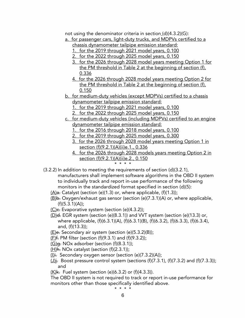
not using the denominator criteria in section (d)(4.3.2)(G):a. for passenger cars, light-duty trucks, and MDPVs certified to a
chassis dynamometer tailpipe emission standard:1. for the 2019 through 2021 model years, 0.1002. for the 2022 through 2025 model years, 0.1503. for the 2026 through 2028 model years meeting Option 1 for
the PM threshold in Table 2 at the beginning of section (f), 0.336
4. for the 2026 through 2028 model years meeting Option 2 for the PM threshold in Table 2 at the beginning of section (f), 0.150
b. for medium-duty vehicles (except MDPVs) certified to a chassis dynamometer tailpipe emission standard:1. for the 2019 through 2021 model years, 0.1002. for the 2022 through 2025 model years, 0.150
c. for medium-duty vehicles (including MDPVs) certified to an engine dynamometer tailpipe emission standard:1. for the 2016 through 2018 model years, 0.1002. for the 2019 through 2025 model years, 0.3003. for the 2026 through 2028 model years meeting Option 1 in
section (f)(9.2.1)(A)(ii)e.1., 0.3364. for the 2026 through 2028 models years meeting Option 2 in
section (f)(9.2.1)(A)(ii)e.2., 0.150* * * *
(3.2.2) In addition to meeting the requirements of section (d)(3.2.1), manufacturers shall implement software algorithms in the OBD II system to individually track and report in-use performance of the following monitors in the standardized format specified in section (d)(5):
(A)a. Catalyst (section (e)(1.3) or, where applicable, (f)(1.3));(B)b. Oxygen/exhaust gas sensor (section (e)(7.3.1)(A) or, where applicable,
(f)(5.3.1)(A));(C)c. Evaporative system (section (e)(4.3.2));(D)d. EGR system (section (e)(8.3.1)) and VVT system (section (e)(13.3) or,
where applicable, (f)(6.3.1)(A), (f)(6.3.1)(B), (f)(6.3.2), (f)(6.3.3), (f)(6.3.4), and, (f)(13.3));
(E)e. Secondary air system (section (e)(5.3.2)(B));(F)f. PM filter (section (f)(9.3.1) and (f)(9.3.2));(G)g. NOx adsorber (section (f)(8.3.1)); (H)h. NOx catalyst (section (f)(2.3.1));(I)i. Secondary oxygen sensor (section (e)(7.3.2)(A)); (J)j. Boost pressure control system (sections (f)(7.3.1), (f)(7.3.2) and (f)(7.3.3));
and(K)k. Fuel system (section (e)(6.3.2) or (f)(4.3.3)).The OBD II system is not required to track or report in-use performance for monitors other than those specifically identified above.
* * * *
7
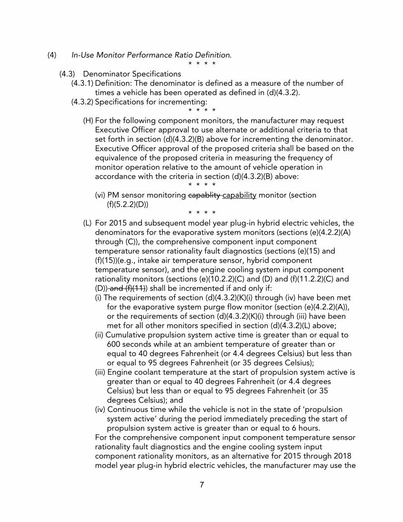
(4) In-Use Monitor Performance Ratio Definition.* * * *
(4.3) Denominator Specifications(4.3.1) Definition: The denominator is defined as a measure of the number of
times a vehicle has been operated as defined in (d)(4.3.2).(4.3.2) Specifications for incrementing:
* * * *(H) For the following component monitors, the manufacturer may request
Executive Officer approval to use alternate or additional criteria to that set forth in section (d)(4.3.2)(B) above for incrementing the denominator. Executive Officer approval of the proposed criteria shall be based on the equivalence of the proposed criteria in measuring the frequency of monitor operation relative to the amount of vehicle operation in accordance with the criteria in section (d)(4.3.2)(B) above:
* * * *(vi) PM sensor monitoring capablity capability monitor (section
(f)(5.2.2)(D))* * * *
(L) For 2015 and subsequent model year plug-in hybrid electric vehicles, the denominators for the evaporative system monitors (sections (e)(4.2.2)(A) through (C)), the comprehensive component input component temperature sensor rationality fault diagnostics (sections (e)(15) and (f)(15))(e.g., intake air temperature sensor, hybrid component temperature sensor), and the engine cooling system input component rationality monitors (sections (e)(10.2.2)(C) and (D) and (f)(11.2.2)(C) and (D)) and (f)(11)) shall be incremented if and only if:(i) The requirements of section (d)(4.3.2)(K)(i) through (iv) have been met
for the evaporative system purge flow monitor (section (e)(4.2.2)(A)), or the requirements of section (d)(4.3.2)(K)(i) through (iii) have been met for all other monitors specified in section (d)(4.3.2)(L) above;
(ii) Cumulative propulsion system active time is greater than or equal to 600 seconds while at an ambient temperature of greater than or equal to 40 degrees Fahrenheit (or 4.4 degrees Celsius) but less than or equal to 95 degrees Fahrenheit (or 35 degrees Celsius);
(iii) Engine coolant temperature at the start of propulsion system active is greater than or equal to 40 degrees Fahrenheit (or 4.4 degrees Celsius) but less than or equal to 95 degrees Fahrenheit (or 35 degrees Celsius); and
(iv) Continuous time while the vehicle is not in the state of ‘propulsion system active’ during the period immediately preceding the start of propulsion system active is greater than or equal to 6 hours.
For the comprehensive component input component temperature sensor rationality fault diagnostics and the engine cooling system input component rationality monitors, as an alternative for 2015 through 2018 model year plug-in hybrid electric vehicles, the manufacturer may use the
8
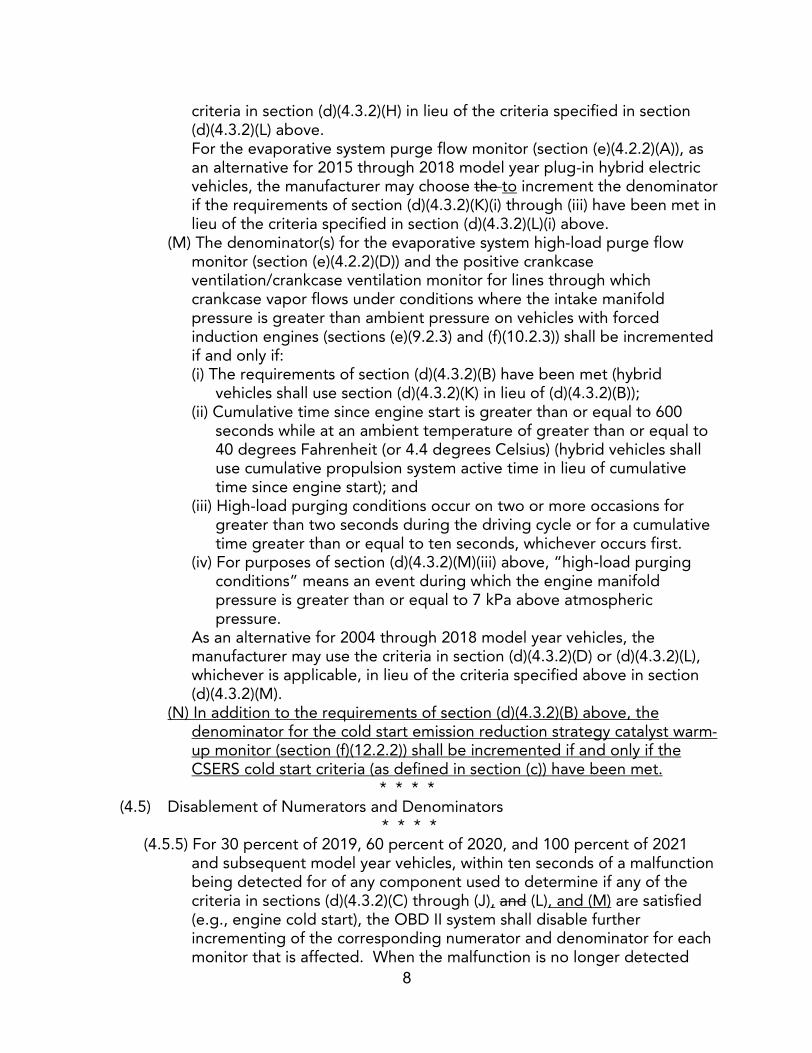
criteria in section (d)(4.3.2)(H) in lieu of the criteria specified in section (d)(4.3.2)(L) above.For the evaporative system purge flow monitor (section (e)(4.2.2)(A)), as an alternative for 2015 through 2018 model year plug-in hybrid electric vehicles, the manufacturer may choose the to increment the denominator if the requirements of section (d)(4.3.2)(K)(i) through (iii) have been met in lieu of the criteria specified in section (d)(4.3.2)(L)(i) above.
(M) The denominator(s) for the evaporative system high-load purge flow monitor (section (e)(4.2.2)(D)) and the positive crankcase ventilation/crankcase ventilation monitor for lines through which crankcase vapor flows under conditions where the intake manifold pressure is greater than ambient pressure on vehicles with forced induction engines (sections (e)(9.2.3) and (f)(10.2.3)) shall be incremented if and only if:(i) The requirements of section (d)(4.3.2)(B) have been met (hybrid
vehicles shall use section (d)(4.3.2)(K) in lieu of (d)(4.3.2)(B));(ii) Cumulative time since engine start is greater than or equal to 600
seconds while at an ambient temperature of greater than or equal to 40 degrees Fahrenheit (or 4.4 degrees Celsius) (hybrid vehicles shall use cumulative propulsion system active time in lieu of cumulative time since engine start); and
(iii) High-load purging conditions occur on two or more occasions for greater than two seconds during the driving cycle or for a cumulative time greater than or equal to ten seconds, whichever occurs first.
(iv) For purposes of section (d)(4.3.2)(M)(iii) above, “high-load purging conditions” means an event during which the engine manifold pressure is greater than or equal to 7 kPa above atmospheric pressure.
As an alternative for 2004 through 2018 model year vehicles, the manufacturer may use the criteria in section (d)(4.3.2)(D) or (d)(4.3.2)(L), whichever is applicable, in lieu of the criteria specified above in section (d)(4.3.2)(M).
(N) In addition to the requirements of section (d)(4.3.2)(B) above, the denominator for the cold start emission reduction strategy catalyst warm-up monitor (section (f)(12.2.2)) shall be incremented if and only if the CSERS cold start criteria (as defined in section (c)) have been met.
* * * *(4.5) Disablement of Numerators and Denominators
* * * *(4.5.5) For 30 percent of 2019, 60 percent of 2020, and 100 percent of 2021
and subsequent model year vehicles, within ten seconds of a malfunction being detected for of any component used to determine if any of the criteria in sections (d)(4.3.2)(C) through (J), and (L), and (M) are satisfied (e.g., engine cold start), the OBD II system shall disable further incrementing of the corresponding numerator and denominator for each monitor that is affected. When the malfunction is no longer detected
9
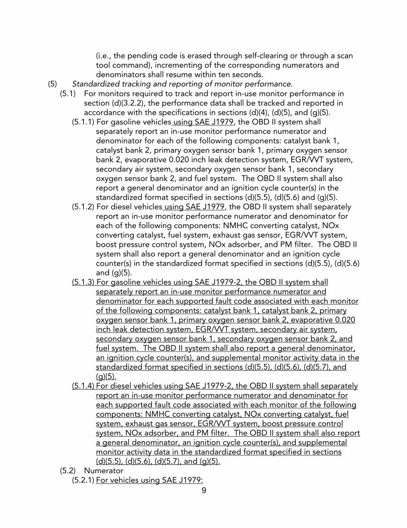
(i.e., the pending code is erased through self-clearing or through a scan tool command), incrementing of the corresponding numerators and denominators shall resume within ten seconds.
(5) Standardized tracking and reporting of monitor performance. (5.1) For monitors required to track and report in-use monitor performance in
section (d)(3.2.2), the performance data shall be tracked and reported in accordance with the specifications in sections (d)(4), (d)(5), and (g)(5).
(5.1.1) For gasoline vehicles using SAE J1979, the OBD II system shall separately report an in-use monitor performance numerator and denominator for each of the following components: catalyst bank 1, catalyst bank 2, primary oxygen sensor bank 1, primary oxygen sensor bank 2, evaporative 0.020 inch leak detection system, EGR/VVT system, secondary air system, secondary oxygen sensor bank 1, secondary oxygen sensor bank 2, and fuel system. The OBD II system shall also report a general denominator and an ignition cycle counter(s) in the standardized format specified in sections (d)(5.5), (d)(5.6) and (g)(5).
(5.1.2) For diesel vehicles using SAE J1979, the OBD II system shall separately report an in-use monitor performance numerator and denominator for each of the following components: NMHC converting catalyst, NOx converting catalyst, fuel system, exhaust gas sensor, EGR/VVT system, boost pressure control system, NOx adsorber, and PM filter. The OBD II system shall also report a general denominator and an ignition cycle counter(s) in the standardized format specified in sections (d)(5.5), (d)(5.6) and (g)(5).
(5.1.3) For gasoline vehicles using SAE J1979-2, the OBD II system shall separately report an in-use monitor performance numerator and denominator for each supported fault code associated with each monitor of the following components: catalyst bank 1, catalyst bank 2, primary oxygen sensor bank 1, primary oxygen sensor bank 2, evaporative 0.020 inch leak detection system, EGR/VVT system, secondary air system, secondary oxygen sensor bank 1, secondary oxygen sensor bank 2, and fuel system. The OBD II system shall also report a general denominator, an ignition cycle counter(s), and supplemental monitor activity data in the standardized format specified in sections (d)(5.5), (d)(5.6), (d)(5.7), and (g)(5).
(5.1.4) For diesel vehicles using SAE J1979-2, the OBD II system shall separately report an in-use monitor performance numerator and denominator for each supported fault code associated with each monitor of the following components: NMHC converting catalyst, NOx converting catalyst, fuel system, exhaust gas sensor, EGR/VVT system, boost pressure control system, NOx adsorber, and PM filter. The OBD II system shall also report a general denominator, an ignition cycle counter(s), and supplemental monitor activity data in the standardized format specified in sections (d)(5.5), (d)(5.6), (d)(5.7), and (g)(5).
(5.2) Numerator(5.2.1) For vehicles using SAE J1979:
10
(A) The OBD II system shall report a separate numerator for each of the components listed in section (d)(5.1).
(5.2.2)(B) For specific components or systems that have multiple monitors that are required to be reported under sections (e) or (f) (e.g., oxygen sensor bank 1 may have multiple monitors for sensor response or other sensor characteristics), the OBD II system shall separately track numerators and denominators for each of the specific monitors and report only the corresponding numerator and denominator for the specific monitor that has the lowest numerical ratio. If two or more specific monitors have identical ratios, the corresponding numerator and denominator for the specific monitor that has the highest denominator shall be reported for the specific component.
(5.2.3)(C) The numerator(s) shall be reported in accordance with the specifications in section (g)(5.2.1).
(5.2.2) For vehicles using SAE J1979-2:(A) Except as provided for in section (d)(5.2.2)(B) below, the OBD II system
shall report a separate numerator for each supported fault code associated with each monitor of the components listed in section (d)(5.1).
(B) For specific supported fault codes that have multiple monitors that are required to be reported under sections (e) or (f), the OBD II system shall separately track numerators and denominators for each of the monitors and report only the corresponding numerator and denominator for the specific supported fault code that has the lowest numerical ratio. If two or more specific monitors have identical ratios, the corresponding numerator and denominator for the specific monitor that has the highest denominator shall be reported for the specific supported fault code.
(C) The numerator(s) shall be reported in accordance with the specifications in section (g)(5.2.1).
(5.3) Denominator(5.3.1) For vehicles using SAE J1979:
(A) The OBD II system shall report a separate denominator for each of the components listed in section (d)(5.1).
(5.3.2)(B) The denominator(s) shall be reported in accordance with the specifications in section (g)(5.2.1).
(5.3.2) For vehicles using SAE J1979-2:(A) The OBD II system shall report a separate denominator for each
supported fault code associated with each monitor of the components listed in section (d)(5.1).
(B) The denominator(s) shall be reported in accordance with the specifications in section (g)(5.2.1).
(5.4) Ratio(5.4.1) For purposes of determining which corresponding numerator and
denominator to report as required in section (d)(5.2.21)(B) and (d)(5.2.2)(B), the ratio used for the determination shall be calculated in accordance with the specifications in section (g)(5.2.2).
* * * *
11
(5.7) Supplemental monitor activity data: For vehicles using SAE J1979-2, the OBD II system shall track and report the following data in accordance with SAE J1979-2 specifications for each diagnostic or emission-critical powertrain control unit:
(5.7.1) Mini-Numerator(A) Definition: The mini-numerator is defined as the counter that indicates
the number of driving cycles over which a monitor ran and completed since the last time the mini-denominator (defined below in section (d)(5.7.2)), was reset to zero. The OBD II system shall track and report a mini-numerator for each supported fault code that can illuminate the MIL.
(B) Specifications for incrementing: (i) The mini-numerator, when incremented, shall be incremented by an
integer of one. The mini-numerator may not be incremented more than once per driving cycle.
(ii) The mini-numerator shall be incremented at the end of a driving cycle if and only if the associated monitor ran and completed on the driving cycle.
(iii) The OBD II system shall pause further incrementing of the mini-numerator on a driving cycle if a malfunction has been detected which can illuminate the MIL as described in section (d)(2.2.2), and the diagnostic or emission-critical powertrain control unit that tracks and reports the mini-numerator stores a pending fault code for the malfunction. Incrementing of the mini-numerator shall resume for the next driving cycle in which no such fault code is present.
(iv) The OBD II system shall cease further incrementing of the mini-numerator if the mini-numerator has reached a value of 255.
(C) Specifications for resetting: The OBD II system shall reset the mini-numerator to zero at the same time the OBD II system resets the mini-denominator to zero as described below in section (d)(5.7.2).
(5.7.2) Mini-Denominator(A) Definition: The mini-denominator is defined as the counter that indicates
the number of general denominators that have accumulated since the last time the mini-denominator was reset to zero. The OBD II system shall track and report a mini-denominator for each diagnostic or emission-critical powertrain control unit.
(B) Specifications for incrementing: (i) The mini-denominator, when incremented, shall be incremented by an
integer of one. The mini-denominator may not be incremented more than once per driving cycle.
(ii) The mini-denominator for non-hybrid vehicles and hybrid vehicles that are not plug-in hybrid electric vehicles shall be incremented at the end of a driving cycle if and only if the general denominator increments during the driving cycle as described in section (d)(5.6.2). The mini-denominator for plug-in hybrid electric vehicles shall be incremented at the end of a driving cycle if and only if the criteria in
12
section (d)(4.3.2)(K)(i) through (iv) are satisfied during the driving cycle.
(iii) The OBD II system shall pause further incrementing of the mini-denominator on a driving cycle if a malfunction has been detected which can illuminate the MIL as described in section (d)(2.2.2) and the diagnostic or emission-critical powertrain control unit that tracks and reports the mini-denominator stores a pending fault code for the malfunction. Incrementing of the mini-denominator shall resume for the next driving cycle in which no such fault code is present.
(iv) The OBD II system shall cease further incrementing of the mini-denominator if the mini-denominator has reached a value of 255.
(C) Specifications for resetting: The OBD II system shall reset the mini-denominator to zero after the mini-denominator has reached a value of 255 and the OBD II system has updated the monitor activity ratio described below in section (d)(5.7.3). The reset shall occur before the beginning of the next driving cycle.
(5.7.3) Monitor Activity Ratio(A) Definition: The monitor activity ratio, or MAR, is defined as the ratio of
the mini-numerator to the mini-denominator when the mini-denominator reaches its maximum value of 255. The MAR has a minimum value of zero and a maximum value of one. The OBD II system shall track and report a MAR for each supported fault code that can illuminate the MIL.
(B) Specifications for updating: The MAR shall be updated only at the end of the same driving cycle in which the mini-denominator reaches a value of 255. The current value for the MAR shall be replaced with the new value.
(C) Specifications for resetting: The OBD II system may not reset the MAR to zero except under the conditions described below in section (d)(5.7.4).
(5.7.4) In addition to the specifications for resetting described above in sections (d)(5.7.1)(C), (d)(5.7.2)(C), and (d)(5.7.3)(C), the mini-numerator, mini-denominator, and MAR may be reset to zero only when a non-volatile memory reset occurs (e.g., reprogramming event) or, if the numbers are stored in KAM, when KAM is lost due to an interruption in electrical power to the control module (e.g., battery disconnect). Numbers may not be reset to zero under any other circumstances including when a scan tool command to clear fault codes or reset KAM is received.
* * * *(9) Implementation Schedule.
* * * *(9.2) SAE J1979 and SAE J1979-2 Implementation Schedule: For vehicles using
the ISO 15765-4 protocol as required in section (g)(3.4), the manufacturer shall implement SAE J1979 and SAE J1979-2 as follows:
(9.2.1) SAE J1979 Implementation: Except as provided below in section (d)(9.2.2), the manufacturer shall use SAE J1979 for the standardized
13
functions required in section 1968.2 for 2003 through 2026 model year vehicles.
(9.2.2) SAE J1979-2 Implementation: For 2027 and subsequent model year vehicles, the manufacturer shall use SAE J1979-2 for the standardized functions required in section 1968.2.
(A) For 2023 through 2026 model year vehicles, the manufacturer may use SAE J1979-2 in lieu of SAE J1979 for the standardized functions required in section 1968.2.
(B) The manufacturer may not use SAE 1979-2 for the standardized functions required in section 1968.2 on 2022 and earlier model year vehicles.
* * * *(e) Monitoring Requirements for Gasoline/Spark-Ignited Engines.
For non-Low Emission Vehicle III applications (e.g., Low Emission Vehicle applications and Low Emission Vehicle II applications), the emission thresholds are specified in the monitoring sections in section (e) below. For Low Emission Vehicle III applications, wherever an emission threshold for a malfunction on a diagnostic is required in section (e), the emission thresholds shall be set in accordance with Table 1 below:
* * * *(1) Catalyst Monitoring
* * * *(1.3) Monitoring Conditions: Manufacturers shall define the monitoring conditions
for malfunctions identified in section (e)(1.2) in accordance with sections (d)(3.1) and (d)(3.2) (i.e., minimum ratio requirements). Additionally, manufacturers shall track and report the in-use performance of the catalyst monitor under section (e)(1.2) in accordance with section (d)(3.2.2).
(1.3.1) For vehicles using SAE J1979, fFor purposes of tracking and reporting as required in section (d)(3.2.2), all monitors used to detect malfunctions identified in section (e)(1.2) shall be tracked separately but reported as a single set of values as specified in section (d)(5.2.21)(B).
(1.3.2) For vehicles using SAE J1979-2, for purposes of tracking and reporting as required in section (d)(3.2.2), all monitors used to detect malfunctions identified in section (e)(1.2) shall be tracked and reported separately as specified in section (d)(5.1.3) or tracked separately but reported as a single set of values as specified in section (d)(5.2.2)(B), whichever is applicable.
* * * *(3) Misfire Monitoring
* * * *(3.4) MIL Illumination and Fault Code Storage:
(3.4.1) Misfire causing catalyst damage. Upon detection of the percentage of misfire specified in section (e)(3.2.1) above, the following criteria shall apply for MIL illumination and fault code storage:
* * * *(A) Confirmed fault codes
* * * *
14
(ii) If a pending fault code for exceeding the percentage of misfire set forth in section (e)(3.2.2) is stored from a previous drive driving cycle, the OBD II system shall immediately store a confirmed fault code if the percentage of misfire specified in section (e)(3.2.1) is exceeded one or more times regardless of the conditions encountered.
* * * *(3.4.4) Storage of freeze frame conditions.
(A) For vehicles using SAE J1979:(i) A manufacturer shall store and erase freeze frame conditions either in
conjunction with storing and erasing a pending fault code or in conjunction with storing and erasing a confirmed fault code.
(B)(ii) If freeze frame conditions are stored for a malfunction other than misfire or fuel system malfunction (see section (e)(6)) when a misfire fault code is stored as specified in section (e)(3.4) above, the stored freeze frame information shall be replaced with freeze frame information regarding the misfire malfunction.
(B) For vehicles using SAE J1979-2: A manufacturer shall store and erase freeze frame conditions in accordance with section (d)(2.2.7)(B).
* * * *(4) Evaporative System Monitoring
* * * *(4.3) Monitoring Conditions:
* * * *(4.3.2) Manufacturers shall define the monitoring conditions for malfunctions
identified in section (e)(4.2.2)(C) (i.e., 0.020 inch leak detection) in accordance with sections (d)(3.1) and (d)(3.2) (i.e., minimum ratio requirements). Additionally, manufacturers shall track and report the in-use performance of the evaporative system monitors under section (e)(4.2.2)(C) in accordance with section (d)(3.2.2).
(A) For vehicles using SAE J1979, fFor purposes of tracking and reporting as required in section (d)(3.2.2), all monitors used to detect malfunctions identified in section (e)(4.2.2)(C) shall be tracked separately but reported as a single set of values as specified in section (d)(5.2.21)(B).
(B) For vehicles using SAE J1979-2, for purposes of tracking and reporting as required in section (d)(3.2.2), all monitors used to detect malfunctions identified in section (e)(4.2.2)(C) shall be tracked and reported separately as specified in section (d)(5.1.3) or tracked separately but reported as a single set of values as specified in section (d)(5.2.2)(B), whichever is applicable.
* * * *(5) Secondary Air System Monitoring
* * * *(5.3) Monitoring Conditions:
* * * *(5.3.2) For all Low Emission Vehicle II applications and all 2009 and subsequent
model year vehicles:
15
(A) For 2004 and 2005 model year vehicles, manufacturers shall define the monitoring conditions in accordance with section (d)(3.1).
(B) For 2006 and subsequent model year vehicles, manufacturers shall define the monitoring conditions in accordance with sections (d)(3.1) and (d)(3.2) (i.e., minimum ratio requirements). Additionally, manufacturers shall track and report the in-use performance of the secondary air system monitors under section (e)(5.2) in accordance with section (d)(3.2.2). (i) For vehicles using J1979, fFor purposes of tracking and reporting as
required in section (d)(3.2.2), all monitors used to detect malfunctions identified in section (e)(5.2) during normal operation of the secondary air system shall be tracked separately but reported as a single set of values as specified in section (d)(5.2.21)(B).
(ii) For vehicles using SAE J1979-2, for purposes of tracking and reporting as required in section (d)(3.2.2), all monitors used to detect malfunctions identified in section (e)(5.2) during normal operation of the secondary air system shall be tracked and reported separately as specified in section (d)(5.1.3) or tracked separately but reported as a single set of values as specified in section (d)(5.2.2)(B), whichever is applicable.
* * * *(6) Fuel System Monitoring
* * * *(6.3) Monitoring Conditions:
* * * *(6.3.2) Manufacturers shall define monitoring conditions for malfunctions
identified in section (e)(6.2.1)(C) (i.e., air-fuel ratio cylinder imbalance malfunctions) in accordance with sections (d)(3.1) and (d)(3.2) (i.e., minimum ratio requirements). Additionally, for 30 percent of 2019, 60 percent of 2020, and 100 percent of 2021 and subsequent model year gasoline vehicles, manufacturers shall track and report the in-use performance of the fuel system monitors under section (e)(6.2.1)(C) in accordance with section (d)(3.2.2). Manufacturers that use other existing monitors (e.g., misfire monitor under section (e)(3), fuel system monitor under section (e)(6.2.1)(A)) to detect malfunctions identified in section (e)(6.2.1)(C) are subject to the tracking and reporting requirements of the other monitors.
(A) For vehicles using SAE J1979, fFor purposes of tracking and reporting as required in section (d)(3.2.2), all dedicated monitors used to detect malfunctions identified in section (e)(6.2.1)(C) shall be tracked separately but reported as a single set of values as specified in section (d)(5.2.21)(B). Manufacturers that use other existing monitors (e.g., misfire monitor under section (e)(3), fuel system monitor under section (e)(6.2.1)(A)) to detect malfunctions identified in section (e)(6.2.1)(C) are subject to the tracking and reporting requirements of the other monitors.
(B) For vehicles using SAE J1979-2, for purposes of tracking and reporting as required in section (d)(3.2.2), all dedicated monitors used to detect

16
malfunctions identified in section (e)(6.2.1)(C) shall be tracked and reported separately as specified in section (d)(5.1.3) or tracked separately but reported as a single set of values as specified in section (d)(5.2.2)(B), whichever is applicable.
(6.3.3) Manufacturers shall define monitoring conditions for malfunctions identified in section (e)(6.2.4) (except malfunctions identified in section (e)(6.4.26.2.4)(C), which is provided for per section (e)(6.3.4) below) in accordance with section (d)(3.1).
* * * *(6.4.4) Storage of freeze frame conditions.
(A) For vehicles using SAE J1979:(i) The OBD II system shall store and erase freeze frame conditions
either in conjunction with storing and erasing a pending fault code or in conjunction with storing and erasing a confirmed fault code.
(B)(ii) If freeze frame conditions are stored for a malfunction other than misfire (see section (e)(3)) or fuel system malfunction when a fuel system fault code is stored as specified in section (e)(6.4) above, the stored freeze frame information shall be replaced with freeze frame information regarding the fuel system malfunction.
(B) For vehicles using SAE J1979-2: A manufacturer shall store and erase freeze frame conditions in accordance with section (d)(2.2.7)(B).
* * * *(7) Exhaust Gas Sensor Monitoring
* * * *(7.3) Monitoring Conditions:
(7.3.1) Primary Sensors(A) Manufacturers shall define the monitoring conditions for malfunctions
identified in sections (e)(7.2.1)(A) and (D) (e.g., proper response rate) in accordance with sections (d)(3.1) and (d)(3.2) (i.e., minimum ratio requirements). Additionally, manufacturers shall track and report the in-use performance of the primary sensor monitors under sections (e)(7.2.1)(A) and (D) in accordance with section (d)(3.2.2). (i) For vehicles using SAE J1979, fFor purposes of tracking and reporting
as required in section (d)(3.2.2), all monitors used to detect malfunctions identified in sections (e)(7.2.1)(A) and (D) shall be tracked separately but reported as a single set of values as specified in section (d)(5.2.21)(B).
(ii) For vehicles using SAE J1979-2, for purposes of tracking and reporting as required in section (d)(3.2.2), all monitors used to detect malfunctions identified in sections (e)(7.2.1)(A) and (D) shall be tracked and reported separately as specified in section (d)(5.1.3) or tracked separately but reported as a single set of values as specified in section (d)(5.2.2)(B), whichever is applicable.
* * * *(7.3.2) Secondary Sensors
(A) Manufacturers shall define monitoring conditions for malfunctions
17
identified in sections (e)(7.2.2)(A) and (C) (e.g., proper sensor activity) in accordance with sections (d)(3.1) and (d)(3.2) (i.e., minimum ratio requirements). Additionally, for all 2010 and subsequent model year vehicles meeting the monitoring requirements of section (e)(7.2.2)(C)(i) or (ii), manufacturers shall track and report the in-use performance of the secondary sensor monitors under (e)(7.2.2)(A) and (C) in accordance with section (d)(3.2.2). (i) For vehicles using J1979, fFor purposes of tracking and reporting as
required in section (d)(3.2.2), all monitors used to detect malfunctions identified in sections (e)(7.2.2)(A) and (C) shall be tracked separately but reported as a single set of values as specified in section (d)(5.2.21)(B).
(ii) For vehicles using SAE J1979-2, for purposes of tracking and reporting as required in section (d)(3.2.2), all monitors used to detect malfunctions identified in sections (e)(7.2.2)(A) and (C) shall be tracked and reported separately as specified in section (d)(5.1.3) or tracked separately but reported as a single set of values as specified in section (d)(5.2.2)(B), whichever is applicable.
* * * *(8) Exhaust Gas Recirculation (EGR) System Monitoring
* * * *(8.3) Monitoring Conditions:
(8.3.1) Manufacturers shall define the monitoring conditions for malfunctions identified in section (e)(8.2) (e.g., flow rate) in accordance with sections (d)(3.1) and (d)(3.2) (i.e., minimum ratio requirements). Additionally, manufacturers shall track and report the in-use performance of the EGR system monitors under section (e)(8.2) in accordance with section (d)(3.2.2).
(A) For vehicles using SAE J1979, fFor purposes of tracking and reporting as required in section (d)(3.2.2), all monitors used to detect malfunctions identified in section (e)(8.2) shall be tracked separately but reported as a single set of values as specified in section (d)(5.2.21)(B).
(B) For vehicles using SAE J1979-2, for purposes of tracking and reporting as required in section (d)(3.2.2), all monitors used to detect malfunctions identified in section (e)(8.2) shall be tracked and reported separately as specified in section (d)(5.1.3) or tracked separately but reported as a single set of values as specified in section (d)(5.2.2)(B), whichever is applicable.
* * * *(11) Cold Start Emission Reduction Strategy Monitoring
* * * *(11.2) Malfunction Criteria:
* * * *(11.2.2) For 25 percent of 2010, 50 percent of 2011, and 100 percent of 2012
and subsequent through 2025 model year vehicles, the OBD II system
18
shall, to the extent feasible, detect a malfunction if either of the following occurs:
(A) Any single commanded element/component does not properly respond to the commanded action while the cold start strategy is active. For elements/components involving spark timing (e.g., retarded spark timing), the monitor may verify final commanded spark timing in lieu of verifying actual delivered spark timing. For purposes of this section, “properly respond” is defined as when the element/component responds:(i) by a robustly detectable amount; and (ii) in the direction of the desired command; and(iii) above and beyond what the element/component would achieve on
start-up without the cold start strategy active (e.g., if the cold start strategy commands a higher idle engine speed, a fault must be detected if there is no detectable amount of engine speed increase above what the system would achieve without the cold start strategy active);
(B) Any failure or deterioration of the cold start emission reduction control strategy while the cold start strategy is active that would cause a vehicle’s emissions to be equal to or above the emission thresholds in sections (e)(11.2.2)(B)(i) or (ii) below. For this requirement, the OBD II system shall either monitor elements/components of the system as a whole (e.g., measuring air flow and modeling overall heat into the exhaust) or the individual elements/components (e.g., increased engine speed, commanded final spark timing) for failures that cause vehicle emissions to exceed the emission thresholds in sections (e)(11.2.2)(B)(i) or (ii) below. (i) For non-Low Emission Vehicle III applications, the threshold is 1.5
times the applicable FTP standards.(ii) For Low Emission Vehicle III applications, the thresholds are any of the
applicable emission thresholds set forth in Table 1 in the beginning of section (e).
(11.2.3) Cold Start Catalyst Heating Monitor: For 2026 and subsequent model year vehicles utilizing catalyst heating through combustion inefficiency during idle at cold start, except as provided for in section (e)(11.2.3)(C), the OBD II system shall monitor the commanded (or delivered, if feasible) extra cold start exhaust heat energy directed to the catalyst. The monitor shall begin when the engine starts and the conditions of the CSERS cold start criteria (as defined in section (c)) are met, and shall continue no longer than 30 seconds after engine start. Monitoring is not required if the idle operation during the first 30 seconds after engine start is less than 10 seconds.
(A) The OBD II system shall detect a malfunction of the extra cold start exhaust heat energy delivery to the catalyst when any of the following occurs:
19
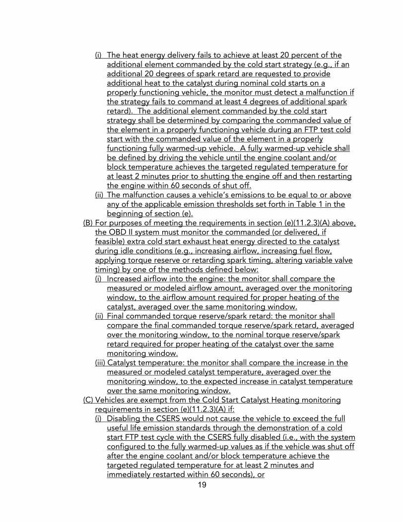
(i) The heat energy delivery fails to achieve at least 20 percent of the additional element commanded by the cold start strategy (e.g., if an additional 20 degrees of spark retard are requested to provide additional heat to the catalyst during nominal cold starts on a properly functioning vehicle, the monitor must detect a malfunction if the strategy fails to command at least 4 degrees of additional spark retard). The additional element commanded by the cold start strategy shall be determined by comparing the commanded value of the element in a properly functioning vehicle during an FTP test cold start with the commanded value of the element in a properly functioning fully warmed-up vehicle. A fully warmed-up vehicle shall be defined by driving the vehicle until the engine coolant and/or block temperature achieves the targeted regulated temperature for at least 2 minutes prior to shutting the engine off and then restarting the engine within 60 seconds of shut off.
(ii) The malfunction causes a vehicle’s emissions to be equal to or above any of the applicable emission thresholds set forth in Table 1 in the beginning of section (e).
(B) For purposes of meeting the requirements in section (e)(11.2.3)(A) above, the OBD II system must monitor the commanded (or delivered, if feasible) extra cold start exhaust heat energy directed to the catalyst during idle conditions (e.g., increasing airflow, increasing fuel flow, applying torque reserve or retarding spark timing, altering variable valve timing) by one of the methods defined below:(i) Increased airflow into the engine: the monitor shall compare the
measured or modeled airflow amount, averaged over the monitoring window, to the airflow amount required for proper heating of the catalyst, averaged over the same monitoring window.
(ii) Final commanded torque reserve/spark retard: the monitor shall compare the final commanded torque reserve/spark retard, averaged over the monitoring window, to the nominal torque reserve/spark retard required for proper heating of the catalyst over the same monitoring window.
(iii) Catalyst temperature: the monitor shall compare the increase in the measured or modeled catalyst temperature, averaged over the monitoring window, to the expected increase in catalyst temperature over the same monitoring window.
(C) Vehicles are exempt from the Cold Start Catalyst Heating monitoring requirements in section (e)(11.2.3)(A) if:(i) Disabling the CSERS would not cause the vehicle to exceed the full
useful life emission standards through the demonstration of a cold start FTP test cycle with the CSERS fully disabled (i.e., with the system configured to the fully warmed-up values as if the vehicle was shut off after the engine coolant and/or block temperature achieve the targeted regulated temperature for at least 2 minutes and immediately restarted within 60 seconds), or
20
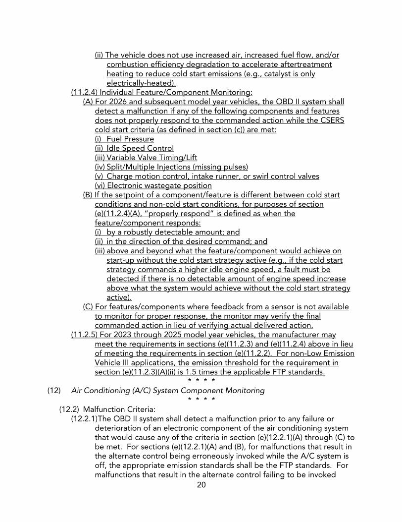
(ii) The vehicle does not use increased air, increased fuel flow, and/or combustion efficiency degradation to accelerate aftertreatment heating to reduce cold start emissions (e.g., catalyst is only electrically-heated).
(11.2.4) Individual Feature/Component Monitoring:(A) For 2026 and subsequent model year vehicles, the OBD II system shall
detect a malfunction if any of the following components and features does not properly respond to the commanded action while the CSERS cold start criteria (as defined in section (c)) are met: (i) Fuel Pressure(ii) Idle Speed Control(iii) Variable Valve Timing/Lift(iv) Split/Multiple Injections (missing pulses)(v) Charge motion control, intake runner, or swirl control valves(vi) Electronic wastegate position
(B) If the setpoint of a component/feature is different between cold start conditions and non-cold start conditions, for purposes of section (e)(11.2.4)(A), “properly respond” is defined as when the feature/component responds:(i) by a robustly detectable amount; and (ii) in the direction of the desired command; and (iii) above and beyond what the feature/component would achieve on
start-up without the cold start strategy active (e.g., if the cold start strategy commands a higher idle engine speed, a fault must be detected if there is no detectable amount of engine speed increase above what the system would achieve without the cold start strategy active).
(C) For features/components where feedback from a sensor is not available to monitor for proper response, the monitor may verify the final commanded action in lieu of verifying actual delivered action.
(11.2.5) For 2023 through 2025 model year vehicles, the manufacturer may meet the requirements in sections (e)(11.2.3) and (e)(11.2.4) above in lieu of meeting the requirements in section (e)(11.2.2). For non-Low Emission Vehicle III applications, the emission threshold for the requirement in section (e)(11.2.3)(A)(ii) is 1.5 times the applicable FTP standards.
* * * *(12) Air Conditioning (A/C) System Component Monitoring
* * * *(12.2) Malfunction Criteria:
(12.2.1) The OBD II system shall detect a malfunction prior to any failure or deterioration of an electronic component of the air conditioning system that would cause any of the criteria in section (e)(12.2.1)(A) through (C) to be met. For sections (e)(12.2.1)(A) and (B), for malfunctions that result in the alternate control being erroneously invoked while the A/C system is off, the appropriate emission standards shall be the FTP standards. For malfunctions that result in the alternate control failing to be invoked

21
while the A/C system is on, the appropriate emission standards shall be the SC03 emission standards.
(A) For non-Low Emission Vehicle III applications, the OBD II system shall detect a malfunction that causes a vehicle’s emissions to exceed 1.5 times any of the appropriate applicable emissions standards.
(B) For Low Emission Vehicle III applications, the OBD II system shall detect a malfunction that causes a vehicle’s emissions to exceed any of the applicable emission thresholds set forth in Table 1 in the beginning of section (e).
(C) For all vehicles, the OBD II system shall detect a malfunction if, through software, the malfunction effectively disables the monitors of any other monitored system or component covered by this regulation.
* * * *(13) Variable Valve Timing, Lift, and/or Control (VVT) System Monitoring
* * * *(13.3) Monitoring Conditions: Manufacturers shall define the monitoring conditions
for VVT system malfunctions identified in section (e)(13.2) in accordance with sections (d)(3.1) and (d)(3.2) (i.e., minimum ratio requirements), with the exception that monitoring shall occur every time the monitoring conditions are met during the driving cycle in lieu of once per driving cycle as required in section (d)(3.1.2). Additionally, manufacturers shall track and report the in-use performance of the VVT system monitors under section (e)(13.2) in accordance with section (d)(3.2.2).
(13.3.1) For vehicles using SAE J1979, fFor purposes of tracking and reporting as required in section (d)(3.2.2), all monitors used to detect malfunctions identified in section (e)(13.2) shall be tracked separately but reported as a single set of values as specified in section (d)(5.2.21)(B).
(13.3.2) For vehicles using SAE J1979-2, for purposes of tracking and reporting as required in section (d)(3.2.2), all monitors used to detect malfunctions identified in section (e)(13.2) shall be tracked and reported separately as specified in section (d)(5.1.3) or tracked separately but reported as a single set of values as specified in section (d)(5.2.2)(B), whichever is applicable.
* * * *(15) Comprehensive Component Monitoring
* * * *(15.2) Malfunction Criteria:
* * * *(15.2.2) Output Components/Systems:
* * * *(B) The idle speed control system shall be monitored for proper functional
response to computer commands. For strategies based on deviation from target idle speed, a malfunction shall be detected when eitherany of the following conditions occur:(i) The idle speed control system cannot achieve the target idle speed
within 200 revolutions per minute (rpm) above the target speed or
22
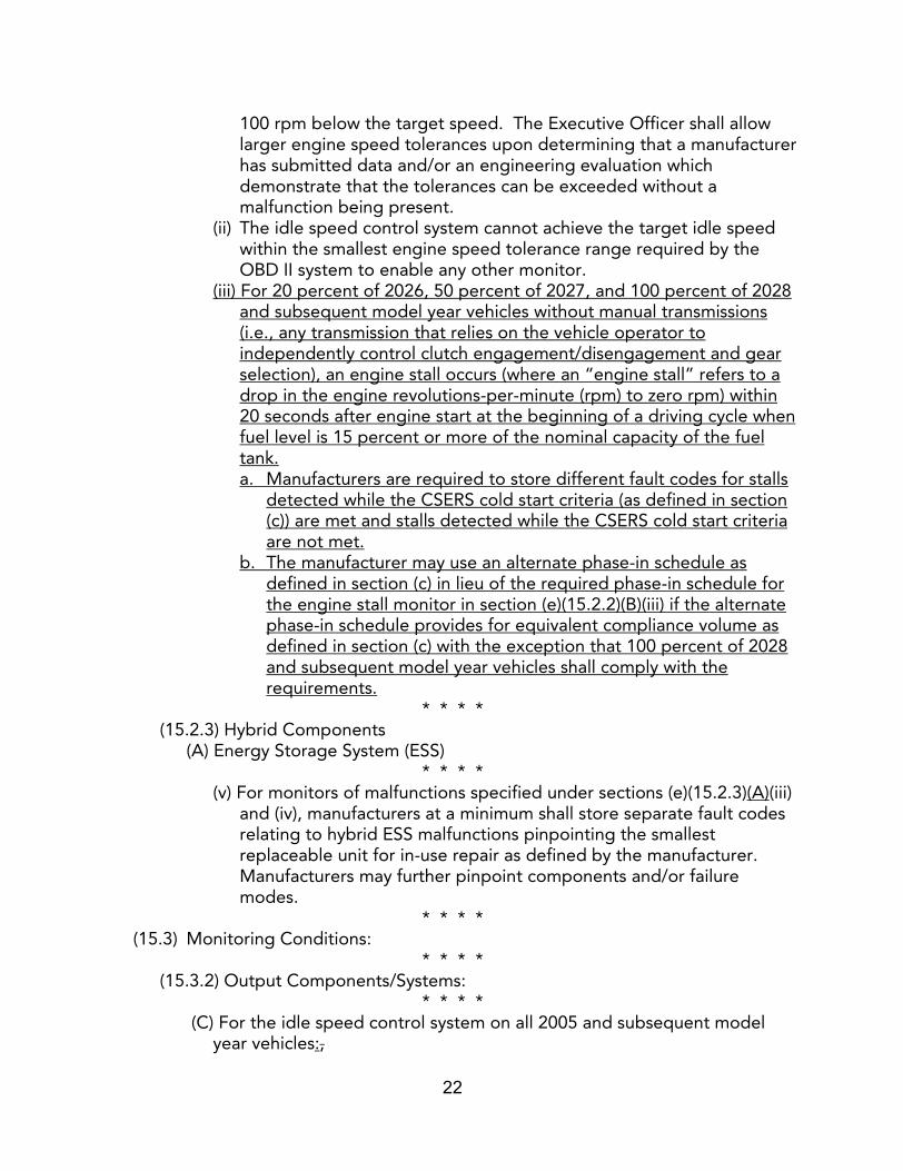
100 rpm below the target speed. The Executive Officer shall allow larger engine speed tolerances upon determining that a manufacturer has submitted data and/or an engineering evaluation which demonstrate that the tolerances can be exceeded without a malfunction being present.
(ii) The idle speed control system cannot achieve the target idle speed within the smallest engine speed tolerance range required by the OBD II system to enable any other monitor.
(iii) For 20 percent of 2026, 50 percent of 2027, and 100 percent of 2028 and subsequent model year vehicles without manual transmissions (i.e., any transmission that relies on the vehicle operator to independently control clutch engagement/disengagement and gear selection), an engine stall occurs (where an “engine stall” refers to a drop in the engine revolutions-per-minute (rpm) to zero rpm) within 20 seconds after engine start at the beginning of a driving cycle when fuel level is 15 percent or more of the nominal capacity of the fuel tank. a. Manufacturers are required to store different fault codes for stalls
detected while the CSERS cold start criteria (as defined in section (c)) are met and stalls detected while the CSERS cold start criteria are not met.
b. The manufacturer may use an alternate phase-in schedule as defined in section (c) in lieu of the required phase-in schedule for the engine stall monitor in section (e)(15.2.2)(B)(iii) if the alternate phase-in schedule provides for equivalent compliance volume as defined in section (c) with the exception that 100 percent of 2028 and subsequent model year vehicles shall comply with the requirements.
* * * *(15.2.3) Hybrid Components
(A) Energy Storage System (ESS) * * * *
(v) For monitors of malfunctions specified under sections (e)(15.2.3)(A)(iii) and (iv), manufacturers at a minimum shall store separate fault codes relating to hybrid ESS malfunctions pinpointing the smallest replaceable unit for in-use repair as defined by the manufacturer. Manufacturers may further pinpoint components and/or failure modes.
* * * *(15.3) Monitoring Conditions:
* * * *(15.3.2) Output Components/Systems:
* * * *(C) For the idle speed control system on all 2005 and subsequent model
year vehicles:,
23
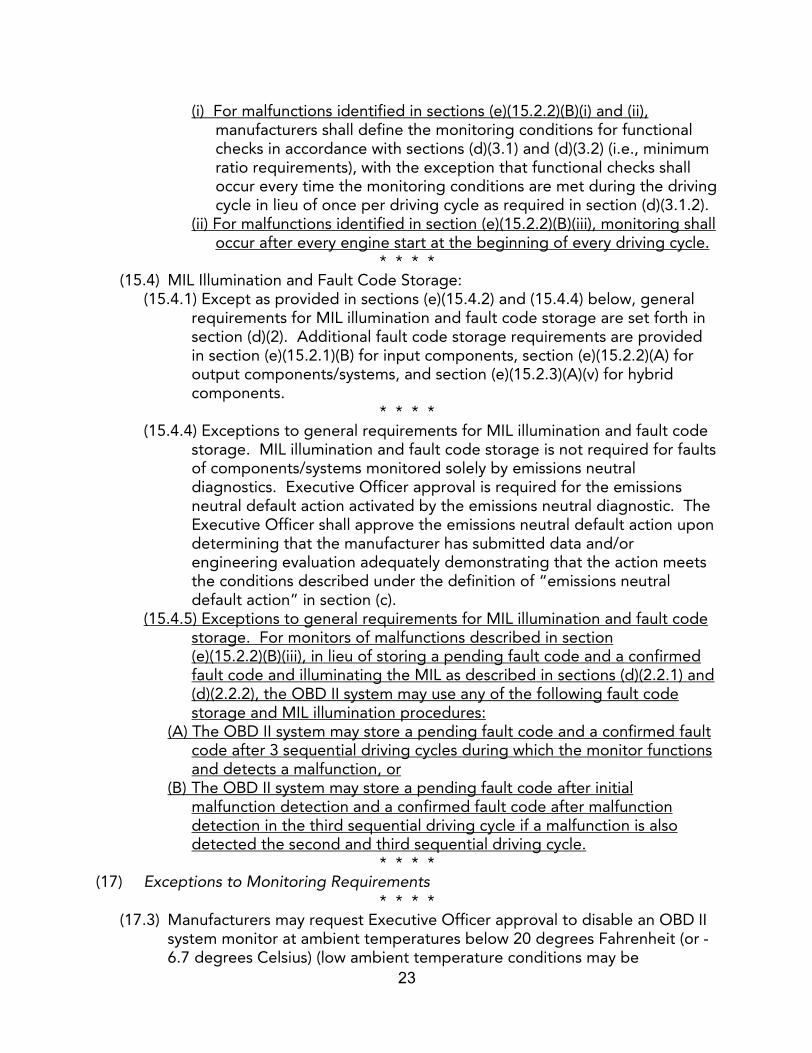
(i) For malfunctions identified in sections (e)(15.2.2)(B)(i) and (ii), manufacturers shall define the monitoring conditions for functional checks in accordance with sections (d)(3.1) and (d)(3.2) (i.e., minimum ratio requirements), with the exception that functional checks shall occur every time the monitoring conditions are met during the driving cycle in lieu of once per driving cycle as required in section (d)(3.1.2).
(ii) For malfunctions identified in section (e)(15.2.2)(B)(iii), monitoring shall occur after every engine start at the beginning of every driving cycle.
* * * *(15.4) MIL Illumination and Fault Code Storage:
(15.4.1) Except as provided in sections (e)(15.4.2) and (15.4.4) below, general requirements for MIL illumination and fault code storage are set forth in section (d)(2). Additional fault code storage requirements are provided in section (e)(15.2.1)(B) for input components, section (e)(15.2.2)(A) for output components/systems, and section (e)(15.2.3)(A)(v) for hybrid components.
* * * *(15.4.4) Exceptions to general requirements for MIL illumination and fault code
storage. MIL illumination and fault code storage is not required for faults of components/systems monitored solely by emissions neutral diagnostics. Executive Officer approval is required for the emissions neutral default action activated by the emissions neutral diagnostic. The Executive Officer shall approve the emissions neutral default action upon determining that the manufacturer has submitted data and/or engineering evaluation adequately demonstrating that the action meets the conditions described under the definition of “emissions neutral default action” in section (c).
(15.4.5) Exceptions to general requirements for MIL illumination and fault code storage. For monitors of malfunctions described in section (e)(15.2.2)(B)(iii), in lieu of storing a pending fault code and a confirmed fault code and illuminating the MIL as described in sections (d)(2.2.1) and (d)(2.2.2), the OBD II system may use any of the following fault code storage and MIL illumination procedures:
(A) The OBD II system may store a pending fault code and a confirmed fault code after 3 sequential driving cycles during which the monitor functions and detects a malfunction, or
(B) The OBD II system may store a pending fault code after initial malfunction detection and a confirmed fault code after malfunction detection in the third sequential driving cycle if a malfunction is also detected the second and third sequential driving cycle.
* * * *(17) Exceptions to Monitoring Requirements
* * * *(17.3) Manufacturers may request Executive Officer approval to disable an OBD II
system monitor at ambient temperatures below 20 degrees Fahrenheit (or -6.7 degrees Celsius) (low ambient temperature conditions may be
24
determined based on intake air or engine coolant temperature) or at elevations above 8000 feet above sea level. The Executive Officer shall approve the request upon determining that the manufacturer has provided data and/or an engineering evaluation that demonstrate that monitoring during the conditions would be unreliable. A manufacturer may further request, and the Executive Officer shall approve, that an OBD II system monitor be disabled at other ambient temperatures or altitudes upon determining that the manufacturer has demonstrated with data and/or an engineering evaluation that misdiagnosis would occur at the ambient temperatures or altitudes because of its effect on the component itself (e.g., component freezing).
* * * *(f) Monitoring Requirements for Diesel/Compression-Ignition Engines.
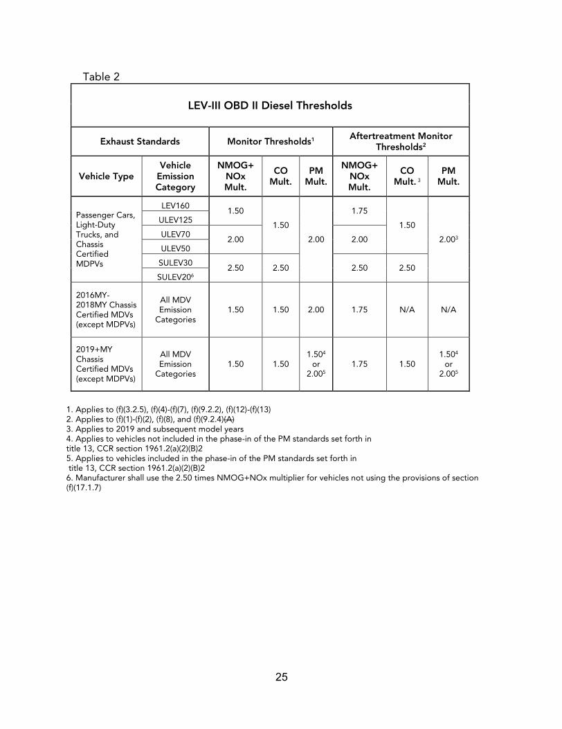
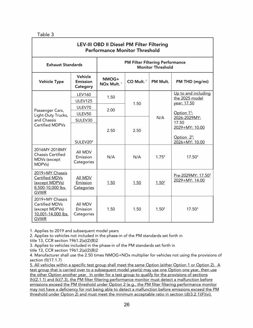
For non-Low Emission Vehicle III applications (e.g., Low Emission Vehicle applications and Low Emission Vehicle II applications), the emission thresholds are specified in the monitoring sections in section (f) below. For Low Emission Vehicle III applications, wherever an emission threshold for a malfunction on a diagnostic is required in section (f), the emission thresholds shall be set in accordance with Table 2 and Table 3 below:
25
Table 2
LEV-III OBD II Diesel Thresholds
Exhaust Standards Monitor Thresholds1 Aftertreatment Monitor Thresholds2
Vehicle TypeVehicle
Emission Category
NMOG+ NOx Mult.
CO Mult.
PM Mult.
NMOG+ NOx Mult.
CO Mult. 3
PM Mult.
Passenger Cars, Light-Duty Trucks, and Chassis Certified MDPVs
LEV1601.50
1.50
2.00
1.75
1.50
2.003
ULEV125
ULEV702.00 2.00
ULEV50
SULEV302.50 2.50 2.50 2.50
SULEV206
2016MY-2018MY Chassis Certified MDVs (except MDPVs)
All MDV Emission
Categories1.50 1.50 2.00 1.75 N/A N/A
2019+MY Chassis Certified MDVs (except MDPVs)
All MDV Emission
Categories1.50 1.50
1.504
or 2.005
1.75 1.501.504
or 2.005
1. Applies to (f)(3.2.5), (f)(4)-(f)(7), (f)(9.2.2), (f)(12)-(f)(13)2. Applies to (f)(1)-(f)(2), (f)(8), and (f)(9.2.4)(A)3. Applies to 2019 and subsequent model years4. Applies to vehicles not included in the phase-in of the PM standards set forth in title 13, CCR section 1961.2(a)(2)(B)25. Applies to vehicles included in the phase-in of the PM standards set forth in title 13, CCR section 1961.2(a)(2)(B)26. Manufacturer shall use the 2.50 times NMOG+NOx multiplier for vehicles not using the provisions of section (f)(17.1.7)
26
Table 3
LEV-III OBD II Diesel PM Filter Filtering Performance Monitor Threshold
Exhaust Standards PM Filter Filtering Performance Monitor Threshold
Vehicle TypeVehicle
Emission Category
NMOG+NOx Mult. 1 CO Mult. 1 PM Mult. PM THD (mg/mi)
Passenger Cars, Light-Duty Trucks, and Chassis Certified MDPVs
LEV1601.50
1.50
N/A
Up to and including the 2025 model year: 17.50
Option 15: 2026-2029MY: 17.502029+MY: 10.00
Option 25:2026+MY: 10.00
ULEV125
ULEV702.00
ULEV50
SULEV30
2.50 2.50
SULEV204
2016MY-2018MY Chassis Certified MDVs (except MDPVs)
All MDV Emission
CategoriesN/A N/A 1.752 17.503
2019+MY Chassis Certified MDVs (except MDPVs)8,500-10,000 lbs. GVWR
All MDV Emission
Categories1.50 1.50 1.502
Pre-2029MY: 17.503
2029+MY: 14.00
2019+MY Chassis Certified MDVs (except MDPVs) 10,001-14,000 lbs. GVWR
All MDV Emission
Categories1.50 1.50 1.502 17.503
1. Applies to 2019 and subsequent model years2. Applies to vehicles not included in the phase-in of the PM standards set forth in title 13, CCR section 1961.2(a)(2)(B)23. Applies to vehicles included in the phase-in of the PM standards set forth in title 13, CCR section 1961.2(a)(2)(B)24. Manufacturer shall use the 2.50 times NMOG+NOx multiplier for vehicles not using the provisions of section (f)(17.1.7)5. All vehicles within a specific test group shall meet the same Option (either Option 1 or Option 2). A test group that is carried over to a subsequent model year(s) may use one Option one year, then use the other Option another year. In order for a test group to qualify for the provisions of sections (h)(2.1.1) and (k)(7.3), the PM filter filtering performance monitor must detect a malfunction before emissions exceed the PM threshold under Option 2 (e.g., the PM filter filtering performance monitor may not have a deficiency for not being able to detect a malfunction before emissions exceed the PM threshold under Option 2) and must meet the minimum acceptable ratio in section (d)(3.2.1)(F)(vi).

27
(1) Non-Methane Hydrocarbon (NMHC) Converting Catalyst Monitoring* * * *
(1.2) Malfunction Criteria:* * * *
(1.2.3) Other Aftertreatment Assistance Functions. Additionally, for 2010 and subsequent model year vehicles, the catalyst(s) shall be monitored for other aftertreatment assistance functions:
* * * *(B) Feedgas generation:
(i) For 2015 and subsequent through 2024 model year passenger cars, light-duty trucks, and MDPVs certified to a chassis dynamometer tailpipe emission standard and 2015 and subsequent through 2024 model year medium-duty vehicles (including MDPVs) certified to an engine dynamometer tailpipe emission standard, except as provided for in sections (f)(1.2.3)(B)(i)a. through c. through (iii) below, for catalysts used to generate a feedgas constituency to assist SCR systems (e.g., to increase NO2 concentration upstream of an SCR system), the OBD II system shall detect a malfunction when the catalyst is unable to generate the necessary feedgas constituents for proper SCR system operation. For purposes of this monitoring requirement, the manufacturer shall monitor feedgas generation performance of the NMHC catalyst either by itself or in combination with the catalyzed PM filter described under section (f)(1.2.39.2.4)(B). a.(i) Catalysts are exempt from this monitoring if both of the
following criteria are satisfied: (1) no malfunction of the catalyst’s feedgas generation ability can cause emissions to increase by 25 percent or more for SULEV30 and SULEV20 vehicles, 20 percent or more for ULEV70 and ULEV50 vehicles, 30 percent or more of for medium-duty vehicles (including MDPVs) certified to an engine dynamometer tailpipe emission standard, and 15 percent or more for all other vehicles, where the percentage is based on the applicable full useful life NOx (or NMOG+NOx, if applicable) standard as measured from an applicable emission test cycle; and (2) no malfunction of the catalyst’s feedgas generation ability can cause emissions to exceed the applicable full useful life NOx (or NMOG+NOx, if applicable) standard as measured from an applicable emission test cycle.
b.(ii) For purposes of using the monitoring exemption allowance above, the manufacturer shall submit a catalyst deterioration plan to the Executive Officer for review and approval. Executive Officer approval of the plan shall be based on the representativeness of the deterioration method to real world catalyst deterioration replicating a total loss of feedgas generation while still maintaining NMHC conversion capability (e.g., a catalyst loaded only with the production-level specification of palladium), and
28
c.(iii) For purposes of using the monitoring exemption allowance above, the manufacturer shall conduct the testing using the NMHC catalyst either by itself or in combination with the catalyzed PM filter described under section (f)(9.2.4)(B).
(ii) For 2025 and subsequent model year vehicles, for catalysts used to generate a feedgas constituency to assist SCR systems (e.g., to increase NO2 concentration upstream of an SCR system), the OBD II system shall detect a malfunction when the catalyst is unable to generate the necessary feedgas constituents to the point when emissions exceed:a. For Low Emission Vehicle III applications, any of the applicable
NMOG+NOx emission thresholds set forth in Table 2 in the beginning of section (f).
b. For medium-duty vehicles (including MDPVs) certified to an engine dynamometer tailpipe emission standard, the applicable NOx standard by more than 0.2 g/bhp-hr (e.g., cause emissions to exceed 0.4 g/bhp-hr if the exhaust emission standard is 0.2 g/bhp-hr).
(iii) For OBD II systems that have an NMHC catalyst conversion efficiency monitor that fulfills the requirements of section (f)(1.2.2), the manufacturer may use the NMHC catalyst conversion efficiency monitor (i.e., is not required to have a specific feedgas generation performance monitor) to fulfill the feedgas generation performance monitoring requirements of sections (f)(1.2.3)(B)(i) and (f)(1.2.3)(B)(ii).
* * * *(1.2.4) Catalyst System Aging and Monitoring
(A) For purposes of determining the catalyst malfunction criteria in sections (f)(1.2.2) and (1.2.3) for individually monitored catalysts, the manufacturer shall use a catalyst(s) deteriorated to the malfunction criteria using methods established by the manufacturer to represent real world catalyst deterioration under normal and malfunctioning engine operating conditions. If the catalyst system contains catalysts in parallel (e.g., a two bank exhaust system where each bank has its own catalyst), the malfunction criteria shall be determined with the “parallel” catalysts equally deteriorated.
(BA) For purposes of determining the catalyst malfunction criteria in sections (f)(1.2.2) and (1.2.3) for catalysts monitored in combination with others, the manufacturer shall submit a catalyst system aging and monitoring plan to the Executive Officer for review and approval. The plan shall include the description, emission control purpose, and location of each component, the monitoring strategy for each component and/or combination of components, and the method for determining the malfunction criteria of sections (f)(1.2.2) and (1.2.3) including the deterioration/aging process. If the catalyst system contains catalysts in parallel (e.g., a two bank exhaust system where each bank has its own catalyst), the malfunction criteria shall be determined with the “parallel”
29
catalysts equally deteriorated. Executive Officer approval of the plan shall be based on the representativeness of the aging to real world catalyst system component deterioration under normal and malfunctioning engine operating conditions, the effectiveness of the method used to determine the malfunction criteria of section (f)(1.2), the ability of the component monitor(s) to pinpoint the likely area of malfunction and ensure the correct components are repaired/replaced in-use, and the ability of the component monitor(s) to accurately verify that each catalyst component is functioning as designed and as required in sections (f)(1.2.2) and (1.2.3).
(B) For 2025 and subsequent model year vehicles from test groups selected for monitoring system demonstration in section (h):(i) In addition to the information described above in section (f)(1.2.4)(A),
the catalyst system aging and monitoring plan described above in section (f)(1.2.4)(A) shall also include the timeline for submitting the information and data described under section (f)(1.2.4)(B)(ii) below. The timeline may include several dates for data submission for new emission control system designs where the manufacturer has not achieved sufficient in-use aging to demonstrate real world deterioration prior to certification of the OBD II system.
(ii) Information and data to support methods established by the manufacturer to represent real world catalyst deterioration under normal and malfunctioning engine operating conditions in sections (f)(1.2.4)(A) must be submitted to the Executive Officer and shall at a minimum include an analysis of the potential failure modes and effects, highlighting the most likely cause of failure, comparison of laboratory aged versus real world aged catalysts, and include the following for a laboratory-aged catalyst and a minimum of three field returned catalysts (data for all field-returned catalysts that are collected for this aging correlation analysis must be submitted to the Executive Officer):a. Emissions data and all data required by sections (g)(4.1) through
(g)(4.9), (g)(5), and (g)(6) from the FTP, HWFET, and US06 cycles,b. Modal data during the FTP, HWFET, and US06 cycles,c. Catalyst conversion efficiency as a function of catalyst temperature
and exhaust gas flow rate,d. Catalyst feedgas generation as a function of catalyst temperature,
ande. All data required by sections (g)(4.1) through (g)(4.9), (g)(5), and
(g)(6) from all catalysts collected from a wide range of monitoring conditions.
(iii) The Executive Officer shall approve the catalyst aging method upon finding the data passes each of the following “pass” criteria below. If the manufacturer is not able to locate at least one catalyst to be evaluated under pass criteria 1 through 3 below, the manufacturer may propose to include an additional catalyst described in another
30
pass criterion (e.g., if a catalyst described in pass criterion 2 cannot be located, the manufacturer may use an additional catalyst described in either pass criterion 1 or 3 instead) as representative of the missing catalyst.a. Pass criterion 1: High mileage or field-returned parts with FTP
emission results from section (f)(1.2.4)(B)(ii)a. that are less than the OBD emission limit (i.e., parts degraded by less than 2 sigma below the catalyst monitor malfunction threshold) are passing the NMHC catalyst conversion efficiency monitor without MIL illumination. If the vehicle is certified with an NMHC catalyst monitor deficiency for not detecting a malfunction before emissions exceed the malfunction criteria, the emission levels at which the malfunction was detected when the OBD system was approved by the Executive Officer will be used in place of the OBD thresholds specified in the regulation.
b. Pass criterion 2: Field-returned parts that have a conversion efficiency averaged over the FTP test that is representative of the manufacturer’s durability demonstration part (i.e., parts degraded within 2 sigma of the catalyst monitor malfunction threshold) meet the following: 1) the NMHC catalyst conversion efficiency monitor illuminates the MIL during the applicable cycle (i.e., the FTP cycle, Unified cycle, or alternate monitoring conditions approved under section (d)(3.1.3)) and emissions are below the emission threshold, and 2) the data and analysis show robust detection of NMHC catalyst conversion efficiency malfunctions during conditions meeting the applicable cycle (i.e., the FTP cycle, Unified cycle, or alternate monitoring conditions approved under section (d)(3.1.3)) and all other monitoring conditions. This testing can be done on road or on a dynamometer. If the vehicle is certified with an NMHC catalyst monitor deficiency for not detecting a malfunction before emissions exceed the malfunction criteria, the emission levels at which the malfunction was detected when the OBD system was approved by the Executive Officer will be used in place of the OBD thresholds specified in the regulation.
c. Pass criterion 3: Field-returned parts that have a conversion efficiency averaged over the FTP test that is worse than the best performing unacceptable conversion efficiency (i.e., degraded by more than 2 sigma from the catalyst monitor malfunction threshold) or have catastrophically failed meet the following: 1) the NMHC catalyst conversion efficiency monitor illuminates the MIL during the applicable cycle (i.e., the FTP cycle, Unified cycle, or alternate monitoring conditions approved under section (d)(3.1.3)), and 2) the data and analysis show robust detection of NMHC catalyst conversion efficiency malfunctions during conditions meeting the applicable cycle (i.e., the FTP cycle, Unified cycle, or alternate monitoring conditions approved under
31
section (d)(3.1.3)) and all other monitoring conditions. This testing can be done on road or on a dynamometer. If the vehicle is certified with an NMHC catalyst monitor deficiency for not detecting a malfunction before emissions exceed the malfunction criteria, the test cycle conversion efficiency of the manufacturer’s deficient durability demonstration part for section (h)(4) testing will be used for this assessment.
(C) The Executive Officer may waive the requirements for the submittal of the plan and data under sections (f)(1.2.4)(A) and (B) above for a test group if the plan and data have been submitted for a previous model year and the calibrations and hardware of the NMHC catalyst monitor, the engine, and the emission control system for the current model year have not changed from the previous model year.
(1.3) Monitoring Conditions: (1.3.1) Manufacturers shall define the monitoring conditions for malfunctions
identified in sections (f)(1.2.2) and (1.2.3) in accordance with sections (d)(3.1) and (d)(3.2) (i.e., minimum ratio requirements). Additionally, manufacturers shall track and report the in-use performance of the NMHC converting catalyst monitors under sections (f)(1.2.2) and (f)(1.2.3) in accordance with section (d)(3.2.2).
(A) For vehicles using SAE J1979, fFor purposes of tracking and reporting as required in section (d)(3.2.2), all monitors used to detect malfunctions identified in sections (f)(1.2.2) and (1.2.3) shall be tracked separately but reported as a single set of values as specified in section (d)(5.2.21)(B).
(B) For vehicles using SAE J1979-2, for purposes of tracking and reporting as required in section (d)(3.2.2), all monitors used to detect malfunctions identified in sections (f)(1.2.2) and (1.2.3) shall be tracked and reported separately as specified in section (d)(5.1.4) or tracked separately but reported as a single set of values as specified in section (d)(5.2.2)(B), whichever is applicable.
* * * *(2) Oxides of Nitrogen (NOx) Converting Catalyst Monitoring
* * * *(2.2) Malfunction Criteria:
* * * *(2.2.4) Catalyst System Aging and Monitoring
(A) For purposes of determining the catalyst malfunction criteria in section (f)(2.2.2) for individually monitored catalysts, the manufacturer shall use a catalyst deteriorated to the malfunction criteria using methods established by the manufacturer to represent real world catalyst deterioration under normal and malfunctioning engine operating conditions. If the catalyst system contains catalysts in parallel (e.g., a two bank exhaust system where each bank has its own catalyst), the malfunction criteria shall be determined with the “parallel” catalysts equally deteriorated.
(BA) For purposes of determining the catalyst malfunction criteria in section

32
(f)(2.2.2) for catalysts monitored in combination with others, the manufacturer shall submit a catalyst system aging and monitoring plan to the Executive Officer for review and approval. The plan shall include the description, emission control purpose, and location of each component, the monitoring strategy for each component and/or combination of components, and the method for determining the malfunction criteria of section (f)(2.2.2) including the deterioration/aging process. If the catalyst system contains catalysts in parallel (e.g., a two bank exhaust system where each bank has its own catalyst), the malfunction criteria shall be determined with the “parallel” catalysts equally deteriorated. Executive Officer approval of the plan shall be based on the representativeness of the aging to real world catalyst system component deterioration under normal and malfunctioning engine operating conditions, the effectiveness of the method used to determine the malfunction criteria of section (f)(2.2.2), the ability of the component monitor(s) to pinpoint the likely area of malfunction and ensure the correct components are repaired/replaced in-use, and the ability of the component monitor(s) to accurately verify that each catalyst component is functioning as designed and as required in section (f)(2.2.2).
(B) For 2025 and subsequent model year vehicles from test groups selected for monitoring system demonstration in section (h):(i) In addition to the information described above in section (f)(2.2.4)(A),
the catalyst system aging and monitoring plan described above in section (f)(2.2.4)(A) shall also include the timeline for submitting the information and data described under section (f)(2.2.4)(B)(ii) below. The timeline may include several dates for data submission for new emission control system designs where the manufacturer has not achieved sufficient in-use aging to demonstrate real world deterioration prior to certification of the OBD II system.
(ii) Information and data to support methods established by the manufacturer to represent real world catalyst deterioration under normal and malfunctioning engine operating conditions in section (f)(2.2.4)(A) must be submitted to the Executive Officer and shall at a minimum include an analysis of the potential failure modes and effects, highlighting the most likely cause of failure, comparison of laboratory aged versus real world aged catalysts, and include the following for a laboratory-aged catalyst and a minimum of three field-returned catalysts (data for all field-returned catalysts that are collected for this aging correlation analysis must be submitted to the Executive Officer):a. Emissions data and all data required by sections (g)(4.1) through
(g)(4.9), (g)(5), and (g)(6) from the FTP, HWFET, and US06 cycles,b. Modal data during the FTP, HWFET, and US06 cycles,c. Catalyst NOx conversion efficiency as a function of catalyst
temperature and exhaust gas flow rate, d. Catalyst NOx conversion efficiency as a function of catalyst
33
temperature and NO2 to nitric oxide (NO) ratio,e. Catalyst NOx conversion efficiency as a function of ammonia
storage (relative to the maximum ammonia storage capacity of a new catalyst), and
f. All data required by sections (g)(4.1) through (g)(4.9), (g)(5), and (g)(6) from all catalysts collected from a wide range of monitoring conditions.
(iii) The Executive Officer shall approve the catalyst aging method upon finding the data passes each of the following “pass” criteria below. If the manufacturer is not able to locate at least one catalyst to be evaluated under pass criteria 1 through 3 below, the manufacturer may propose to include an additional catalyst described in another pass criterion (e.g., if a catalyst described in pass criterion 2 cannot be located, the manufacturer may use an additional catalyst described in either pass criterion 1 or 3 instead) as representative of the missing catalyst. a. Pass criterion 1: High mileage or field-returned parts with FTP
emission results from section (f)(2.2.4)(B)(ii)b. that are less than the OBD emission threshold (i.e., parts degraded by less than 2 sigma below the catalyst monitor malfunction threshold) are passing the NOx catalyst conversion efficiency monitor without MIL illumination. If the vehicle is certified with a NOx catalyst monitor deficiency for not detecting a malfunction before emissions exceed the malfunction criteria, the emission levels at which the malfunction was detected when the OBD system was approved by the Executive Officer will be used in place of the OBD thresholds specified in the regulation.
b. Pass criterion 2: Field-returned parts that have a conversion efficiency averaged over the FTP test that is representative of the manufacturer’s durability demonstration part (i.e., parts degraded within 2 sigma of the catalyst monitor malfunction threshold) meet the following: 1) the NOx catalyst conversion efficiency monitor illuminates the MIL during the applicable cycle (i.e., the FTP cycle, Unified cycle, or alternate monitoring conditions approved under section (d)(3.1.3)) and emissions are below the emission threshold, and 2) the data and analysis show robust detection of NOx catalyst conversion efficiency malfunctions during conditions meeting the applicable cycle (i.e., the FTP cycle, Unified cycle, or alternate monitoring conditions approved under section (d)(3.1.3)) and all other monitoring conditions. This testing can be done on road or on a dynamometer. If the vehicle is certified with a NOx catalyst monitor deficiency for not detecting a malfunction before emissions exceed the malfunction criteria, the emission levels at which the malfunction was detected when the OBD system was approved by the Executive Officer will be used in place of the OBD thresholds specified in the regulation.
34
c. Pass criterion 3: Field-returned parts that have a conversion efficiency averaged over the FTP test that is worse than the best performing unacceptable conversion efficiency (i.e., degraded by more than 2 sigma from the catalyst monitor malfunction threshold) or have catastrophically failed meet the following: 1) the NOx catalyst conversion efficiency monitor illuminates the MIL during the applicable cycle (i.e., the FTP cycle, Unified cycle, or alternate monitoring conditions approved under section (d)(3.1.3)) and 2) the data and analysis show robust detection or NOx catalyst conversion efficiency malfunctions during conditions meeting the applicable cycle (i.e., the FTP cycle, Unified cycle, or alternate monitoring conditions approved under section (d)(3.1.3)) and all other monitoring conditions. This testing can be done on road or on a dynamometer. If the vehicle or engine is certified with a NOx catalyst monitor deficiency for not detecting a malfunction before emissions exceed the malfunction criteria, the test cycle conversion efficiency of the manufacturer’s deficient durability demonstration part for section (h)(4) testing will be used for this assessment.
(C) The Executive Officer may waive the requirements for the submittal of the plan and data under sections (f)(2.2.4)(A) and (B) above for a test group if the plan and data have been submitted for a previous model year and the calibrations and hardware of the NOx catalyst monitor, the engine, and the emission control system for the current model year have not changed from the previous model year.
(2.3) Monitoring Conditions: (2.3.1) Manufacturers shall define the monitoring conditions for malfunctions
identified in sections (f)(2.2.2), (f)(2.2.3)(A), and (f)(2.2.3)(C) (i.e., catalyst efficiency, reductant delivery performance, and improper reductant) in accordance with sections (d)(3.1) and (d)(3.2) (i.e., minimum ratio requirements). Additionally, manufacturers shall track and report the in-use performance of the NOx converting catalyst monitors under section (f)(2.2.2) in accordance with section (d)(3.2.2).
(A) For vehicles using SAE J1979, fFor purposes of tracking and reporting as required in section (d)(3.2.2), all monitors used to detect malfunctions identified in section (f)(2.2.2) shall be tracked separately but reported as a single set of values as specified in section (d)(5.2.21)(B).
(B) For vehicles using SAE J1979-2, for purposes of tracking and reporting as required in section (d)(3.2.2), all monitors used to detect malfunctions identified in section (f)(2.2.2) shall be tracked and reported separately as specified in section (d)(5.1.4) or tracked separately but reported as a single set of values as specified in section (d)(5.2.2)(B), whichever is applicable.
* * * *(3) Misfire Monitoring
* * * *
35
(3.4) MIL Illumination and Fault Code Storage:(3.4.1) General requirements for MIL illumination and fault code storage are set
forth in section (d)(2).(3.4.2) Additionally, for 2010 and subsequent model year vehicles subject to
(f)(3.2.2):* * * *
(B) Storage of freeze frame conditions.(i) For vehicles using SAE J1979:
a. The OBD II system shall store and erase freeze frame conditions either in conjunction with storing and erasing a pending fault code or in conjunction with storing a confirmed fault code and erasing a confirmed fault code.
(ii)b. If freeze frame conditions are stored for a malfunction other than a misfire or fuel system malfunction (see section (f)(4)) when a misfire fault code is stored as specified in section (f)(3.4.2), the stored freeze frame information shall be replaced with freeze frame information regarding the misfire malfunction. Alternatively, for the 2004 through 2018 model years, if freeze frame conditions are stored and reported for a fuel system malfunction (section (f)(4)) when a misfire fault code is stored as specified in section (f)(3.4.2) above, the stored freeze frame information may be replaced with freeze frame information regarding the misfire malfunction.
(ii) For vehicles using SAE J1979-2: A manufacturer shall store and erase freeze frame conditions in accordance with section (d)(2.2.7)(B).
* * * *(4) Fuel System Monitoring
* * * *(4.3) Monitoring Conditions:
* * * *(4.3.3) Manufacturers shall define the monitoring conditions for malfunctions
identified in sections (f)(4.2.2) and (f)(4.2.3) (i.e., injection quantity and timing) in accordance with sections (d)(3.1) and (d)(3.2) (i.e., minimum ratio requirements). Additionally, for all 2013 and subsequent model year vehicles, manufacturers shall track and report the in-use performance of the fuel system monitors under sections (f)(4.2.2) and (f)(4.2.3) in accordance with section (d)(3.2.2).
(A) For vehicles using SAE J1979, fFor purposes of tracking and reporting as required in section (d)(3.2.2), all monitors used to detect malfunctions identified in sections (f)(4.2.2) and (f)(4.2.3) shall be tracked separately but reported as a single set of values as specified in section (d)(5.2.21)(B).
(B) For vehicles using SAE J1979-2, for purposes of tracking and reporting as required in section (d)(3.2.2), all monitors used to detect malfunctions identified in sections (f)(4.2.2) and (f)(4.2.3) shall be tracked and reported separately as specified in section (d)(5.1.4) or tracked separately but
36
reported as a single set of values as specified in section (d)(5.2.2)(B), whichever is applicable.
* * * *(4.4) MIL Illumination and Fault Code Storage:
* * * *(4.4.2) Additionally, for malfunctions identified in section (f)(4.2.1) (i.e., fuel
pressure control) on all 2010 and subsequent model year vehicles:* * * *
(D) Storage of freeze frame conditions.(i) For vehicles using SAE J1979:
a. A manufacturer shall store and erase freeze frame conditions either in conjunction with storing and erasing a pending fault code or in conjunction with storing and erasing a confirmed fault code.
(ii)b. If freeze frame conditions are stored for a malfunction other than misfire (see section (f)(3)) or fuel system malfunction when a fuel system fault code is stored as specified in section (f)(4.4.2) above, the stored freeze frame information shall be replaced with freeze frame information regarding the fuel system malfunction.
(ii) For vehicles using SAE J1979-2: A manufacturer shall store and erase freeze frame conditions in accordance with section (d)(2.2.7)(B).
* * * *(5) Exhaust Gas Sensor Monitoring
* * * *(5.2) Malfunction Criteria:
* * * *(5.2.2) NOx and PM sensors:
* * * *(D) Monitoring capability: To the extent feasible, the OBD II system shall
detect a malfunction of the sensor when the sensor output voltage, resistance, impedance, current, amplitude, activity, offset, or other characteristics are no longer sufficient for use as an OBD II system monitoring device (e.g., for catalyst, EGR, PM filter, SCR, or NOx adsorber monitoring). The dependent monitor (e.g., catalyst, EGR, SCR, or NOx adsorber monitor) for which the sensor is used as an OBD II system monitoring device must make a robust diagnostic decision (e.g., avoid false passes of a best performing unacceptable catalyst and false fails of a nominal catalyst) with a deteriorated but passing exhaust gas sensor. (i) For the NOx sensor on 2025 and subsequent model year vehicles, the
manufacturer shall test each applicable failure mode of the NOx sensor (e.g., sensor offset high failure mode, sensor gain low failure mode) with the component/system for the dependent monitor set at the best performing unacceptable level (e.g., with a best performing unacceptable catalyst). For each applicable NOx sensor failure mode, the manufacturer shall, at a minimum, collect one data point with the sensor performance set at the sensor monitor malfunction threshold,
37
at least three data points with the sensor performance set above the sensor malfunction threshold, and at least three data points with the sensor performance set below the sensor malfunction threshold. The spacing between the data points shall be set at two sigma and calculated using the variance of the applicable NOx sensor monitor output (i.e., the variance calculated from the NOx sensor monitor result distribution for the malfunction threshold sensor for the sensor failure mode under consideration). The manufacturer shall also submit test data and/or engineering analysis demonstrating the NOx sensor monitor robustness against false-pass and false-fail decisions. The robustness data/analysis shall include test results from a wide range of sensor monitor enable conditions and may include data/analysis previously collected during development of the sensor monitor. For each applicable NOx sensor failure mode, the manufacturer shall perform tests of all the required data points without sending a scan tool code clear command between each data point test (e.g., for testing of the sensor offset high failure mode, the manufacturer shall perform tests of all seven data points without sending a code clear command in-between each test). The manufacturer shall send a scan tool code clear command between testing of each applicable NOx sensor failure mode (e.g., collect all seven data points for testing of the sensor offset high failure mode, then send a code clear command before testing of the sensor gain high failure mode). The NOx sensor monitor is deemed compliant if, during testing of each applicable sensor failure mode, all the following are met:a. The NOx sensor monitor makes a fail decision during testing for
each data point (except the data point at the sensor monitor malfunction threshold) in the failing region of the sensor monitor,
b. The NOx sensor monitor makes a pass decision during testing for each data point (except the data point at the sensor monitor malfunction threshold) in the passing region of the sensor monitor,
c. The dependent monitor (e.g., catalyst monitor) makes a fail decision during testing for each data point in the passing region of the sensor monitor,
d. The MIL illuminates and is commanded on for a malfunction of the NOx sensor at least once during testing of each applicable NOx sensor failure mode, and
e. The MIL illuminates and is commanded on for a malfunction of the dependent component (e.g., catalyst) at least once during testing of each applicable NOx sensor failure mode.
f. Notwithstanding, if the manufacturer data do not satisfy sections (f)(5.2.2)(D)(i)a. through e. above due to a result being in the 2 percent tail of a normal distribution, the manufacturer may submit additional data points at the same sensor performance level to support the demonstration of compliance.
38
(ii) The Executive Officer may waive the requirements for the submittal of the data under section (f)(5.2.2)(D)(i) above for a test group if the data have been submitted for a previous model year and the calibrations of the NOx sensor monitor and dependent monitor for the current test group have not changed from the previous model year.
(iii) The manufacturer may meet the requirements in section (f)(5.2.2)(D)(i) above on 2023 and 2024 model year vehicles.
* * * *(5.3) Monitoring Conditions:
(5.3.1) Exhaust Gas Sensors(A) Manufacturers shall define the monitoring conditions for malfunctions
identified in sections (f)(5.2.1)(A)(i), (5.2.1)(B)(i), (5.2.2)(A), and (5.2.2)(D) (e.g., sensor performance faults) in accordance with sections (d)(3.1) and (d)(3.2) (i.e., minimum ratio requirements). Additionally, for all 2010 and subsequent model year vehicles, manufacturers shall track and report the in-use performance of the exhaust gas sensor monitors under sections (f)(5.2.1)(A)(i), (5.2.1)(B)(i), and (5.2.2)(A) in accordance with section (d)(3.2.2). Further, for all 2016 and subsequent model year medium-duty vehicles (except MDPVs certified to a chassis dynamometer tailpipe emission standard) and 2019 and subsequent model year passenger cars, light-duty trucks, and MDPVs certified to a chassis dynamometer tailpipe emission standard, manufacturers shall track and report the in-use performance of the exhaust gas sensor monitors under section (f)(5.2.2)(D) in accordance with section (d)(3.2.2). (i) For vehicles using SAE J1979, fFor purposes of tracking and reporting
as required in section (d)(3.2.2), all monitors used to detect malfunctions identified in sections (f)(5.2.1)(A)(i), (5.2.1)(B)(i), (5.2.2)(A), and (5.2.2)(D) shall be tracked separately but reported as a single set of values as specified in section (d)(5.2.21)(B).
(ii) For vehicles using SAE J1979-2, for purposes of tracking and reporting as required in section (d)(3.2.2), all monitors used to detect malfunctions identified in sections (f)(5.2.1)(A)(i), (5.2.1)(B)(i), (5.2.2)(A), and (5.2.2)(D) shall be tracked and reported separately as specified in section (d)(5.1.4) or tracked separately but reported as a single set of values as specified in section (d)(5.2.2)(B), whichever is applicable.
* * * *(6) Exhaust Gas Recirculation (EGR) System Monitoring
* * * *(6.2) Malfunction Criteria:
* * * *(6.2.3) Slow Response. Additionally, for 2010 and subsequent model year
vehicles, the EGR system shall be monitored for slow response:(A) The OBD II system shall detect a malfunction of the EGR system at or
prior to any failure or deterioration in the EGR system response (e.g., capability to achieve the specified flow rate within a manufacturer-specified time) that would cause a vehicle’s NMHC, CO, NOx, or PM
39
emissions to exceed the applicable emission levels specified in sections (f)(6.2.1)(A). The OBD II system shall monitor the EGR system response under both increasing and decreasing EGR flow rates.
(B) The OBD II system shall monitor the EGR system response under both increasing and decreasing EGR flow rates. For vehicles in which no failure or deterioration of the EGR system response could result in an engine’s emissions exceeding the levels specified in section (f)(6.2.1)(A), the OBD II system shall detect a malfunction of the EGR system when no detectable response to a change in commanded or expected flow rate occurs.
* * * *(6.3) Monitoring Conditions:
(6.3.1) For malfunctions identified in sections (f)(6.2.1) and (f)(6.2.2) (i.e., EGR low and high flow) manufacturers shall:
(A) Define monitoring conditions in accordance with sections (d)(3.1) and (d)(3.2) (i.e., minimum ratio requirements) for 2004 through 2009 model year vehicles. Additionally, manufacturers shall track and report the in-use performance of the EGR system monitors under sections (f)(6.2.1) and (f)(6.2.2) in accordance with section (d)(3.2.2). (i) For vehicles using SAE J1979, fFor purposes of tracking and reporting
as required in section (d)(3.2.2), all monitors used to detect malfunctions identified in sections (f)(6.2.1) and (f)(6.2.2) shall be tracked separately but reported as a single set of values as specified in section (d)(5.2.21)(B).
(ii) For vehicles using SAE J1979-2, for purposes of tracking and reporting as required in section (d)(3.2.2), all monitors used to detect malfunctions identified in sections (f)(6.2.1) and (f)(6.2.2) shall be tracked and reported separately as specified in section (d)(5.1.4) or tracked separately but reported as a single set of values as specified in section (d)(5.2.2)(B), whichever is applicable.
(B) Except as provided in section (f)(6.3.5), ensure that monitoring is conducted continuously for all 2010 and subsequent model year vehicles. Additionally, for all 2024 and subsequent model year medium-duty vehicles (including MDPVs) certified to an engine dynamometer tailpipe emission standard, manufacturers shall define monitoring conditions for malfunctions identified in sections (f)(6.2.1) and (f)(6.2.2) that are continuous and in accordance with section (d)(3.2) (i.e., the minimum ratio requirements), and manufacturers shall track and report the in-use performance of the EGR system monitors under sections (f)(6.2.1) and (f)(6.2.2) in accordance with section (d)(3.2.2). (i) For vehicles using SAE J1979, fFor purposes of tracking and reporting
as required in section (d)(3.2.2), all monitors used to detect malfunctions identified in sections (f)(6.2.1) and (f)(6.2.2) shall be tracked separately but reported as a single set of values as specified in section (d)(5.2.21)(B).
40
(ii) For vehicles using SAE J1979-2, for purposes of tracking and reporting as required in section (d)(3.2.2), all monitors used to detect malfunctions identified in sections (f)(6.2.1) and (f)(6.2.2) shall be tracked and reported separately as specified in section (d)(5.1.4) or tracked separately but reported as a single set of values as specified in section (d)(5.2.2)(B), whichever is applicable.
(6.3.2) Manufacturers shall define the monitoring conditions for malfunctions identified in section (f)(6.2.3) (i.e., slow response) in accordance with sections (d)(3.1) and (d)(3.2) (i.e., minimum ratio requirements), with the exception that monitoring shall occur every time the monitoring conditions are met during the driving cycle in lieu of once per driving cycle as required in section (d)(3.1.2). Additionally, manufacturers shall track and report the in-use performance of the EGR system monitors under section (f)(6.2.3) in accordance with section (d)(3.2.2).
(A) For vehicles using SAE J1979, fFor purposes of tracking and reporting as required in section (d)(3.2.2), all monitors used to detect malfunctions identified in section (f)(6.2.3) shall be tracked separately but reported as a single set of values as specified in section (d)(5.2.21)(B).
(B) For vehicles using SAE J1979-2, for purposes of tracking and reporting as required in section (d)(3.2.2), all monitors used to detect malfunctions identified in section (f)(6.2.3) shall be tracked and reported separately as specified in section (d)(5.1.4) or tracked separately but reported as a single set of values as specified in section (d)(5.2.2)(B), whichever is applicable.
(6.3.3) The OBD II system shall monitor continuously for malfunctions identified in section (f)(6.2.4) (i.e., EGR feedback control). Additionally, for all 2024 and subsequent model year medium-duty vehicles (including MDPVs) certified to an engine dynamometer tailpipe emission standard, manufacturers shall define monitoring conditions for malfunctions identified in section (f)(6.2.4) that are continuous and in accordance with section (d)(3.2) (i.e., the minimum ratio requirements), and manufacturers shall track and report the in-use performance of the EGR system monitors under section (f)(6.2.4) in accordance with section (d)(3.2.2).
(A) For vehicles using SAE J1979, fFor purposes of tracking and reporting as required in section (d)(3.2.2), all monitors used to detect malfunctions identified in section (f)(6.2.4) shall be tracked separately but reported as a single set of values as specified in section (d)(5.2.21)(B).
(B) For vehicles using SAE J1979-2, for purposes of tracking and reporting as required in section (d)(3.2.2), all monitors used to detect malfunctions identified in section (f)(6.2.4) shall be tracked and reported separately as specified in section (d)(5.1.4) or tracked separately but reported as a single set of values as specified in section (d)(5.2.2)(B), whichever is applicable.
(6.3.4) Manufacturers shall define the monitoring conditions for malfunctions identified in section (f)(6.2.5) and (f)(6.2.6) (i.e., cooler performance and EGR catalyst performance) in accordance with sections (d)(3.1) and
41
(d)(3.2) (i.e., minimum ratio requirements). Additionally, manufacturers shall track and report the in-use performance of the EGR system monitors under section (f)(6.2.5) in accordance with section (d)(3.2.2).
(A) For vehicles using SAE J1979, fFor purposes of tracking and reporting as required in section (d)(3.2.2), all monitors used to detect malfunctions identified in section (f)(6.2.5) shall be tracked separately but reported as a single set of values as specified in section (d)(5.2.21)(B).
(B) For vehicles using SAE J1979-2, for purposes of tracking and reporting as required in section (d)(3.2.2), all monitors used to detect malfunctions identified in section (f)(6.2.5) shall be tracked and reported separately as specified in section (d)(5.1.4) or tracked separately but reported as a single set of values as specified in section (d)(5.2.2)(B), whichever is applicable.
* * * *(7) Boost Pressure Control System Monitoring
* * * *(7.3) Monitoring Conditions:
(7.3.1) Except as provided in section (f)(7.3.4), the OBD II system shall monitor continuously for malfunctions identified in sections (f)(7.2.1), (7.2.2), and (7.2.5) (i.e., over and under boost, feedback control). Additionally, for all 2024 and subsequent model year medium-duty vehicles (including MDPVs) certified to an engine dynamometer tailpipe emission standard, manufacturers shall define monitoring conditions for malfunctions identified in sections (f)(7.2.1), (7.2.2), and (7.2.5) that are continuous and in accordance with section (d)(3.2) (i.e., the minimum ratio requirements), and manufacturers shall track and report the in-use performance of the boost pressure control system monitors under sections (f)(7.2.1), (7.2.2), and (7.2.5) in accordance with section (d)(3.2.2).
(A) For vehicles using SAE J1979, fFor purposes of tracking and reporting as required in section (d)(3.2.2), all monitors used to detect malfunctions identified in sections (f)(7.2.1), (7.2.2), and (7.2.5) shall be tracked separately but reported as a single set of values as specified in section (d)(5.2.21)(B).
(B) For vehicles using SAE J1979-2, for purposes of tracking and reporting as required in section (d)(3.2.2), all monitors used to detect malfunctions identified in sections (f)(7.2.1), (7.2.2), and (7.2.5) shall be tracked and reported separately as specified in section (d)(5.1.4) or tracked separately but reported as a single set of values as specified in section (d)(5.2.2)(B), whichever is applicable.
(7.3.2) Manufacturers shall define the monitoring conditions for malfunctions identified in section (f)(7.2.3) (i.e., slow response) in accordance with sections (d)(3.1) and (d)(3.2) (i.e., minimum ratio requirements), with the exception that monitoring shall occur every time the monitoring conditions are met during the driving cycle in lieu of once per driving cycle as required in section (d)(3.1.2). Additionally, for all 2010 and subsequent model year vehicles, manufacturers shall track and report the
42
in-use performance of the boost pressure control system monitors under section (f)(7.2.3) in accordance with section (d)(3.2.2).
(A) For vehicles using SAE J1979, fFor purposes of tracking and reporting as required in section (d)(3.2.2), all monitors used to detect malfunctions identified in section (f)(7.2.3) shall be tracked separately but reported as a single set of values as specified in section (d)(5.2.21)(B).
(B) For vehicles using SAE J1979-2, for purposes of tracking and reporting as required in section (d)(3.2.2), all monitors used to detect malfunctions identified in section (f)(7.2.3) shall be tracked separately as specified in section (d)(5.1.4) or tracked separately but reported as a single set of values as specified in section (d)(5.2.2)(B), whichever is applicable.
(7.3.3) Manufacturers shall define the monitoring conditions for malfunctions identified in section (f)(7.2.4) (i.e., charge air cooler performance) in accordance with sections (d)(3.1) and (d)(3.2) (i.e., minimum ratio requirements). Additionally, manufacturers shall track and report the in-use performance of the boost pressure control system monitors under section (f)(7.2.4) in accordance with section (d)(3.2.2).
(A) For vehicles using SAE J1979, fFor purposes of tracking and reporting as required in section (d)(3.2.2), all monitors used to detect malfunctions identified in section (f)(7.2.4) shall be tracked separately but reported as a single set of values as specified in section (d)(5.2.21)(B).
(B) For vehicles using SAE J1979-2, for purposes of tracking and reporting as required in section (d)(3.2.2), all monitors used to detect malfunctions identified in section (f)(7.2.4) shall be tracked and reported separately as specified in section (d)(5.1.4) or tracked separately but reported as a single set of values as specified in section (d)(5.2.2)(B), whichever is applicable.
* * * *(8) NOx Adsorber Monitoring
* * * *(8.2) Malfunction Criteria:
* * * *(8.2.4) For purposes of determining the NOx adsorber system malfunction
criteria in section (f)(8.2.1) for NOx adsorber systems that consist of more than one NOx adsorber (e.g., two or more adsorbers in series), the manufacturer shall submit a system aging and monitoring plan to the Executive Officer for review and approval. The plan shall include the description and location of each component, the monitoring strategy for each component and/or combination of components, and the method for determining the malfunction criteria of section (f)(8.2.1) including the deterioration/aging process. Executive Officer approval of the plan shall be based on the representativeness of the aging to real world NOx adsorber system component deterioration under normal and malfunctioning engine operating conditions, the effectiveness of the method used to determine the malfunction criteria of section (f)(8.2.1), the ability of the component monitor(s) to pinpoint the likely area of
43
malfunction and ensure the correct components are repaired/replaced in-use, and the ability of the component monitor(s) to accurately verify that each NOx adsorber system component is functioning as designed and as required in section (f)(8.2.1).
(8.2.5) For 2025 and subsequent model year vehicles from test groups selected for monitoring system demonstration in section (h):
(A) In addition to the information described above in section (f)(8.2.4), the adsorber system aging and monitoring plan described above in section (f)(8.2.4) shall also include the timeline for submitting the information and data described under section (f)(8.2.4)(B) below. The timeline may include several dates for data submission for new emission control system designs where the manufacturer has not achieved sufficient in-use aging to demonstrate real world deterioration prior to certification of the OBD II system.
(B) Information and data to support methods established by the manufacturer to represent real world NOx adsorber system deterioration under normal and malfunctioning engine operating conditions in section (f)(8.2.4) must be submitted to the Executive Officer and shall at a minimum include an analysis of the potential failure modes and effects, highlighting the most likely cause of failure, comparison of laboratory aged versus real world aged adsorbers, and include the following for a laboratory-aged adsorber and a minimum of three field-returned NOx adsorbers (data for all field-returned adsorbers that are collected for this aging correlation analysis must be submitted to the Executive Officer):(i) Emissions data and all data required by sections (g)(4.1) through
(g)(4.9), (g)(5), and (g)(6) from the FTP, HWFET, and US06 cycles,(ii) Modal data during the FTP, HWFET, and US06 cycles, (iii) NOx adsorber desorption performance as a function of NOx adsorber
temperature and NOx adsorber system active/intrusive injection quantity and flow rate, and
(iv) All data required by sections (g)(4.1) through (g)(4.9), (g)(5), and (g)(6) from all adsorbers collected from a wide range of monitoring conditions.
(C) The Executive Officer shall approve the adsorber aging method upon finding the data passes each of the following “pass” criteria below. If the manufacturer is not able to locate at least one adsorber to be evaluated under pass criteria 1 through 3 below, the manufacturer may propose to include an additional adsorber described in another pass criterion (e.g., if an adsorber described in pass criterion 2 cannot be located, the manufacturer may use an additional adsorber described in either pass criterion 1 or 3 instead) as representative of the missing adsorber.(i) Pass criterion 1: High mileage or field-returned parts with FTP
emission results from section (f)(8.2.5)(B)(ii) that are less than the OBD emission threshold (i.e., parts degraded by less than 2 sigma below the adsorber monitor malfunction threshold) are passing the NOx adsorber capability monitor without MIL illumination. If the vehicle is
44
certified with a NOx adsorber monitor deficiency for not detecting a malfunction before emissions exceed the malfunction criteria, the emission levels at which the malfunction was detected when the OBD system was approved by the Executive Officer will be used in place of the OBD thresholds specified in the regulation.
(ii) Pass criterion 2: Field-returned parts that have an adsorber capability averaged over the FTP test that is representative of the manufacturer’s durability demonstration part (i.e., parts degraded within 2 sigma of the adsorber monitor malfunction threshold) meet the following: 1) the NOx adsorber capability monitor illuminates the MIL during the applicable cycle (i.e., the FTP cycle, Unified cycle, or alternate monitoring conditions approved under section (d)(3.1.3)) and emissions are below the emission threshold, and 2) the data and analysis show robust detection of NOx adsorber capability malfunctions during conditions meeting the applicable cycle (i.e., the FTP cycle, Unified cycle, or alternate monitoring conditions approved under section (d)(3.1.3)) and all other monitoring conditions. This testing can be done on road or on a dynamometer. If the vehicle or engine is certified with a NOx adsorber monitor deficiency for not detecting a malfunction before emissions exceed the malfunction criteria, the emission levels at which the malfunction was detected when the OBD system was approved by the Executive Officer will be used in place of the OBD thresholds specified in the regulation.
(iii) Pass criterion 3: Field-returned parts that have an adsorber capability averaged over the FTP test that is worse than the best performing unacceptable adsorber capability (i.e., degraded by more than 2 sigma from the adsorber monitor malfunction threshold) or have catastrophically failed meet the following: 1) the NOx adsorber capability monitor illuminates the MIL during the applicable cycle (i.e., the FTP cycle, Unified cycle, or alternate monitoring conditions approved under section (d)(3.1.3)), and 2) the data and analysis show robust detection during of NOx adsorber capability malfunctions during conditions meeting the applicable cycle (i.e., the FTP cycle, Unified cycle, or alternate monitoring conditions approved under section (d)(3.1.3)) and all other monitoring conditions. This testing can be done on road or on a dynamometer. If the vehicle or engine is certified with a NOx adsorber monitor deficiency for not detecting a malfunction before emissions exceed the malfunction criteria, the test cycle adsorber capability of the manufacturer’s deficient durability demonstration part for section (h)(4) testing will be used for this assessment.
(8.2.6) The Executive Officer may waive the requirements for the submittal of the plan and data under sections (f)(8.2.4) and (f)(8.2.5) above for a test group if the plan and data have been submitted for a previous model year and the calibrations and hardware of the NOx adsorber monitor, the engine, and the emission control system for the current model year have
45
not changed from the previous model year.(8.3) Monitoring Conditions:
(8.3.1) Manufacturers shall define the monitoring conditions for malfunctions identified in section (f)(8.2.1) (i.e., adsorber capability) in accordance with sections (d)(3.1) and (d)(3.2) (i.e., minimum ratio requirements). Additionally, manufacturers shall track and report the in-use performance of the NOx adsorber monitors under section (f)(8.2.1) in accordance with section (d)(3.2.2).
(A) For vehicles using SAE J1979, fFor purposes of tracking and reporting as required in section (d)(3.2.2), all monitors used to detect malfunctions identified in section (f)(8.2.1) shall be tracked separately but reported as a single set of values as specified in section (d)(5.2.21)(B).
(B) For vehicles using SAE J1979-2, for purposes of tracking and reporting as required in section (d)(3.2.2), all monitors used to detect malfunctions identified in section (f)(8.2.1) shall be tracked and reported separately as specified in section (d)(5.1.4) or tracked separately but reported as a single set of values as specified in section (d)(5.2.2)(B), whichever is applicable.
* * * *(9) Particulate Matter (PM) Filter Monitoring
* * * *(9.2) Malfunction Criteria:
(9.2.1) Filtering Performance:(A) The OBD II system shall detect a malfunction prior to a decrease in the
filtering capability of the PM filter that would cause a vehicle's emissions to exceed:(i) For passenger cars, light-duty trucks, and MDPVs certified to a chassis
dynamometer tailpipe emission standard:a. For non-Low Emission Vehicle III applications:
1. 5.0 times the applicable FTP PM standard for 2004 through 2009 model year vehicles;
2. 4.0 times the applicable FTP PM standard for 2010 through 2012 model year vehicles; and
3. 1.75 times the applicable FTP PM standard for 2013 and subsequent model year vehicles.
b. For Low Emission Vehicle III applications, any of the applicable NMOG+NOx, CO, or PM emission thresholds set forth in Table 3 in the beginning of section (f).
(ii) For medium-duty vehicles (including MDPVs) certified to an engine dynamometer tailpipe emission standard:a. 0.09 g/bhp-hr PM as measured from an applicable cycle emission
test for 2004 through 2009 model year vehicles;b. 0.07 g/bhp-hr PM as measured from an applicable cycle emission
test for 2010 through 2012 model year vehicles; c. 0.03 g/bhp-hr PM as measured from an applicable cycle emission
test for 2013 through 2023 model year vehicles;
46
d. the applicable NOx standard by more than 0.2 g/bhp-hr (e.g., cause NOx emissions to exceed 0.4 g/bhp-hr if the exhaust emission standard is 0.2 g/bhp-hr) as measured from an applicable cycle emission test, or 0.03 g/bhp-hr PM as measured from an applicable cycle emission test on 2024 and 2025 subsequent model year vehicles;.
e. For 2026 and subsequent model year vehicles, the applicable NOx standard by more than 0.2 g/bhp-hr (e.g., cause NOx emissions to exceed 0.4 g/bhp-hr if the exhaust emission standard is 0.2 g/bhp-hr) as measured from an applicable cycle emission test, or the PM thresholds (as measured from an applicable cycle emission test cycle) from either Option 1 or Option 2 as described below:1. Option 1: 0.03 g/bhp-hr PM for 2026 through 2028 model year
vehicles, and 0.02 g/bhp-hr PM for 2029 and subsequent model year vehicles; or
2. Option 2: 0.02 g/bhp-hr PM for 2026 and subsequent model year vehicles.
* * * *(9.2.4) Catalyzed PM Filter:
* * * *(B) Feedgas generation:
(i) For 2016 through 2024and subsequent model year medium-duty vehicles (except MDPVs certified to a chassis dynamometer tailpipe emission standard) and 2019 through 2024and subsequent model year passenger cars, light-duty trucks, and MDPVs certified to a chassis dynamometer tailpipe emission standard with catalyzed PM filters used to generate a feedgas constituency to assist SCR systems (e.g., to increase NO2 concentration upstream of an SCR system), except as provided below in sections (f)(9.2.4)(B)(i)a. through c. through (iii) below, the OBD II system shall detect a malfunction when the system is unable to generate the necessary feedgas constituents for proper SCR system operation. For purposes of this monitoring requirement, the manufacturer shall monitor feedgas generation performance of the catalyzed PM filter either by itself or in combination with the NMHC catalyst described under section (f)(9.2.41.2.3)(B).a.(i) Catalyzed PM filters are exempt from this monitoring if both of
the following criteria are satisfied: (1) no malfunction of the catalyzed PM filter’s feedgas generation ability can cause emissions to increase by 30 percent or more of for medium-duty vehicles (including MDPVs) certified to an engine dynamometer tailpipe emission standard, and 15 percent or more for all other vehicles, where the percentage is based on the applicable full useful life NOx (or NMOG+NOx, if applicable) standard as measured from an applicable emission test cycle; and (2) no malfunction of the catalyzed PM filter’s feedgas generation ability
47
can cause emissions to exceed the applicable full useful life NOx (or NMOG+NOx, if applicable) standard as measured from an applicable emission test cycle.
b.(ii) For purposes of using the monitoring exemption allowance above, the manufacturer shall submit a catalyzed PM filter deterioration plan to the Executive Officer for review and approval. Executive Officer approval of the plan shall be based on the representativeness of the deterioration method to real world catalyzed PM filter deterioration replicating a total loss of feedgas generation while still maintaining NMHC conversion capability (e.g., a catalyzed PM filter loaded only with the production-level specification of palladium).
c.(iii) For purposes of using the monitoring exemption allowance above, the manufacturer shall conduct the testing using the catalyzed PM filter either by itself or in combination with the NMHC catalyst described under section (f)(1.2.3)(B).
(ii) For 2025 and subsequent model year vehicles, for catalyzed PM filters used to generate a feedgas constituency to assist SCR systems (e.g., to increase NO2 concentration upstream of an SCR system), the OBD II system shall detect a malfunction when the catalyzed PM filter is unable to generate the necessary feedgas constituents to the point when emissions exceed:a. For Low Emission Vehicle III applications, any of the applicable
NMOG+NOx emission thresholds set forth in Table 2 in the beginning of section (f).
b. For medium-duty vehicles (including MDPVs) certified to an engine dynamometer tailpipe emission standard, the applicable NOx standard by more than 0.2 g/bhp-hr (e.g., cause NOx emissions to exceed 0.4 g/bhp-hr if the exhaust emission standard is 0.2 g/bhp-hr) as measured from an applicable cycle emission test,.
(iii) For OBD II systems that have a catalyzed PM filter NMHC conversion monitor that fulfills the requirements of section (f)(9.2.4)(A), the manufacturer may use the catalyzed PM filter NMHC conversion monitor (i.e., is not required to have a specific feedgas generation performance monitor) to fulfill the feedgas generation performance monitoring requirements of sections (f)(9.2.4)(B)(i) and (f)(9.2.4)(B)(ii).
* * * *(9.3) Monitoring Conditions:
(9.3.1) Manufacturers shall define the monitoring conditions for malfunctions identified in section (f)(9.2.1) in accordance with sections (d)(3.1) and (d)(3.2) (i.e., minimum ratio requirements). Additionally, for all 2010 and subsequent model year vehicles, manufacturers shall track and report the in-use performance of the PM filter monitors under section (f)(9.2.1) in accordance with section (d)(3.2.2).
(A) For vehicles using SAE J1979, fFor purposes of tracking and reporting as required in section (d)(3.2.2), all monitors used to detect malfunctions
48
identified in section (f)(9.2.1) shall be tracked separately but reported as a single set of values as specified in section (d)(5.2.21)(B).
(B) For vehicles using SAE J1979-2, for purposes of tracking and reporting as required in section (d)(3.2.2), all monitors used to detect malfunctions identified in section (f)(9.2.1) shall be tracked and reported separately as specified in section (d)(5.1.4) or tracked separately but reported as a single set of values as specified in section (d)(5.2.2)(B), whichever is applicable.
(9.3.2) Manufacturers shall define the monitoring conditions for malfunctions identified in sections (f)(9.2.2) through (9.2.6) in accordance with sections (d)(3.1) and (d)(3.2) (i.e., minimum ratio requirements), with the exception that monitoring shall occur every time the monitoring conditions are met during the driving cycle in lieu of once per driving cycle as required in section (d)(3.1.2). Additionally, for all 2024 and subsequent model year medium-duty vehicles (including MDPVs) certified to an engine dynamometer tailpipe emission standard, manufacturers shall track and report the in-use performance of the PM filter monitors under sections (f)(9.2.2), (f)(9.2.5), and (f)(9.2.6) in accordance with section (d)(3.2.2).
(A) For vehicles using SAE J1979, fFor purposes of tracking and reporting as required in section (d)(3.2.2), all monitors used to detect malfunctions identified in sections (f)(9.2.2), (f)(9.2.5), and (f)(9.2.6) shall be tracked separately but reported as a single set of values as specified in section (d)(5.2.21)(B).
(B) For vehicles using SAE J1979-2, for purposes of tracking and reporting as required in section (d)(3.2.2), all monitors used to detect malfunctions identified in sections (f)(9.2.2), (f)(9.2.5), and (f)(9.2.6) shall be tracked and reported separately as specified in section (d)(5.1.4) or tracked separately but reported as a single set of values as specified in section (d)(5.2.2)(B), whichever is applicable.
* * * *(10) Crankcase Ventilation (CV) System Monitoring
* * * *(10.2) Malfunction Criteria:
* * * *(10.2.2) For all 2004 through 2024 model year vehicles, the following criteria
apply for CV system monitoring: * * * *
(F) For medium-duty vehicles with engines certified on an engine dynamometer having an open CV system (i.e., a system that releases crankcase emissions to the atmosphere without routing them to the intake ducting or to the exhaust upstream of the aftertreatment), the manufacturer shall submit a plan for Executive Officer approval of the monitoring strategy, malfunction criteria, and monitoring conditions prior to OBD certification. Executive Officer approval shall be based on the effectiveness of the monitoring strategy to (i) monitor the performance of the CV system to the extent feasible with respect to the malfunction
49
criteria in section (f)(10.2.110.2.2) through (f)(10.2.4) and the monitoring conditions required by the diagnostic, and (ii) monitor the ability of the CV system to control crankcase vapor emitted to the atmosphere relative to the manufacturer’s design and performance specifications for a properly functioning system (e.g., if the system is equipped with a filter and/or separator to reduce crankcase emissions to the atmosphere, the OBD II system shall monitor the integrity of the filter and/or function of the separator).
* * * *(12) Cold Start Emission Reduction Strategy Monitoring
* * * *(12.2) Malfunction Criteria:
(12.2.1) For 2010 through 2025 model year vehicles, tThe OBD II system shall, to the extent feasible, detect a malfunction if either of the following occurs:
(12.2.1A) Any single commanded element/component does not properly respond to the commanded action while the cold start strategy is active. For purposes of this section, “properly respond” is defined as when the element responds:(Ai) by a robustly detectable amount by the monitor; and (Bii) in the direction of the desired command; and(Ciii) above and beyond what the element/component would achieve on
start-up without the cold start strategy active (e.g., if the cold start strategy commands a higher idle engine speed, a fault must be detected if there is no detectable amount of engine speed increase above what the system would achieve without the cold start strategy active);
(12.2.2B) Any failure or deterioration of the cold start emission reduction control strategy while the cold start strategy is active that would cause a vehicle’s NMHC, CO, NOx, or PM emissions to exceed:(Ai) For passenger cars, light-duty trucks, and MDPVs certified to a
chassis dynamometer tailpipe emission standard:(i)a. For non-Low Emission Vehicle III applications:
a1. 2.5 times the applicable FTP standards for 2010 through 2012 model year vehicles; and
b2. 1.5 times the applicable FTP NMHC, CO, or NOx standards or 2.0 times the applicable FTP PM standard for 2013 and subsequent through 2025 model year vehicles.
(ii)b. For Low Emission Vehicle III applications, any of the applicable NMOG+NOx, CO, or PM emission thresholds set forth in Table 2 in the beginning of section (f).
(Bii) For medium-duty vehicles (including MDPVs) certified to an engine dynamometer tailpipe emission standard:(i)a. 2.0 times the applicable NMHC or CO standards, the applicable
NOx standard by more than 0.2 g/bhp-hr (e.g., cause NOx emissions to exceed 0.4 g/bhp-hr if the exhaust emission standard
50
is 0.2 g/bhp-hr) as measured from an applicable cycle emission test, or 0.03 g/bhp-hr PM as measured from an applicable cycle emission test for 2013 and subsequent through 2025 model year vehicles.
(12.2.3C) For section (f)(12.2.21)(B): (Ai) For 2010 through 2012 model year vehicles, the OBD II system shall
either monitor the combined effect of the elements of the system as a whole or the individual elements (e.g., increased engine speed, increased engine load from restricting an exhaust throttle) for failures that cause emissions to exceed the applicable emission levels specified in section (f)(12.2.21)(B).
(Bii) For 2013 and subsequent through 2025 model year vehicles, to the extent feasible (without adding hardware for this purpose), the OBD II system shall monitor the ability of the system to achieve the desired effect (e.g., strategies used to accelerate catalyst light-off by increasing catalyst inlet temperature shall verify the catalyst inlet temperature actually achieves the desired temperatures within an Executive Officer approved time interval after starting the engine) for failures that cause emissions to exceed the applicable emission levels specified in section (f)(12.2.21)(B). For strategies where it is not feasible to be monitored as a system, the OBD II system shall monitor the individual elements/components (e.g., increased engine speed, increased engine load from restricting an exhaust throttle) for failures that cause emissions to exceed the applicable emission levels specified in section (f)(12.2.21)(B).
(12.2.2) Catalyst warm-up strategy (CWS) monitor: For 20 percent of 2026, 50 percent of 2027, and 100 percent of 2028 and subsequent model year vehicles, the OBD II system shall monitor the CWS while the CSERS cold start criteria (as defined in section (c)) are met by measuring the inlet temperature and/or energy to the first NOx reducing element (e.g., SCR) and comparing it with a modeled inlet temperature and/or energy to the first NOx reducing element.
(A) The OBD II system shall detect a malfunction when the CWS is no longer functioning as intended.
(B) The CWS is exempt from the monitoring requirements of section (f)(12.2.2)(A) if no malfunction of the CWS can cause emissions to exceed the following:(i) For passenger cars, light-duty trucks, and MDPVs certified to a chassis
dynamometer tailpipe emission standard: any of the applicable NMOG+NOx, CO, or PM emission thresholds set forth in Table 2 in the beginning of section (f).
(ii) For medium-duty vehicles (including MDPVs) certified to an engine dynamometer tailpipe emission standard: 1.5 times the applicable NMHC and CO standards, 0.3 g/bhp-hr NOx, or 0.015 g/bhp-hr PM as measured from an applicable cycle emission test.
(12.2.3) Individual components/features:

51
(A) For 2026 and subsequent model year vehicles, the OBD II system shall detect a malfunction if any of the following components and features does not properly respond to the commanded action while the CSERS cold start criteria (as defined in section (c)) are met:(i) EGR valve position,(ii) EGR cooler bypass control,(iii) variable geometry turbocharger position,(iv) swirl valve position, (v) fuel rail pressure,(vi) commanded injection quantity/timing, (vii) exhaust and intake throttle, and(viii) variable valve timing components position.
(B) If the setpoint of a component/feature is different between cold start conditions and non-cold start conditions, for purposes of section (f)(12.2.3)(A), “properly respond” is defined as when the component/feature responds:(i) by a robustly detectable amount; and(ii) in the direction of the desired command; and(iii) above and beyond what the feature/component would achieve on
start-up without the cold start strategy active. (C) For features/components where feedback from a sensor is not available
to monitor for proper response, the monitor may verify the final commanded action in lieu of verifying actual delivered action.
(12.2.4) For the phase-in schedule described in section (f)(12.2.2) above, the manufacturer may use an alternate phase-in schedule in lieu of the required phase-in schedule if the alternate phase-in schedule provides for equivalent compliance volume as defined in section (c) with the exception that 100 percent of 2028 and subsequent model year vehicles shall comply with the requirements.
(12.2.5) For 2023 through 2025 model year vehicles, the manufacturer may meet the requirements in sections (f)(12.2.2) and (f)(12.2.3) above in lieu of meeting the requirements in section (f)(12.2.1).
* * * *(13) Variable Valve Timing, Lift, And/Or Control (VVT) System Monitoring
* * * *(13.3) Monitoring Conditions: Manufacturers shall define the monitoring conditions
for VVT system malfunctions identified in section (f)(13.2) in accordance with sections (d)(3.1) and (d)(3.2) (i.e., minimum ratio requirements), with the exception that monitoring shall occur every time the monitoring conditions are met during the driving cycle in lieu of once per driving cycle as required in section (d)(3.1.2). Additionally, manufacturers shall track and report the in-use performance of the VVT system monitors under section (f)(13.2) in accordance with section (d)(3.2.2).
(13.3.1) For vehicles using SAE J1979, fFor purposes of tracking and reporting as required in section (d)(3.2.2), all monitors used to detect malfunctions
52
identified in section (f)(13.2) shall be tracked separately but reported as a single set of values as specified in section (d)(5.2.21)(B).
(13.3.2) For vehicles using SAE J1979-2, for purposes of tracking and reporting as required in section (d)(3.2.2), all monitors used to detect malfunctions identified in section (f)(13.2) shall be tracked and reported separately as specified in section (d)(5.1.4) or tracked separately but reported as a single set of values as specified in section (d)(5.2.2)(B), whichever is applicable.
* * * *(15) Comprehensive Component Monitoring
* * * *(15.2) Malfunction Criteria:
* * * *(15.2.3) Hybrid Components
(A) Energy Storage System (ESS) * * * *
(v) For monitors of malfunctions specified under sections (f)(15.2.3)(A)(iii) and (iv), manufacturers at a minimum shall store separate fault codes relating to hybrid ESS malfunctions pinpointing the smallest replaceable unit for in-use repair as defined by the manufacturer. Manufacturers may further pinpoint components and/or failure modes.
* * * *(17) Exceptions to Monitoring Requirements
* * * *(17.3) Manufacturers may request Executive Officer approval to disable an OBD II
system monitor at ambient temperatures below 20 degrees Fahrenheit (or -6.7 degrees Celsius) (low ambient temperature conditions may be determined based on intake air or engine coolant temperature) or at elevations above 8000 feet above sea level. The Executive Officer shall approve the request upon determining that the manufacturer has provided data and/or an engineering evaluation that demonstrate that monitoring during the conditions would be unreliable. A manufacturer may further request, and the Executive Officer shall approve, that an OBD II system monitor be disabled at other ambient temperatures or altitudes upon determining that the manufacturer has demonstrated with data and/or an engineering evaluation that misdiagnosis would occur at the ambient temperatures or altitudes because of its effect on the component itself (e.g., component freezing).
* * * *(g) Standardization Requirements(1) Reference Documents:
The following SAE International and International Organization for Standardization (ISO) documents are incorporated by reference into this regulation:
* * * *

53
(1.4) SAE J1979 "E/E Diagnostic Test Modes", August 2014 (SAE J1979).(1.4.1) SAE J1979-DA, “Digital Annex of E/E Diagnostic Test Modes”, May 2019
April 2021.(1.4.2) SAE J1979-2, “E/E Diagnostic Test Modes: OBDonUDS”, April 2021
(SAE J1979-2)* * * *
(3) Communications to a Scan Tool:Manufacturers shall use one of the following standardized protocols for communication of all required emission related messages from on-board to off-board network communications to a scan tool meeting SAE J1978 specifications:
* * * *(3.4) ISO 15765-4. This protocol shall be allowed on any 2003 and subsequent
model year vehicle and required on all 2008 and subsequent model year vehicles. All required emission-related messages using this protocol shall use a 500 kbps baud rate.
(3.4.1) For vehicles using SAE J1979-2, except as provided in sections (g)(3.4.1)(A) and (g)(3.4.1)(B), the OBD II system shall respond to functional (i.e., broadcast) and physical (i.e., point-to-point) request messages from a scan tool in accordance with SAE J1979-2 specifications.
(A) The OBD II system may respond to physical Service $14 (i.e., clear/reset emission-related diagnostic information) request messages from a scan tool.
(B) The OBD II system may respond to functional Service $19 subfunction $56 (i.e., “Request DTCs for a ReadinessGroup”) and Service $19 subfunction $1A (i.e., “Request supported DTCExtendedRecord information”) request messages from a scan tool.
(3.4.2) For vehicles using SAE J1979-2, except as provided in sections (g)(3.4.2)(A), (g)(3.4.2)(B), and (g)(4.7.4)(B), the OBD II system may not respond with a negative response code (NRC) in response to a request message from a scan tool.
(A) The OBD II system may respond with NRC $22, $31, $72, or $78 in response to a Service $14 (i.e., clear/reset emission-related diagnostic information) request message from a scan tool.
(B) The OBD II system may respond with NRC $78 in response to a request message for tracking data specified in sections (g)(6.3) through (g)(6.5) and (g)(6.12) from a scan tool.
* * * *(4) Required Emission Related Functions:
The following standardized functions shall be implemented in accordance with the specifications in SAE J1979 or SAE J1979-2, whichever is applicable, to allow for access to the required information by a scan tool meeting SAE J1978 specifications:
(4.1) Readiness Status: (4.1.1) For vehicles using SAE J1979:
54
(A) In accordance with SAE J1979 specifications, the OBD II system shall indicate “complete” or “not complete” since the fault memory was last cleared for each of the installed monitored components and systems identified in sections (e)(1) through (e)(8), (e)(15), (f)(1) through (f)(4), (f)(6), (f)(8), and (f)(15). All 2010 and subsequent model year diesel vehicles shall additionally indicate the appropriate readiness status for monitors identified in sections (f)(5), (f)(7), and (f)(9). All 2010 and subsequent model year vehicles equipped with VVT system monitoring and subject to the test results requirements specified in section (g)(4.5.4)(C) shall additionally indicate the appropriate readiness status for VVT system monitors identified in sections (e)(13) and (f)(13).
(4.1.1)(B) The readiness status for the following component/system readiness bits shall always indicate “complete”:(A)(i) Gasoline Misfire (section (e)(3));(B)(ii) Diesel Misfire (section (f)(3)) for vehicles with a single monitor
designed to detect both misfires identified in section (f)(3.2.1) and subject to the monitoring conditions of sections (f)(3.3.1) and (f)(3.3.2) and misfires identified in section (f)(3.2.2) and subject to the monitoring conditions of (f)(3.3.3); and
(C)(iii) Gasoline and Diesel Comprehensive Component (sections (e)(15) and (f)(15)).
(4.1.2)(C) For 2004 through 2018 model year vehicles, for components and systems not listed in section (g)(4.1.1)(B) above, the readiness status shall immediately indicate “complete” upon the respective monitor(s) (except those monitors specified under section (g)(4.1.81)(I) below) determining that the component or system is not malfunctioning. The readiness status for a component or system shall also indicate “complete” if after the requisite number of decisions necessary for determining MIL status has been fully executed, the monitor indicates a malfunction for the component or system.(A)(i) For the gasoline evaporative system:
(i)a. Except as provided below in section (g)(4.1.2)(A)(ii)(g)(4.1.1)(C)(i)b., the readiness status shall be set to “complete” when the monitors specified in section (e)(4.2.2)(A) and either section (e)(4.2.2)(B) or (e)(4.2.2)(C) meet the criteria in section (g)(4.1.21)(C).
(ii)b. For vehicles that utilize a 0.090 inch (in lieu of 0.040 inch) leak detection monitor in accordance with section (e)(4.2.5), the readiness status shall be set to “complete” when the monitors specified in sections (e)(4.2.2)(A) and (e)(4.2.2)(C) meet the criteria in section (g)(4.1.21)(C).
(4.1.3)(D) For 2019 and subsequent model year vehicles, for components and systems not listed in section (g)(4.1.1)(B) above, the readiness status for each component/system readiness bit listed below shall immediately indicate “complete” if any of the following conditions occur: (1) all the respective supported monitors listed below for each component/system
55
have fully executed and determined that the component or system is not malfunctioning, or (2) at least one of the monitors listed below for each component/system has determined that the component or system is malfunctioning after the requisite number of decisions necessary for determining the MIL status have been fully executed, regardless of whether or not the other monitors listed have been fully executed:(Ai) Gasoline Catalyst: section (e)(1.2)(Bii) Gasoline Evaporative System: section (e)(4.2.2)(A) and (e)(4.2.2)(C)(Ciii) Gasoline Secondary Air System: sections (e)(5.2.2) and (e)(5.2.3)(Div) Gasoline Fuel System: section (e)(6.2.1)(C)(Ev) Gasoline Oxygen Sensor: sections (e)(7.2.1)(A), (e)(7.2.1)(D),
(e)(7.2.2)(A), and (e)(7.2.2)(C)(Fvi) Gasoline Oxygen Sensor Heater: (e)(7.2.3)(A)(Gvii) Gasoline EGR/VVT: sections (e)(8.2.1), (e)(8.2.2), (e)(13.2.1),
(e)(13.2.2), and (e)(13.2.3)(Hviii) Diesel NMHC Converting Catalyst: sections (f)(1.2.2) and
(f)(1.2.3)(A)(Iix) Diesel NOx Converting Catalyst: section (f)(2.2.2)(Jx) Diesel Misfire: section (f)(3.2.1) for vehicles with a separate monitor
designed to detect misfires identified in section (f)(3.2.1) and subject to the monitoring conditions of sections (f)(3.3.1) and (f)(3.3.2)
(Kxi) Diesel Fuel System: sections (f)(4.2.1), (f)(4.2.2), and (f)(4.2.3)(Lxii) Diesel Exhaust Gas Sensor: sections (f)(5.2.1)(A)(i), (f)(5.2.1)(A)(iv),
(f)(5.2.1)(B)(i), (f)(5.2.1)(B)(iv), (f)(5.2.2)(A), (f)(5.2.2)(D), (f)(5.2.3)(A), and (f)(5.2.4)(A)
(Mxiii) Diesel EGR/VVT: sections (f)(6.2.1), (f)(6.2.2), (f)(6.2.3), (f)(6.2.5), (f)(6.2.6), (f)(13.2.1), (f)(13.2.2), and (f)(13.2.3)
(Nxiv) Diesel Boost Pressure Control System: sections (f)(7.2.1), (f)(7.2.2), (f)(7.2.3), and (f)(7.2.4)
(Oxv) Diesel NOx Aftertreatment: sections (f)(8.2.1) and (f)(8.2.2)(Pxvi) Diesel PM Filter:
(i)a. For 2019 and subsequent model year passenger cars, light-duty trucks, and MDPVs certified to a chassis dynamometer tailpipe emission standard, and for 2019 through 2023 model year medium-duty vehicles (including MDPVs) certified to an engine dynamometer tailpipe emission standard, sections (f)(9.2.1), (f)(9.2.2), (f)(9.2.5), and (f)(9.2.6)
(ii)b. For 2024 and subsequent model year medium-duty vehicles (including MDPVs) certified to an engine dynamometer tailpipe emission standard, sections (f)(9.2.1) and (f)(9.2.5)
(4.1.4)(E) For 2019 and subsequent model year engines, for monitors that detect faults of more than one major emission-related component (e.g., a single monitor that is used to detect both oxygen sensor faults that are tied to the oxygen sensor readiness bit and air-fuel ratio cylinder imbalance faults that are tied to the fuel system readiness bit), the manufacturer shall include the monitor only in the readiness status for the

56
component/system that the monitor is primarily calibrated, intended, or expected to detect faults of in-use.
(4.1.5)(F) Except for the readiness bits under section (g)(4.1.1)(B) above, the readiness status for each of the monitored components or systems shall indicate “not complete” whenever fault memory has been cleared or erased by a means other than that allowed in section (d)(2). Normal vehicle shut down (i.e., key off, engine off) may not cause the readiness status to indicate “not complete”.
(4.1.6)(G) Subject to Executive Officer approval, if monitoring is disabled for a multiple number of driving cycles due to the continued presence of extreme operating conditions (e.g., cold ambient temperatures, high altitudes), readiness status for the subject monitoring system may be set to indicate “complete” without monitoring having been completed. Executive Officer approval shall be based on the conditions for monitoring system disablement and the number of driving cycles specified without completion of monitoring before readiness is indicated as “complete”.
(4.1.7)(H) If the manufacturer elects to additionally indicate readiness status through the MIL in the key on, engine off position as provided for in section (d)(2.1.3), the readiness status shall be indicated in the following manner: If the readiness status for all monitored components or systems is “complete”, the MIL shall continuously illuminate in the key on, engine off position for at least 15 seconds as required by section (d)(2.1.2). If the readiness status for one or more of the monitored components or systems is “not complete”, after 15-20 seconds of operation in the key on, engine off position with the MIL illuminated continuously as required by section (d)(2.1.2), the MIL shall blink once per second for 5-10 seconds. The data stream value for MIL status (section (g)(4.2)) shall indicate “commanded off” during this sequence unless the MIL has also been “commanded on” for a detected fault.
(4.1.8)(I) For 2004 through 2018 model year vehicles, Mmanufacturers are not required to use the following monitors in determining the readiness status for the specific component or system:(A)(i) Circuit and out-of-range monitors that are required to be
continuous.(B)(ii) Gasoline and diesel exhaust gas sensor feedback monitors
specified in sections (e)(7.2.1)(C), (e)(7.2.2)(E), (f)(5.2.1)(A)(iii), (f)(5.2.1)(B)(iii), and (f)(5.2.2)(C)
(C)(iii) Gasoline fuel system monitors specified in sections (e)(6.2.1)(A), (e)(6.2.1)(B), (e)(6.2.2), and (e)(6.2.4)
(D)(iv) Diesel feedback control monitors specified in sections (f)(2.2.3)(D), (f)(4.2.4), (f)(6.2.4), (f)(7.2.5), (f)(8.2.3), and (f)(9.2.7)
(4.1.2) For vehicles using SAE J1979-2: (A) In accordance with SAE J1979-2 specifications, the OBD II system shall
indicate “complete” or “not complete” since the fault memory was last
57
cleared for each of the installed monitored components and systems identified in sections (e)(1) through (e)(16), and (f)(1) through (f)(16).
(B) The readiness status for each component/system readiness bit listed below shall immediately indicate “complete” if any of the following conditions occur: (1) except for misfire (sections (g)(4.1.2)(B)(iii) and (g)(4.1.2)(B)(xix)), all the respective supported monitors listed below for each component/system have fully executed and determined that the component or system is not malfunctioning, (2) at least one of the monitors listed below for each component/system has determined that the component or system is malfunctioning after the requisite number of decisions necessary for determining the MIL status have been fully executed, regardless of whether or not the other monitors listed have been fully executed, or (3) for misfire (sections (g)(4.1.2)(B)(iii) and (g)(4.1.2)(B)(xix)), 4,000 fueled engine revolutions have occurred and all the respective supported monitors have fully executed and determined that there is no misfire malfunction:(i) Gasoline Catalyst: section (e)(1.2)(ii) Gasoline Heated Catalyst: section (e)(2.2)(iii) Gasoline Misfire: sections (e)(3.2.1), (e)(3.2.2), and (e)(3.2.3)(iv) Gasoline Evaporative System: sections (e)(4.2.2)(A), (e)(4.2.2)(B), and
(e)(4.2.2)(C)(v) Gasoline Secondary Air System: section (e)(5.2.3)(vi) Gasoline Fuel System: section (e)(6.2.1)(C)(vii) Gasoline Exhaust Gas Sensor: sections (e)(7.2.1)(A), (e)(7.2.1)(D),
(e)(7.2.2)(A), (e)(7.2.2)(C), and (e)(7.2.3)(A)(viii) Gasoline EGR System: sections (e)(8.2.1), (e)(8.2.2), (e)(8.2.3), and
(e)(8.2.4)(ix) Gasoline PCV System: sections (e)(9.2.2) and (e)(9.2.3)(x) Gasoline Engine Cooling System: sections (e)(10.2.2)(C) and
(e)(10.2.2)(D)(xi) Gasoline Cold Start Emission Reduction Strategy: sections (e)(11.2.2),
(e)(11.2.3), and (e)(11.2.4)(xii) Gasoline A/C System Component: section (e)(12.2.1)(xiii) Gasoline VVT System: sections (e)(13.2.1), (e)(13.2.2), and (e)(13.2.3)(xiv) Gasoline DOR System: sections (e)(14.2.1) and (e)(14.2.2)(xv) Gasoline Comprehensive Component: input component rationality
fault diagnostics, output component/system functional checks, sections (e)(15.2.3)(A)(i) through (iii), (e)(15.2.3)(B)(i)b., (e)(15.2.3)(B)(ii)b., and (e)(15.2.3)(C) through (F)
(xvi) Gasoline Other Emission Control or Source System: (e)(16)(xvii) Diesel NMHC Converting Catalyst: sections (f)(1.2.2) and (f)(1.2.3)(A)(xviii) Diesel NOx Converting Catalyst: sections (f)(2.2.2), (f)(2.2.3)(A), and
(f)(2.2.3)(C)(xix) Diesel Misfire: sections (f)(3.2.1) and (f)(3.2.2) (xx) Diesel Fuel System: sections (f)(4.2.1), (f)(4.2.2), and (f)(4.2.3)
58
(xxi) Diesel Exhaust Gas Sensor: sections (f)(5.2.1)(A)(i), (f)(5.2.1)(A)(iv), (f)(5.2.1)(B)(i), (f)(5.2.1)(B)(iv), (f)(5.2.2)(A), (f)(5.2.2)(D), (f)(5.2.3)(A), and (f)(5.2.4)(A)
(xxii) Diesel EGR System: sections (f)(6.2.1), (f)(6.2.2), (f)(6.2.3), (f)(6.2.4), (f)(6.2.5), (f)(6.2.6)
(xxiii) Diesel Boost Pressure Control System: sections (f)(7.2.1), (f)(7.2.2), (f)(7.2.3), (f)(7.2.4), and (f)(7.2.5)
(xxiv) Diesel NOx Adsorber: sections (f)(8.2.1) and (f)(8.2.2)(xxv) Diesel PM Filter: sections (f)(9.2.1), and (f)(9.2.5)(xxvi) Diesel CV System: sections (f)(10.2.2) and (f)(10.2.3)(xxvii) Diesel Engine Cooling System: sections (f)(11.2.2)(C) and
(f)(11.2.2)(D)(xxviii) Diesel Cold Start Emission Reduction Strategy: sections (f)(12.2.1),
(f)(12.2.2), and (f)(12.2.3)(xxix) Diesel VVT System: sections (f)(13.2.1), (f)(13.2.2), and (f)(13.2.3)(xxx) Diesel A/C System Component: section (f)(14.2.1)(xxxi) Diesel Comprehensive Component: input component rationality
fault diagnostics, output component/system functional checks, sections (f)(15.2.3)(A)(i) through (iii), (f)(15.2.3)(B)(i)b., (f)(15.2.3)(B)(ii)b., and (f)(15.2.3)(C) through (F)
(xxxii) Diesel Other Emission Control or Source System: (f)(16)(C) For monitors that detect faults of more than one major emission-related
component (e.g., a single monitor that is used to detect both oxygen sensor faults that are tied to the oxygen sensor readiness bit and air-fuel ratio cylinder imbalance faults that are tied to the fuel system readiness bit), the manufacturer shall include the monitor only in the readiness status for the component/system that the monitor is primarily calibrated, intended, or expected to detect faults of in use.
(D) The readiness status for each of the monitored components or systems shall indicate “not complete” whenever fault memory has been cleared or erased by a means other than that allowed in section (d)(2). Normal vehicle shut down (i.e., key off, engine off) may not cause the readiness status to indicate “not complete”.
(E) Subject to Executive Officer approval, if monitoring is disabled for a multiple number of driving cycles due to the continued presence of extreme operating conditions (e.g., cold ambient temperatures, high altitudes), readiness status for the subject monitoring system may be set to indicate “complete” without monitoring having been completed. Executive Officer approval shall be based on the conditions for monitoring system disablement and the number of driving cycles specified without completion of monitoring before readiness is indicated as “complete”.
(F) If the manufacturer elects to additionally indicate readiness status through the MIL in the key on, engine off position as provided for in section (d)(2.1.3), the readiness status shall be indicated in the following manner: If the readiness status for all monitored components or systems
59
is “complete”, the MIL shall continuously illuminate in the key on, engine off position for at least 15 seconds as required by section (d)(2.1.2). If the readiness status for one or more of the monitored components or systems is “not complete”, after 15-20 seconds of operation in the key on, engine off position with the MIL illuminated continuously as required by section (d)(2.1.2), the MIL shall blink once per second for 5-10 seconds. The data stream value for MIL status (section (g)(4.2)) shall indicate “commanded off” during this sequence unless the MIL has also been “commanded on” for a detected fault.
(4.2) Data Stream: The following signals shall be made available on demand through the standardized data link connector in accordance with SAE J1979 or SAE J1979-2 specifications, whichever is applicable. The actual signal value shall always be used instead of a default or limp home value.
* * * *(4.2.2) Additionally, for all 2005 and subsequent model year vehicles using the
ISO 15765-4 protocol for the standardized functions required in section (g), the following signals shall be made available:
(A) Absolute load, fuel level (if used to enable or disable any other diagnostics), relative throttle position (if equipped with a throttle), barometric pressure (directly measured or estimated), engine control module system voltage, commanded equivalence ratio, catalyst temperature (if directly measured or estimated for purposes of enabling the catalyst monitor(s)), monitor status (i.e., disabled for the rest of this driving cycle, complete this driving cycle, or not complete this driving cycle) since last engine shut-off for each monitor used for readiness status, time elapsed since engine start, distance traveled while MIL activated, distance traveled since fault memory last cleared, and number of warm-up cycles since fault memory last cleared.(i) For all 2015 and subsequent model year vehicles: type of fuel currently
being used.(ii) For 30 percent of 2019, 60 percent of 2020, and 100 percent of 2021
and subsequent model year vehicles: engine fuel rate, vehicle fuel rate, modeled exhaust flow (mass/time), engine reference torque, engine friction – percent torque, actual engine – percent torque, odometer reading, and test group or engine family (whichever is applicable).
(iii) For all vehicles using SAE J1979, monitor status (i.e., disabled for the rest of this driving cycle)
* * * *(E) For vehicles required to meet the requirements of title 13, CCR section
1976(b)(1)(G)6., distance traveled since evap monitoring decision.(F) Additionally, for vehicles using SAE J1979-2:
(i) Fuel pressure from the high-pressure and low-pressure fuel system, if so equipped
(ii) Cylinder-specific misfire counts

60
(iii) EVAP system sealing status for vehicles with evaporative systems that can be sealed when commanded by an enhanced scan tool.
(4.2.3) Additionally, for all 2010 and subsequent model year vehicles with a diesel engine:
* * * *(C) Monitor status (i.e., disabled for the rest of this driving cycle, complete
this driving cycle, or not complete this driving cycle) since last engine shut-off for each monitor used for readiness status, distance traveled (or engine run time for engines not utilizing vehicle speed information) while MIL activated, distance traveled (or engine run time for engines not utilizing vehicle speed information) since fault memory last cleared, and number of warm-up cycles since fault memory last cleared; and(i) For all vehicles using SAE J1979, monitor status (i.e., disabled for the
rest of this driving cycle); and* * * *
(4.3) Freeze Frame.(4.3.1) For vehicles using SAE J1979:
(4.3.1)(A) “Freeze frame” information required to be stored pursuant to sections (d)(2.2.7), (e)(3.4.4), (e)(6.4.4), (f)(3.4.2)(B), and (f)(4.4.2)(D) shall be made available on demand through the standardized data link connector in accordance with SAE J1979 specifications.
(4.3.2)(B) “Freeze frame” conditions must include the fault code which caused the data to be stored and all of the signals required in section (g)(4.2.1)(A) except number of stored confirmed fault codes, OBD requirements to which the engine is certified, MIL status, and absolute throttle position in accordance with (g)(4.3.31)(C). Freeze frame conditions shall also include all of the signals required on the vehicle in sections (g)(4.2.1)(B), (g)(4.2.2)(A) through (g)(4.2.2)(A)(i), (g)(4.2.2)(B)(i) through (g)(4.2.2)(B)(ii)a., (g)(4.2.3)(A) through (g)(4.2.3)(D), and (g)(4.2.3)(F) that are used for diagnostic or control purposes in the specific diagnostic or emission-critical powertrain control unit that stored the fault code except: oxygen sensor output, air/fuel ratio sensor output, catalyst temperature, evaporative system vapor pressure, glow plug lamp status, PM sensor output, NOx sensor output, monitor status since last engine shut off, distance traveled while MIL activated, distance traveled since fault memory last cleared, number of warm-up cycles since fault memory last cleared, DEF sensor output, commanded DEF dosing, DEF usage for the current driving cycle, and DEF dosing rate.
(4.3.3)(C) In lieu of including the absolute throttle position data specified in (g)(4.2.1)(A) in the freeze frame data, diagnostic or emission-critical powertrain control units that do not use the absolute throttle position data may include the relative throttle position data specified in (g)(4.2.2)(A) or pedal position data specified in (g)(4.2.2)(B).
(4.3.4)(D) Only one frame of data is required to be recorded. Manufacturers may choose to store additional frames provided that at least the required frame can be read by a scan tool meeting SAE J1978 specifications.
61
(4.3.2) For vehicles using SAE J1979-2:(A) “Freeze frame” information required to be stored pursuant to sections
(d)(2.2.7), (e)(3.4.4), (e)(6.4.4), (f)(3.4.2)(B), and (f)(4.4.2)(D) shall be made available on demand through the standardized data link connector in accordance with SAE J1979-2 specifications.
(B) “Freeze frame” conditions must include the fault code which caused the data to be stored and all of the signals required in section (g)(4.2.1)(A) except number of stored confirmed fault codes, OBD requirements to which the engine is certified, MIL status, and absolute throttle position in accordance with (g)(4.3.3). Freeze frame conditions shall also include all of the signals required on the vehicle in sections (g)(4.2.1)(B), (g)(4.2.2)(A) through (g)(4.2.2)(A)(i), (g)(4.2.2)(B)(i) through (g)(4.2.2)(B)(ii)a., (g)(4.2.2)(F)(i) and (ii), (g)(4.2.3)(A) through (g)(4.2.3)(D), and (g)(4.2.3)(F) that are used for diagnostic or control purposes in the specific diagnostic or emission-critical powertrain control unit that stored the fault code except: oxygen sensor output, air/fuel ratio sensor output, catalyst temperature, evaporative system vapor pressure, glow plug lamp status, PM sensor output, NOx sensor output, monitor status since last engine shut off, distance traveled while MIL activated, distance traveled since fault memory last cleared, number of warm-up cycles since fault memory last cleared, DEF sensor output, commanded DEF dosing, DEF usage for the current driving cycle, and DEF dosing rate.
(C) In lieu of including the absolute throttle position data specified in (g)(4.2.1)(A) in the freeze frame data, diagnostic or emission-critical powertrain control units that do not use the absolute throttle position data may include the relative throttle position data specified in (g)(4.2.2)(A) or pedal position data specified in (g)(4.2.2)(B).
(D) Freeze frame conditions shall be stored on two data frames per fault code (as described in section (d)(2.2.7)(B)). The OBD II system shall have the ability to store freeze frame conditions for a minimum of five fault codes per diagnostic or emission critical powertrain control unit on the vehicle.
(4.4) Fault Codes(4.4.1) For all monitored components and systems, stored pending, confirmed,
and permanent fault codes shall be made available through the diagnostic connector in accordance with SAE J1979 or SAE J1979-2 specifications, whichever is applicable. Standardized fault codes conforming to SAE J2012 shall be employed. Manufacturers shall use 2-byte fault codes (in accordance with SAE J2012) for vehicles using SAE J1979 and use 3-byte fault codes (in accordance with SAE J2012) for vehicles using SAE J1979-2.
(4.4.2) Except as otherwise specified in sections (e) and (f), the stored fault code shall, to the fullest extent possible, pinpoint the likely cause of the malfunction. To the extent feasible on all 2005 and subsequent model year vehicles, manufacturers shall use separate fault codes for every
62
diagnostic where the diagnostic and repair procedure or likely cause of the failure is different.
(A) Additionally, for monitors required to support test results in accordance with section (g)(4.5) on vehicles using SAE J1979-2, except as provided below, a unique fault code shall be associated with each monitor. A manufacturer may request Executive Officer approval to use a specific fault code for more than one monitor. The Executive Officer shall approve the request upon determining that there is no available unique SAE-defined fault code for each of the monitors or, based on manufacturer-submitted information, it is technically not feasible to support a unique fault code for each of the monitors (e.g., it is not technically feasible to split multiple test results from a single supported fault code into single test results for multiple supported fault codes).
* * * *(4.4.5) Pending fault codes:
(A) On all 2005 and subsequent model year vehicles, pending fault codes for all components and systems (including continuously and non-continuously monitored components) shall be made available through the diagnostic connector in accordance with SAE J1979 specifications (e.g., Mode/Service $07) or SAE J1979-2 (e.g., Service $19 subfunction $42) specifications, whichever is applicable..
* * * *(4.5) Test Results
(4.5.1) Except as provided for in section (g)(4.5.5), for all monitored components and systems for gasoline vehicles identified in sections (e)(1) through (e)(8) and (e)(13) and for diesel engine vehicles identified in sections (f)(1) through (f)(9) and (f)(13), results of the most recent monitoring of the components and systems and the test limits established for monitoring the respective components and systems shall be stored and available through the data link in accordance with SAE J1979 (i.e., Service/Mode $06) or SAE J1979-2 (i.e., Service $19 subfunction $06) specifications. For the monitors identified in sections (e)(3), (e)(6.2.1)(C), (e)(13), (f)(3), and (f)(13) (i.e., misfire monitors, VVT system monitors, fuel system air-fuel ratio cylinder imbalance monitors), the manufacturer shall meet the requirements of section (g)(4.5.4)(C) below.
* * * *(4.5.4) Additionally, for vehicles using ISO 15765-4 (see section (g)(3.4)) as the
communication protocol:(A) The test results and limits shall be made available in the standardized
format specified in SAE J1979 or SAE J1979-2, whichever is applicable, for the ISO 15765-4 protocol. Test results using vehicle manufacturer-defined monitor identifications (i.e., SAE J1979 OBDMIDs in the range of $E1-$FF) may not be used.
(B) Test limits shall include both minimum and maximum acceptable values and shall be reported for all test results required in section (g)(4.5.1).
63
The test limits shall be defined so that a test result equal to either test limit is a “passing” value, not a “failing” value.
(C) The test results for the following monitors shall be calculated and reported in the standardized format specified in SAE J1979 or SAE J1979-2, whichever is applicable:(i) For 2005 and subsequent model year vehicles, the misfire monitors
(section (e)(3) or (f)(3)).(ii) For 25 percent of 2009, 50 percent of 2010, and 100 percent of 2011
and subsequent model year vehicles equipped with VVT systems, the VVT monitors (section (e)(13) or (f)(13)).
(iii) For 30 percent of 2019, 60 percent of 2020, and 100 percent of 2021 and subsequent model year gasoline vehicles, dedicated monitors used to detect fuel system air-fuel ratio cylinder imbalance malfunctions (section (e)(6.2.1)(C)).
* * * *(4.6) Software Calibration Identification
(4.6.1) On all vehicles, a software calibration identification number (CAL ID) for the diagnostic or emission critical powertrain control unit(s) shall be made available through the standardized data link connector in accordance with the SAE J1979 or SAE J1979-2 specifications, whichever is applicable. Except as provided for in section (g)(4.6.3), for 2009 and subsequent model year vehicles, the OBD II system shall use a single software calibration identification number (CAL ID) for each diagnostic or emission critical powertrain control unit(s) that replies to a generic scan tool with a unique module address.
* * * *(4.7) Software Calibration Verification Number
(4.7.1) All 20052 and subsequent model year vehicles shall use an algorithm to calculate a calibration verification number (CVN) that verifies the on-board computer software integrity in diagnostic or emission critical powertrain control units. The CVN shall be made available through the standardized data link connector in accordance with the SAE J1979 or SAE J1979-2 specifications, whichever is applicable. The CVN shall be capable of being used to determine if the emission-related software and/or calibration data are valid and applicable for that vehicle and CAL ID. For 50 percent of 2010 and 100 percent of 2011 and subsequent model year vehicles, one CVN shall be made available for each CAL ID made available and each CVN shall be output to a generic scan tool in the same order as the CAL IDs are output to the scan tool to allow the scan tool to match each CVN to the corresponding CAL ID.
* * * *(4.7.3) The CVN shall be calculated at least once per driving cycle and stored
until the CVN is subsequently updated. The stored CVN value may not
2 The requirements of section (g)(4.7) shall supercede supersede the requirements set forth in title 13, CCR section 1968.1(l)(4.0).

64
be erased when fault memory is erased by a generic scan tool in accordance with SAE J1979 or SAE J1979-2 specifications, whichever is applicable, or during normal vehicle shut down (i.e., key off, engine off).
(4.7.4) When a CVN request message is received by the on-board computer, the stored CVN value shall be made available through the data link connector to a generic scan tool.
* * * *(B) If the CVN request message is received within the first 120 600 seconds
of vehicle operation after a reprogramming event or a non-volatile memory clear or within the first 120 600 seconds of vehicle operation after a volatile memory clear or battery disconnect, the on-board computer may respond with a negative response code directing the scan tool to wait or resend the request message after the delay. Such responses and delays shall conform to the specifications for transmitting CVN data contained in SAE J1979 or SAE J1979-2, whichever is applicable.
* * * *(4.8) Vehicle Identification Number:
(4.8.1) All 2005 and subsequent model year vehicles shall have the vehicle identification number (VIN) available in a standardized format through the standardized data link connector in accordance with SAE J1979 or SAE J1979-2 specifications, whichever is applicable. Only one electronic control unit per vehicle shall report the VIN to an SAE J1978 scan tool.
* * * *
(4.9) ECU Name: The name of each electronic control unit that responds to an SAE J1978 scan tool with a unique address or identifier shall be communicated in a standardized format in accordance with SAE J1979 (i.e., ECUNAME in Service/Mode $09, InfoType $0A) or SAE J1979-2 (i.e., ECUNAME in Service $22, InfoType $F80A), whichever is applicable. Except as specified for vehicles with more than one engine control unit, communication of the ECU name in a standardized format is required on 50 percent of 2010, 75 percent of 2011, and 100 percent of 2012 and subsequent model year vehicles. For vehicles with more than one engine control unit (e.g., a 12 cylinder engine with two engine control units, each of which controls six cylinders), communication of the ECU name is required on all 2010 and subsequent model year vehicles.
(4.10) Erasure of Emission-Related Diagnostic Information:* * * *
(4.10.2) For 30 percent of 2019, 60 percent of 2020, and 100 percent of 2021 and subsequent model year vehicles, the emission-related diagnostic information shall be erased as a result of a command by any scan tool (generic or enhanced) and may be erased if the power to the on-board computer is disconnected. At a minimum, the emission-related diagnostic information shall be erased as a result of a command by a scan tool while in the key on, engine off position.

65
(A) For vehicles using SAE J1979, Further, except as provided for in sections (g)(4.4.6)(D), (g)(4.8.2), and (g)(4.10.4), if any of the emission-related diagnostic information is erased as a result of a command by a scan tool, all emission-related diagnostic information shall be erased from all control units that reported supported readiness for a readiness bit other than the comprehensive component readiness bit. For these control units, the OBD II system may not erase a subset of the emission-related diagnostic information in response to a scan tool command (e.g., in such cases, the OBD II system may not erase only one of three stored fault codes or only information from one control unit without erasing information from the other control unit(s)).
(B) For vehicles using SAE J1979-2, except as provided for in sections (g)(4.4.6)(D), (g)(4.8.2), and (g)(4.10.4):(i) If any of the emission-related diagnostic information is erased as a
result of a functional Service $14 request by a scan tool, all emission-related diagnostic information shall be erased from all control units. For these control units, the OBD II system may not erase a subset of the emission-related diagnostic information in response to a scan tool command (e.g., in such cases, the OBD II system may not erase only one of three stored fault codes or only information from one control unit without erasing information from the other control unit(s)).
(ii) If any of the emission-related diagnostic information is erased as a result of a physical Service $14 request by a scan tool, all emission-related diagnostic information shall be erased in only that control unit that received the physical Service $14 request (i.e., no other control unit is required to erase emission-related diagnostic information if it did not receive a physical Service $14 request). For the control units that received the physical Service $14 request, the OBD II system may not erase a subset of the emission-related diagnostic information in response to a scan tool command (e.g., in such cases, the OBD II system may not erase only one of three stored fault codes).
* * * *(4.11) Off-Board Service Request: For vehicles using SAE J1979-2, the vehicle shall
have the ability to perform the following functions if commanded by a generic scan tool in accordance with SAE J1979-2 specifications:
(4.11.1) For vehicles with evaporative systems that can be sealed when commanded by an enhanced scan tool, seal the evaporative system for at least 30 minutes in duration as a result of a command by a generic scan tool.
(4.12) Status Bits: For vehicles using SAE J1979-2, the following status bits shall be made available in accordance with SAE J1979-2 specifications:
(4.12.1) Bit 0: “TestFailed”(4.12.2) Bit 1: “TestFailedThisOperationCycle”(4.12.3) Bit 2: “pendingDTC”(4.12.4) Bit 3: “confirmedDTC”(4.12.5) Bit 4: “testNotCompletedSinceLastClear”

66
(4.12.6) Bit 6: “testNotCompletedThisOperationCycle”
(5) In-use Performance Ratio Tracking Requirements:(5.1) For each monitor required in sections (e) and (f) to separately report an in-
use performance ratio, manufacturers shall implement software algorithms to report a numerator and denominator in the standardized format specified below and in accordance with the SAE J1979 (i.e., Mode $09) or SAE J1979-2 (i.e., Service $19 subfunction $06) specifications, whichever is applicable.
* * * *(6) Vehicle Operation and Control Strategies Tracking Requirements:
(6.1) For all 2010 and subsequent model year medium-duty vehicles equipped with diesel engines, manufacturers shall implement software algorithms to individually track and report in a standardized format the engine run time while being operated in the following conditions:
* * * *(6.1.7) For 2024 and subsequent model year medium-duty vehicles (including
MDPVs) certified to an engine dynamometer tailpipe emission standard:(iA) total run time with no delivery of reductant used to control NOx
emissions (e.g., diesel exhaust fluid) due to insufficient exhaust temperature, and
(iiB) total run time with exhaust temperature below 200 degrees Celsius as measured just upstream of the NOx converting catalyst. If an engine has more than one NOx converting catalyst, tracking shall be based on the temperature upstream of the catalyst that is closest to the engine.
* * * *(6.6) Numerical Value Specifications:
(6.6.1) For each counter specified in sections (g)(6.1), (g)(6.2), and (g)(6.12):(A) Each number shall conform to the standardized format specified in SAE
J1979 or SAE J1979-2, whichever is applicable.* * * *
(6.6.2) For each counter specified in section (g)(6.3) through (g)(6.5):* * * *
(C) The counters shall be made available to a generic scan tool in accordance with the SAE J1979 or SAE J1979-2 specifications, whichever is applicable, and may be rescaled when displayed, if required by the SAE specifications (e.g., seconds to hours, minutes, and seconds).
(6.7) Specifications of EI-AECDs* * * *
(6.7.5) For EI-AECDs that are initially activated due to engine warm-up and are subsequently reactivated after the engine has warmed up, the timer shall be incremented only when the EI-AECD is active after the initial engine warm-up (e.g., an EI-AECD that turns off an emission control at low engine coolant temperature would not increment the timer during initial warm-up but would increment the timer if coolant temperature
67
subsequently dropped below the low temperature and reactivated the EI-AECD later in the drive driving cycle).
* * * *(6.12) NOx Emission Tracking Requirements:
* * * *(6.12.3) Each parameter in each array in section (g)(6.12.2) shall be stored in a
series of bins that are defined as indicated below. References to “rated power” mean the engine’s rated net brake power.
* * * *(F) “Bin 15” stores data only when the engine is operating within the NOx
NTE control area and no exclusions apply. For medium-duty vehicles certified to a chassis dynamometer tailpipe emission standard, Bin 15 shall be set to zero at all times.
* * * *(6.12.4) The engine-out and tailpipe NOx mass parameters that are calculated
by the OBD system to fulfill the requirements in section (g)(6.12) and data stream requirements in section (g)(4.2) must not have an error of more than +/- 20 percent, or alternatively at the manufacturer’s discretion, 0.10 g/bhp-hr when divided by the net brake work of the engine. This requirement applies only to the NOx mass parameters in sections (g)(6.12) and (g)(4.2). Manufacturers shall report the most accurate values that are calculated within the applicable electronic control unit (e.g., the engine control module). The NOx mass values shall furthermore be calculated using the most accurate NOx concentration and exhaust flow rate values that are calculated within the applicable electronic control unit. Any negative concentrations reported by a NOx sensor must be set to zero when used in a NOx mass calculation. Any tracking and reporting of negative NOx mass data must be done separately from the parameters covered by this regulation. Manufacturers shall not include a humidity correction factor when calculating NOx mass. The Executive Officer shall determine compliance with this requirement by comparing data from the OBD system and the test facility that are submitted by the manufacturer as described in section (i)(2.32). Specifically, the Executive Officer shall compare the total tailpipe NOx mass calculated by the OBD system for the test cycle with the total NOx mass measured by the test facility and give consideration to the consistency of the behavior of the two sets of instantaneous NOx mass values over the test cycle. Notwithstanding the compliance determination based on the data submitted as described in section (i)(2.32), manufacturers may not include any calibration/software feature which adversely impacts the accuracy of the calculated NOx mass values relative to the accuracy demonstrated at the time of certification when the engine operates in conditions outside of the certification testing environment.
* * * *
68
(6.13) For all 2024 and subsequent model year medium-duty vehicles (including MDPVs) certified to an engine dynamometer tailpipe emission standard so equipped, manufacturers shall implement software algorithms to track and report in a standardized format the parameters in sections (g)(6.13.1) and (6.13.2). Each number shall be reset to zero only when a non-volatile memory reset occurs (e.g., reprogramming event). Numbers may not be reset to zero under any other circumstances including when a scan tool (generic or enhanced) command to clear fault codes or reset KAM is received.
(6.13.1) Odometer reading at the beginning and end of the last 3 PM filter regeneration events; and
(6.13.2) Lifetime counter of PM filter regeneration events.(6.14) Cold Start Emission Reduction Strategy Tracking Requirements
(6.14.1) For purposes of section (g)(6.14), the following terms shall be defined as follows:
(A) “Catalyst light-off temperature” is defined as the SCR catalyst inlet temperature at which the SCR catalyst NOx conversion efficiency reaches 50 percent;
(B) “FTP catalyst light-off time” is defined as the time from engine start until the SCR catalyst inlet temperature reaches the light-off temperature on an FTP cycle;
(C) “Engine output energy”, in units of Joules (J) or Watts (W)*s, is defined by integrating brake engine power output over time, with: “Brake engine power output” = 2π x (brake engine torque) x (engine RPM)/60 in units of W, and“Brake engine torque” = (engine reference torque) x [(indicated torque) – (friction torque)].
(D) “Specified FTP engine output energy” is defined as the accumulated engine output energy measured from engine start until the SCR catalyst inlet temperature reaches the light-off temperature on an FTP cycle.
(E) “Post-diesel oxidation catalyst (DOC) heat energy” is defined as the heat energy flow through the DOC over time, with: “Heat energy flow through the DOC” = (heat capacity of exhaust gas (Cp)] x (exhaust mass flow (mexhaust)) x (temperature difference between DOC outlet and ambient) /1000.
(6.14.2) For 20 percent of 2026, 50 percent of 2027, and 100 percent of 2028 and subsequent model year vehicles equipped with diesel engines, manufacturers shall implement software algorithms to individually track and report in a standardized format the following parameters. During driving cycles where the CSERS cold start criteria (as defined in section (c)) are met at engine start, each parameter shall start accumulating/incrementing from engine start until the conditions described below for each parameter are met:
(A) Heat energy release tracker #1 (kiloJoules (kJ)): accumulate post- DOC heat energy (in units of kJ) until the FTP catalyst light-off time is achieved.
69
(B) Heat energy release tracker #2 (kJ): accumulate post-DOC heat energy until the specified FTP engine output energy is achieved.
(C) Heat energy release tracker #3 (kJ): accumulate post-DOC heat energy until the on-road catalyst light-off temperature is achieved.
(D) Engine output energy tracker #1 (kJ): accumulate engine output energy until the FTP catalyst light-off time is achieved.
(E) Engine output energy tracker # 2 (kJ): accumulate engine output energy until the on-road catalyst light-off temperature is achieved.
(F) EGR mass flow tracker # 1 (kilograms (kg)): accumulate EGR mass flow until the FTP catalyst light-off time is achieved.
(G) EGR mass flow tracker # 2 (kg): accumulate EGR mass flow until the specified FTP engine output energy is achieved.
(H) EGR mass flow tracker # 3 (kg): accumulate EGR mass flow until the on-road catalyst light-off temperature is achieved.
(I) Engine energy output timer (seconds): increment time until the specified FTP engine output energy is achieved.
(J) Catalyst Light-Off Timer (seconds): increment time until the catalyst light-off temperature is achieved.
(6.14.3) The OBD II system shall pause tracking of all parameters listed in section (g)(6.14.2) above within 10 seconds if a malfunction of a component used as an input to any of the parameters or a CSERS malfunction described in section (f)(12.2.2) or (f)(12.2.3) has been detected and the MIL is commanded on for that malfunction. When the malfunction is no longer detected and the MIL is no longer commanded on, tracking of all parameters in section (g)(6.14.2) shall resume within 10 seconds.
(6.14.4) The parameters in section (g)(6.14.2) shall be stored in the two data types described below.
(A) Current driving cycle data(B) Historical data, using an exponentially weighted moving average (EWMA)
equation with lambda (λ) = 0.2 for calculation of the historical data, with the EWMA equation as follows:EWMA(t) = (1-λ)*EWMA(t-1) + λ*Y(t) (for t = 1, 2, ..., n), where
EWMA(t) is the weighted mean of historical data (the current weighted moving average), EWMA(t-1) is the weighted mean of historical data calculated one event prior to time t,Y(t) is the observation at time t, n is the number of measurements, and λ is a constant that determines the degree of weighting/filtering for the EWMA calculation.
(6.14.5) For the phase-in schedule described in section (g)(6.14.2) above, the manufacturer may use an alternate phase-in schedule in lieu of the required phase-in schedule if the alternate phase-in schedule provides for equivalent compliance volume as defined in section (c) with the exception that 100 percent of 2028 and subsequent model year vehicles
70
shall comply with the requirements.(6.14.6) For 2023 through 2025 model year vehicles, the manufacturer may
meet the requirements in sections (g)(6.14.1) through (6.14.4).* * * *
(7) Exceptions to Standardization Requirements.(7.1) For medium-duty vehicles equipped with a diesel engine certified on an
engine dynamometer, a manufacturer may request Executive Officer approval to use both: (1) an alternate diagnostic connector, and emission-related message structure and format in lieu of the standardization requirements in sections (g)(2) and (4) that refer to SAE J1962, SAE J1978, and SAE J1979, or SAE J1979-2, and (2) an alternate communication protocol in lieu of the identified protocols in section (g)(3). The Executive Officer shall approve the request if the alternate diagnostic connector, communication protocol, and emission-related message format and structure requested by the manufacturer meet the standardization requirements in title 13, CCR section 1971.1 applicable for 2013 and subsequent model year heavy-duty diesel engines and the information required to be made available in section (g)( 4.1) through (g)(6) (e.g., readiness status, data stream parameters, permanent fault codes, vehicle operation tracking data) is available in a standardized format through the alternate emission-related message format.
* * * *(7.5) Small volume manufacturers may meet the requirement of section
(g)(4.2.2)(E) on all 2022 and subsequent model year vehicles in lieu of the phase-in schedule described in section (g)(4.2.2)(E).
(7.6) For vehicles using SAE J1979-2, a manufacturer may request Executive Officer approval to meet the standardization requirements of section (g) using an alternate scan tool that does not meet SAE J1978. The Executive Officer shall approve the request upon determining that the SAE J1978 specifications do not adequately accommodate the SAE J1979-2 specifications, and that the manufacturer has submitted information that demonstrate the alternate scan tool is able to access all information required for SAE J1979-2 vehicles and is able to perform all the functions in title 13, CCR section 1968.2 required for SAE J1978 tools and applicable to vehicles meeting SAE J1979-2.
* * * *(8) Data Reporting Requirements for Over-the-Air Reprogramming
(8.1) For all 2024 and subsequent model year vehicles, if any of the data required to be stored and made available pursuant to sections (g)(5) and (g)(6) would be erased by an over-the-air reprogramming of any control module, the manufacturer shall collect all lifetime data stored in the vehicle pursuant to these sections using the over-air-network prior to their erasure.
(8.28.1.1) The manufacturer shall submit a report to the Executive Officer containing the average value and standard deviation of each collected parameters for each affected certified test group. For vehicles using SAE J1979, the report shall meet the specifications of as specified in, “Data
71
Record Reporting Procedures for Over-the-Air Reprogrammed Vehicles and Engines”, dated August 16, 2018, and hereby incorporated by reference. For vehicles using SAE J1979-2, the report shall meet the specifications of “Data Record Reporting Procedures for Over-the-Air Reprogrammed Vehicles and Engines Using SAE J1979-2”, dated June 1, 2021, and hereby incorporated by reference. The manufacturer shall submit the report within 75 calendar days of the availability of the calibration/software update to affected vehicles. The manufacturer shall submit a separate report for each unique calibration/software update.
(h) Monitoring System Demonstration Requirements For Certification* * * *
(2) Selection of Test Vehicles:* * * *
(2.2) A manufacturer certifying one to five test groups in a model year shall provide emission test data from a test vehicle from one test group. A manufacturer certifying six to fifteen test groups in a model year shall provide emission test data from test vehicles from two test groups. A manufacturer certifying sixteen or more test groups in a model year shall provide emission test data from test vehicles from three test groups. The Executive Officer may waive the requirement for submittal of data from one or more of the test groups if data have been previously submitted for all of the test groups.
(2.2.1) If the manufacturer is certifying a 2026 through 2028 model year test group(s) with a PM filter filtering performance monitor meeting Option 2 in Table 3 at the beginning of section (f) or in section (f)(9.2.1)(A)(ii)e.2., and the PM filter monitor is not granted a deficiency for not meeting Option 2 or the minimum acceptable ratio in section (d)(3.2.1)(F)(vi), the manufacturer may implement one of the following options, but may not implement both options simultaneously on the same test group.:
(A) Option A: When determining the number of test vehicles to test under section (h) for one of the following two model years, for each test group meeting Option 2 in the current model year, the manufacturer may exclude one test group from the total number of test groups being certified for one of the following two model years as long as the resulting total number of test groups is at least one. For example, a manufacturer certifying a test group that meets Option 2 in the 2027 model year may exclude one test group from the total count of test groups being certified in either the 2028 model year or the 2029 model year with the exception that at least one vehicle must be tested under section (h) for the 2028 and 2029 model years. A manufacturer certifying only one test group in one of the following two model years may not use this Option A for that model year.
(B) Option B: The manufacturer may use the provisions under section (k)(7.3.2).
* * * *

72
(3) Required Testing for Gasoline/Spark-Ignited Vehicles:Except as provided below, the manufacturer shall perform single-fault testing based on the applicable FTP test with the following components/systems set at their malfunction criteria limits as determined by the manufacturer for meeting the requirements of section (e):
* * * *(3.9) Cold Start Emission Reduction Strategy: The manufacturer shall perform a
test at the malfunction limit calibrated to the emission threshold malfunction criteria (e.g., 1.5 times the standard) for each component monitored according to sections (e)(11.2.1)(A), or (e)(11.2.2)(B), or (e)(11.2.3)(A)(ii). In conducting the cold start emission reduction strategy demonstration tests, the manufacturer may use computer modifications to cause the cold start emission reduction strategy to operate at the malfunction limit if the manufacturer can demonstrate that the computer modifications produce test results equivalent to an induced hardware malfunction.
* * * *(4) Required Testing for Diesel/Compression-Ignition Vehicles:
Except as provided below, the manufacturer shall perform single-fault testing based on the applicable test with the following components/systems set at their malfunction criteria limits as determined by the manufacturer for meeting the requirements of section (f).
(4.1) NMHC Catalyst: The manufacturer shall perform a separate test for each monitored NMHC catalyst(s) that is used for a different purpose (e.g., oxidation catalyst upstream of a PM filter, NMHC catalyst used downstream of an SCR catalyst). The catalyst(s) being evaluated shall be deteriorated to the applicable malfunction limit(s) established by the manufacturer and calibrated to the emission threshold malfunction criteria (e.g., 2.0 times the standard) in section (f)(1.2.2)(A) and (f)(1.2.3)(B)(ii) using methods established by the manufacturer in accordance with section (f)(1.2.4). For each monitored NMHC catalyst(s), the manufacturer shall also demonstrate that the OBD II system will detect a catalyst malfunction with the catalyst at its maximum level of deterioration (i.e., the substrate(s) completely removed from the catalyst container or “empty” can). Emission data are not required for the empty can demonstration.
* * * *(4.9) PM Filter: The manufacturer shall perform a test using a PM filter(s)
deteriorated to each applicable malfunction limit calibrated to the emission threshold malfunction criteria (e.g., 2.0 times the standard) in sections (f)(9.2.1)(A), (f)(9.2.2)(A), and (f)(9.2.4)(A)(i), and (f)(9.2.4)(B)(ii). The manufacturer shall also demonstrate that the OBD II system will detect a PM filter malfunction with the filter at its maximum level of deterioration (i.e., the filter(s) completely removed from the filter container or “empty” can). Emission data are not required for the empty can demonstration.
(4.10) Cold Start Emission Reduction Strategy: The manufacturer shall perform a test at the malfunction limit calibrated to the emission threshold malfunction criteria (e.g., 2.0 times the standard) for the system or for each component

73
monitored according to section (f)(12.2.21)(B). In conducting the cold start emission reduction strategy demonstration tests, the manufacturer may use computer modifications to cause the cold start emission reduction strategy to operate at the malfunction limit if the manufacturer can demonstrate that the computer modifications produce test results equivalent to an induced hardware malfunction.
* * * *(5) Testing Protocol:
* * * *(5.2) Demonstration Test Sequence:
* * * *(5.2.3) Exhaust emission test: The manufacturer shall operate the test vehicle
over the applicable exhaust emission test. Except with Executive Officer approval, the “applicable exhaust emission test” may not include any other test cycle (e.g., any test cycle used to precondition the vehicle specifically for demonstrating compliance with the tailpipe emission standards) prior to running the exhaust emission test cycle. The manufacturer may request Executive Officer approval to operate the vehicle on an additional test cycle or other driving conditions prior to implantation of the fault running the exhaust emission test. Executive Officer approval shall be granted upon determining that a manufacturer has provided data and/or an engineering evaluation that demonstrate that additional test cycle/conditions is necessary to stabilize the emission control system.
* * * *(6) Evaluation Protocol:
* * * *(6.3) If the MIL illuminates prior to emissions exceeding the applicable
malfunction criteria specified in sections (e) and (f), no further demonstration is required. With respect to the misfire monitor demonstration test, if a manufacturer has elected to use the minimum misfire malfunction criteria of one or five percent as allowed in sections (e)(3.2.2)(A) and (f)(3.2.2)(B), respectively, no further demonstration is required if the MIL illuminates with misfire implanted at the malfunction criteria limit.
(6.4) If the MIL does not illuminate when the systems or components are set at their limit(s), the criteria limit or the OBD II system is not acceptable.
(6.4.1) Except as provided for in section (h)(6.4.3), iIf the MIL first illuminates after emissions exceed the applicable emission threshold malfunction criteria specified in sections (e) and (f), the test vehicle shall be retested with the tested system or component adjusted so that the MIL will illuminate without emissions exceeding the applicable emission threshold malfunction criteria specified in sections (e) and (f). If the system or component cannot be adjusted to meet this criterion because a default fuel or emission control strategy is used when a malfunction is detected (e.g., open loop fuel control used after an O2 sensor malfunction is determined, etc.) and the strategy is an AECD that is disclosed in the
74
application for emissions certification (as required in Part I, section H.4. of the “California 2015 and Subsequent Model Criteria Pollutant Exhaust Emission Standards and Test Procedures and 2017 and Subsequent Model Greenhouse Gas Exhaust Emission Standards and Test Procedures for Passenger Cars, Light-Duty Trucks, and Medium-Duty Vehicles” as incorporated by reference in section 1961.2, title 13, CCR), the test vehicle shall be retested with the system or component adjusted to the worst acceptable limit (i.e., the applicable monitor indicates the system or component’s performance is passing but at the closest possible value relative to the monitor threshold value at which a fault would be detected that would invoke the default strategy and illuminate the MIL). The manufacturer may request the Executive Officer to accept test data when the system or component’s performance is at the worst acceptable limit within a margin of error necessary to accommodate testing variability and/or other practical limitations in setting the performance at the absolute worst acceptable limit. The Executive Officer shall accept the test data upon determining that the test data adequately demonstrate that emissions do not exceed the applicable malfunction criteria at the tested worst acceptable limit and that emissions will not exceed the applicable emission threshold malfunction criteria before performance exceeds the monitor threshold for fault detection. For the catalyst (i.e., components monitored under sections (e)(1.2), (f)(1.2.2), (f)(2.2.2), and (f)(8.2.1)) and PM filter system (i.e., sections (f)(9.2.1) and (f)(9.2.4)(A)), Tthese testing provisions under section (h)(6.4.1) shall only apply to testing of the catalyst (i.e., components monitored under sections (e)(1.2), (f)(1.2.2), (f)(2.2.2), and (f)(8.2.1)) or PM filter system (i.e., (f)(9.2.1) and (f)(9.2.4)(A)) only if the on-board computer invokes a default fuel or emission control strategy upon detection of the relevant catalyst or PM filter malfunction. Otherwise, the provisions of section (h)(6.4.2) shall apply to testing of the catalyst or PM filter system.
(A) If a default fuel or emission control strategy is used when a malfunction is detected and the strategy is an AECD that is disclosed in the application for emissions certification, in lieu of retesting using a system/component adjusted to the worst acceptable limit as described above in section (h)(6.4.1), the manufacturer may request Executive Officer approval to use computer modifications to disable the default fuel or emission control strategy when retesting the vehicle. Prior to retesting the engine, the manufacturer shall submit a proposed test plan for Executive Officer approval that identifies the computer modifications used to disable the default fuel or emission control strategy. The Executive Officer shall approve the plan upon determining that the test data and/or engineering evaluation submitted by the manufacturer demonstrate that testing the vehicle with the computer modifications used to disable the default fuel or emission control strategy produces emissions results equivalent to testing the vehicle with the production-level calibration (i.e., emissions data from back-to-back tests of a vehicle with no
75
malfunctions installed are equivalent, with one test not using the computer modifications and the other test(s) using the computer modifications).
(6.4.2) Except as provided for in section (h)(6.4.1), in testing the catalyst (i.e., components monitored under (e)(1), (f)(2) or (f)(8)) or PM filter system, if the MIL first illuminates after emissions exceed the applicable emission threshold malfunction criteria specified in sections (e) and (f), the tested vehicle shall be retested with a less deteriorated catalyst or PM filter system (i.e., more of the applicable engine out pollutants are converted or trapped). Adjustment and testing of the catalyst or PM filter system’s performance may be repeated until successful results are obtained. For the OBD II system to be approved, either of the following conditions must be satisfied by the test results:
(A) The MIL is illuminated and emissions do not exceed the emission threshold malfunction criteria specified in sections (e) and (f); or
(B) The manufacturer demonstrates that the MIL illuminates within acceptable upper and lower limits of the malfunction criteria specified in sections (e) and (f) for MIL illumination. The demonstration shall be deemed appropriate when the test results show:(i) The MIL is illuminated and emissions exceed the emission threshold
malfunction criteria specified in sections (e) and (f) by 25 percent or less of the applicable standard (e.g., emissions are less than 2.0 times the applicable standard for an emission threshold malfunction criterion of 1.75 times the standard); and
(ii) The MIL is not illuminated and emissions are below the emission threshold malfunction criteria specified in sections (e) and (f) by no more than 25 percent of the standard (e.g., emissions are between 1.5 and 1.75 times the applicable standard for an emission threshold malfunction criterion of 1.75 times the standard).
(6.4.3) For monitors of VVT systems with discrete operating states (e.g., two step valve train systems) that are not required to detect a malfunction prior to exceeding the threshold but are required to detect all failures that exceed the threshold, if the MIL does not illuminate when the VVT system is tested using the worst case failure mode, the OBD system is not acceptable.
* * * *(i) Certification Documentation
* * * *(2) The following information shall be submitted as “Part 1” of the certification
application. Except as provided below for demonstration data, the Executive Officer will not issue an Executive Order certifying the covered vehicles without the information having been provided. The information must include:
* * * *(2.2) A table, in the standardized format detailed in Attachment C of ARB Mail-
Out #MSC 06-23, December 21, 2006, incorporated by reference.* * * *

76
(2.2.2) Wherever possible, the table shall use the following engineering units:* * * *
(F) Relative percent (%) for all relative throttle position criteria (as defined in SAE J1979 or SAE J1979-2, whichever is applicable)
(G) Voltage (V) for all absolute throttle position criteria (as defined in SAE J1979 or SAE J1979-2, whichever is applicable)
* * * *(2.20) For emissions neutral diagnostics:
* * * *(2.20.4) For a diagnostic that is located within a control unit meeting the
automotive safety integrity level C or D specifications, the name of the control unit (e.g., SAE J1979 or SAE J1979-2 controller name and supplier name, if applicable).
* * * *(2.32) For 2022 and subsequent model year medium-duty vehicles equipped with
diesel engines, data showing the instantaneous NOx mass emission rate determined using the test facility’s instrumentation and the instantaneous NOx mass emission rate determined by the engine controller that is responsible for NOx tracking (as required in section (g)(6.12)) during an FTP emissions test as described below. The manufacturer shall use an engine with no malfunctions on the system (engine, engine emission controls, aftertreatment). Data from the engine controller must include both engine-out and system-out (i.e., tailpipe) NOx mass emission rates and engine output energy.
(2.32.1) For engine dynamometer-based testing, the FTP cycle applicable to medium-duty engines certified on an engine dynamometer must be used. Data from the test facility must include the engine speed, torque, net brake work, and system-out NOx mass emission rate. The test facility’s NOx mass emission rate data must not include a humidity correction. The FTP test must be immediately preceded by a hot or cold-start FTP cycle (i.e., a preparatory FTP cycle) without cycling the ignition in between the two cycles to warm up the engine and ensure that all sensors are reporting NOx data throughout the entire FTP test. All data must be provided over the preparatory FTP cycle and the FTP test at a frequency of at least 1 Hertz in a CSV file. The FTP test data (not the preparatory FTP cycle data) must be summed to show the total values determined by the electronic control unit (engine-out NOx mass, system-out NOx mass, and engine output energy) and the total values determined by the test facility (system-out NOx mass and net brake work). The electronic control unit system-out NOx mass and test facility system-out NOx mass emission rate data must be plotted together in a graph versus time over the preparatory FTP cycle and the FTP test.
(2.32.2) For chassis dynamometer-based testing, the requirements and procedures in section (i)(2.32.1) apply with the following exceptions:
(A) A manufacturer must use either the FTP cycle applicable to medium-duty vehicles certified on a chassis dynamometer (i.e., the FTP-72 cycle or LA-
77
4 cycle) or may alternatively provide these data with vehicle-based testing using the EPA Urban Dynamometer Driving Schedule for Heavy-Duty Vehicles specified in 40 CFR Part 86, Appendix I (d) as it existed on July 1, 2012, and incorporated by reference herein. For this option, the requirements and procedures described above for the engine-dynamometer testing option apply (e.g., the UDDS cycle must be preceded by another UDDS cycle without cycling the ignition in between) with the exception that
(B) The engine speed, torque, and net brake work data from the test facility may be omitted (the net brake work shall be calculated using OBD system parameters).
(2.33) For 2022 and subsequent model year medium-duty vehicles equipped with diesel engines, a list of monitors and respective fault codes for malfunctions listed under sections (g)(6.12.5)(B) and (C).
(2.34) For diesel vehicles, the data required under section (f)(5.2.2)(D)(i) for the NOx sensor monitoring capability diagnostic.
(2.3435) Any other information determined by the Executive Officer to be necessary to demonstrate compliance with the requirements of this regulation.
* * * *(j) Production Vehicle Evaluation Testing.(1) Verification of Standardized Requirements.
* * * *(1.3) Test Equipment: For the testing required in section (j)(1), manufacturers shall
utilize an off-board device to conduct the testing. Prior to conducting testing, manufacturers are required to request and receive Executive Officer approval of the off-board device that the manufacturer will use to perform the testing. Except as provided for in section (j)(1.3.1) below, Tthe Executive Officer shall approve the request upon determining that the manufacturer has submitted data, specifications, and/or engineering analysis that demonstrate that the off-board device meets the minimum requirements to conduct testing according to SAE J1699-3 using the software developed and maintained for the SAE J1699-3 committee and available through www.sourceforge.net and SAE J2534 compliant hardware configured specifically for SAE J1699-3 testing.
(1.3.1) If software developed for SAE J1699-3 testing does not verify all the required functions in section (j)(1.4) applicable for the vehicle being tested, the Executive Officer shall approve an off-board device that uses software that does not meet SAE J1699-3 upon the manufacturer submitting data, specifications, and/or engineering analysis that demonstrate that the off-board device will verify vehicles will be able to perform all of the required functions in section (j)(1.4) for the specific vehicle.
(1.4) Required Testing (i.e., “static” testing portion of SAE J1699-3:* * * *

78
(1.4.2) The testing shall further verify that the vehicle can properly communicate to any SAE J1978 scan tool:
(A) The current readiness status from all on-board computers required to support readiness status in accordance with SAE J1979 or SAE J1979-2, whichever is applicable, and section (g)(4.1) while the engine is running;
(B) The MIL command status while the MIL is commanded off and while the MIL is commanded on in accordance with SAE J1979 or SAE J1979-2, whichever is applicable, and section (g)(4.2) while the engine is running, and in accordance with SAE J1979 or SAE J1979-2, whichever is applicable, and sections (d)(2.1.2) during the MIL functional check and, if applicable, (g)(4.1.31)(H) or (g)(4.1.2)(E) during the MIL readiness status check while the engine is off;
(C) All data stream parameters required in section (g)(4.2) in accordance with SAE J1979 or SAE J1979-2, whichever is applicable, including the identification of each data stream parameter as supported in SAE J1979 or SAE J1979-2 (e.g., Mode/Service $01, PID $00 for SAE J1979, Service $22, PID $F400 for SAE J1979-2);
(D) The CAL ID, CVN, VIN (if applicable), and ECU Name (if applicable) in accordance with SAE J1979 or SAE J1979-2, whichever is applicable, and sections (g)(4.6) through (4.8);
(E) Any emission-related fault code (permanent, confirmed, and pending) in accordance with SAE J1979 or SAE J1979-2, whichever is applicable, (including correctly indicating the number of stored fault codes and MIL command status (e.g., Mode/Service $01, PID $01, Data A for SAE J1979, Service $22, PID $01 for SAE J1979-2)) and section (g)(4.4) for each diagnostic and emission critical electronic powertrain control unit;
* * * *(2) Verification of Monitoring Requirements.
(2.1) For 2004 and subsequent model year vehicles, no later than six nine months after the start of normal production, manufacturers shall conduct a complete evaluation of the OBD II system of one or more production vehicles (test vehicles) and submit the results of the evaluation to the Executive Officer.
* * * *(2.3) Evaluation requirements:
(2.3.1) Except as provided for emissions neutral diagnostics in sections (j)(2.3.1)(A) and (j)(2.3.1)(B) below, the evaluation shall demonstrate the ability of the OBD II system on the selected production vehicle to detect a malfunction, illuminate the MIL, and store confirmed and permanent fault codes when a malfunction is present, and the monitoring conditions have been satisfied for each individual diagnostic required by title 13, CCR section 1968.2. During testing under section (j)(2), the manufacturer shall also verify the ability of the OBD II system to erase permanent fault codes stored during testing for each unique pathway within the software that manages the erasing of permanent fault codes.
(A) For an emissions neutral diagnostic, in lieu of the requirement in section (j)(2.3.1) above, the manufacturer shall demonstrate that the diagnostic is
79
able to detect a malfunction and activate the applicable emissions neutral default action. The manufacturer shall perform the testing on emissions neutral diagnostics of components/systems that provide inputs to or receives commands from monitors described under section (j)(2.3.1)(B)(i). Testing of all other emissions neutral diagnostics is not required.
(B) For test vehicles selected in accordance with section (j)(2.2.3) above (i.e., vehicles from test groups not selected for monitoring system demonstration testing under section (h)), in lieu of testing each individual diagnostic required by title 13, CCR section 1968.2, the manufacturer shall test the following diagnostics:(i) All diagnostics covered by the requirements set forth in title 13, CCR
sections 1968.2(e)(1) through (e)(8), (e)(11) through (e)(14), (e)(16), (f)(1) through (f)(9), (f)(12), (f)(13), (f)(14), and (f)(16), and
(ii) 400 diagnostics that are not described in section (j)(2.3.1)(B)(i) above. The manufacturer shall select the diagnostics at random, and the diagnostics may not include diagnostics that are exempted from testing in accordance with section (j)(2.3.6).
* * * *(2.3.5) Manufacturers shall submit a proposed test plan for Executive Officer
approval prior to evaluation testing being performed. The test plan shall identify the method used to induce a malfunction in each diagnostic, including the permanent fault code storage/erasure test procedure, and the method in which the 400 diagnostics in section (j)(2.3.1)(B)(ii) were selected. The Executive Officer shall approve the plan upon determining that the requirements of section (j)(2) are satisfied, that the method used to select the 400 diagnostics in section (j)(2.3.1)(B)(ii) results in a random selection of diagnostics and does not purposely exclude specific diagnostics other than those mentioned under section (j)(2.3.1)(B)(i), and that the permanent fault code storage/erasure test procedure meets the following:
(2.3.6) Subject to Executive Officer approval, manufacturers may omit demonstration of specific diagnostics. The Executive Officer shall approve a manufacturer's request if the demonstration cannot be reasonably performed without causing physical damage to the vehicle (e.g., on-board computer internal circuit faults) or jeopardizing the safety of personnel performing the demonstration.
* * * *(3) Verification and Reporting of In-use Monitoring Performance.
* * * *(3.2) Required Data:
(3.2.1) For each test group or combination of test groups with vehicles using SAE J1979:,
(A) Tthe data must include all of the in-use performance tracking data reported through SAE J1979 (i.e., all numerators, denominators, and the ignition cycle counter(s)), the model year, the manufacturer, the vehicle
80
model, the test group, the date the data was collected, the odometer reading, the VIN, and the ECM software calibration identification number and be in the standardized format detailed in Attachment D: Rate Based Data of ARB Mail-Out #MSC 06-23, December 21, 2006, incorporated by reference.
(B) The manufacturer shall also submit a report that includes a summary of any problems identified in the data (e.g., a monitor where the average in-use monitor performance ratio is less than the minimum acceptable ratio under section (d)(3.2.1)).
(3.2.2) For each test group or combination of test groups with vehicles using SAE J1979-2:
(A) The data must be collected only from vehicles where the general denominator (as defined in section (d)(5.6)) has a value equal to or greater than 300.
(B) The data must include all of the in-use performance tracking data reported through SAE J1979-2 (i.e., all numerators, denominators, and the ignition cycle counter(s)), the model year, the manufacturer, the vehicle model, the test group, the date the data was collected, the odometer reading, the VIN, and the ECM software calibration identification number and be in the standardized format detailed in Attachment D: Rate Based Data of ARB Mail-Out #MSC 06-23, December 21, 2006, incorporated by reference. Additionally, the data must include the data specified in sections (d)(5.7), (g)(4.1) through (g)(4.9), and (g)(6).
(C) The manufacturer shall submit a report that includes a summary of any problems identified in the data (e.g., a monitor where the average in-use monitor performance ratio is less than the minimum acceptable ratio defined in section (d)(3.2.1)).
(3.2.3) In lieu of the VIN required under sections (j)(3.2.1)(A) and (j)(3.2.2)(B) above, a manufacturer may request Executive Officer approval to include an alternate vehicle identifier. The Executive Officer shall approve the request if the following conditions are met:
(A) The alternate vehicle identifier is unique for each vehicle (i.e., multiple vehicles cannot have the same alternate vehicle identifier),
(B) A specific VIN always has the same alternate vehicle identifier (i.e., a specific VIN cannot have more than one different alternate vehicle identifiers), and
(C) The manufacturer shall provide the VIN for a specific alternate vehicle identifier upon request from the Executive Officer.
* * * *(k) Deficiencies.
* * * *(4) Deficiency Provisions:
(4.1) Manufacturers must re-apply for Executive Officer approval of a deficiency each model year. In considering the request to carry-over a deficiency, the Executive Officer shall consider the factors identified in section (k)(1)
81
including the manufacturer’s progress towards correcting the deficiency. For all deficiencies except as provided in section (k)(4.2) and (k)(4.4) for deficiencies associated with PM filter monitoring section (f)(9.2.1)(A), the Executive Officer may not allow manufacturers to carry over monitoring system deficiencies for more than two model years unless the manufacturer can demonstrate that substantial vehicle hardware modifications and additional lead time beyond two years would be necessary to correct the deficiency, in which case the Executive Officer shall allow the deficiency to be carried over for three model years (e.g., if the deficiency was first certified in the 2010 model year, the deficiency may be carried over up to and including the 2013 model year).
(4.2) For deficiencies associated with PM filter monitoring section (f)(9.2.1)(A) and first granted before the 2010 model year, if the manufacturer can demonstrate that substantial vehicle hardware modifications and additional lead time would be necessary to correct the deficiency, the Executive Officer shall allow the deficiency to be carried over up to and including the 2013 model year.
* * * *(4.4) For deficiencies associated with the cold start emission reduction strategy
monitoring requirements in section (e)(11.2.2) or (f)(12.2.1) and carried over from the 2022 or earlier model year, if the OBD system has the same or more comprehensive monitors as compared to the 2022 model year to meet the monitoring requirements in sections (e)(11.2.2) or (f)(12.2.1), the Executive Officer shall allow the deficiency to be carried over up to and including the 2025 model year.
* * * *(6) Request for retroactive deficiencies
(6.1) Manufacturers may request that the Executive Officer grant a deficiency and amend a vehicle’s certification to conform to the granting of the deficiencies during the first 6 months after commencement of normal production for each aspect of the monitoring system: (a) identified by the manufacturer (during testing required by section (j)(2) or any other testing) to be functioning different than the certified system or otherwise not meeting the requirements of any aspect of section 1968.2; and (b) reported to the Executive Officer. If the Executive Officer grants the deficiency(ies) and amends the certification, the approval would be retroactive to include all affected vehicles within the model year.
(6.1.1) For issues found during testing required by section (j)(2), if the manufacturer requests that the Executive Officer grant a deficiency for the issue, the manufacturer must make the request during the first 9 months after commencement of normal production.
(6.1.2) For issues other than those found during testing required by section (j)(2), if the manufacturer requests that the Executive Officer grant a deficiency for the issue, the manufacturer must make the request during the first 6 months after commencement of normal production.

82
(6.2) Executive Officer approval of the request for a retroactive deficiency shall be granted provided that the conditions necessary for a pre-certification deficiency determination are satisfied (see section (k)(1)) and the manufacturer could not have reasonably anticipated the identified problem before commencement of production.
(6.3) In granting the amended certification, the Executive Officer shall include any approved post-production deficiencies together with all previously approved deficiencies in computing fines in accordance with section (k)(2).
(7) Exceptions to Fines Requirements.* * * *
(7.2) For 2013 through 2014 model year light-duty and medium-duty diesel vehicles that utilize PM sensors for PM filter filtering performance monitoring (section (f)(9.2.1)(A)), in cases where the deficiency is for a monitor required to detect malfunctions of the PM filter filtering performance (section (f)(9.2.1)(A)), the PM sensor (section (f)(5.2.2)), or the PM sensor heater (section (f)(5.2.4)), the deficiency shall be exempt from the specified fines of section (k)(3) and the deficiency shall not be included in the count of deficiencies used in (k)(2) to determine the number of deficiencies subject to fines.
(7.3) If the manufacturer is certifying a 2026 through 2028 model year test group(s) with a PM filter filtering performance monitor meeting Option 2 in Table 2 at the beginning of section (f) or in section (f)(9.2.1)(A)(ii)e.2., and the PM filter monitor is not granted a deficiency for not meeting Option 2 or the minimum acceptable ratio in section (d)(3.2.1)(F)(vi), the manufacturer may implement one of the following options, but may not implement both options simultaneously on the same test group:
(7.3.1) Option A: The manufacturer may use the provisions under section (h)(2.2.1)(A).
(7.3.2) Option B: For the test group meeting Option 2 on 2026 through 2028 model year vehicles, a deficiency may be exempted from the specified fines of section (k)(3) and excluded from the count of deficiencies used in section (k)(2) to determine the number of deficiencies subject to fines. For example, a test group meeting Option 2 in the 2027 model year may be granted a deficiency that is exempt from the specific fines and excluded from the count of deficiencies for the 2027 model year.
(7.4) For cold start emission reduction strategy monitors and tracking requirements:
(7.4.1) For 2023 through 2025 model year vehicles, the following deficiencies shall be exempt from the specified fines of section (k)(3) and shall not be included in the count of deficiencies used in section (k)(2) to determine the number of deficiencies subject to fines:
(A) A deficiency covered under section (k)(4.4). (B) A deficiency for a monitor required to meet sections (e)(11.2.3) or
(e)(11.2.4) for gasoline vehicles.(C) A deficiency for a monitor required to meet section (f)(12.2.3) for diesel
vehicles.
83
(7.4.2) In cases where the deficiency is for the requirements of the cold start emission reduction strategy CWS system monitor in section (d)(3.2.1)(D) or (f)(12.2.2) or for a tracking parameter in section (g)(6.14), the deficiency shall be exempt from the specified fines of section (k)(3) and shall not be included in the count of deficiencies used in section (k)(2) to determine the number of deficiencies subject to fines for the following model years:(A) For vehicles that first implement the cold start emission reduction
strategy CWS monitor or tracking parameters in the 2023 through 2026 model years, the first 3 model years of implementation. For example, a CWS monitor deficiency is not subject to fines for the 2025, 2026, and 2027 model years for vehicles first certified with the CWS monitor in the 2025 model year.
(B) For vehicles that first implement the cold start emission reduction strategy CWS monitor or tracking parameters in the 2027 model year, the 2027 and 2028 model years.
(C) For vehicles that first implement the cold start emission reduction strategy CWS monitor or tracking parameters in the 2028 model year, the 2028 model year.
* * * *
NOTE: Authority cited: Sections 38501, 38505, 38510, 39010, 39600, 39601, 39602.5, 43000.5, 43013, 43018, 43100, 43101, 43104, 43105, 43105.5 and 43106, Health and Safety Code; and Engine Manufacturers Association v. California Air Resources Board (2014) 231 Cal.App.4th 1022. Reference: Sections 38501, 38505, 38510, 39002, 39003, 39010, 39018, 39021.5, 39024, 39024.5, 39027, 39027.3, 39028, 39029, 39031, 39032, 39032.5, 39033, 39035, 39037.05, 39037.5, 39038, 39039, 39040, 39042, 39042.5, 39046, 39047, 39053, 39054, 39058, 39059, 39060, 39515, 39600, 39601, 39602.5, 43000, 43000.5, 43004, 43006, 43013, 43016, 43018, 43100, 43101, 43102, 43104, 43105, 43105.5, 43106, 43150, 43151, 43152, 43153, 43154, 43155, 43156, 43204, 43211 and 43212, Health and Safety Code.