Embed Size (px)
Citation preview
Body – Injection Molded Plastic Material (Varies by knob style)• ABS
• Polypropylene – unfilled
• Polypropylene – 10% glass filled
• Thermoplastic Elastomer – for soft touch
Surface Finish (Varies by knob style)
• Gloss • Matte
• Satin • Textured Pattern
Body – Compression Molded Plastic (Thermoset)
Material (Varies by knob style)• Phenolic • Melamine
Surface Finish (Varies by knob style)• Gloss • Matte
Metal InsertsMaterial• Brass, Zinc-Plated
• Brass, Un-Plated
• Aluminum
Flat Dials and Tapered SkirtsPlastic (Varies by knob style)• Opaque Acrylic, Gloss or Matte Finish
• Transparent Acrylic
Aluminum Dial Thickness (Varies by style)• Plastic: 0.06” • Aluminum: 0.03” or 0.06”
Skirt Thickness
• Varies depending on skirt style and diameter
Metal Inlays and CapsMaterial
• Aluminum
Surface Finish• Radial spun with clear epoxy coating
• Bright with clear anodized coating
• Matte with clear anodized coating
Set ScrewsType Available• Hexagon socket with cup point, steel with
corrosion resistant finish
• Slotted headless with cup point, steel with
corrosion resistant finish
Location (Nominal)
• One Screw - 180° from indicator or adjacent
flat on shaft hole (varies by knob style)
• Two Screws - 90° and 180° from indicator
(clockwise from top view)
Spring ClipsMaterialSpring steel, medium temper, phosphate/oil finish
Markings• Hot Stamp • Pad Printing
Proprietary Products – Standard FeaturesThe following standard features are available (as they apply to specific product offerings):
C O N T R O L KNOBS
(847) 498.2300 | RoganCorp.com
Body – Injection Molded Plastic Material (Varies by knob style)• Polypropylene – unfilled
• Polypropylene – 10% glass filled
• Polypropylene – 30% glass filled
• Thermoplastic Elastomer – for soft touch
Surface Finish (Varies by knob style)• Gloss • Matte
• Satin • Textured Pattern
Female Threaded InsertsMaterial • Brass, zinc-plated or un-plated
• Mild steel, zinc-plated
• Stainless steel, passivated
(non-standard but available)
Thread sizes (2B gauge): • 8-32 UNC
• 10-32 UNC • M5
• 1/4-20 UNC • M6
• 5/16-18 UNC • M8
• 3/8-16 UNC • M10
• 1/2-13 UNC • M12
Male Threaded InsertsMaterial• Mild steel, zinc-plated
• Brass, unplated or zinc-plated
• Stainless steel, passivated (non-standard but available)
Length Tolerance• +0.010/-0.020 for studs up to 1.0” in length
• +0.010/0.050 for studs over 1.0” in length
Thread Sizes (2A Gauge)• Same as female threaded inserts
(847) 498.2300 | RoganCorp.com
Proprietary Products – Standard Features
The following standard features are available (as they apply to specific product offerings):
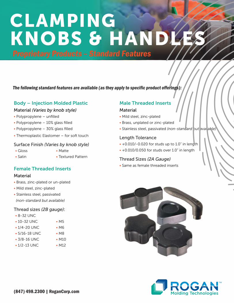
CLAMPING KNOBS & HANDLES
Plastic Dimensional Tolerances• Tolerances for the plastic portion of both
control knobs and clamping knobs range from
+/-0.005” to +/0.020” depending on the wall
thickness and length of the dimension as well
as the shrinkage rate of the material used
Shaft Hole Diameters• Round Shaft Hole: +0.0035” / -0.0000”
• Round Shaft Hole with Flat: +/-0.0035”
Push/Pull Specifications (Control Knobs)Maximum force required to securely fit a press-fit knob
onto a potentiometer shaft and the minimum force
required to remove the knob from the shaft.
• Plastic Shaft Hole
• Spring Clip Shaft Hole
• Knurled Type Shaft Hole
Custom shaft hole fit per customer specifications can be
provided for an additional tooling charge. Sample shaft
and tension requirements must be submitted to Rogan’s
customer support team – [email protected].
Torque SpecificationsMinimum rotational force required to break
item from molded plastic part:
Female thread inserts and male thread studs: • Below values are expressed in inch lbs.
Knob Diameter
8-32 10-32 1/4-20 5/16-16 3/8-16 1/3-13 M5 M6 M8 M10 M12
0.5”-1.25” 15 30 50 70 80 NA 30 50 70 80 NA
>1.25”-2.0” 20 40 60 70 90 100 40 60 70 90 100
Over 2.0” 25 50 65 70 90 100 50 65 70 90 100
Spring Clips (Control Knobs)• 0.125” diameter: 10 inch lbs
• 0.187” diameter: 15 inch lbs
• 0.250” diameter: 25 inch lbs
• 6mm diameter: 25 inch lbs
Set Screws (Control Knobs)• #4 (40 threads/inch): 4.75 inch lbs
• #6 (32 threads/inch): 8.75 inch lbs
• #8 (32 threads/inch): 18 inch lbs
• #10 (32 threads/inch): 32 inch lbs
Pull Out Specification (Clamping Knobs and Handles)Axial force required to remove a molded in insert or stud
head from a clamping knob or handle. All knobs: 100 lbs
minimum.
Marking Alignment and Set Screw Location Tolerance (Control Knobs)The following tolerances govern marking location for all
knobs and set screw location for pointer knobs:
• 0.37” to 0.86” knob diameter : +/- 7 degrees
• 0.87” to 2.50” knob diameter : +/- 5 degrees
(847) 498.2300 | RoganCorp.com
Proprietary Products – Standard Features
QUALITY STANDARDS
The following standard features are available (as they apply to specific product offerings):
Push: 15 lbs. Maximum Pull: 4 lbs. Minimum
Push: 20 lbs. Maximum Pull: 4 lbs. Minimum
Push: 20 lbs. Maximum Pull: 4 lbs. Minimum
Visual Defects (Control and Clamping Knobs)Show surfaces will be free of the following obvious
visual defects when observed with the unaided eye while
viewed for approximately 3 seconds at a distance of
approximately 18 inches in daylight (or fluorescent light of
80-120 ft candles), in the normal viewing plane:
• Dirt, grease, loose particulates and
foreign materials
• Splay
• Black specs and other imbedded contamination
• Burnt or discolored material
• Flow lines or knit lines
• Moderate-to-gross sinks (minor sink is allowed at the intersection of thick wall sections)
• Scratches and scuffs
Color Match (Control and Clamping Knobs)
• Color match is visually determined using color plaque standards. Color within lots and between lots may vary slightly due to
material variations.
Flash (Control and Clamping Knobs)
• Show surface flash: 0.010” max and
firmly attached
• Non-show surface flash: 0.020” max and
firmly attached
• Parting line mismatch: 0.010” max
Gate Protrusion• Size and visual appearance may vary
depending on material and color; however,
gate protrusion should not feel sharp to
the touch.
Marking (Control and Clamping Knobs)• Appearance: All marking graphics will be
complete and legible. Shade and density will
be consistent within a manufacturing lot but
slight variations between manufacturing lots
are allowable.
• Adhesion: Marking cannot be lifted from
surface by 3M Scotch™ cellophane tape.
Functional Defects (Control and Clamping Knobs)• Missing components
• Misassembled components
• Incomplete or damaged threads (male threads must conform to SAEJ1061-4.9 specification)
• Burrs or nicks on threads affecting function
• Short Shots
• Knit lines and voids affecting function
Notes• Rogan uses ANSI Z1.4 with a 2.5 AQL to determine quality acceptance.
• Unless agreed to in writing, Rogan reserves the
right to change specifications on the standard
elements of our products without notice.
• Customer requirements for more stringent
visual, dimensional, physical properties
must be specified in writing by customer and
approved by Rogan.
• Rogan’s Engineering team will work with customers
to optimize the insertion and removal force
between control knobs and potentiometer
shafts at the beginning of each program.
However, because each fit is dependent on
the dimensional consistency of the knob and
customer sourced potentiometers, and
because changes can be made to shaft size as
a result of potentiometer sourcing, customer
assumes ongoing responsibility for suitable fit.
Proprietary Products – Standard FeaturesQUALITY STANDARDS CONT.
(847) 498.2300 | RoganCorp.com
ISO 9001 Certified

(847) 498.2300 | RoganCorp.com
Parts are packaged to ensure quality is not compromised
during shipping. Depending on the need to protect parts,
various packaging methods are available:
• Blister packed on pads
• Bagged
• Protective covers over male threads
• Layer packed on pads
• Bulk packed
Carton labeling includes:• Customer Part Number • Quantity• Lot Number• Custom Formats Available
Proprietary Products – Standard Features
PACKAGING &LABELING
The following standard features are available (as they apply to specific product offerings):