Embed Size (px)
Citation preview
PROPS
Brochure Support with Telescopic and Push-pull PROPS
Support with telescopic and push-pull props
v2013/08en
Effective simplicity02
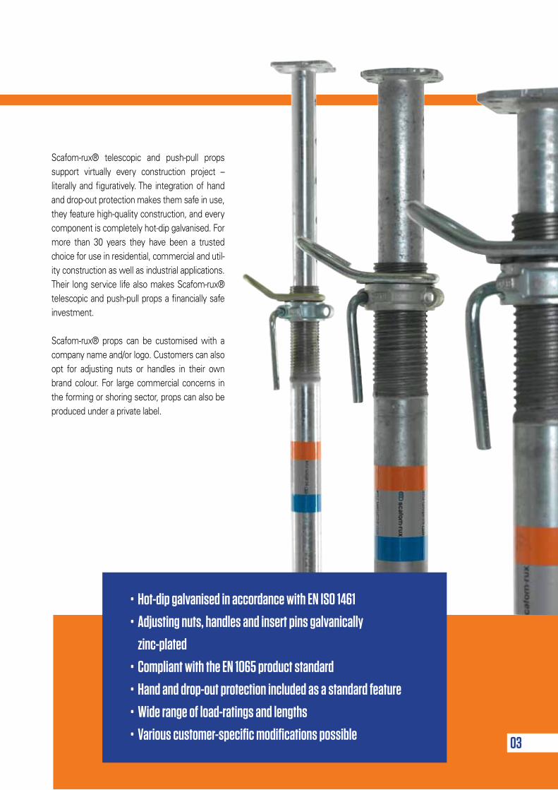
Scafom-rux® telescopic and push-pull props support virtually every construction project – literally and figuratively. The integration of hand and drop-out protection makes them safe in use, they feature high-quality construction, and every component is completely hot-dip galvanised. For more than 30 years they have been a trusted choice for use in residential, commercial and util-ity construction as well as industrial applications. Their long service life also makes Scafom-rux® telescopic and push-pull props a financially safe investment.
Scafom-rux® props can be customised with a company name and/or logo. Customers can also opt for adjusting nuts or handles in their own brand colour. For large commercial concerns in the forming or shoring sector, props can also be produced under a private label.
03
• Hot-dip galvanised in accordance with EN ISO 1461
• Adjusting nuts, handles and insert pins galvanically
zinc-plated
• Compliant with the EN 1065 product standard
• Hand and drop-out protection included as a standard feature
• Wide range of load-ratings and lengths
• Various customer-specific modifications possible
04
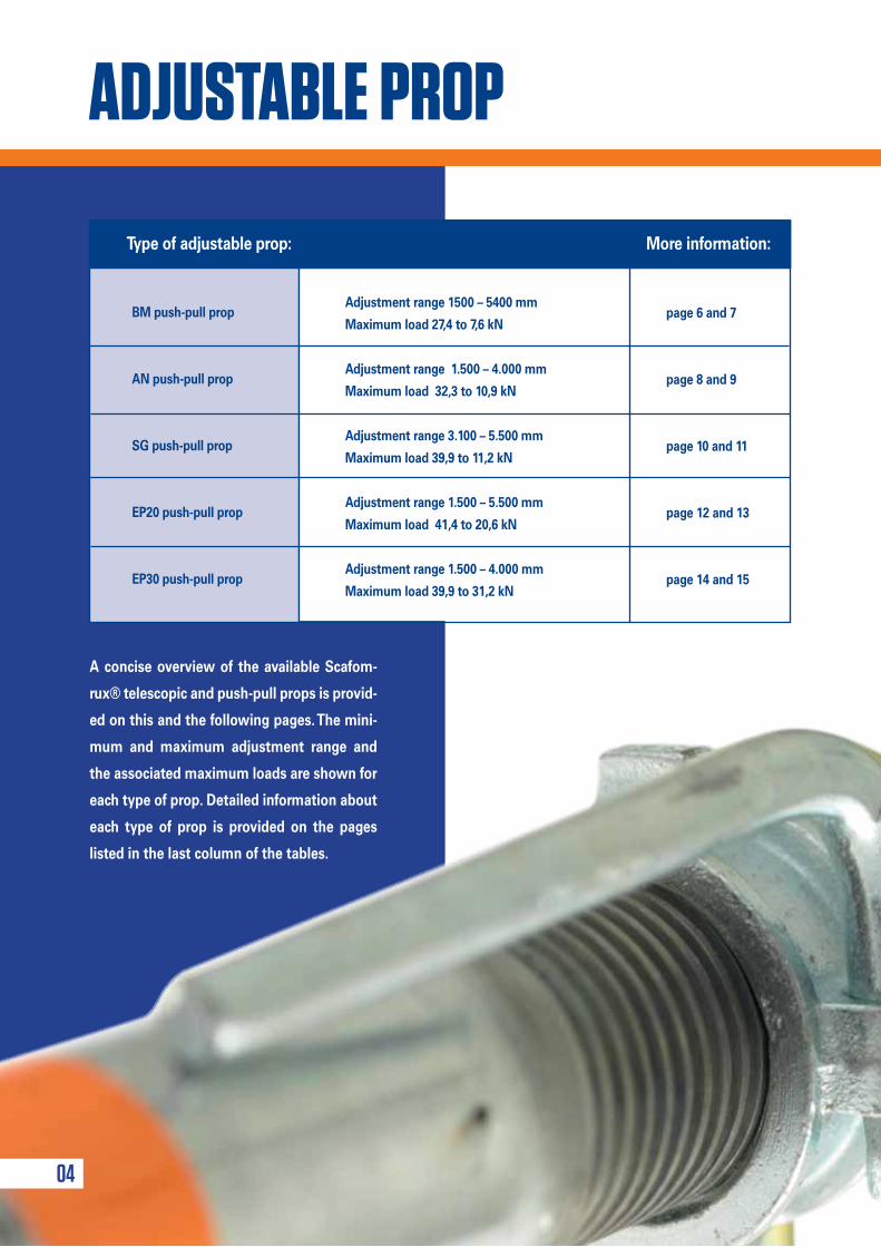
A concise overview of the available Scafom-
rux® telescopic and push-pull props is provid-
ed on this and the following pages. The mini-
mum and maximum adjustment range and
the associated maximum loads are shown for
each type of prop. Detailed information about
each type of prop is provided on the pages
listed in the last column of the tables.
Adjustment range 1500 – 5400 mm
Maximum load 27,4 to 7,6 kN
Adjustment range 1.500 – 4.000 mm
Maximum load 32,3 to 10,9 kN
Adjustment range 3.100 – 5.500 mm
Maximum load 39,9 to 11,2 kN
Adjustment range 1.500 – 5.500 mm
Maximum load 41,4 to 20,6 kN
Adjustment range 1.500 – 4.000 mm
Maximum load 39,9 to 31,2 kN
Type of adjustable prop: More information:
BM push-pull prop
AN push-pull prop
SG push-pull prop
EP20 push-pull prop
EP30 push-pull prop
page 6 and 7
page 8 and 9
page 10 and 11
page 12 and 13
page 14 and 15
ADJUSTABLE PROP
Quickly find the right solution
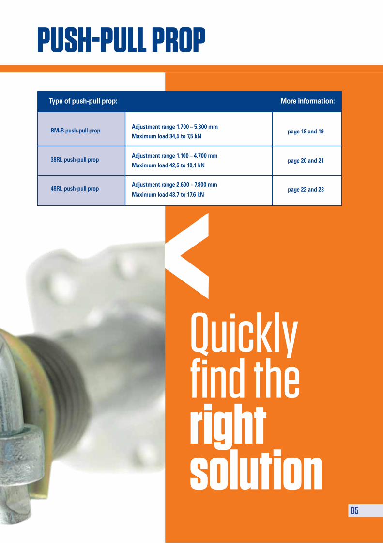
Adjustment range 1.700 – 5.300 mm
Maximum load 34,5 to 7,5 kN
Adjustment range 1.100 – 4.700 mm
Maximum load 42,5 to 10,1 kN
Adjustment range 2.600 – 7.800 mm
Maximum load 43,7 to 17,6 kN
Type of push-pull prop: More information:
BM-B push-pull prop
38RL push-pull prop
48RL push-pull prop
page 18 and 19
page 20 and 21
page 22 and 23
05
PUSh-PULL PROP
06
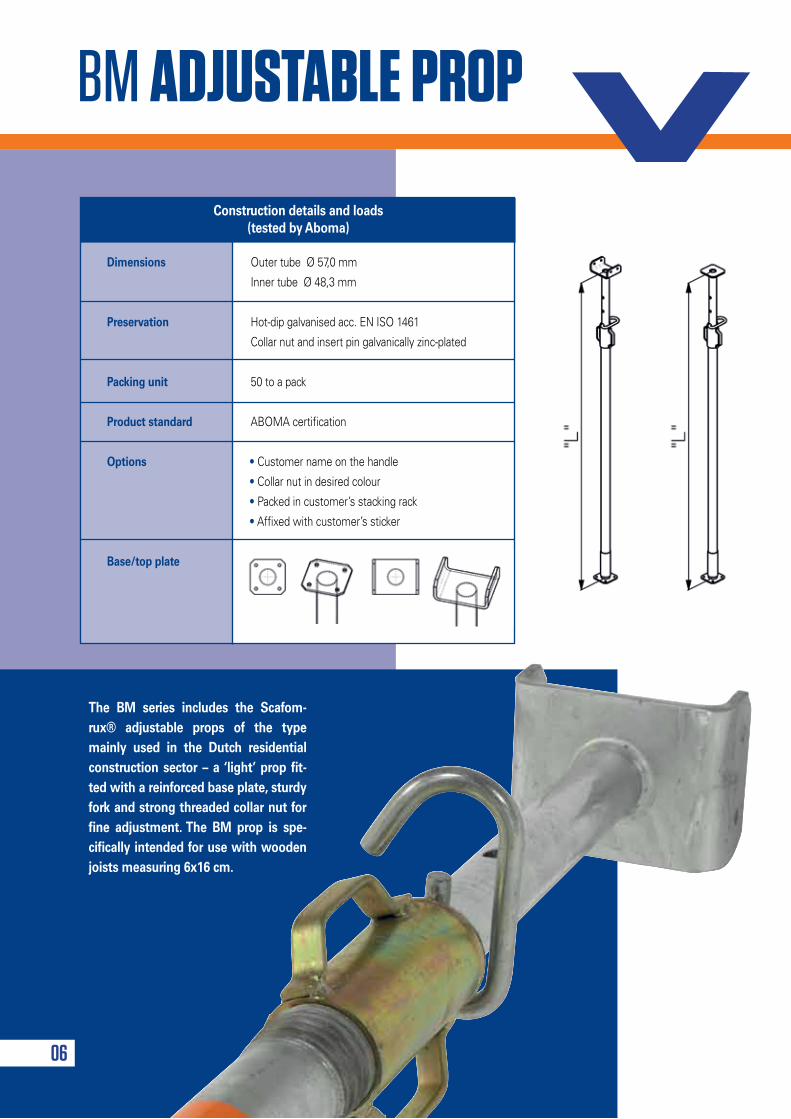
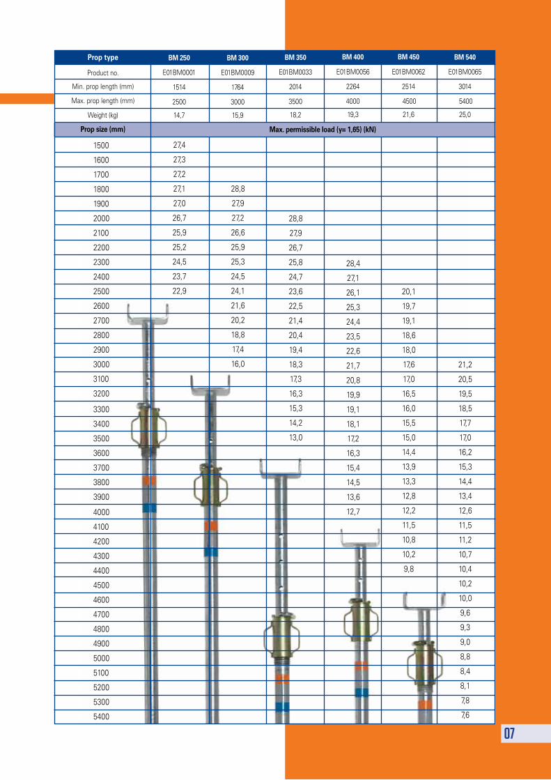
The BM series includes the Scafom-rux® adjustable props of the type mainly used in the Dutch residential construction sector – a ‘light’ prop fit-ted with a reinforced base plate, sturdy fork and strong threaded collar nut for fine adjustment. The BM prop is spe-cifically intended for use with wooden joists measuring 6x16 cm.
BM ADJUSTABLE PROP
Dimensions Outer tube Ø 57,0 mm
Inner tube Ø 48,3 mm
Preservation Hot-dip galvanised acc. EN ISO 1461
Collar nut and insert pin galvanically zinc-plated
Packing unit 50 to a pack
Product standard ABOMA certification
Options • Customer name on the handle
• Collar nut in desired colour
• Packed in customer’s stacking rack
• Affixed with customer’s sticker
Base/top plate
Construction details and loads(tested by Aboma)
07
1500
1600
1700
1800
1900
2000
2100
2200
2300
2400
2500
2600
2700
2800
2900
3000
3100
3200
3300
3400
3500
3600
3700
3800
3900
4000
4100
4200
4300
4400
4500
4600
4700
4800
4900
5000
5100
5200
5300
5400
27,4
27,3
27,2
27,1
27,0
26,7
25,9
25,2
24,5
23,7
22,9
28,8
27,9
27,2
26,6
25,9
25,3
24,5
24,1
21,6
20,2
18,8
17,4
16,0
28,8
27,9
26,7
25,8
24,7
23,6
22,5
21,4
20,4
19,4
18,3
17,3
16,3
15,3
14,2
13,0
28,4
27,1
26,1
25,3
24,4
23,5
22,6
21,7
20,8
19,9
19,1
18,1
17,2
16,3
15,4
14,5
13,6
12,7
20,1
19,7
19,1
18,6
18,0
17,6
17,0
16,5
16,0
15,5
15,0
14,4
13,9
13,3
12,8
12,2
11,5
10,8
10,2
9,8
21,2
20,5
19,5
18,5
17,7
17,0
16,2
15,3
14,4
13,4
12,6
11,5
11,2
10,7
10,4
10,2
10,0
9,6
9,3
9,0
8,8
8,4
8,1
7,8
7,6
BM 250
E01BM0001
1514
2500
14,7
BM 300
E01BM0009
1764
3000
15,9
BM 350
E01BM0033
2014
3500
18,2
BM 400
E01BM0056
2264
4000
19,3
BM 450
E01BM0062
2514
4500
21,6
BM 540
E01BM0065
3014
5400
25,0
Prop type
Product no.
Min. prop length (mm)
Max. prop length (mm)
Weight (kg)
Prop size (mm) Max. permissible load (y= 1,65) (kN)
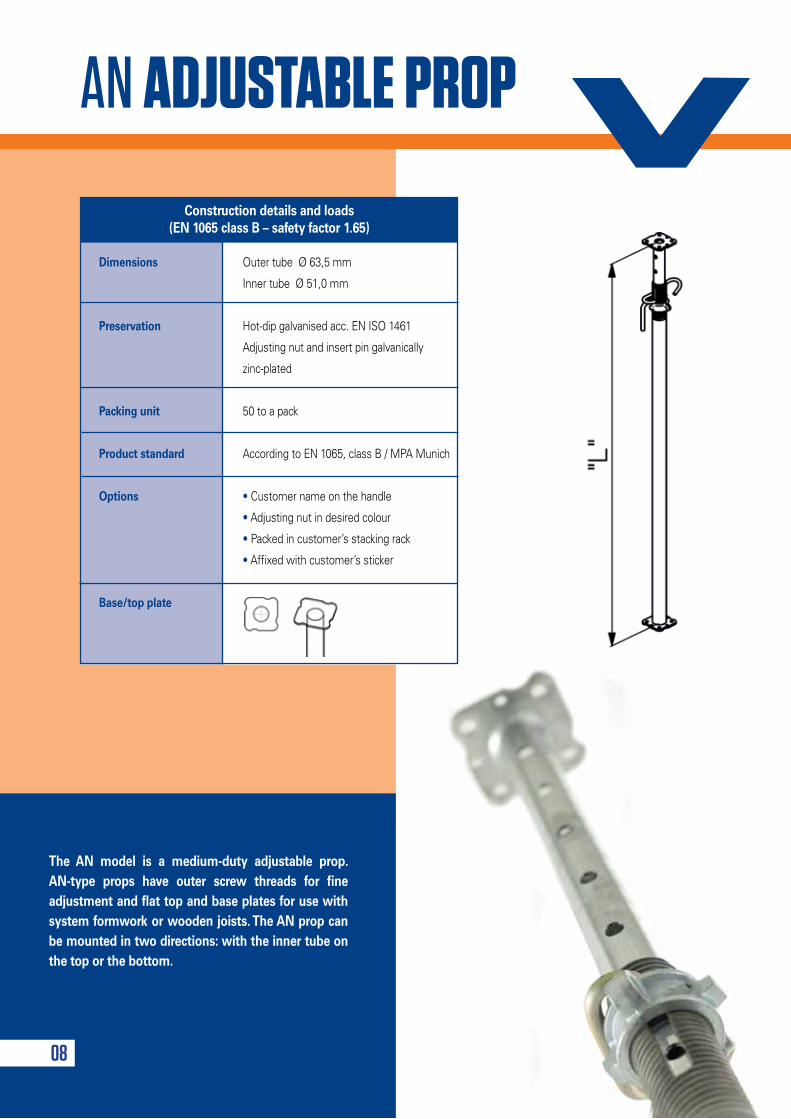
AN ADJUSTABLE PROP
The AN model is a medium-duty adjustable prop. AN-type props have outer screw threads for fine adjustment and flat top and base plates for use with system formwork or wooden joists. The AN prop can be mounted in two directions: with the inner tube on the top or the bottom.
08
Dimensions Outer tube Ø 63,5 mm
Inner tube Ø 51,0 mm
Preservation Hot-dip galvanised acc. EN ISO 1461
Adjusting nut and insert pin galvanically
zinc-plated
Packing unit 50 to a pack
Product standard According to EN 1065, class B / MPA Munich
Options • Customer name on the handle
• Adjusting nut in desired colour
• Packed in customer’s stacking rack
• Affixed with customer’s sticker
Base/top plate
Construction details and loads (EN 1065 class B – safety factor 1.65)
09
Prop type
Classification acc. EN1065
Product no.
Min. prop length (mm)
Max. prop length (mm)
Weight (kg)
Prop size (mm)
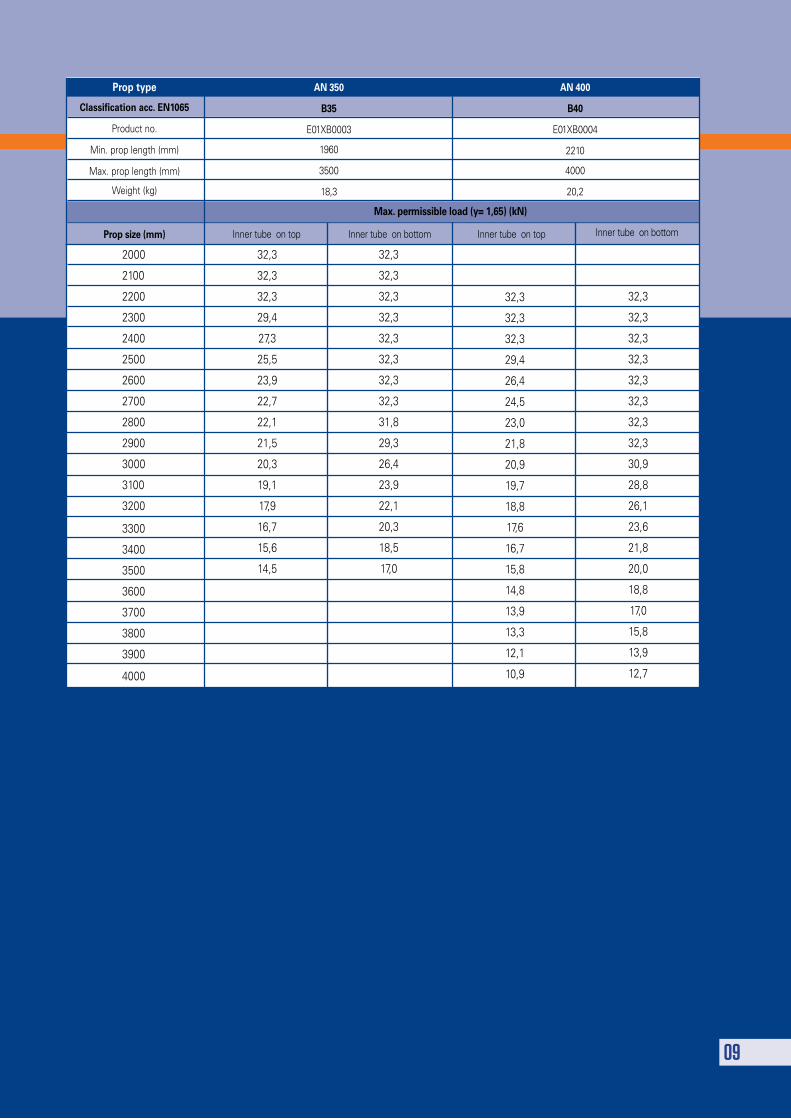
AN 350
B35
E01XB0003
1960
3500
18,3
AN 400
B40
E01XB0004
2210
4000
20,2
Max. permissible load (y= 1,65) (kN)
Inner tube on top Inner tube on bottom Inner tube on top Inner tube on bottom
32,3
32,3
32,3
29,4
27,3
25,5
23,9
22,7
22,1
21,5
20,3
19,1
17,9
16,7
15,6
14,5
32,3
32,3
32,3
29,4
26,4
24,5
23,0
21,8
20,9
19,7
18,8
17,6
16,7
15,8
14,8
13,9
13,3
12,1
10,9
32,3
32,3
32,3
32,3
32,3
32,3
32,3
32,3
30,9
28,8
26,1
23,6
21,8
20,0
18,8
17,0
15,8
13,9
12,7
32,3
32,3
32,3
32,3
32,3
32,3
32,3
32,3
31,8
29,3
26,4
23,9
22,1
20,3
18,5
17,0
2000
2100
2200
2300
2400
2500
2600
2700
2800
2900
3000
3100
3200
3300
3400
3500
3600
3700
3800
3900
4000
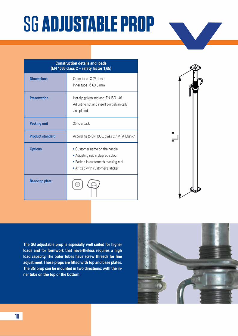
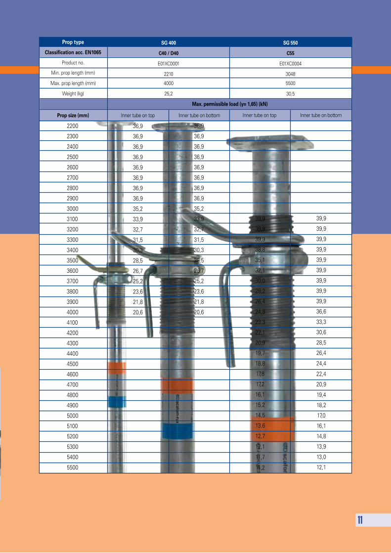
The SG adjustable prop is especially well suited for higher loads and for formwork that nevertheless requires a high load capacity. The outer tubes have screw threads for fine adjustment. These props are fitted with top and base plates. The SG prop can be mounted in two directions: with the in-ner tube on the top or the bottom.
SG ADJUSTABLE PROP
10
Dimensions Outer tube Ø 76,1 mm
Inner tube Ø 63,5 mm
Preservation Hot-dip galvanised acc. EN ISO 1461
Adjusting nut and insert pin galvanically
zinc-plated
Packing unit 35 to a pack
Product standard According to EN 1065, class C / MPA Munich
Options • Customer name on the handle
• Adjusting nut in desired colour
• Packed in customer’s stacking rack
• Affixed with customer’s sticker
Base/top plate
Construction details and loads (EN 1065 class C – safety factor 1,65)
11
2200
2300
2400
2500
2600
2700
2800
2900
3000
3100
3200
3300
3400
3500
3600
3700
3800
3900
4000
4100
4200
4300
4400
4500
4600
4700
4800
4900
5000
5100
5200
5300
5400
5500
36,9
36,9
36,9
36,9
36,9
36,9
36,9
36,9
35,2
33,9
32,7
31,5
30,3
28,5
26,7
25,2
23,6
21,8
20,6
Max. permissible load (y= 1,65) (kN)
39,9
39,9
39,9
38,8
35,1
32,1
30,0
28,2
26,4
24,8
23,3
22,1
20,9
19,7
18,8
17,8
17,2
16,1
15,2
14,5
13,6
12,7
12,1
11,7
11,2
39,9
39,9
39,9
39,9
39,9
39,9
39,9
39,9
39,9
36,6
33,3
30,6
28,5
26,4
24,4
22,4
20,9
19,4
18,2
17,0
16,1
14,8
13,9
13,0
12,1
Prop type
Classification acc. EN1065
Product no.
Min. prop length (mm)
Max. prop length (mm)
Weight (kg)
Prop size (mm)
SG 400
C40 / D40
E01XC0001
2210
4000
25,2
SG 550
C55
E01XC0004
3048
5500
30,5
Inner tube on top Inner tube on bottom Inner tube on top Inner tube on bottom
36,9
36,9
36,9
36,9
36,9
36,9
36,9
36,9
35,2
33,9
32,7
31,5
30,3
28,5
26,7
25,2
23,6
21,8
20,6
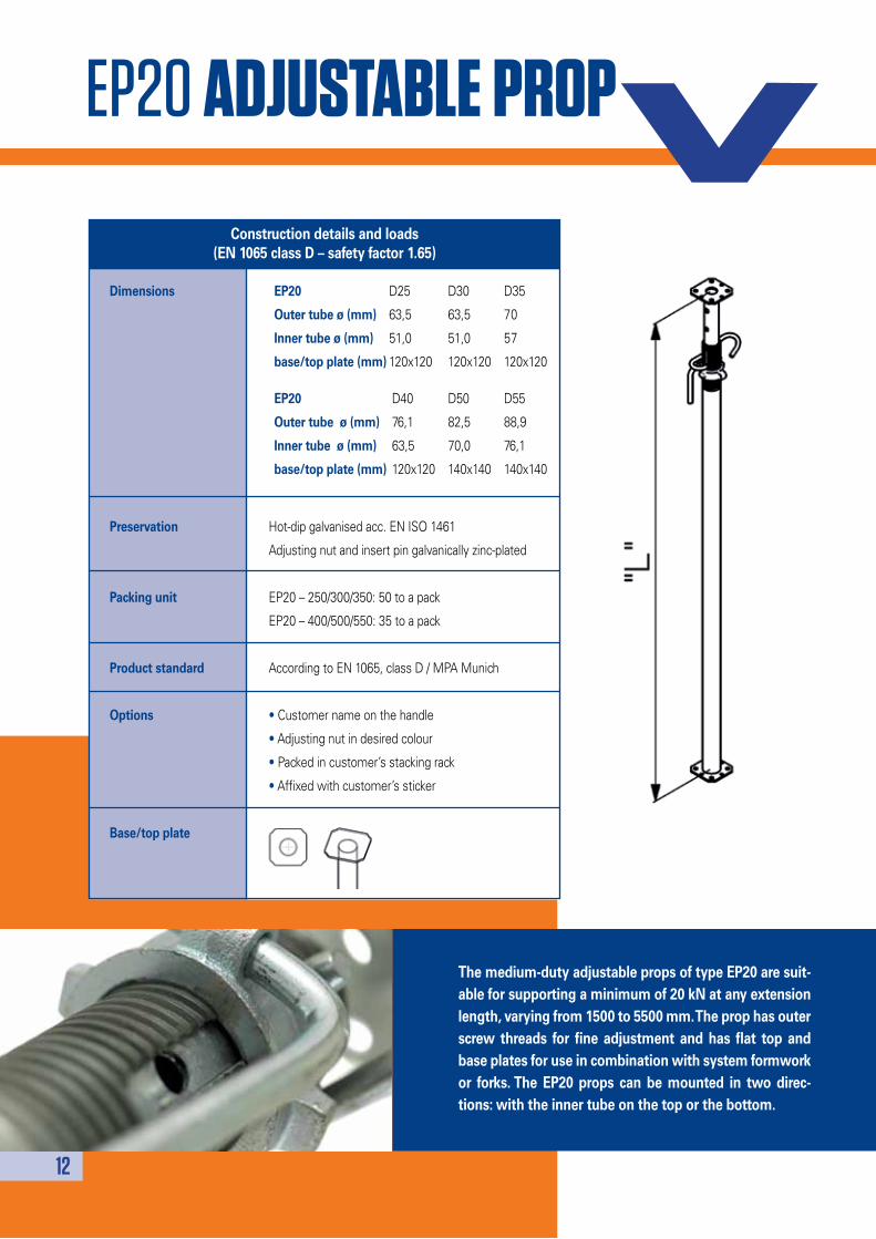
EP20 ADJUSTABLE PROP
12
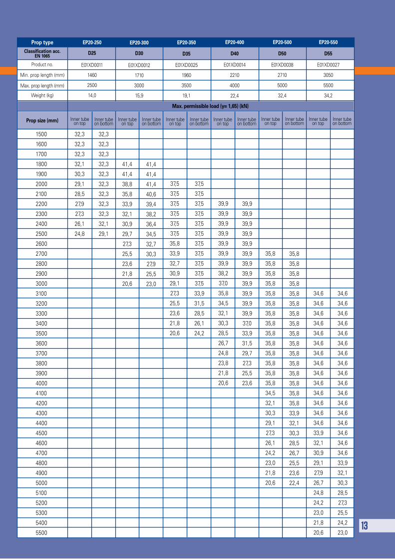
The medium-duty adjustable props of type EP20 are suit-able for supporting a minimum of 20 kN at any extension length, varying from 1500 to 5500 mm. The prop has outer screw threads for fine adjustment and has flat top and base plates for use in combination with system formwork or forks. The EP20 props can be mounted in two direc-tions: with the inner tube on the top or the bottom.
Dimensions
Preservation Hot-dip galvanised acc. EN ISO 1461
Adjusting nut and insert pin galvanically zinc-plated
Packing unit EP20 – 250/300/350: 50 to a pack
EP20 – 400/500/550: 35 to a pack
Product standard According to EN 1065, class D / MPA Munich
Options • Customer name on the handle
• Adjusting nut in desired colour
• Packed in customer’s stacking rack
• Affixed with customer’s sticker
Base/top plate
Construction details and loads(EN 1065 class D – safety factor 1.65)
EP20 D25 D30 D35
Outer tube ø (mm) 63,5 63,5 70
Inner tube ø (mm) 51,0 51,0 57
base/top plate (mm) 120x120 120x120 120x120
EP20 D40 D50 D55
Outer tube ø (mm) 76,1 82,5 88,9
Inner tube ø (mm) 63,5 70,0 76,1
base/top plate (mm) 120x120 140x140 140x140
13
EP20-250
D25
E01XD0011
1460
2500
14,0
Prop type
Classification acc. EN 1065
Product no.
Min. prop length (mm)
Max. prop length (mm)
Weight (kg)
Prop size (mm)
EP20-300
D30
E01XD0012
1710
3000
15,9
EP20-350
D35
E01XD0025
1960
3500
19,1
EP20-400
D40
E01XD0014
2210
4000
22,4
EP20-500
D50
E01XD0038
2710
5000
32,4
1500
1600
1700
1800
1900
2000
2100
2200
2300
2400
2500
2600
2700
2800
2900
3000
3100
3200
3300
3400
3500
3600
3700
3800
3900
4000
4100
4200
4300
4400
4500
4600
4700
4800
4900
5000
5100
5200
5300
5400
5500
32,3
32,3
32,3
32,1
30,3
29,1
28,5
27,9
27,3
26,1
24,8
32,3
32,3
32,3
32,3
32,3
32,3
32,3
32,3
32,3
32,1
29,1
37,5
37,5
37,5
37,5
37,5
37,5
37,5
37,5
37,5
37,5
37,5
33,9
31,5
28,5
26,1
24,2
39,9
39,9
39,9
39,9
39,9
39,9
39,9
38,2
37,0
35,8
34,5
32,1
30,3
28,5
26,7
24,8
23,8
21,8
20,6
39,9
39,9
39,9
39,9
39,9
39,9
39,9
39,9
39,9
39,9
39,9
39,9
37,0
33,9
31,5
29,7
27,3
25,5
23,6
35,8
35,8
35,8
35,8
35,8
35,8
35,8
35,8
35,8
35,8
35,8
35,8
35,8
35,8
34,5
32,1
30,3
29,1
27,3
26,1
24,2
23,0
21,8
20,6
35,8
35,8
35,8
35,8
35,8
35,8
35,8
35,8
35,8
35,8
35,8
35,8
35,8
35,8
35,8
35,8
33,9
32,1
30,3
28,5
26,7
25,5
23,6
22,4
34,6
34,6
34,6
34,6
34,6
34,6
34,6
34,6
34,6
34,6
34,6
34,6
34,6
34,6
33,9
32,1
30,9
29,1
27,9
26,7
24,8
24,2
23,0
21,8
20,6
34,6
34,6
34,6
34,6
34,6
34,6
34,6
34,6
34,6
34,6
34,6
34,6
34,6
34,6
34,6
34,6
34,6
33,9
32,1
30,3
28,5
27,3
25,5
24,2
23,0
41,4
41,4
38,8
35,8
33,9
32,1
30,9
29,7
27,3
25,5
23,6
21,8
20,6
41,4
41,4
41,4
40,6
39,4
38,2
36,4
34,5
32,7
30,3
27,9
25,5
23,0
37,5
37,5
37,5
37,5
37,5
37,5
35,8
33,9
32,7
30,9
29,1
27,3
25,5
23,6
21,8
20,6
Max. permissible load (y= 1,65) (kN)
Inner tube on top
Inner tube on bottom
Inner tube on top
Inner tube on bottom
Inner tube on top
Inner tube on bottom
Inner tube on top
Inner tube on bottom
Inner tube on top
Inner tube on bottom
Inner tube on top
Inner tube on bottom
EP20-550
D55
E01XD0027
3050
5500
34,2
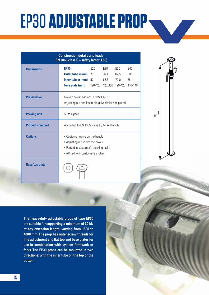
EP30 ADJUSTABLE PROP
14
The heavy-duty adjustable props of type EP30 are suitable for supporting a minimum of 30 kN at any extension length, varying from 1500 to 4000 mm. The prop has outer screw threads for fine adjustment and flat top and base plates for use in combination with system formwork or forks. The EP30 props can be mounted in two directions: with the inner tube on the top or the bottom.
Dimensions
Preservation Hot-dip galvanised acc. EN ISO 1461
Adjusting nut and insert pin galvanically zinc-plated
Packing unit 50 to a pack
Product standard According to EN 1065, class E / MPA Munich
Options • Customer name on the handle
• Adjusting nut in desired colour
• Packed in customer’s stacking rack
• Affixed with customer’s sticker
Base/top plate
Construction details and loads (EN 1065 class E – safety factor 1.65)
EP30 E25 E30 E35 E40
Outer tube ø (mm) 70 76,1 82,5 88,9
Inner tube ø (mm) 57 63,5 70,0 76,1
base plate (mm) 120x120 120x120 120x120 140x140
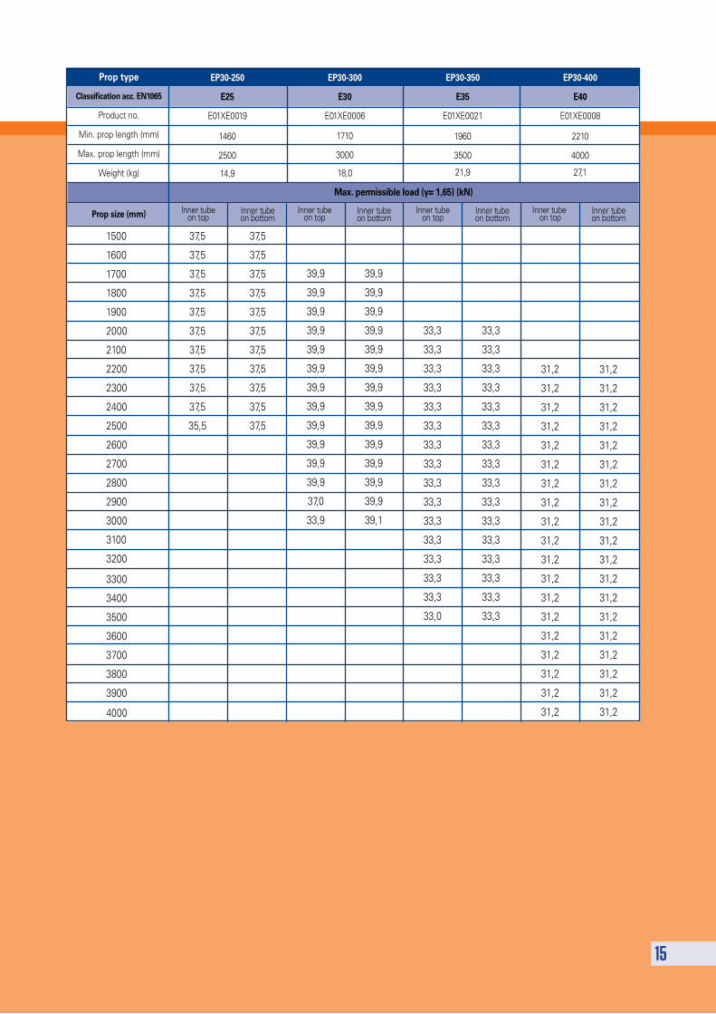
15
Max. permissible load (y= 1,65) (kN)
1500
1600
1700
1800
1900
2000
2100
2200
2300
2400
2500
2600
2700
2800
2900
3000
3100
3200
3300
3400
3500
3600
3700
3800
3900
4000
37,5
37,5
37,5
37,5
37,5
37,5
37,5
37,5
37,5
37,5
35,5
39,9
39,9
39,9
39,9
39,9
39,9
39,9
39,9
39,9
39,9
39,9
39,9
37,0
33,9
33,3
33,3
33,3
33,3
33,3
33,3
33,3
33,3
33,3
33,3
33,3
33,3
33,3
33,3
33,3
33,0
37,5
37,5
37,5
37,5
37,5
37,5
37,5
37,5
37,5
37,5
37,5
39,9
39,9
39,9
39,9
39,9
39,9
39,9
39,9
39,9
39,9
39,9
39,9
39,9
39,1
33,3
33,3
33,3
33,3
33,3
33,3
33,3
33,3
33,3
33,3
33,3
33,3
33,3
33,3
33,3
33,3
31,2
31,2
31,2
31,2
31,2
31,2
31,2
31,2
31,2
31,2
31,2
31,2
31,2
31,2
31,2
31,2
31,2
31,2
31,2
31,2
31,2
31,2
31,2
31,2
31,2
31,2
31,2
31,2
31,2
31,2
31,2
31,2
31,2
31,2
31,2
31,2
31,2
31,2
EP30-250
E25
E01XE0019
1460
2500
14,9
Prop type
Classification acc. EN1065
Product no.
Min. prop length (mm)
Max. prop length (mm)
Weight (kg)
Prop size (mm)
EP30-300
E30
E01XE0006
1710
3000
18,0
EP30-350
E35
E01XE0021
1960
3500
21,9
EP30-400
E40
E01XE0008
2210
4000
27,1
Inner tube on top
Inner tube on bottom
Inner tube on top
Inner tube on bottom
Inner tube on top
Inner tube on bottom
Inner tube on top
Inner tube on bottom
16
17
18
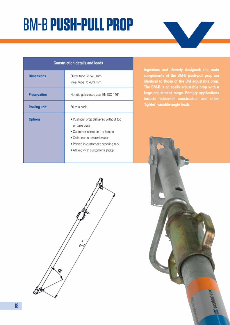
BM-B PUSh-PULL PROP
Ingenious and cleverly designed: the main components of the BM-B push-pull prop are identical to those of the BM adjustable prop. The BM-B is an easily adjustable prop with a large adjustment range. Primary applications include residential construction and other ‘lighter’ variable-angle loads.
Dimensions Outer tube Ø 57,0 mm
Inner tube Ø 48,3 mm
Preservation Hot-dip galvanised acc. EN ISO 1461
Packing unit 50 to a pack
Options • Push-pull prop delivered without top
or base plate
• Customer name on the handle
• Collar nut in desired colour
• Packed in customer’s stacking rack
• Affixed with customer’s sticker
Construction details and loads
19
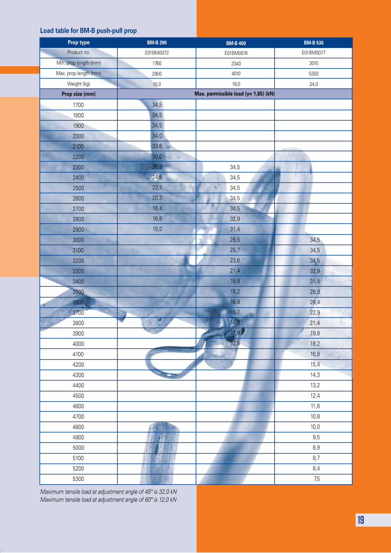
Maximum tensile load at adjustment angle of 45º is 32,0 kNMaximum tensile load at adjustment angle of 60º is 12,0 kN
Load table for BM-B push-pull prop
1700
1800
1900
2000
2100
2200
2300
2400
2500
2600
2700
2800
2900
3000
3100
3200
3300
3400
3500
3600
3700
3800
3900
4000
4100
4200
4300
4400
4500
4600
4700
4800
4900
5000
5100
5200
5300
34,5
34,5
34,5
34,0
33,6
30,0
26,8
24,5
22,1
20,3
18,4
16,6
15,0
34,5
34,5
34,5
32,9
31,4
28,9
26,4
22,9
21,4
19,8
18,2
16,8
15,4
14,3
13,2
12,4
11,6
10,8
10,0
9,5
8,9
8,7
8,4
7,5
34,5
34,5
34,5
34,5
34,5
32,9
31,4
28,5
25,7
23,6
21,4
19,8
18,2
16,9
15,7
14,8
13,9
12,5
Prop type
Product no.
Min. prop length (mm)
Max. prop length (mm)
Weight (kg)
Prop size (mm)
BM-B 290
E01BM0072
1760
2900
15,0
BM-B 400
E01BM0074
2340
4010
19,0
BM-B 530
E01BM0077
3010
5350
24,0
Max. permissible load (y= 1,65) (kN)
38RL PUSh-PULL PROP
20
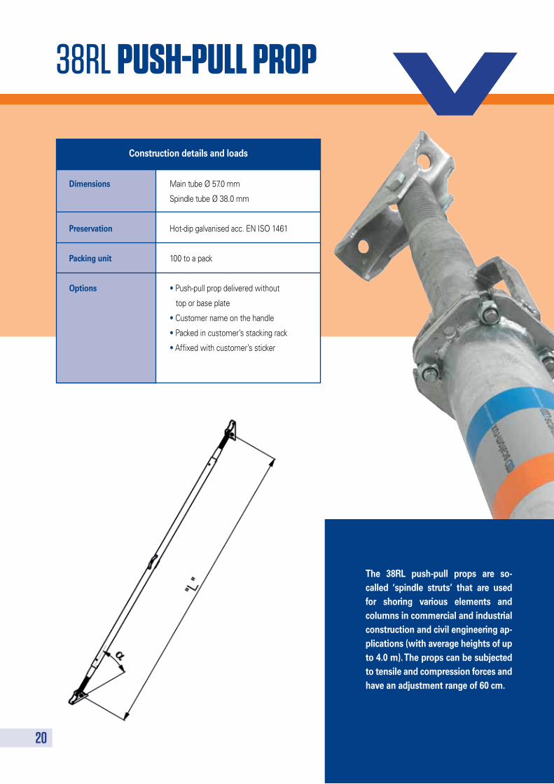
The 38RL push-pull props are so-called ‘spindle struts’ that are used for shoring various elements and columns in commercial and industrial construction and civil engineering ap-plications (with average heights of up to 4.0 m). The props can be subjected to tensile and compression forces and have an adjustment range of 60 cm.
Dimensions Main tube Ø 57.0 mm
Spindle tube Ø 38.0 mm
Preservation Hot-dip galvanised acc. EN ISO 1461
Packing unit 100 to a pack
Options • Push-pull prop delivered without
top or base plate
• Customer name on the handle
• Packed in customer’s stacking rack
• Affixed with customer’s sticker
Construction details and loads
21
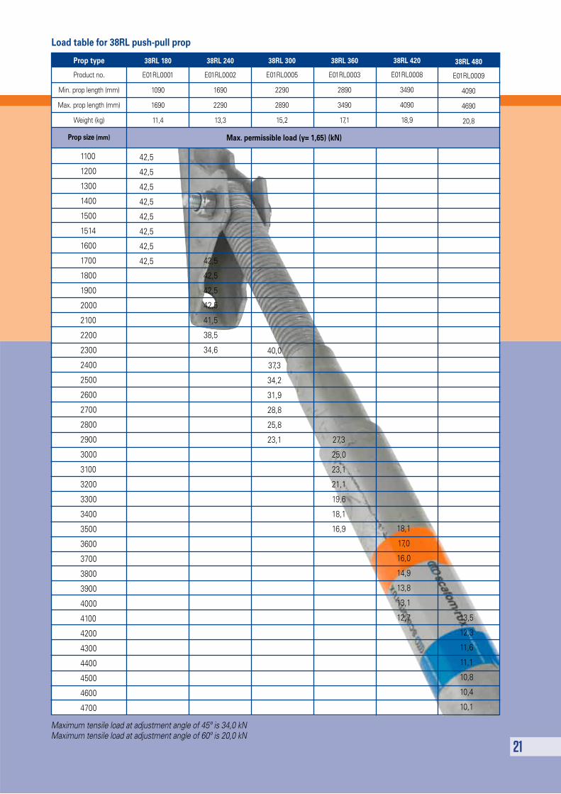
Maximum tensile load at adjustment angle of 45º is 34,0 kNMaximum tensile load at adjustment angle of 60º is 20,0 kN
Load table for 38RL push-pull prop
1100
1200
1300
1400
1500
1514
1600
1700
1800
1900
2000
2100
2200
2300
2400
2500
2600
2700
2800
2900
3000
3100
3200
3300
3400
3500
3600
3700
3800
3900
4000
4100
4200
4300
4400
4500
4600
4700
42,5
42,5
42,5
42,5
42,5
42,5
42,5
42,5
40,0
37,3
34,2
31,9
28,8
25,8
23,1 27,3
25,0
23,1
21,1
19,6
18,1
16,9
42,5
42,5
42,5
42,5
41,5
38,5
34,6
18,1
17,0
16,0
14,9
13,8
13,1
12,7 13,5
12,3
11,6
11,1
10,8
10,4
10,1
Prop type
Product no.
Min. prop length (mm)
Max. prop length (mm)
Weight (kg)
Prop size (mm)
38RL 180
E01RL0001
1090
1690
11,4
38RL 240
E01RL0002
1690
2290
13,3
38RL 300
E01RL0005
2290
2890
15,2
38RL 360
E01RL0003
2890
3490
17,1
38RL 420
E01RL0008
3490
4090
18,9
38RL 480
E01RL0009
4090
4690
20,8
Max. permissible load (y= 1,65) (kN)
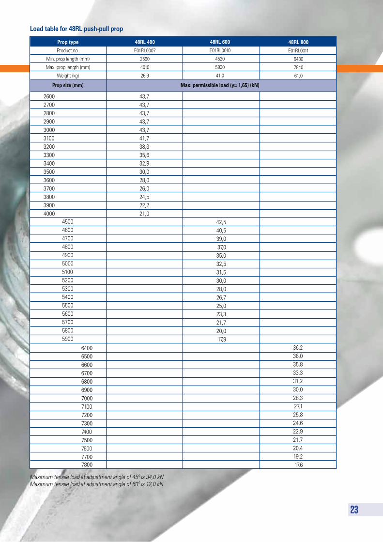
48RL PUSh-PULL PROP
22
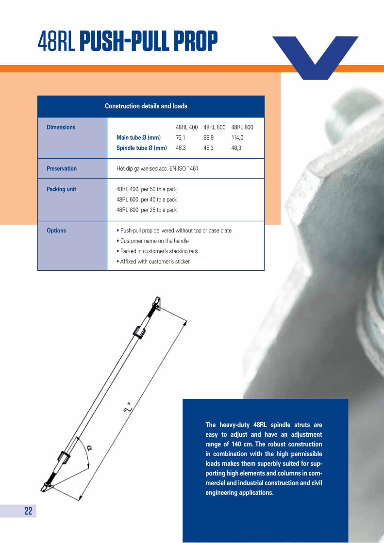
The heavy-duty 48RL spindle struts are easy to adjust and have an adjustment range of 140 cm. The robust construction in combination with the high permissible loads makes them superbly suited for sup-porting high elements and columns in com-mercial and industrial construction and civil engineering applications.
Dimensions 48RL 400 48RL 600 48RL 800
Main tube Ø (mm) 76,1 88,9 114,0
Spindle tube Ø (mm) 48,3 48,3 48,3
Preservation Hot-dip galvanised acc. EN ISO 1461
Packing unit 48RL 400: per 50 to a pack
48RL 600: per 40 to a pack
48RL 800: per 25 to a pack
Options • Push-pull prop delivered without top or base plate
• Customer name on the handle
• Packed in customer’s stacking rack
• Affixed with customer’s sticker
Construction details and loads
23
Maximum tensile load at adjustment angle of 45º is 34,0 kNMaximum tensile load at adjustment angle of 60º is 12,0 kN
Load table for 48RL push-pull prop
450046004700480049005000510052005300540055005600570058005900
43,743,743,743,743,741,738,335,632,930,028,026,024,522,221,0
36,236,035,833,331,230,028,327,125,824,622,921,720,419,217,6
42,540,539,037,035,032,531,530,028,026,725,023,321,720,017,9
Prop type
Product no.
Min. prop length (mm)
Max. prop length (mm)
Weight (kg)
Prop size (mm)
48RL 400
E01RL0007
2590
4010
26,9
48RL 600
E01RL0010
4520
5930
41,0
48RL 800
E01RL0011
6430
7840
61,0
260027002800290030003100320033003400350036003700380039004000
640065006600670068006900700071007200730074007500760077007800
Max. permissible load (y= 1,65) (kN)

v2013/08en
v2013/08en


![RUX-SUPER 65 - Home - Scafom-rux-deutschland [de] GmbH · Phone +49 2331 4709-0 · Fax +49 2331 4709-202 · Mail rux@rux.de Rapid-Erection Scaffolding RUX-SUPER 65 3 Instructions for](https://img.pdfslide.net/doc/110x75/5add1f2a7f8b9a9d4d8cbb0f/rux-super-65-home-scafom-rux-deutschland-de-gmbh-phone-49-2331-4709-0-fax.jpg)


![SUPER 100 - Scafom-rux-deutschland [de] · PDF fileAufbau- und Verwendungsanleitung SUPER 100 Stand 26.11.2013 Seite 1 Aufbau- und Verwendungsanleitung Gerüstsystem: BERA-RUX Schnellbaugerüst](https://img.pdfslide.net/doc/110x75/5a79f5fc7f8b9adf778b7be8/super-100-scafom-rux-deutschland-de-und-verwendungsanleitung-super-100-stand.jpg)