Embed Size (px)
Citation preview
350 East Plumeria DriveSan Jose, CA 95134USA
June 2013202-11223-01
ProSAFE Single Band 802.11n Wireless Access Point WN203Reference Manual
2
ProSAFE Single Band 802.11n Wireless Access Point WN203
SupportThank you for selecting NETGEAR products. After installing your device, locate the serial number on the label of your product and use it to register your product at https://my.netgear.com. You must register your product before you can use NETGEAR telephone support. NETGEAR recommends registering your product through the NETGEAR website. For product updates and web support, visit http://support.netgear.com.Phone (US & Canada only): 1-888-NETGEAR.Phone (Other Countries): Check the list of phone numbers at http://support.netgear.com/general/contact/default.aspx.
TrademarksNETGEAR, the NETGEAR logo, and Connect with Innovation are trademarks and/or registered trademarks of NETGEAR, Inc. and/or its subsidiaries in the United States and/or other countries. Information is subject to change without notice. © NETGEAR, Inc. All rights reserved.
Revision History
Publication Part Number
Publish Date Comments
202-11230-01 June 2013 First publication
Contents
Chapter 1 IntroductionAbout the ProSAFE Single Band 802.11n Wireless Access Point WN203 .7What Is in the Box? . . . . . . . . . . . . . . . . . . . . . . . . . . . . . . . . . . . . . . . . . . . 7System Requirements . . . . . . . . . . . . . . . . . . . . . . . . . . . . . . . . . . . . . . . . . 8Key Features and Standards . . . . . . . . . . . . . . . . . . . . . . . . . . . . . . . . . . . . 8
Supported Standards and Conventions . . . . . . . . . . . . . . . . . . . . . . . . . .8Key Features . . . . . . . . . . . . . . . . . . . . . . . . . . . . . . . . . . . . . . . . . . . . . . 9802.11b/g/n Standards–Based Wireless Networking . . . . . . . . . . . . . . .10Autosensing Ethernet Connections with Auto Uplink . . . . . . . . . . . . . . .11
Hardware Description . . . . . . . . . . . . . . . . . . . . . . . . . . . . . . . . . . . . . . . . . 11Front Panel . . . . . . . . . . . . . . . . . . . . . . . . . . . . . . . . . . . . . . . . . . . . . . . 11Back Panel . . . . . . . . . . . . . . . . . . . . . . . . . . . . . . . . . . . . . . . . . . . . . . . 12Bottom Panel with Product Label and Reset to Factory Defaults Button13
Chapter 2 Installation and Basic ConfigurationWhat You Need Before You Begin . . . . . . . . . . . . . . . . . . . . . . . . . . . . . . .15
Wireless Equipment Placement and Range Guidelines . . . . . . . . . . . . .15Ethernet Cabling Requirements . . . . . . . . . . . . . . . . . . . . . . . . . . . . . . .16LAN Configuration Requirements. . . . . . . . . . . . . . . . . . . . . . . . . . . . . .16Hardware Requirements for Computers on Your LAN . . . . . . . . . . . . . .16Requirements for Entering IP Addresses . . . . . . . . . . . . . . . . . . . . . . . .16
Install and Configure the Wireless Access Point . . . . . . . . . . . . . . . . . . . .16Connect the Wireless Access Point to a Computer . . . . . . . . . . . . . . . .17Log In to the Wireless Access Point . . . . . . . . . . . . . . . . . . . . . . . . . . . .18Configure Basic General System Settings and Time Settings . . . . . . . .20Configure the IP Settings . . . . . . . . . . . . . . . . . . . . . . . . . . . . . . . . . . . . 22Configure the Optional DHCP Server. . . . . . . . . . . . . . . . . . . . . . . . . . .23Configure the Basic Wireless Settings . . . . . . . . . . . . . . . . . . . . . . . . . .25
Test Basic Wireless Connectivity . . . . . . . . . . . . . . . . . . . . . . . . . . . . . . . .28
Chapter 3 Wireless Configuration and SecurityBefore You Configure Wireless Security . . . . . . . . . . . . . . . . . . . . . . . . . .31Wireless Data Security Options . . . . . . . . . . . . . . . . . . . . . . . . . . . . . . . . .31Security Profiles . . . . . . . . . . . . . . . . . . . . . . . . . . . . . . . . . . . . . . . . . . . . . 33
Security Profile Concepts . . . . . . . . . . . . . . . . . . . . . . . . . . . . . . . . . . . . 34Write Down Your Wireless Network Settings . . . . . . . . . . . . . . . . . . . . .35Configure and Enable Security Profiles . . . . . . . . . . . . . . . . . . . . . . . . .36
Configure RADIUS Server Settings . . . . . . . . . . . . . . . . . . . . . . . . . . . . . .45Restrict Wireless Access by MAC Address . . . . . . . . . . . . . . . . . . . . . . . .46
3
ProSAFE Single Band 802.11n Wireless Access Point WN203
Schedule the Wireless Radios to Be Turned Off . . . . . . . . . . . . . . . . . . . . 49Configure Basic Wireless Quality of Service . . . . . . . . . . . . . . . . . . . . . . . 49
Chapter 4 ManagementEnable Remote Management. . . . . . . . . . . . . . . . . . . . . . . . . . . . . . . . . . . 52
SNMP Management . . . . . . . . . . . . . . . . . . . . . . . . . . . . . . . . . . . . . . . . 52Secure Shell and Telnet Management . . . . . . . . . . . . . . . . . . . . . . . . . . 53
Upgrade the Wireless Access Point Software . . . . . . . . . . . . . . . . . . . . . . 54Web Browser Upgrade Procedure . . . . . . . . . . . . . . . . . . . . . . . . . . . . . 55TFTP Server Upgrade Procedure. . . . . . . . . . . . . . . . . . . . . . . . . . . . . . 56
Manage the Configuration File or Reset to Factory Default . . . . . . . . . . . . 57Save the Configuration . . . . . . . . . . . . . . . . . . . . . . . . . . . . . . . . . . . . . . 57Restore the Configuration. . . . . . . . . . . . . . . . . . . . . . . . . . . . . . . . . . . . 58Restore the Wireless Access Point to the Factory Default Settings . . . . 58Reboot the Wireless Access Point without Restoring the Default Configuration . . . . . . . . . . . . . . . . . . . . . . . . . . . . . . . . . . . . . . . 60
Change the Administrator Password . . . . . . . . . . . . . . . . . . . . . . . . . . . . . 61Enable the Syslog Option. . . . . . . . . . . . . . . . . . . . . . . . . . . . . . . . . . . . . . 62Enable Rogue AP Detection and Monitor Access Points . . . . . . . . . . . . . . 62
Enable and Configure Rogue AP Detection . . . . . . . . . . . . . . . . . . . . . . 63View and Save Access Point Lists . . . . . . . . . . . . . . . . . . . . . . . . . . . . . 64
Chapter 5 Advanced ConfigurationConfigure Spanning Tree Protocol and 802.1Q VLANs . . . . . . . . . . . . . . . 68Configure Hotspot Settings . . . . . . . . . . . . . . . . . . . . . . . . . . . . . . . . . . . . 69Configure Advanced Wireless Settings . . . . . . . . . . . . . . . . . . . . . . . . . . . 70Configure Advanced Quality of Service Settings . . . . . . . . . . . . . . . . . . . . 73Configure Wireless Bridging. . . . . . . . . . . . . . . . . . . . . . . . . . . . . . . . . . . . 75
Configure a Point-to-Point Wireless Network . . . . . . . . . . . . . . . . . . . . . 76Configure a Point-to-Multipoint Wireless Network . . . . . . . . . . . . . . . . . 81Configure the Wireless Access Point to Repeat the Wireless Signal Using Point-to-Multipoint Bridge Mode . . . . . . . . . . . . . . . . . . . . 85
Chapter 6 MonitoringView System Information . . . . . . . . . . . . . . . . . . . . . . . . . . . . . . . . . . . . . . 92Monitor Wireless Clients. . . . . . . . . . . . . . . . . . . . . . . . . . . . . . . . . . . . . . . 94View the Activity Log . . . . . . . . . . . . . . . . . . . . . . . . . . . . . . . . . . . . . . . . . 96Traffic Statistics . . . . . . . . . . . . . . . . . . . . . . . . . . . . . . . . . . . . . . . . . . . . . 97
Chapter 7 TroubleshootingBasic Functioning . . . . . . . . . . . . . . . . . . . . . . . . . . . . . . . . . . . . . . . . . . . 100
Verify the Correct Sequence of Events at Startup . . . . . . . . . . . . . . . . 100No LEDs Are Lit on the Wireless Access Point . . . . . . . . . . . . . . . . . . 100LAN LED Is Not Lit . . . . . . . . . . . . . . . . . . . . . . . . . . . . . . . . . . . . . . . . 101WLAN LED Is Not Lit . . . . . . . . . . . . . . . . . . . . . . . . . . . . . . . . . . . . . . 101
You Cannot Access the Internet or the LAN from a
4
ProSAFE Single Band 802.11n Wireless Access Point WN203
Wireless-Capable Computer . . . . . . . . . . . . . . . . . . . . . . . . . . . . . . . . . .101You Cannot Configure the Wireless Access Point from a Browser . . . . .102When You Enter a URL or IP Address a Time-Out Error Occurs. . . . . . .103Troubleshoot a TCP/IP Network Using the Ping Utility. . . . . . . . . . . . . . .103
Test the LAN Path to Your Wireless Access Point . . . . . . . . . . . . . . . .103Test the Path from Your Computer to a Remote Device . . . . . . . . . . .104
Problems with Date and Time . . . . . . . . . . . . . . . . . . . . . . . . . . . . . . . . .105
Appendix A Supplemental InformationTechnical Specifications . . . . . . . . . . . . . . . . . . . . . . . . . . . . . . . . . . . . . .107Factory Default Settings . . . . . . . . . . . . . . . . . . . . . . . . . . . . . . . . . . . . . .108
Appendix B Command-Line Reference
Appendix C Notification of Compliance
Index
5
1
1. IntroductionThis chapter introduces the NETGEAR® ProSAFE® Single Band 802.11n Wireless Access Point WN203, and describes some of the key features. The chapter includes the following sections:
• About the ProSAFE Single Band 802.11n Wireless Access Point WN203• What Is in the Box?• System Requirements• Key Features and Standards• Hardware Description
Note: For more information about the topics covered in this manual, visit the support website at support.netgear.com.
Note: Firmware updates with new features and bug fixes are made available from time to time at downloadcenter.netgear.com. Some products can regularly check the site and download new firmware, or you can check for and download new firmware manually. If the features or behavior of your product do not match what is described in this guide, you might need to update your firmware.
6

ProSAFE Single Band 802.11n Wireless Access Point WN203
About the ProSAFE Single Band 802.11n Wireless Access Point WN203
The ProSAFE Single Band 802.11n Wireless Access Point WN203, going forward in this manual referred to as the wireless access point, is a solid building block of a wireless LAN infrastructure. It provides 2.4 GHz 802.11b/g/n connectivity between wired Ethernet networks and radio-equipped wireless notebook systems, desktop systems, print servers, and other devices. Support for two transmit radio chains and two receive radio chains, also referred to as 2x2 multiple input, multiple output (MIMO), can increase wireless throughput considerably.
The wireless access point provides wireless connectivity to multiple wireless network devices within a fixed range or area of coverage. Typically, an individual in-building wireless access point provides a maximum connectivity area with about a 500-foot radius. The wireless access point can support a maximum of 64 clients in a range of several hundred feet. The throughput is shared between all clients. To meet the required coverage, throughput, and quality of your wireless network, install a sufficient number of wireless access points.
The wireless access point acts as a bridge between the wired LAN and wireless clients. Connecting multiple wireless access points through a wired Ethernet backbone can further increase the wireless network coverage. As a mobile computing device moves out of the range of one wireless access point, it moves into the range of another. As a result, wireless clients can freely roam from one wireless access point to another and still maintain a seamless connection to the network.
The autosensing capability of the wireless access point allows packet transmission at up to 300 Mbps, or at reduced speeds to compensate for distance or electromagnetic interference.
What Is in the Box?
The product package contains the following items:
• ProSAFE Single Band 802.11n Wireless Access Point WN203 • Straight through Category 5 Ethernet cable• Power adapter and cord (12V, 1A)• Stand• Two wall mount screws and anchors• Resource CD• Installation guide
If any parts are missing or damaged, contact your reseller or customer support in your area. Visit the NETGEAR website at http://support.netgear.com/general/contact/default.aspx for the telephone number of customer support in your area.
Keep the installation guide, along with the original packing materials. If you need to return the wireless access point for repair, use the packing materials to repack the wireless access point.
Introduction
7
ProSAFE Single Band 802.11n Wireless Access Point WN203
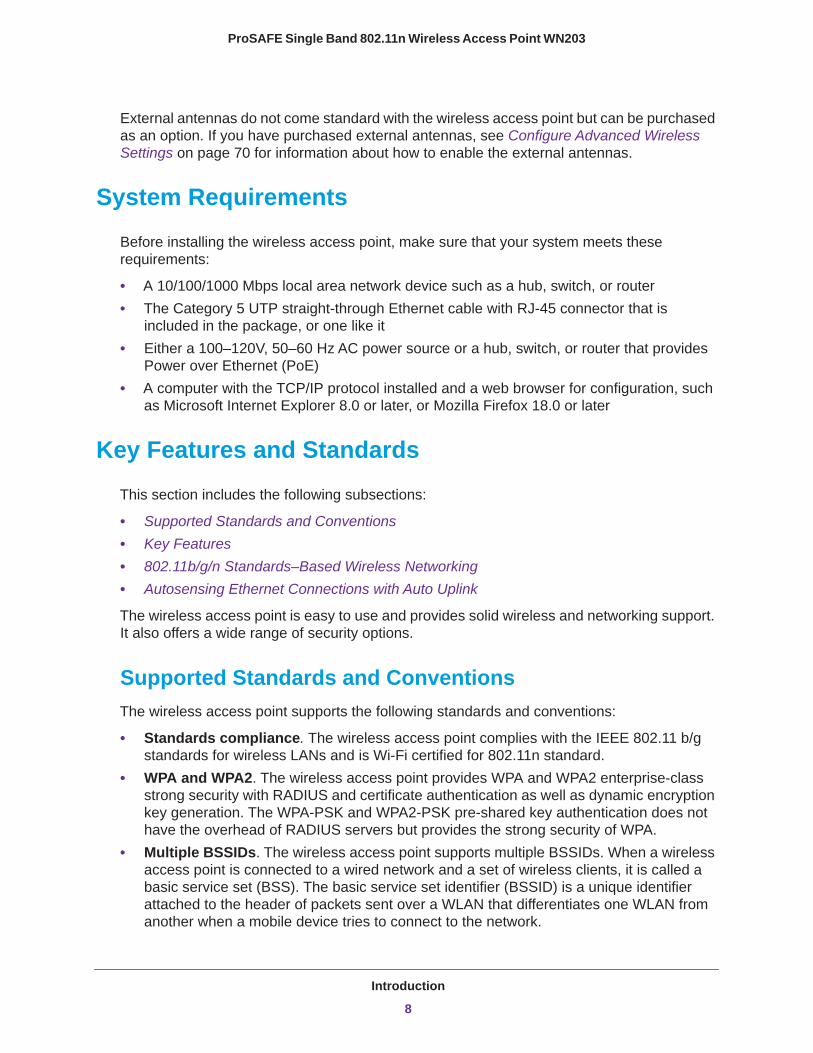
External antennas do not come standard with the wireless access point but can be purchased as an option. If you have purchased external antennas, see Configure Advanced Wireless Settings on page 70 for information about how to enable the external antennas.
System Requirements
Before installing the wireless access point, make sure that your system meets these requirements:
• A 10/100/1000 Mbps local area network device such as a hub, switch, or router• The Category 5 UTP straight-through Ethernet cable with RJ-45 connector that is
included in the package, or one like it• Either a 100–120V, 50–60 Hz AC power source or a hub, switch, or router that provides
Power over Ethernet (PoE)• A computer with the TCP/IP protocol installed and a web browser for configuration, such
as Microsoft Internet Explorer 8.0 or later, or Mozilla Firefox 18.0 or later
Key Features and Standards
This section includes the following subsections:
• Supported Standards and Conventions• Key Features• 802.11b/g/n Standards–Based Wireless Networking• Autosensing Ethernet Connections with Auto Uplink
The wireless access point is easy to use and provides solid wireless and networking support. It also offers a wide range of security options.
Supported Standards and ConventionsThe wireless access point supports the following standards and conventions:
• Standards compliance. The wireless access point complies with the IEEE 802.11 b/g standards for wireless LANs and is Wi-Fi certified for 802.11n standard.
• WPA and WPA2. The wireless access point provides WPA and WPA2 enterprise-class strong security with RADIUS and certificate authentication as well as dynamic encryption key generation. The WPA-PSK and WPA2-PSK pre-shared key authentication does not have the overhead of RADIUS servers but provides the strong security of WPA.
• Multiple BSSIDs. The wireless access point supports multiple BSSIDs. When a wireless access point is connected to a wired network and a set of wireless clients, it is called a basic service set (BSS). The basic service set identifier (BSSID) is a unique identifier attached to the header of packets sent over a WLAN that differentiates one WLAN from another when a mobile device tries to connect to the network.
Introduction
8
ProSAFE Single Band 802.11n Wireless Access Point WN203
The multiple BSSID feature allows you to configure up to eight SSIDs on your wireless access point and assign different configuration settings to each SSID. All the configured SSIDs are active, and the network devices can connect to the wireless access point by using any of these SSIDs.
• DHCP server and client. The DHCP server of the wireless access point can provide a dynamic IP address to wireless clients. The wireless access point can also act as a client and obtain an IP address from a DHCP server on the LAN.
• SNMP. The wireless access point supports Simple Network Management Protocol (SNMP) for Management Information Base (MIB) management.
• STP. The wireless access point supports Spanning Tree Protocol (STP).• 802.1Q VLAN. A network of computers can behave as if they are connected to the same
network even though they might actually be physically on different segments of a LAN. Virtual LANs (VLANs) are configured through software rather than hardware, which makes them very flexible. VLANs are very useful for user and host management, bandwidth allocation, and resource optimization.
Key FeaturesThe wireless access point provides solid functionality, including the following features:
• Multiple operating modes:- Wireless access point. The wireless access point operates as a standard
802.11b/g/n access point for clients.- Point-to-point bridge. The wireless access point communicates with another access
point that functions in bridge mode. You can use this mode with or without client association.
- Point-to-multipoint bridge. The wireless access point is the master for a group of access points that function in bridge mode, that send all traffic to the master, and that do not communicate directly with each other. You can use this mode with or without client association.
- Repeating the wireless signal. The wireless access point does not function as an access point for clients but functions only in point-to-multipoint bridge mode to repeat the wireless signal and send all traffic to a remote access point.
• WMM. Wi-Fi Multimedia (WMM) is a subset of the 802.11e standard. WMM allows wireless traffic to have a range of priorities, depending on the kind of data. Time-dependent information, like video or audio, has a higher priority than normal traffic. For WMM to function correctly, wireless clients also need to support WMM.
• QoS. Quality of Service (QoS) support lets you configure parameters that affect traffic flowing from the wireless access point to the client station and traffic flowing from the client station to the wireless access point.
• Hotspot support. You can allow all HTTP (TCP, port 80) requests to be captured and redirected to the URL you specify.
• Rogue AP detection. Rogue AP filtering ensures that unknown APs are not given access to any part of the secured wireless and wired LAN.
Introduction
9
ProSAFE Single Band 802.11n Wireless Access Point WN203
• Access control. MAC address filtering can ensure that only trusted wireless clients can use the wireless access point to gain access to the wireless and wired LAN.
• Security profiles. When using multiple BSSIDs, you can configure unique security settings (encryption, SSID, and so on) for each BSSID.
• Hidden mode. The SSID is not broadcast, assuring that only clients configured with the correct SSID can connect.
• Telnet and SSH command-line interface. Using an application such as PuTTY, you can access the wireless access point over a Telnet or Secure Shell (SSH) connection and use the command-line interface (CLI) to configure the wireless access point.
• Upgradeable firmware. Firmware is stored in flash memory. You can upgrade it easily, using only your web browser, and you can upgrade it remotely. You can also use the command-line interface.
• Configuration backup. Configuration settings can be backed up to a file and restored.• Secure and economical operation. Adjustable power output allows more secure or
economical operation.• PoE support. Using Power over Ethernet (PoE), any 802.3af-compliant midspan or
end-span sources can supply power to the wireless access point over the Ethernet port. The wireless access point can receive all required power on one Ethernet port from a single PoE source.
• Autosensing Ethernet connection with Auto Uplink™ interface. Connects to 10/100/1000 Mbps IEEE 802.3 Ethernet networks.
• LED indicators. Power, Test, LAN, and WLAN LEDs are easily identified.• VLAN security profiles. Each security profile is automatically allocated a VLAN ID when
the security profile is modified.
802.11b/g/n Standards–Based Wireless NetworkingThe wireless access point provides a bridge between wired Ethernet LANs and 802.11b/g/n-compatible wireless LAN networks. It provides connectivity between wired Ethernet networks and radio-equipped wireless notebook systems, desktop systems, print servers, RFID tags, and other devices.
In addition, the wireless access point supports the following wireless features:
• Aggregation support• Reduced InterFrame spacing support• 2x2 multiple input, multiple output (MIMO) support• Distributed coordinated function (CSMA/CA, back-off procedure, ACK procedure,
retransmission of unacknowledged frames)• RTS/CTS handshake• Beacon generation• Packet fragmentation and reassembly• Auto or long preamble
Introduction
10

ProSAFE Single Band 802.11n Wireless Access Point WN203
• Roaming among wireless access points on the same subnet
Autosensing Ethernet Connections with Auto UplinkThe wireless access point can connect to a standard Ethernet network. The LAN interface is autosensing and capable of full-duplex or half-duplex operation.
The wireless access point incorporates Auto Uplink technology. The Ethernet port automatically senses whether the Ethernet cable plugged into the port should have a “normal” connection such as to a computer or an “uplink” connection such as to a switch or hub. That port then configures itself correctly. This feature also eliminates any concerns about crossover cables, because Auto Uplink accommodates either type of cable to make the right connection.
Hardware Description
This section describes the front and back hardware functions of the wireless access point.
• Front Panel• Back Panel• Bottom Panel with Product Label and Reset to Factory Defaults Button
Front PanelThe LEDs of the wireless access point are described in the following figure and table:
1 2 3 4
Figure 1. Front panel with LEDs
Introduction
11

ProSAFE Single Band 802.11n Wireless Access Point WN203
Table 1. Front panel LEDs
Item LED Description
1 Power Off Power is off.
Green Power is on.
2 Test Off The wireless access point functions normally.
Amber The wireless access point is starting. After about one minute, the LED turns off.
Blinking amber New firmware is being loaded.
3 LAN Off No link is detected on the LAN port.
Amber A 100 Mbps or 10 Mbps link is detected on the LAN port.
Green A 1000 Mbps link is detected on the LAN port.
4 WLAN Off The wireless LAN is not ready, or no wireless activity is detected.
Blue The wireless LAN is ready.
Blinking Blue Wireless activity is detected.
Back Panel
1 2 3 4 5Figure 2. Back panel
The back panel components of the wireless access point, from left to right, are described in the following list:
1. Reverse SMA connector for an optional 2.4 GHz antenna.2. Console port for connecting to an optional console terminal. The port has an RJ-45
connector and supports the following settings: 115200 K default baud rate, (8) data bits, no (N) parity bit, and one (1) stop bit.
3. 10/100/1000BASE-T Gigabit Ethernet RJ-45 LAN port with Auto Uplink (Auto MDI-X) and IEEE 802.3af Power over Ethernet (PoE) support for connection to a switch or router.
Introduction
12
ProSAFE Single Band 802.11n Wireless Access Point WN203
4. Power socket for a 12 VDC, 1A power adapter.5. Reverse SMA connector for an optional 2.4 GHz antenna.
If you have purchased external antennas, see Configure Advanced Wireless Settings on page 70 for information about how to enable the external antennas.
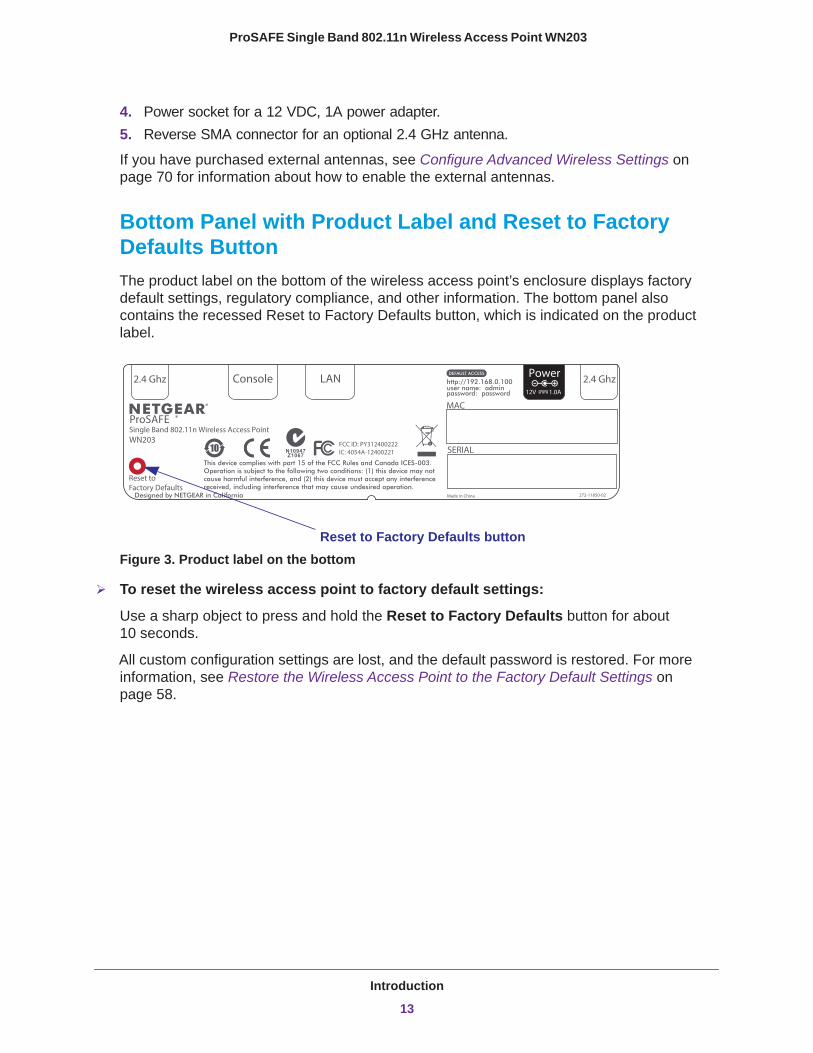
Bottom Panel with Product Label and Reset to Factory Defaults ButtonThe product label on the bottom of the wireless access point’s enclosure displays factory default settings, regulatory compliance, and other information. The bottom panel also contains the recessed Reset to Factory Defaults button, which is indicated on the product label.
user name: admin password: password
http://192.168.0.100
272-11850-02Made in ChinaDesigned by NETGEAR in California
Single Band 802.11n Wireless Access PointWN203
Reset to Factory Defaults
12V 1.0A
Power 2.4 Ghz2.4 Ghz Console LAN
MAC
SERIALThis device complies with part 15 of the FCC Rules and Canada ICES-003. Operation is subject to the following two conditions: (1) this device may not cause harmful interference, and (2) this device must accept any interference received, including interference that may cause undesired operation.
FCC ID: PY312400222IC: 4054A-12400221
ProSAFE
Reset to Factory Defaults buttonFigure 3. Product label on the bottom
To reset the wireless access point to factory default settings:
Use a sharp object to press and hold the Reset to Factory Defaults button for about 10 seconds.
All custom configuration settings are lost, and the default password is restored. For more information, see Restore the Wireless Access Point to the Factory Default Settings on page 58.
Introduction
13

2
2. Installation and Basic ConfigurationThis chapter describes how to install and configure the wireless access point for wireless connectivity to your LAN. This basic configuration enables computers with 2.4 GHz 802.11b/g/n wireless adapters to connect to the Internet or access printers and files on your LAN. In planning your wireless network, consider the level of security required. Chapter 3, Wireless Configuration and Security, describes how to set up wireless security for your network. This chapter includes the following sections:
• What You Need Before You Begin• Install and Configure the Wireless Access Point• Test Basic Wireless Connectivity
14
ProSAFE Single Band 802.11n Wireless Access Point WN203
What You Need Before You Begin
You need to consider the guidelines and requirements in the following sections before you can set up your wireless access point.
See also System Requirements on page 8.
• Wireless Equipment Placement and Range Guidelines• Ethernet Cabling Requirements• LAN Configuration Requirements• Hardware Requirements for Computers on Your LAN• Requirements for Entering IP Addresses
Wireless Equipment Placement and Range GuidelinesThe range of your wireless connection can vary significantly based on the location of the wireless access point. The latency, data throughput performance, and power consumption of wireless adapters also vary depending on your configuration choices.
Note: Failure to follow these guidelines can result in significant performance degradation or inability to connect wirelessly to the wireless access point. For complete performance specifications, see Appendix A, Supplemental Information.
For best results, place your wireless access point according to the following general guidelines:
• Near the center of the area in which the wireless devices will operate.• In an elevated location such as a high shelf where the wirelessly connected devices have
line-of-sight access (even if through walls).• Away from sources of interference, such as computers, microwaves ovens, and 2.4 GHz
cordless phones.• Away from large metal surfaces or water.
The time it takes to establish a wireless connection can vary depending on both your security settings and placement. WEP connections can take slightly longer to establish. Also, WEP encryption can consume more battery power on a notebook computer.
Installation and Basic Configuration
15
ProSAFE Single Band 802.11n Wireless Access Point WN203
Ethernet Cabling RequirementsThe wireless access point connects to your LAN using twisted-pair Category 5 Ethernet cable with RJ-45 connectors.
LAN Configuration RequirementsFor the initial configuration of your wireless access point, you need to connect a computer to the wireless access point.
Hardware Requirements for Computers on Your LANTo connect to the wireless access point on your network, each computer needs to have an 802.11b/g/n wireless adapter installed.
Requirements for Entering IP AddressesThe fourth octet of an IP address needs to be between 0 and 255 (both inclusive). This requirement applies to any IP address that you enter on a screen of the web management interface.
Install and Configure the Wireless Access Point
Install and configure your wireless access point in the order of the following sections:
1. Connect the Wireless Access Point to a Computer2. Log In to the Wireless Access Point3. Configure Basic General System Settings and Time Settings4. Configure the IP Settings5. Configure the Optional DHCP Server6. Configure the Basic Wireless Settings
Before installing the wireless access point, make sure that your Ethernet network functions. After you have connected the wireless access point to the Ethernet network, computers with 802.11b/g/n wireless adapters are able to communicate with the Ethernet network.
Before you start the installation and configuration process, verify that you have met all the system requirements. See System Requirements on page 8.
Installation and Basic Configuration
16
ProSAFE Single Band 802.11n Wireless Access Point WN203
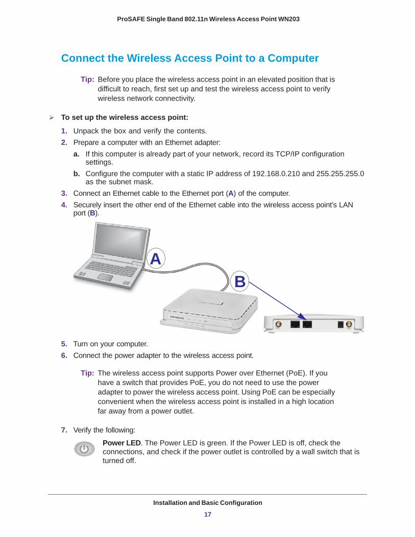
Connect the Wireless Access Point to a Computer
Tip: Before you place the wireless access point in an elevated position that is difficult to reach, first set up and test the wireless access point to verify wireless network connectivity.
To set up the wireless access point:
1. Unpack the box and verify the contents.2. Prepare a computer with an Ethernet adapter:
a. If this computer is already part of your network, record its TCP/IP configuration settings.
b. Configure the computer with a static IP address of 192.168.0.210 and 255.255.255.0 as the subnet mask.
3. Connect an Ethernet cable to the Ethernet port (A) of the computer.4. Securely insert the other end of the Ethernet cable into the wireless access point’s LAN
port (B).
AB
5. Turn on your computer.6. Connect the power adapter to the wireless access point.
Tip: The wireless access point supports Power over Ethernet (PoE). If you have a switch that provides PoE, you do not need to use the power adapter to power the wireless access point. Using PoE can be especially convenient when the wireless access point is installed in a high location far away from a power outlet.
7. Verify the following:
Power LED. The Power LED is green. If the Power LED is off, check the connections, and check if the power outlet is controlled by a wall switch that is turned off.
Installation and Basic Configuration
17
ProSAFE Single Band 802.11n Wireless Access Point WN203
Test LED. The Test LED is amber. After about one minute, the Test LED turns off.
LAN LED. The LAN LED indicates the LAN speed for the LAN port: green for 1000 Mbps or amber for 100 Mbps or 10 Mbps.
WLAN LED. The WLAN LED is blue when the wireless LAN (WLAN) is ready.
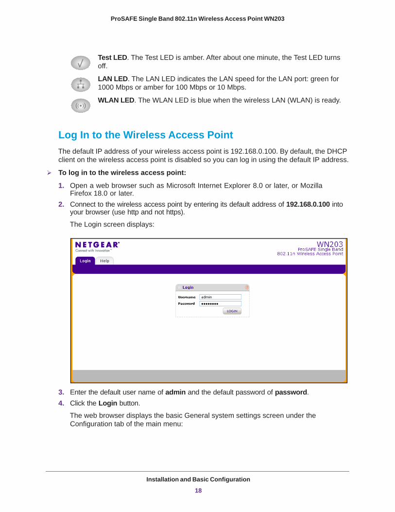
Log In to the Wireless Access PointThe default IP address of your wireless access point is 192.168.0.100. By default, the DHCP client on the wireless access point is disabled so you can log in using the default IP address.
To log in to the wireless access point:
1. Open a web browser such as Microsoft Internet Explorer 8.0 or later, or Mozilla Firefox 18.0 or later.
2. Connect to the wireless access point by entering its default address of 192.168.0.100 into your browser (use http and not https).
The Login screen displays:
3. Enter the default user name of admin and the default password of password.4. Click the Login button.
The web browser displays the basic General system settings screen under the Configuration tab of the main menu:
Installation and Basic Configuration
18
ProSAFE Single Band 802.11n Wireless Access Point WN203
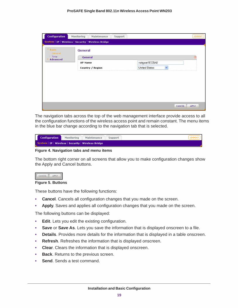
The navigation tabs across the top of the web management interface provide access to all the configuration functions of the wireless access point and remain constant. The menu items in the blue bar change according to the navigation tab that is selected.
Figure 4. Navigation tabs and menu items
The bottom right corner on all screens that allow you to make configuration changes show the Apply and Cancel buttons.
Figure 5. Buttons
These buttons have the following functions:
• Cancel. Cancels all configuration changes that you made on the screen.• Apply. Saves and applies all configuration changes that you made on the screen.
The following buttons can be displayed:
• Edit. Lets you edit the existing configuration.• Save or Save As. Lets you save the information that is displayed onscreen to a file.• Details. Provides more details for the information that is displayed in a table onscreen.• Refresh. Refreshes the information that is displayed onscreen.• Clear. Clears the information that is displayed onscreen.• Back. Returns to the previous screen.• Send. Sends a test command.
Installation and Basic Configuration
19

ProSAFE Single Band 802.11n Wireless Access Point WN203
Configure Basic General System Settings and Time SettingsAfter you have successfully logged in to the wireless access point, the basic General system settings screen displays.
To configure basic system settings:
1. Select Configuration > System > Basic > General. The basic General system settings screen displays:
2. Configure the settings as described in the following table:
Setting Description
AP Name This unique name is the wireless access point NetBIOS name. The name is printed on the label of the wireless access point. The default is netgearxxxxxx, in which xxxxxx represents the last six digits of the wireless access point MAC address. You can replace the default name with a unique name up to 15 characters long. The access point name can be retrieved through SNMP.
Country / Region From the Country / Region drop-down menu, select the country where the wireless access point is installed.
3. Click the Apply button.
Note: It might not be legal to operate this wireless access point in a region other than one of the regions that you can select from the drop-down menu.
Installation and Basic Configuration
20
ProSAFE Single Band 802.11n Wireless Access Point WN203
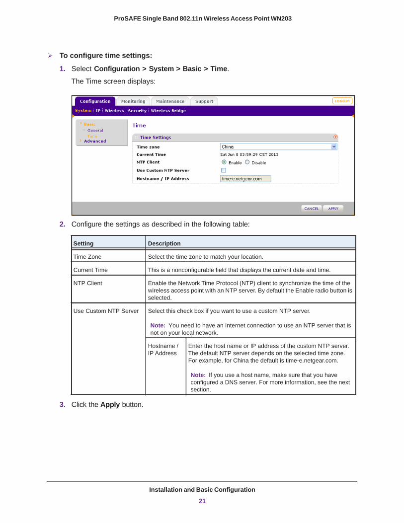
To configure time settings:
1. Select Configuration > System > Basic > Time.
The Time screen displays:
2. Configure the settings as described in the following table:
Setting Description
Time Zone Select the time zone to match your location.
Current Time This is a nonconfigurable field that displays the current date and time.
NTP Client Enable the Network Time Protocol (NTP) client to synchronize the time of the wireless access point with an NTP server. By default the Enable radio button is selected.
Use Custom NTP Server Select this check box if you want to use a custom NTP server.
Hostname / IP Address
Enter the host name or IP address of the custom NTP server. The default NTP server depends on the selected time zone. For example, for China the default is time-e.netgear.com.
3. Click the Apply button.
Note: You need to have an Internet connection to use an NTP server that is not on your local network.
Note: If you use a host name, make sure that you have configured a DNS server. For more information, see the next section.
Installation and Basic Configuration
21

ProSAFE Single Band 802.11n Wireless Access Point WN203
Configure the IP Settings
WARNING:
If you enable the DHCP client, the IP address of the wireless access point changes when you click the Apply button, causing you to lose your connection to the wireless access point. You then need to use the new IP address to reconnect to the wireless access point.
Tip: If you enable the DHCP client on the wireless access point, you can discover the new IP address of the wireless access point by accessing the DHCP server on your LAN, or by using a network IP address scanner application.
To configure the IP settings:
1. Select Configuration > IP > IP Settings.
The IP Settings screen displays:
Installation and Basic Configuration
22
ProSAFE Single Band 802.11n Wireless Access Point WN203
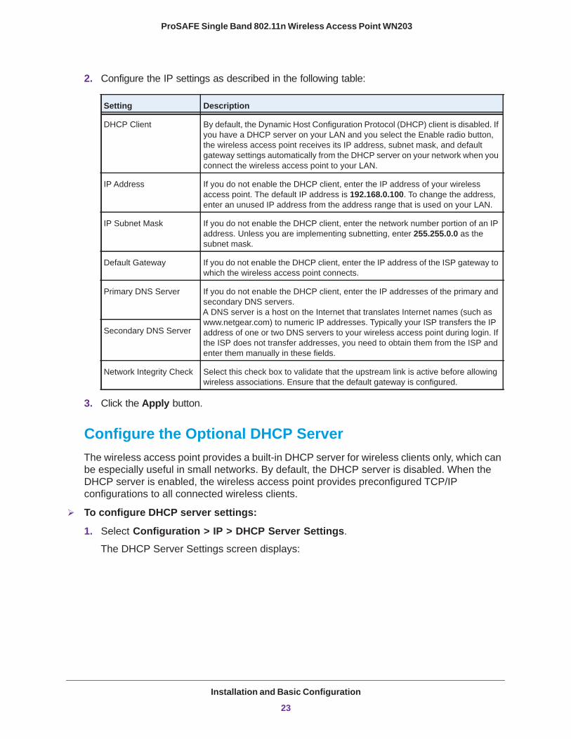
2. Configure the IP settings as described in the following table:
Setting Description
DHCP Client By default, the Dynamic Host Configuration Protocol (DHCP) client is disabled. If you have a DHCP server on your LAN and you select the Enable radio button, the wireless access point receives its IP address, subnet mask, and default gateway settings automatically from the DHCP server on your network when you connect the wireless access point to your LAN.
IP Address If you do not enable the DHCP client, enter the IP address of your wireless access point. The default IP address is 192.168.0.100. To change the address, enter an unused IP address from the address range that is used on your LAN.
IP Subnet Mask If you do not enable the DHCP client, enter the network number portion of an IP address. Unless you are implementing subnetting, enter 255.255.0.0 as the subnet mask.
Default Gateway If you do not enable the DHCP client, enter the IP address of the ISP gateway to which the wireless access point connects.
Primary DNS Server
If you do not enable the DHCP client, enter the IP addresses of the primary and secondary DNS servers. A DNS server is a host on the Internet that translates Internet names (such as www.netgear.com) to numeric IP addresses. Typically your ISP transfers the IP address of one or two DNS servers to your wireless access point during login. If the ISP does not transfer addresses, you need to obtain them from the ISP and enter them manually in these fields.
Secondary DNS Server
Network Integrity Check Select this check box to validate that the upstream link is active before allowing wireless associations. Ensure that the default gateway is configured.
3. Click the Apply button.
Configure the Optional DHCP ServerThe wireless access point provides a built-in DHCP server for wireless clients only, which can be especially useful in small networks. By default, the DHCP server is disabled. When the DHCP server is enabled, the wireless access point provides preconfigured TCP/IP configurations to all connected wireless clients.
To configure DHCP server settings:
1. Select Configuration > IP > DHCP Server Settings.
The DHCP Server Settings screen displays:
Installation and Basic Configuration
23
ProSAFE Single Band 802.11n Wireless Access Point WN203
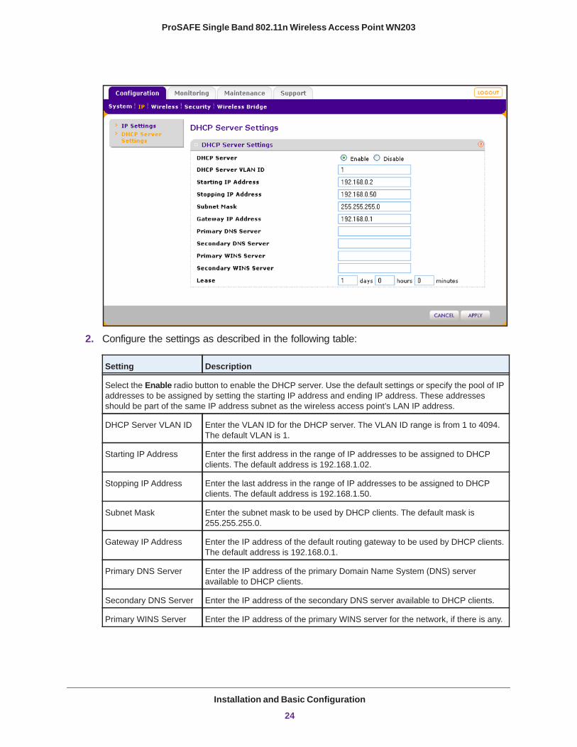
2. Configure the settings as described in the following table:
Setting Description
Select the Enable radio button to enable the DHCP server. Use the default settings or specify the pool of IP addresses to be assigned by setting the starting IP address and ending IP address. These addresses should be part of the same IP address subnet as the wireless access point’s LAN IP address.
DHCP Server VLAN ID Enter the VLAN ID for the DHCP server. The VLAN ID range is from 1 to 4094. The default VLAN is 1.
Starting IP Address Enter the first address in the range of IP addresses to be assigned to DHCP clients. The default address is 192.168.1.02.
Stopping IP Address Enter the last address in the range of IP addresses to be assigned to DHCP clients. The default address is 192.168.1.50.
Subnet Mask Enter the subnet mask to be used by DHCP clients. The default mask is 255.255.255.0.
Gateway IP Address Enter the IP address of the default routing gateway to be used by DHCP clients. The default address is 192.168.0.1.
Primary DNS Server Enter the IP address of the primary Domain Name System (DNS) server available to DHCP clients.
Secondary DNS Server Enter the IP address of the secondary DNS server available to DHCP clients.
Primary WINS Server Enter the IP address of the primary WINS server for the network, if there is any.
Installation and Basic Configuration
24
ProSAFE Single Band 802.11n Wireless Access Point WN203
3. Click the Apply button.
Configure the Basic Wireless SettingsFor proper compliance and compatibility between similar products in your coverage area, you need to configure the 802.11b/g/n wireless adapter settings correctly, including the operating channel and country. You also need to configure the basic wireless network settings for wireless devices to connect to your network. For other wireless features, including wireless security, see Chapter 3, Wireless Configuration and Security.
Operating Frequency (Channel) GuidelinesYou do not need to change the operating frequency (channel) unless you notice interference problems or you place the wireless access point near another wireless access point. If you do change the operating frequency, observe the following guidelines:
• Wireless access points use a fixed channel. You can select a channel that provides the least interference and best performance. In the United States and Canada, 11 channels are available.
• If you are using multiple wireless access points, it is better if adjacent wireless access points use different radio frequency channels to reduce interference. The recommended channel spacing between adjacent wireless access points is five channels (for example, use Channels 1 and 6, or 6 and 11, or 1 and 11).
• In infrastructure mode (which is the default mode for the wireless access point), wireless clients normally scan all channels, looking for a wireless access point. If more than one wireless access point is available, and the wireless access points use the same SSID, a wireless client uses the wireless access point with the strongest signal.
Configure 802.11b/bg/ng Wireless SettingsThe basic Wireless Settings screen lets you configure the wireless mode, SSID, and other wireless settings.
WARNING:
If you configure the wireless access point from a wireless computer and you change the wireless access point’s SSID, channel, or wireless security settings, you lose your wireless connection when you click the Apply button. You then need to change the wireless settings of your computer to match the wireless access point’s new settings.
Secondary WINS Server Enter the IP address of the secondary WINS server for the network, if there is any.
Lease Enter the period that the DHCP server grants to DHCP clients to use the assigned IP addresses. The default time is 1 (one day).
Setting Description
Installation and Basic Configuration
25
ProSAFE Single Band 802.11n Wireless Access Point WN203
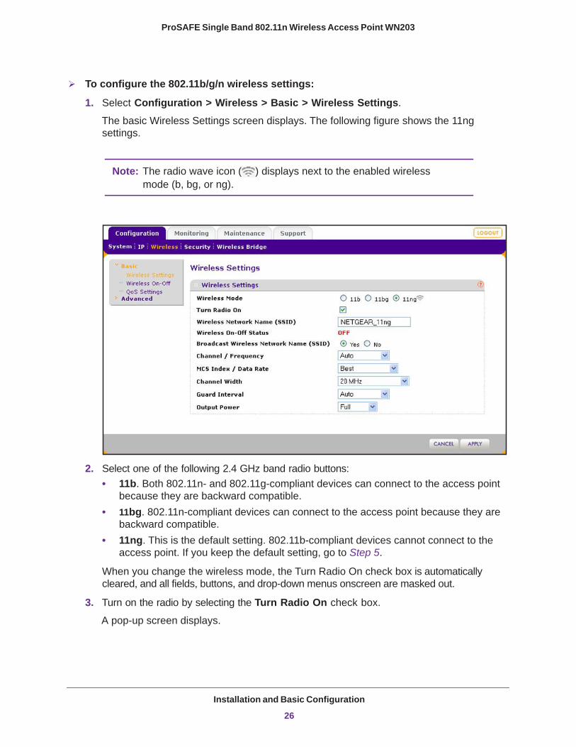
To configure the 802.11b/g/n wireless settings:
1. Select Configuration > Wireless > Basic > Wireless Settings.
The basic Wireless Settings screen displays. The following figure shows the 11ng settings.
Note: The radio wave icon ( ) displays next to the enabled wireless mode (b, bg, or ng).
2. Select one of the following 2.4 GHz band radio buttons:• 11b. Both 802.11n- and 802.11g-compliant devices can connect to the access point
because they are backward compatible.• 11bg. 802.11n-compliant devices can connect to the access point because they are
backward compatible.• 11ng. This is the default setting. 802.11b-compliant devices cannot connect to the
access point. If you keep the default setting, go to Step 5.
When you change the wireless mode, the Turn Radio On check box is automatically cleared, and all fields, buttons, and drop-down menus onscreen are masked out.
3. Turn on the radio by selecting the Turn Radio On check box.
A pop-up screen displays.
Installation and Basic Configuration
26

ProSAFE Single Band 802.11n Wireless Access Point WN203
Note: Under normal conditions, you want the radio to be turned on. Turning off the radio disables access through the wireless access point, which can be helpful for configuration, network tuning, or troubleshooting activities.
4. Click the OK button to confirm the change of wireless mode.
The change does not take effect until after you have completed the wireless configuration and have clicked the Apply button.
5. Specify the remaining wireless settings as described the following table:
Setting Descriptions
Wireless Network Name (SSID)
Enter a 32-character (maximum) service set identifier (SSID); the characters are case-sensitive. The default is NETGEAR_11ng. The SSID assigned to a wireless device needs to match the wireless access point’s SSID for the wireless device to communicate with the wireless access point. If the SSIDs do not match, you do not get a wireless connection to the wireless access point.
Wireless On-Off Status This field is not configurable. It shows the status of the wireless scheduler. For more information, see Schedule the Wireless Radios to Be Turned Off on page 49.
Broadcast Wireless Network Name (SSID)
Select the Yes radio button to enable the wireless access point to broadcast its SSID, allowing wireless clients that have a null (blank) SSID to adopt the wireless access point’s SSID. Yes is the default setting. To prevent the SSID from being broadcast, select the No radio button.
Channel / Frequency From the drop-down menu, select the channel you wish to use for your wireless LAN. The wireless channels and frequencies depend on the country and wireless mode. The default setting is Auto.
Note: You should not have to change the wireless channel unless you experience interference (indicated by lost connections or slow data transfers). If this situation occurs, you might want to experiment with different channels to see which is the best. For more information, see Operating Frequency (Channel) Guidelines on page 25.
Note: For more information about available channels and frequencies, see Technical Specifications on page 107.
Installation and Basic Configuration
27
ProSAFE Single Band 802.11n Wireless Access Point WN203
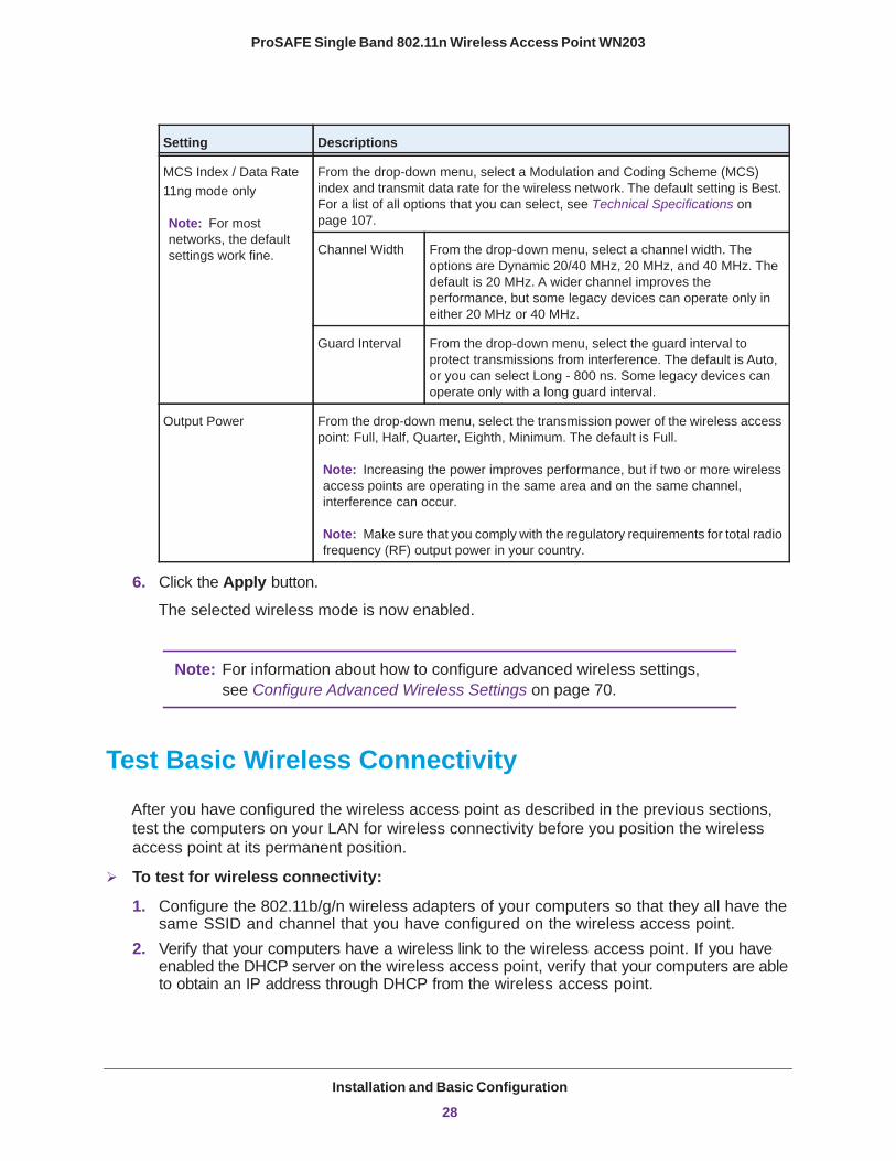
6. Click the Apply button.
The selected wireless mode is now enabled.
Note: For information about how to configure advanced wireless settings, see Configure Advanced Wireless Settings on page 70.
Test Basic Wireless Connectivity
After you have configured the wireless access point as described in the previous sections, test the computers on your LAN for wireless connectivity before you position the wireless access point at its permanent position.
To test for wireless connectivity:
1. Configure the 802.11b/g/n wireless adapters of your computers so that they all have the same SSID and channel that you have configured on the wireless access point.
2. Verify that your computers have a wireless link to the wireless access point. If you have enabled the DHCP server on the wireless access point, verify that your computers are able to obtain an IP address through DHCP from the wireless access point.
MCS Index / Data Rate11ng mode only
Note: For most networks, the default settings work fine.
From the drop-down menu, select a Modulation and Coding Scheme (MCS) index and transmit data rate for the wireless network. The default setting is Best. For a list of all options that you can select, see Technical Specifications on page 107.
Channel Width From the drop-down menu, select a channel width. The options are Dynamic 20/40 MHz, 20 MHz, and 40 MHz. The default is 20 MHz. A wider channel improves the performance, but some legacy devices can operate only in either 20 MHz or 40 MHz.
Guard Interval From the drop-down menu, select the guard interval to protect transmissions from interference. The default is Auto, or you can select Long - 800 ns. Some legacy devices can operate only with a long guard interval.
Output Power From the drop-down menu, select the transmission power of the wireless access point: Full, Half, Quarter, Eighth, Minimum. The default is Full.
Note: Increasing the power improves performance, but if two or more wireless access points are operating in the same area and on the same channel, interference can occur.
Note: Make sure that you comply with the regulatory requirements for total radio frequency (RF) output power in your country.
Setting Descriptions
Installation and Basic Configuration
28
ProSAFE Single Band 802.11n Wireless Access Point WN203
3. Verify network connectivity by using a browser such as Microsoft Internet Explorer 8.0 or later, or Mozilla Firefox 18.0 or later to browse the Internet, or check for file and printer access on your network.
Note: If you have trouble connecting to the wireless access point, see Chapter 7, Troubleshooting.
NETGEAR recommends that you complete the following tasks before you deploy the wireless access point in your network:
• Configure wireless security and other wireless features. See Chapter 3, Wireless Configuration and Security.
• Configure any additional features that you might need. See Chapter 4, Management, and Chapter 5, Advanced Configuration.
After you have completed the configuration of the wireless access point, you can reconfigure the computer that you used for this process back to its original TCP/IP settings.
Installation and Basic Configuration
29
3
3. Wireless Configuration and SecurityThis chapter describes how to configure the wireless features of the wireless access point. The chapter includes the following sections:
• Before You Configure Wireless Security• Wireless Data Security Options• Security Profiles• Configure RADIUS Server Settings• Restrict Wireless Access by MAC Address• Schedule the Wireless Radios to Be Turned Off• Configure Basic Wireless Quality of Service
30
ProSAFE Single Band 802.11n Wireless Access Point WN203
Before You Configure Wireless Security
Before you set up wireless security and additional wireless features that are described in this chapter, connect the wireless access point, get the Internet connection working, set the country or region correctly, and configure the 802.11b, 11bg, or 11ng wireless settings. See Chapter 2, Installation and Basic Configuration.
The wireless access point functions with an Ethernet LAN connection. Make sure that you have verified wireless connectivity before you set up wireless security and additional wireless features.
WARNING:
If you are configuring the wireless access point from a wireless computer and you change the wireless access point’s SSID, channel, or wireless security settings, you lose your wireless connection when you click the Apply button. You then need to change the wireless settings of your computer to match the wireless access point’s new settings.
Wireless Data Security Options
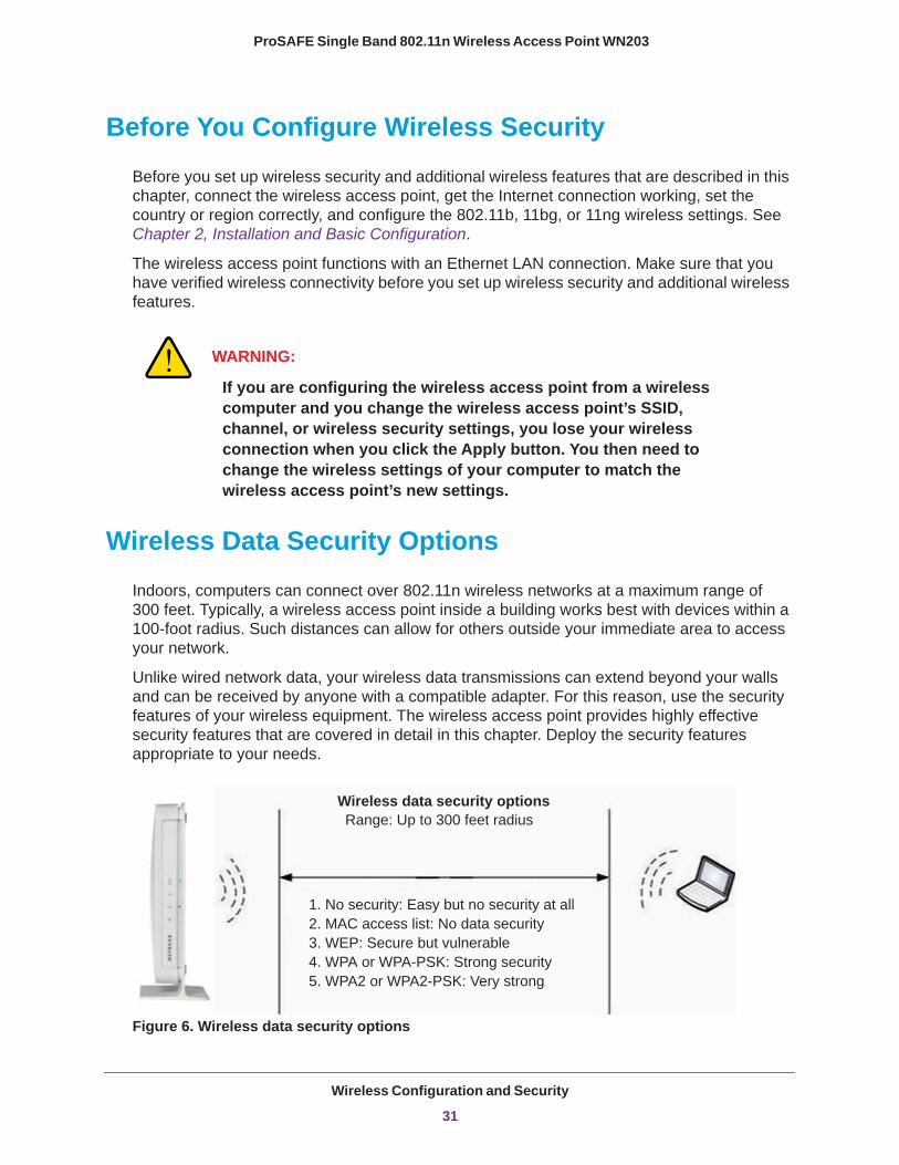
Indoors, computers can connect over 802.11n wireless networks at a maximum range of 300 feet. Typically, a wireless access point inside a building works best with devices within a 100-foot radius. Such distances can allow for others outside your immediate area to access your network.
Unlike wired network data, your wireless data transmissions can extend beyond your walls and can be received by anyone with a compatible adapter. For this reason, use the security features of your wireless equipment. The wireless access point provides highly effective security features that are covered in detail in this chapter. Deploy the security features appropriate to your needs.
Wireless data security optionsRange: Up to 300 feet radius
1. No security: Easy but no security at all 2. MAC access list: No data security 3. WEP: Secure but vulnerable 4. WPA or WPA-PSK: Strong security 5. WPA2 or WPA2-PSK: Very strong
Figure 6. Wireless data security options
Wireless Configuration and Security
31
ProSAFE Single Band 802.11n Wireless Access Point WN203
There are many ways in which you can enhance the security of your wireless network:
• Use multiple BSSIDs combined with VLANs. You can configure combinations of VLANS and BSSIDs (security profiles) with stronger or less restrictive access security according to your requirements. For example, visitors could be given wireless Internet access but be excluded from any access to your internal network.
For information about how to configure BSSIDs, see Configure and Enable Security Profiles on page 36.
• Restrict access based by MAC address. You can allow only trusted devices to connect so that unknown devices cannot wirelessly connect to the wireless access point. Restricting access by MAC address adds an obstacle against unwanted access to your network, but the data broadcast over the wireless link is fully exposed.
For information about how to restrict access by MAC address, see Restrict Wireless Access by MAC Address on page 46.
• Turn off the broadcast of the wireless network name (SSID). If you disable broadcast of the SSID, only devices that have the correct SSID can connect. This nullifies the wireless network discovery feature of some products, such as Windows XP, but the data is still exposed.
For information about how to turn off broadcast of the SSID, see Configure and Enable Security Profiles on page 36.
• WEP. Wired Equivalent Privacy (WEP) data encryption provides data security. WEP shared key authentication and WEP data encryption block all but the most determined eavesdropper. This data encryption mode has been superseded by WPA-PSK and WPA2-PSK.
For information about how to configure WEP, see the following sections:
- Configure and Enable Security Profiles on page 36- Configure an Open System with WEP or Shared Key with WEP on page 40
• Legacy 802.1X. Legacy 802.1X uses RADIUS-based 802.1x authentication but no data encryption.
For information about how to configure Legacy 802.1X, see the following sections:- Configure and Enable Security Profiles on page 36- Configure Legacy 802.1X on page 42
• WPA and WPA-PSK (TKIP). Wi-Fi Protected Access (WPA) data encryption provides strong data security with Temporal Key Integrity Protocol (TKIP) encryption. The very strong authentication along with dynamic per-frame rekeying of WPA makes it virtually impossible to compromise.
WPA uses RADIUS-based 802.1x authentication; for more information, see the following sections:- Configure and Enable Security Profiles on page 36- Configure WPA with RADIUS, WPA2 with RADIUS, and WPA & WPA2 with RADIUS
on page 42
Wireless Configuration and Security
32
ProSAFE Single Band 802.11n Wireless Access Point WN203
WPA-PSK uses a pre-shared key (PSK) for authentication; for more information, see the following sections:
- Configure and Enable Security Profiles on page 36- Configure WPA-PSK, WPA2-PSK, and WPA-PSK & WPA2-PSK on page 43
• WPA2 and WPA2-PSK (AES). Wi-Fi Protected Access version 2 (WPA2) data encryption provides strong data security with Advanced Encryption Standard (AES) encryption. The very strong authentication along with dynamic per-frame rekeying of WPA2 makes it virtually impossible to compromise.
WPA2 uses RADIUS-based 802.1x authentication; for more information, see the following sections:
- Configure and Enable Security Profiles on page 36- Configure WPA with RADIUS, WPA2 with RADIUS, and WPA & WPA2 with RADIUS
on page 42
WPA2-PSK uses a pre-shared key (PSK) for authentication; for more information, see the following sections:
- Configure and Enable Security Profiles on page 36- Configure WPA-PSK, WPA2-PSK, and WPA-PSK & WPA2-PSK on page 43
• WPA & WPA2 and WPA-PSK & WPA2-PSK mixed modes. These modes support data encryption either with both WPA and WPA2 clients or with both WPA-PSK and WPA2-PSK clients and provide the most reliable security.
WPA & WPA2 uses RADIUS-based 802.1x authentication; for more information, see the following sections:
- Configure and Enable Security Profiles on page 36- Configure WPA with RADIUS, WPA2 with RADIUS, and WPA & WPA2 with RADIUS
on page 42
WPA-PSK & WPA2-PSK uses a pre-shared key (PSK) for authentication; for more information, see the following sections:
- Configure and Enable Security Profiles on page 36- Configure WPA-PSK, WPA2-PSK, and WPA-PSK & WPA2-PSK on page 43
Security Profiles
This section describes the main components of security profiles and explains how to configure and enable security profiles.
• Security Profile Concepts• Write Down Your Wireless Network Settings• Configure and Enable Security Profiles
Wireless Configuration and Security
33
ProSAFE Single Band 802.11n Wireless Access Point WN203
Security profiles let you configure unique security settings for each SSID on each radio of the wireless access point. For each radio, the wireless access point supports up to eight security profiles (BSSIDs) that you can configure on the individual Edit Wireless Network screens that are accessible from the Edit Security Profile screen (see Configure and Enable Security Profiles on page 36).
Security Profile ConceptsSecurity profiles include the following main components:
• Network authentication The wireless access point is set by default as an open system with no authentication. When you configure network authentication, bear in mind that not all wireless adapters support WPA or WPA2. Consult the product documentation for your wireless adapter and WPA or WPA2 client software for instructions about how to configure WPA or WPA2 settings.
For information about the types of network authentication that the wireless access point supports, see Configure and Enable Security Profiles on page 36.
• Data encryption The available data encryption options depend on the network authentication setting that you select (the default is no encryption). The data encryption settings are explained in Configure and Enable Security Profiles on page 36.
• Wireless client security separation If this feature is enabled, the associated wireless clients (using the same SSID) are not able to communicate with each other. This feature is useful for hotspots and other public access situations. By default, wireless client separation is disabled. For more information, see Configure and Enable Security Profiles on page 36.
• VLAN ID If this feature is enabled and if the network devices (hubs and switches) on your LAN support the VLAN (802.1Q) standard, the default VLAN ID for the wireless access point is associated with each profile. The default VLAN ID needs to match the IDs that are used by the other network devices. For more information, see Configure and Enable Security Profiles on page 36.
Some concepts and guidelines regarding the SSID are explained in the following list:
• A basic service set (BSS) consists of a group of wireless clients and a single wireless access point that use the same security profile or service set identifier (BSSID). The actual identifier in the BSSID is the MAC address of the wireless radio. (A wireless radio can have multiple MAC addresses, one for each security profile.)
• An extended service set (ESS) consists of a group of wireless clients and multiple wireless access points that use the same identifier (ESSID).
• Different wireless access points within an ESS can use different channels. To reduce interference, adjacent wireless access points should use different channels.
• Roaming is the ability of wireless clients to connect wirelessly when they physically move from one BSS to another one within the same ESS. The wireless client automatically changes to the wireless access point with the least interference or best performance.
Wireless Configuration and Security
34
ProSAFE Single Band 802.11n Wireless Access Point WN203
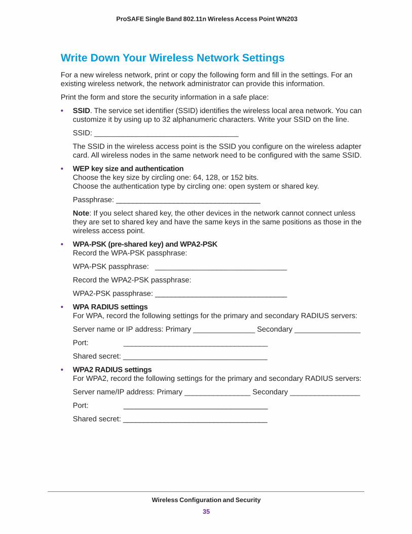
Write Down Your Wireless Network SettingsFor a new wireless network, print or copy the following form and fill in the settings. For an existing wireless network, the network administrator can provide this information.
Print the form and store the security information in a safe place:
• SSID. The service set identifier (SSID) identifies the wireless local area network. You can customize it by using up to 32 alphanumeric characters. Write your SSID on the line.
SSID: ___________________________________
The SSID in the wireless access point is the SSID you configure on the wireless adapter card. All wireless nodes in the same network need to be configured with the same SSID.
• WEP key size and authentication Choose the key size by circling one: 64, 128, or 152 bits. Choose the authentication type by circling one: open system or shared key.
Passphrase: ___________________________________
Note: If you select shared key, the other devices in the network cannot connect unless they are set to shared key and have the same keys in the same positions as those in the wireless access point.
• WPA-PSK (pre-shared key) and WPA2-PSK Record the WPA-PSK passphrase:
WPA-PSK passphrase: ________________________________
Record the WPA2-PSK passphrase:
WPA2-PSK passphrase: ________________________________
• WPA RADIUS settings For WPA, record the following settings for the primary and secondary RADIUS servers:
Server name or IP address: Primary _______________ Secondary ________________
Port: ___________________________________
Shared secret: ___________________________________
• WPA2 RADIUS settings For WPA2, record the following settings for the primary and secondary RADIUS servers:
Server name/IP address: Primary ________________ Secondary _________________
Port: ___________________________________
Shared secret: ___________________________________
Wireless Configuration and Security
35
ProSAFE Single Band 802.11n Wireless Access Point WN203
Configure and Enable Security ProfilesThe wireless access point is set by default as an open system with no authentication. When you configure network authentication, bear in mind the following:
• If you are using access point mode (which is the default mode if you did not enable wireless bridging), all options are available. In other modes such as bridge mode, some options might be unavailable.
• Not all wireless adapters support WPA or WPA2. Consult the product documentation for your wireless adapter and WPA or WPA2 client software for instructions about how to configure WPA or WPA2 settings.
WARNING:
If you use a wireless computer to configure wireless security settings, you are disconnected when you click the Apply button. Reconfigure your wireless computer to match the new settings, or access the wireless access point from a wired computer to make further changes.
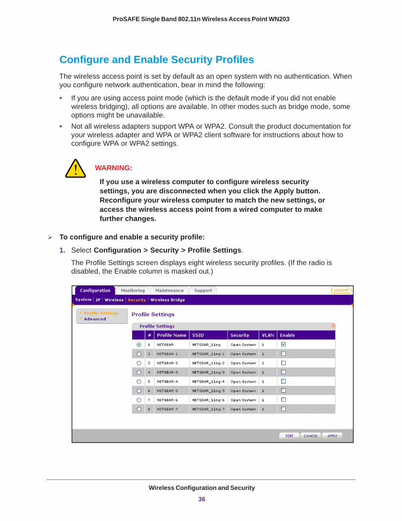
To configure and enable a security profile:
1. Select Configuration > Security > Profile Settings. The Profile Settings screen displays eight wireless security profiles. (If the radio is disabled, the Enable column is masked out.)
Wireless Configuration and Security
36
ProSAFE Single Band 802.11n Wireless Access Point WN203
The following table explains the fields of the Profile Settings screen:
Setting Description
Profile Name The unique name of the wireless security profile that makes it easy to recognize the profile.
SSID The wireless network name (SSID) for the wireless security profile.
Security The configured wireless authentication method for the wireless security profile.
VLAN The default VLAN ID that is associated with the wireless security profile.
Enable The check box that lets you select the wireless security profile so you can enable it by clicking the Apply button.
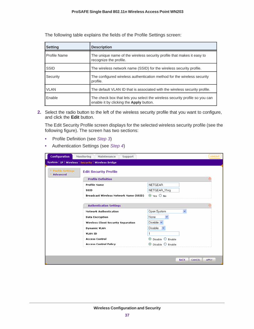
2. Select the radio button to the left of the wireless security profile that you want to configure, and click the Edit button.
The Edit Security Profile screen displays for the selected wireless security profile (see the following figure). The screen has two sections:
• Profile Definition (see Step 3)• Authentication Settings (see Step 4)
Wireless Configuration and Security
37
ProSAFE Single Band 802.11n Wireless Access Point WN203
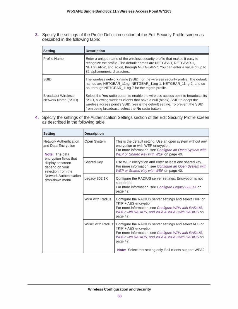
3. Specify the settings of the Profile Definition section of the Edit Security Profile screen as described in the following table:
Setting Description
Profile Name Enter a unique name of the wireless security profile that makes it easy to recognize the profile. The default names are NETGEAR, NETGEAR-1, NETGEAR-2, and so on, through NETGEAR-7. You can enter a value of up to 32 alphanumeric characters.
SSID The wireless network name (SSID) for the wireless security profile. The default names are NETGEAR_11ng, NETGEAR_11ng-1, NETGEAR_11ng-2, and so on, through NETGEAR_11ng-7 for the eighth profile.
Broadcast Wireless Network Name (SSID)
Select the Yes radio button to enable the wireless access point to broadcast its SSID, allowing wireless clients that have a null (blank) SSID to adopt the wireless access point’s SSID. Yes is the default setting. To prevent the SSID from being broadcast, select the No radio button.
4. Specify the settings of the Authentication Settings section of the Edit Security Profile screen as described in the following table.
Setting Description
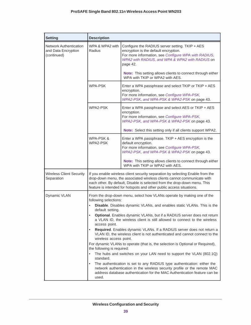
Network Authentication and Data Encryption
Note: The data encryption fields that display onscreen depend on your selection from the Network Authentication drop-down menu.
Open System This is the default setting. Use an open system without any encryption or with WEP encryption. For more information, see Configure an Open System with WEP or Shared Key with WEP on page 40.
Shared Key Use WEP encryption and enter at least one shared key. For more information, see Configure an Open System with WEP or Shared Key with WEP on page 40.
Legacy 802.1X Configure the RADIUS server settings. Encryption is not supported. For more information, see Configure Legacy 802.1X on page 42.
WPA with Radius Configure the RADIUS server settings and select TKIP or TKIP + AES encryption. For more information, see Configure WPA with RADIUS, WPA2 with RADIUS, and WPA & WPA2 with RADIUS on page 42.
WPA2 with Radius Configure the RADIUS server settings and select AES or TKIP + AES encryption. For more information, see Configure WPA with RADIUS, WPA2 with RADIUS, and WPA & WPA2 with RADIUS on page 42.
Note: Select this setting only if all clients support WPA2.
Wireless Configuration and Security
38
ProSAFE Single Band 802.11n Wireless Access Point WN203
Network Authentication and Data Encryption (continued)
WPA & WPA2 with Radius
Configure the RADIUS server setting. TKIP + AES encryption is the default encryption. For more information, see Configure WPA with RADIUS, WPA2 with RADIUS, and WPA & WPA2 with RADIUS on page 42.
Note: This setting allows clients to connect through either WPA with TKIP or WPA2 with AES.
WPA-PSK Enter a WPA passphrase and select TKIP or TKIP + AES encryption. For more information, see Configure WPA-PSK, WPA2-PSK, and WPA-PSK & WPA2-PSK on page 43.
WPA2-PSK Enter a WPA passphrase and select AES or TKIP + AES encryption. For more information, see Configure WPA-PSK, WPA2-PSK, and WPA-PSK & WPA2-PSK on page 43.
Note: Select this setting only if all clients support WPA2.
WPA-PSK & WPA2-PSK
Enter a WPA passphrase. TKIP + AES encryption is the default encryption. For more information, see Configure WPA-PSK, WPA2-PSK, and WPA-PSK & WPA2-PSK on page 43.
Note: This setting allows clients to connect through either WPA with TKIP or WPA2 with AES.
Wireless Client Security Separation
If you enable wireless client security separation by selecting Enable from the drop-down menu, the associated wireless clients cannot communicate with each other. By default, Disable is selected from the drop-down menu. This feature is intended for hotspots and other public access situations.
Dynamic VLAN From the drop-down menu, select how VLANs operate by making one of the following selections:• Disable. Disables dynamic VLANs, and enables static VLANs. This is the
default setting.• Optional. Enables dynamic VLANs, but if a RADIUS server does not return
a VLAN ID, the wireless client is still allowed to connect to the wireless access point.
• Required. Enables dynamic VLANs. If a RADIUS server does not return a VLAN ID, the wireless client is not authenticated and cannot connect to the wireless access point.
For dynamic VLANs to operate (that is, the selection is Optional or Required), the following is required:• The hubs and switches on your LAN need to support the VLAN (802.1Q)
standard.• The authentication is set to any RADIUS type authentication: either the
network authentication in the wireless security profile or the remote MAC address database authentication for the MAC Authentication feature can be used.
Setting Description
Wireless Configuration and Security
39
ProSAFE Single Band 802.11n Wireless Access Point WN203
5. Click the Apply button.
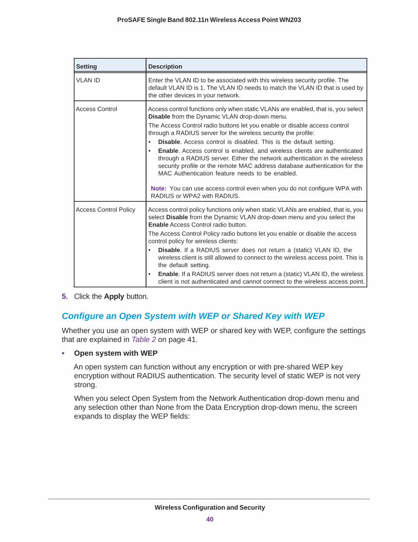
Configure an Open System with WEP or Shared Key with WEPWhether you use an open system with WEP or shared key with WEP, configure the settings that are explained in Table 2 on page 41.
• Open system with WEP
An open system can function without any encryption or with pre-shared WEP key encryption without RADIUS authentication. The security level of static WEP is not very strong.
When you select Open System from the Network Authentication drop-down menu and any selection other than None from the Data Encryption drop-down menu, the screen expands to display the WEP fields:
VLAN ID Enter the VLAN ID to be associated with this wireless security profile. The default VLAN ID is 1. The VLAN ID needs to match the VLAN ID that is used by the other devices in your network.
Access Control Access control functions only when static VLANs are enabled, that is, you select Disable from the Dynamic VLAN drop-down menu. The Access Control radio buttons let you enable or disable access control through a RADIUS server for the wireless security the profile:• Disable. Access control is disabled. This is the default setting.• Enable. Access control is enabled, and wireless clients are authenticated
through a RADIUS server. Either the network authentication in the wireless security profile or the remote MAC address database authentication for the MAC Authentication feature needs to be enabled.
Note: You can use access control even when you do not configure WPA with RADIUS or WPA2 with RADIUS.
Access Control Policy Access control policy functions only when static VLANs are enabled, that is, you select Disable from the Dynamic VLAN drop-down menu and you select the Enable Access Control radio button.The Access Control Policy radio buttons let you enable or disable the access control policy for wireless clients:• Disable. If a RADIUS server does not return a (static) VLAN ID, the
wireless client is still allowed to connect to the wireless access point. This is the default setting.
• Enable. If a RADIUS server does not return a (static) VLAN ID, the wireless client is not authenticated and cannot connect to the wireless access point.
Setting Description
Wireless Configuration and Security
40

ProSAFE Single Band 802.11n Wireless Access Point WN203
Figure 7. Open system with WEP
• Shared key with WEP
Shared key provides pre-shared WEP key encryption without RADIUS authentication. The security level of static WEP is not very strong. When you select Shared Key from the Network Authentication drop-down menu, the screen expands to display the WEP fields:
Figure 8. Shared key with WEP
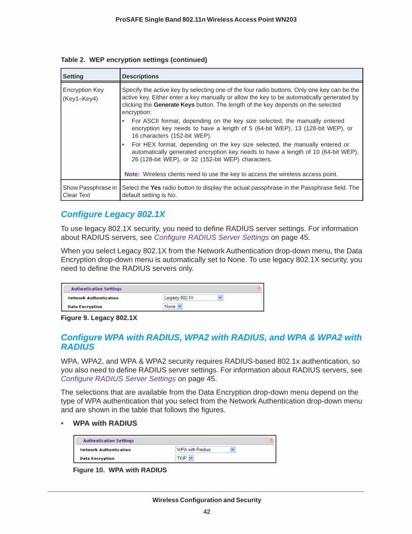
Table 2. WEP encryption settings
Setting Descriptions
Data Encryption Select the encryption key size from the drop-down menu:• 64-bit WEP. Standard WEP encryption, using 40/64-bit encryption.• 128-bit WEP. Standard WEP encryption, using 104/128-bit encryption.• 152-bit WEP. Proprietary WEP encryption mode, using 128+24 bit encryption. This
mode functions only with other wireless clients that support this mode.
Passphrase Enter a passphrase. The passphrase length needs to be between 8 and 63 characters (inclusive). The secret passphrase allows you to generate the keys automatically by clicking the Generate Keys button. The default passphrase is sharedsecret.You can display the actual passphrase by selecting the Show Passphrase in Clear Text Yes radio button.
Wireless Configuration and Security
41
ProSAFE Single Band 802.11n Wireless Access Point WN203
Configure Legacy 802.1XTo use legacy 802.1X security, you need to define RADIUS server settings. For information about RADIUS servers, see Configure RADIUS Server Settings on page 45.
When you select Legacy 802.1X from the Network Authentication drop-down menu, the Data Encryption drop-down menu is automatically set to None. To use legacy 802.1X security, you need to define the RADIUS servers only.
Figure 9. Legacy 802.1X
Configure WPA with RADIUS, WPA2 with RADIUS, and WPA & WPA2 with RADIUSWPA, WPA2, and WPA & WPA2 security requires RADIUS-based 802.1x authentication, so you also need to define RADIUS server settings. For information about RADIUS servers, see Configure RADIUS Server Settings on page 45.
The selections that are available from the Data Encryption drop-down menu depend on the type of WPA authentication that you select from the Network Authentication drop-down menu and are shown in the table that follows the figures.
• WPA with RADIUS
Figure 10. WPA with RADIUS
Encryption Key(Key1–Key4)
Specify the active key by selecting one of the four radio buttons. Only one key can be the active key. Either enter a key manually or allow the key to be automatically generated by clicking the Generate Keys button. The length of the key depends on the selected encryption:• For ASCII format, depending on the key size selected, the manually entered
encryption key needs to have a length of 5 (64-bit WEP), 13 (128-bit WEP), or 16 characters (152-bit WEP).
• For HEX format, depending on the key size selected, the manually entered or automatically generated encryption key needs to have a length of 10 (64-bit WEP), 26 (128-bit WEP), or 32 (152-bit WEP) characters.
Note: Wireless clients need to use the key to access the wireless access point.
Show Passphrase in Clear Text
Select the Yes radio button to display the actual passphrase in the Passphrase field. The default setting is No.
Table 2. WEP encryption settings (continued)
Setting Descriptions
Wireless Configuration and Security
42
ProSAFE Single Band 802.11n Wireless Access Point WN203
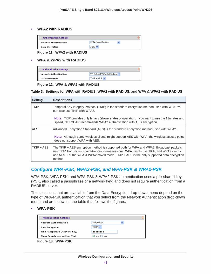
• WPA2 with RADIUS
Figure 11. WPA2 with RADIUS
• WPA & WPA2 with RADIUS
Figure 12. WPA & WPA2 with RADIUS
Table 3. Settings for WPA with RADIUS, WPA2 with RADIUS, and WPA & WPA2 with RADIUS
Setting Descriptions
TKIP Temporal Key Integrity Protocol (TKIP) is the standard encryption method used with WPA. You can also use TKIP with WPA2.
AES Advanced Encryption Standard (AES) is the standard encryption method used with WPA2.
TKIP + AES The TKIP + AES encryption method is supported both for WPA and WPA2. Broadcast packets use TKIP. For unicast (point-to-point) transmissions, WPA clients use TKIP, and WPA2 clients use AES. For the WPA & WPA2 mixed mode, TKIP + AES is the only supported data encryption method.
Configure WPA-PSK, WPA2-PSK, and WPA-PSK & WPA2-PSKWPA-PSK, WPA-PSK, and WPA-PSK & WPA2-PSK authentication uses a pre-shared key (PSK, also called a passphrase or a network key) and does not require authentication from a RADIUS server.
The selections that are available from the Data Encryption drop-down menu depend on the type of WPA-PSK authentication that you select from the Network Authentication drop-down menu and are shown in the table that follows the figures.
• WPA-PSK
Figure 13. WPA-PSK
Note: TKIP provides only legacy (slower) rates of operation. If you want to use the 11n rates and speed, NETGEAR recommends WPA2 authentication with AES encryption.
Note: Although some wireless clients might support AES with WPA, the wireless access point does not support WPA with AES.
Wireless Configuration and Security
43
ProSAFE Single Band 802.11n Wireless Access Point WN203
• WPA2-PSK
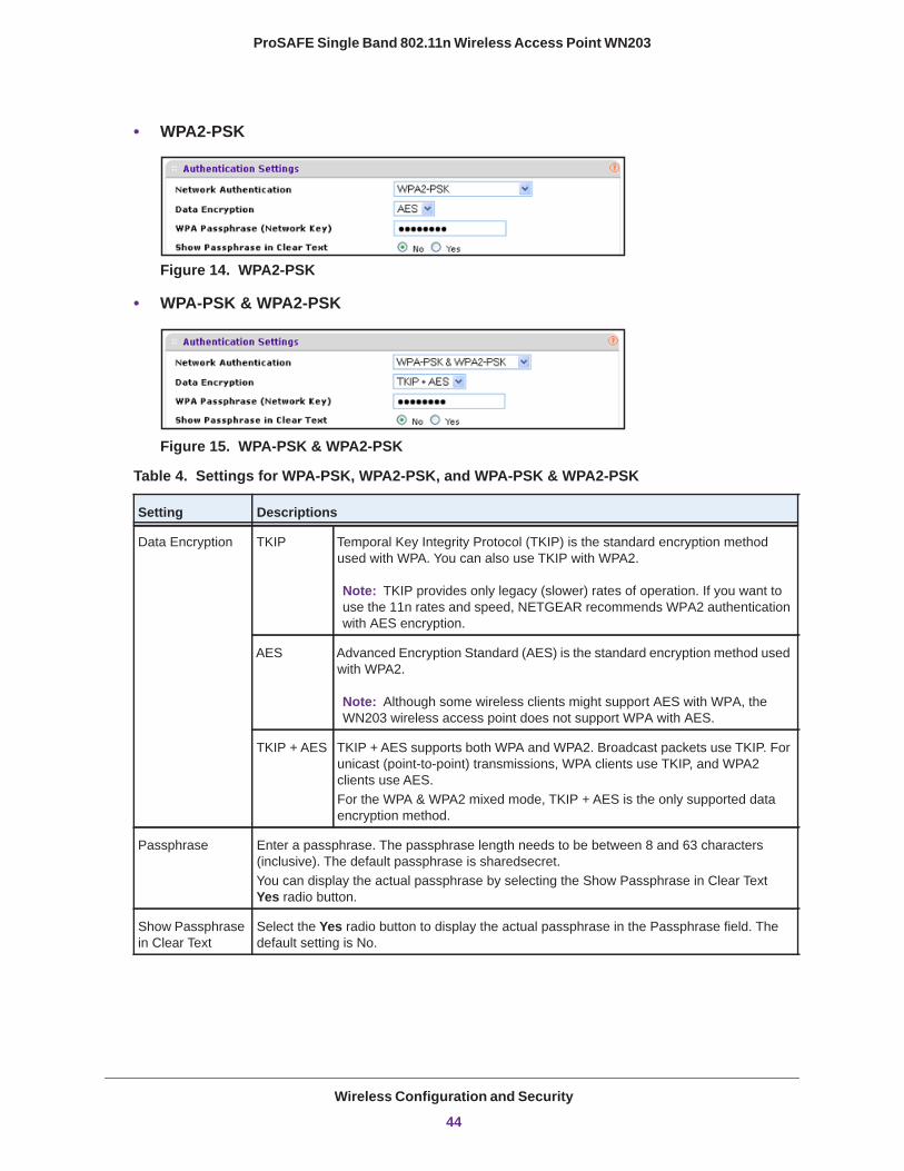
Figure 14. WPA2-PSK
• WPA-PSK & WPA2-PSK
Figure 15. WPA-PSK & WPA2-PSK
Table 4. Settings for WPA-PSK, WPA2-PSK, and WPA-PSK & WPA2-PSK
Setting Descriptions
Data Encryption TKIP Temporal Key Integrity Protocol (TKIP) is the standard encryption method used with WPA. You can also use TKIP with WPA2.
AES Advanced Encryption Standard (AES) is the standard encryption method used with WPA2.
TKIP + AES TKIP + AES supports both WPA and WPA2. Broadcast packets use TKIP. For unicast (point-to-point) transmissions, WPA clients use TKIP, and WPA2 clients use AES.For the WPA & WPA2 mixed mode, TKIP + AES is the only supported data encryption method.
Passphrase Enter a passphrase. The passphrase length needs to be between 8 and 63 characters (inclusive). The default passphrase is sharedsecret.You can display the actual passphrase by selecting the Show Passphrase in Clear Text Yes radio button.
Show Passphrase in Clear Text
Select the Yes radio button to display the actual passphrase in the Passphrase field. The default setting is No.
Note: TKIP provides only legacy (slower) rates of operation. If you want to use the 11n rates and speed, NETGEAR recommends WPA2 authentication with AES encryption.
Note: Although some wireless clients might support AES with WPA, the WN203 wireless access point does not support WPA with AES.
Wireless Configuration and Security
44
ProSAFE Single Band 802.11n Wireless Access Point WN203
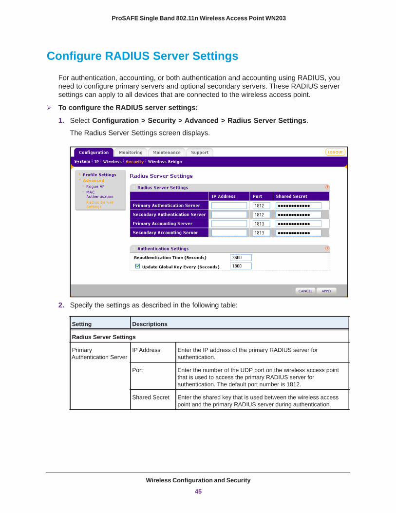
Configure RADIUS Server Settings
For authentication, accounting, or both authentication and accounting using RADIUS, you need to configure primary servers and optional secondary servers. These RADIUS server settings can apply to all devices that are connected to the wireless access point.
To configure the RADIUS server settings:
1. Select Configuration > Security > Advanced > Radius Server Settings. The Radius Server Settings screen displays.
2. Specify the settings as described in the following table:
Setting Descriptions
Radius Server Settings
Primary Authentication Server
IP Address Enter the IP address of the primary RADIUS server for authentication.
Port Enter the number of the UDP port on the wireless access point that is used to access the primary RADIUS server for authentication. The default port number is 1812.
Shared Secret Enter the shared key that is used between the wireless access point and the primary RADIUS server during authentication.
Wireless Configuration and Security
45
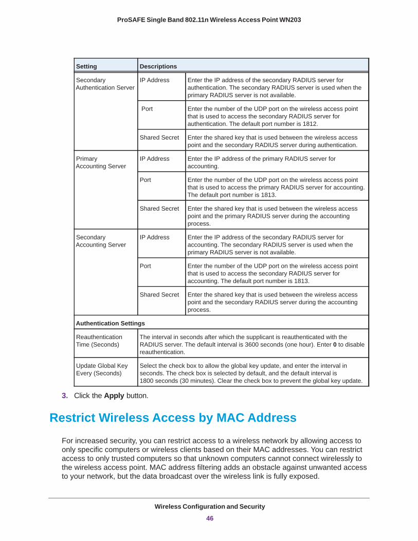
ProSAFE Single Band 802.11n Wireless Access Point WN203
3. Click the Apply button.
Restrict Wireless Access by MAC Address
For increased security, you can restrict access to a wireless network by allowing access to only specific computers or wireless clients based on their MAC addresses. You can restrict access to only trusted computers so that unknown computers cannot connect wirelessly to the wireless access point. MAC address filtering adds an obstacle against unwanted access to your network, but the data broadcast over the wireless link is fully exposed.
Secondary Authentication Server
IP Address Enter the IP address of the secondary RADIUS server for authentication. The secondary RADIUS server is used when the primary RADIUS server is not available.
Port Enter the number of the UDP port on the wireless access point that is used to access the secondary RADIUS server for authentication. The default port number is 1812.
Shared Secret Enter the shared key that is used between the wireless access point and the secondary RADIUS server during authentication.
Primary Accounting Server
IP Address Enter the IP address of the primary RADIUS server for accounting.
Port Enter the number of the UDP port on the wireless access point that is used to access the primary RADIUS server for accounting. The default port number is 1813.
Shared Secret Enter the shared key that is used between the wireless access point and the primary RADIUS server during the accounting process.
Secondary Accounting Server
IP Address Enter the IP address of the secondary RADIUS server for accounting. The secondary RADIUS server is used when the primary RADIUS server is not available.
Port Enter the number of the UDP port on the wireless access point that is used to access the secondary RADIUS server for accounting. The default port number is 1813.
Shared Secret Enter the shared key that is used between the wireless access point and the secondary RADIUS server during the accounting process.
Authentication Settings
Reauthentication Time (Seconds)
The interval in seconds after which the supplicant is reauthenticated with the RADIUS server. The default interval is 3600 seconds (one hour). Enter 0 to disable reauthentication.
Update Global Key Every (Seconds)
Select the check box to allow the global key update, and enter the interval in seconds. The check box is selected by default, and the default interval is 1800 seconds (30 minutes). Clear the check box to prevent the global key update.
Setting Descriptions
Wireless Configuration and Security
46
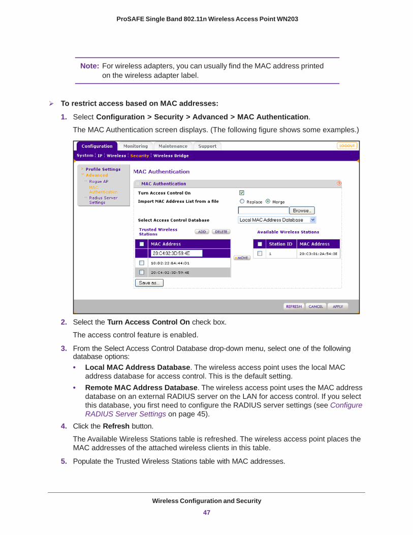
ProSAFE Single Band 802.11n Wireless Access Point WN203
Note: For wireless adapters, you can usually find the MAC address printed on the wireless adapter label.
To restrict access based on MAC addresses:
1. Select Configuration > Security > Advanced > MAC Authentication. The MAC Authentication screen displays. (The following figure shows some examples.)
2. Select the Turn Access Control On check box.
The access control feature is enabled.
3. From the Select Access Control Database drop-down menu, select one of the following database options:• Local MAC Address Database. The wireless access point uses the local MAC
address database for access control. This is the default setting.• Remote MAC Address Database. The wireless access point uses the MAC address
database on an external RADIUS server on the LAN for access control. If you select this database, you first need to configure the RADIUS server settings (see Configure RADIUS Server Settings on page 45).
4. Click the Refresh button.
The Available Wireless Stations table is refreshed. The wireless access point places the MAC addresses of the attached wireless clients in this table.
5. Populate the Trusted Wireless Stations table with MAC addresses.
Wireless Configuration and Security
47
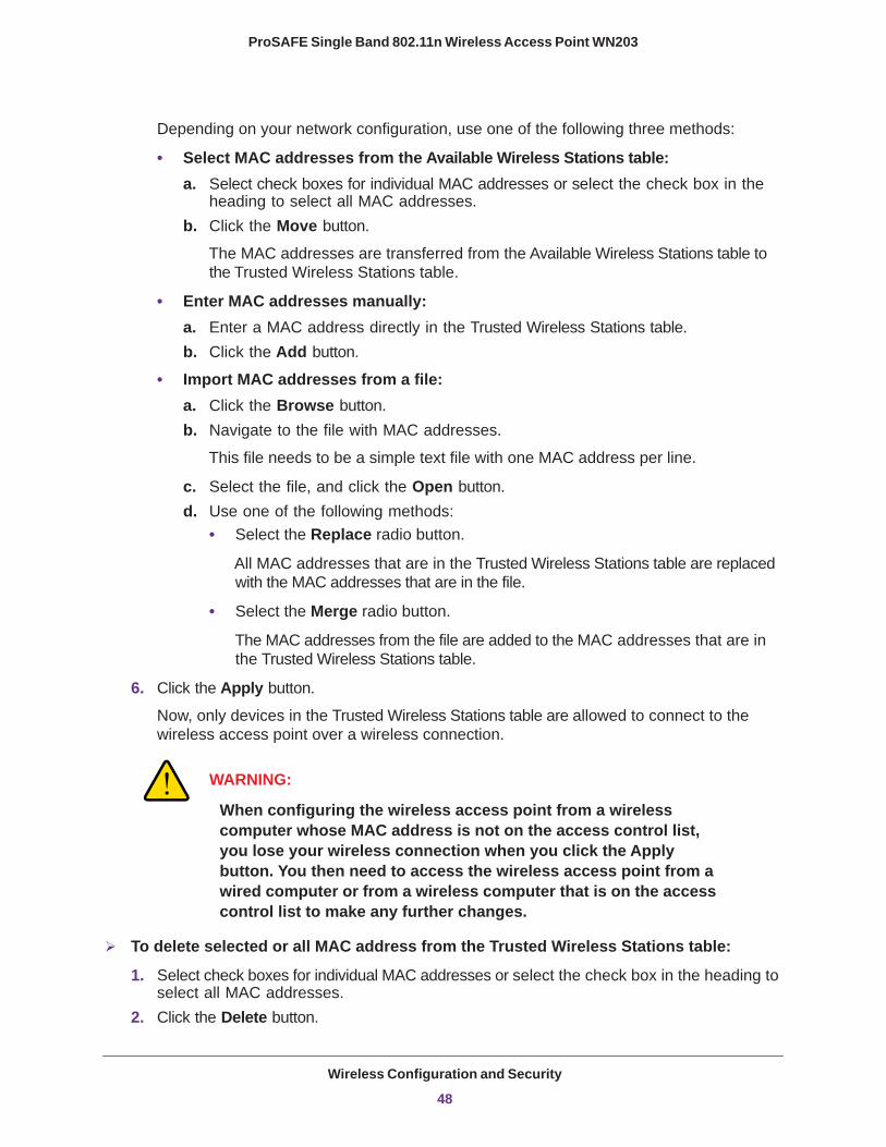
ProSAFE Single Band 802.11n Wireless Access Point WN203
Depending on your network configuration, use one of the following three methods:
• Select MAC addresses from the Available Wireless Stations table:a. Select check boxes for individual MAC addresses or select the check box in the
heading to select all MAC addresses.b. Click the Move button.
The MAC addresses are transferred from the Available Wireless Stations table to the Trusted Wireless Stations table.
• Enter MAC addresses manually:a. Enter a MAC address directly in the Trusted Wireless Stations table.b. Click the Add button.
• Import MAC addresses from a file:a. Click the Browse button.b. Navigate to the file with MAC addresses.
This file needs to be a simple text file with one MAC address per line.
c. Select the file, and click the Open button.d. Use one of the following methods:
• Select the Replace radio button.
All MAC addresses that are in the Trusted Wireless Stations table are replaced with the MAC addresses that are in the file.
• Select the Merge radio button.
The MAC addresses from the file are added to the MAC addresses that are in the Trusted Wireless Stations table.
6. Click the Apply button.
Now, only devices in the Trusted Wireless Stations table are allowed to connect to the wireless access point over a wireless connection.
WARNING:
When configuring the wireless access point from a wireless computer whose MAC address is not on the access control list, you lose your wireless connection when you click the Apply button. You then need to access the wireless access point from a wired computer or from a wireless computer that is on the access control list to make any further changes.
To delete selected or all MAC address from the Trusted Wireless Stations table:
1. Select check boxes for individual MAC addresses or select the check box in the heading to select all MAC addresses.
2. Click the Delete button.
Wireless Configuration and Security
48
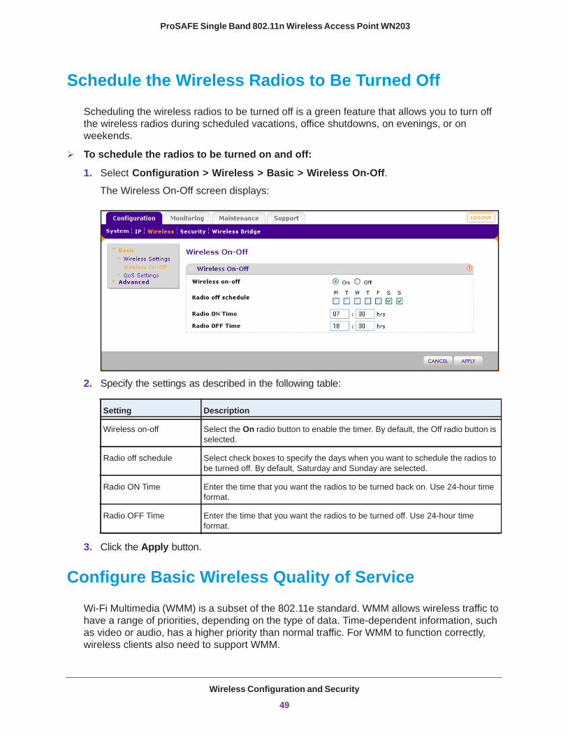
ProSAFE Single Band 802.11n Wireless Access Point WN203
Schedule the Wireless Radios to Be Turned Off
Scheduling the wireless radios to be turned off is a green feature that allows you to turn off the wireless radios during scheduled vacations, office shutdowns, on evenings, or on weekends.
To schedule the radios to be turned on and off:
1. Select Configuration > Wireless > Basic > Wireless On-Off. The Wireless On-Off screen displays:
2. Specify the settings as described in the following table:
Setting Description
Wireless on-off Select the On radio button to enable the timer. By default, the Off radio button is selected.
Radio off schedule Select check boxes to specify the days when you want to schedule the radios to be turned off. By default, Saturday and Sunday are selected.
Radio ON Time Enter the time that you want the radios to be turned back on. Use 24-hour time format.
Radio OFF Time Enter the time that you want the radios to be turned off. Use 24-hour time format.
3. Click the Apply button.
Configure Basic Wireless Quality of Service
Wi-Fi Multimedia (WMM) is a subset of the 802.11e standard. WMM allows wireless traffic to have a range of priorities, depending on the type of data. Time-dependent information, such as video or audio, has a higher priority than normal traffic. For WMM to function correctly, wireless clients also need to support WMM.
Wireless Configuration and Security
49
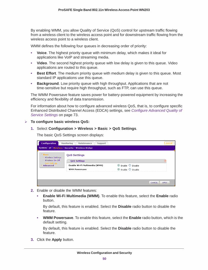
ProSAFE Single Band 802.11n Wireless Access Point WN203
By enabling WMM, you allow Quality of Service (QoS) control for upstream traffic flowing from a wireless client to the wireless access point and for downstream traffic flowing from the wireless access point to a wireless client.
WMM defines the following four queues in decreasing order of priority:
• Voice. The highest priority queue with minimum delay, which makes it ideal for applications like VoIP and streaming media.
• Video. The second highest priority queue with low delay is given to this queue. Video applications are routed to this queue.
• Best Effort. The medium priority queue with medium delay is given to this queue. Most standard IP applications use this queue.
• Background. Low priority queue with high throughput. Applications that are not time-sensitive but require high throughput, such as FTP, can use this queue.
The WMM Powersave feature saves power for battery-powered equipment by increasing the efficiency and flexibility of data transmission.
For information about how to configure advanced wireless QoS, that is, to configure specific Enhanced Distributed Channel Access (EDCA) settings, see Configure Advanced Quality of Service Settings on page 73.
To configure basic wireless QoS:
1. Select Configuration > Wireless > Basic > QoS Settings.
The basic QoS Settings screen displays:
2. Enable or disable the WMM features:• Enable Wi-Fi Multimedia (WMM). To enable this feature, select the Enable radio
button.By default, this feature is enabled. Select the Disable radio button to disable the feature.
• WMM Powersave. To enable this feature, select the Enable radio button, which is the default setting. By default, this feature is enabled. Select the Disable radio button to disable the feature.
3. Click the Apply button.
Wireless Configuration and Security
50
4
4. ManagementThis chapter describes how to use the management features of the wireless access point. The chapter includes the following sections:
• Enable Remote Management• Upgrade the Wireless Access Point Software• Manage the Configuration File or Reset to Factory Default• Change the Administrator Password• Enable the Syslog Option• Enable Rogue AP Detection and Monitor Access Points
51
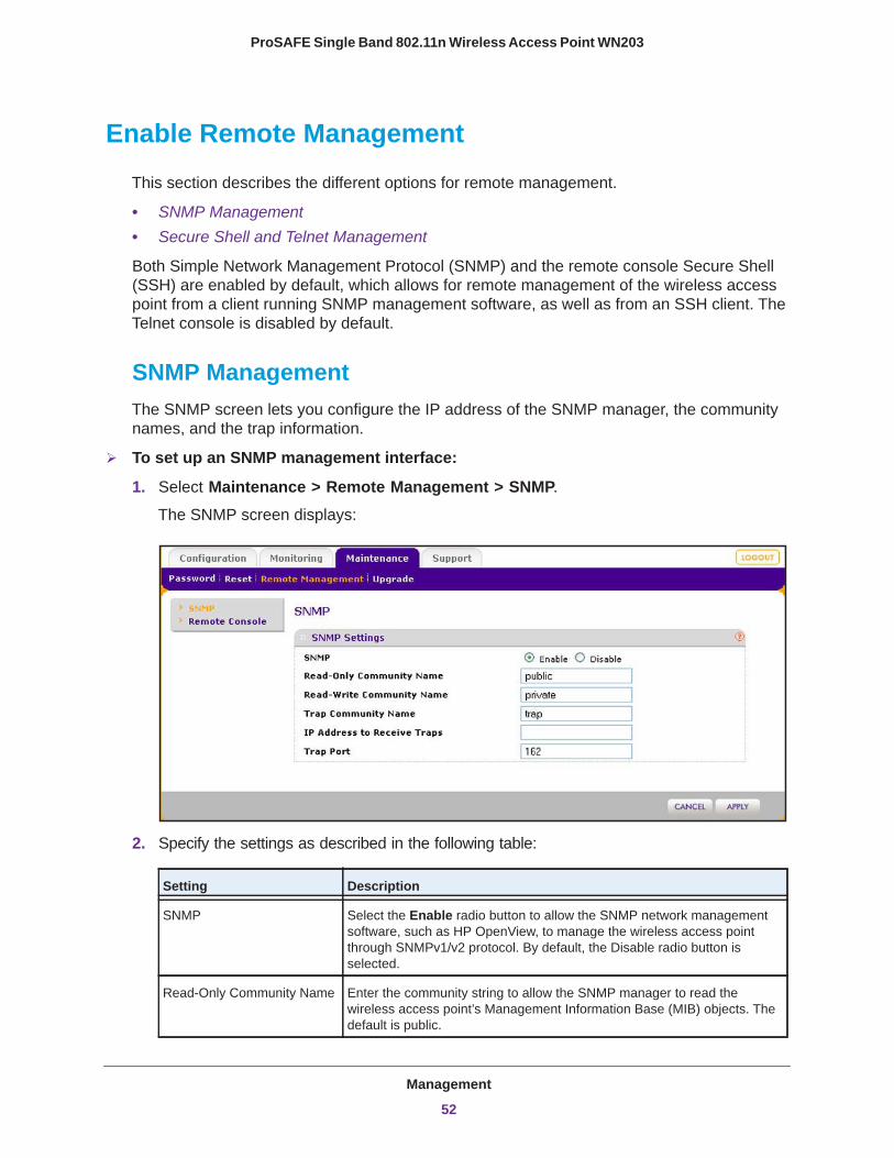
ProSAFE Single Band 802.11n Wireless Access Point WN203
Enable Remote Management
This section describes the different options for remote management.
• SNMP Management• Secure Shell and Telnet Management
Both Simple Network Management Protocol (SNMP) and the remote console Secure Shell (SSH) are enabled by default, which allows for remote management of the wireless access point from a client running SNMP management software, as well as from an SSH client. The Telnet console is disabled by default.
SNMP ManagementThe SNMP screen lets you configure the IP address of the SNMP manager, the community names, and the trap information.
To set up an SNMP management interface:
1. Select Maintenance > Remote Management > SNMP.
The SNMP screen displays:
2. Specify the settings as described in the following table:
Setting Description
SNMP Select the Enable radio button to allow the SNMP network management software, such as HP OpenView, to manage the wireless access point through SNMPv1/v2 protocol. By default, the Disable radio button is selected.
Read-Only Community Name Enter the community string to allow the SNMP manager to read the wireless access point’s Management Information Base (MIB) objects. The default is public.
Management
52
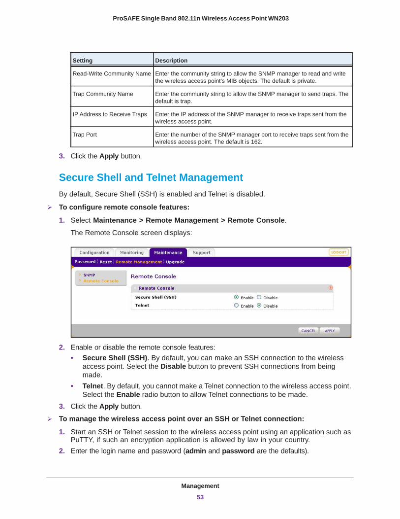
ProSAFE Single Band 802.11n Wireless Access Point WN203
3. Click the Apply button.
Secure Shell and Telnet ManagementBy default, Secure Shell (SSH) is enabled and Telnet is disabled.
To configure remote console features:
1. Select Maintenance > Remote Management > Remote Console.
The Remote Console screen displays:
2. Enable or disable the remote console features:• Secure Shell (SSH). By default, you can make an SSH connection to the wireless
access point. Select the Disable button to prevent SSH connections from being made.
• Telnet. By default, you cannot make a Telnet connection to the wireless access point. Select the Enable radio button to allow Telnet connections to be made.
3. Click the Apply button.
To manage the wireless access point over an SSH or Telnet connection:
1. Start an SSH or Telnet session to the wireless access point using an application such as PuTTY, if such an encryption application is allowed by law in your country.
2. Enter the login name and password (admin and password are the defaults).
Read-Write Community Name Enter the community string to allow the SNMP manager to read and write the wireless access point’s MIB objects. The default is private.
Trap Community Name Enter the community string to allow the SNMP manager to send traps. The default is trap.
IP Address to Receive Traps Enter the IP address of the SNMP manager to receive traps sent from the wireless access point.
Trap Port Enter the number of the SNMP manager port to receive traps sent from the wireless access point. The default is 162.
Setting Description
Management
53
ProSAFE Single Band 802.11n Wireless Access Point WN203
After successful login, the > prompt displays, preceded by the name of the wireless access point.
3. Enter the CLI commands that you want to use.
You can enter ? to display the available CLI commands. The CLI commands are also listed in Appendix B, Command-Line Reference.
Upgrade the Wireless Access Point Software
The software of the wireless access point is stored in flash memory and can be upgraded as NETGEAR releases new software. You can download upgrade files from the NETGEAR website. If the upgrade file is compressed (.zip file or .rar file), you first need to extract the image file (.bin file) before sending it to the wireless access point. You can send the upgrade file using your browser. The following sections describe the two methods that are available to perform a software upgrade:
• Web Browser Upgrade Procedure • TFTP Server Upgrade Procedure
Note: The web browser that you use to upload new firmware into the wireless access point needs to support HTTP uploads. Use a browser such as Microsoft Internet Explorer 8.0 or later, or Mozilla Firefox 18.0 or later.
Note: You cannot perform the software upgrade from a computer that is connected to the wireless access point over a wireless link. You need to use a computer that is connected to the wireless access point over an Ethernet cable.
WARNING:
When uploading software to the wireless access point, do not interrupt the web browser by closing the window, clicking a link, or loading a new page. If the browser is interrupted, the upload might fail, corrupt the software, and render the wireless access point inoperable.
Management
54
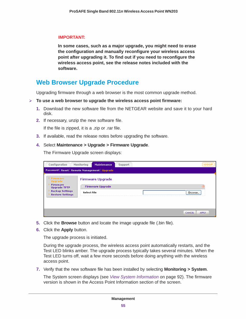
ProSAFE Single Band 802.11n Wireless Access Point WN203
IMPORTANT:
In some cases, such as a major upgrade, you might need to erase the configuration and manually reconfigure your wireless access point after upgrading it. To find out if you need to reconfigure the wireless access point, see the release notes included with the software.
Web Browser Upgrade ProcedureUpgrading firmware through a web browser is the most common upgrade method.
To use a web browser to upgrade the wireless access point firmware:
1. Download the new software file from the NETGEAR website and save it to your hard disk.
2. If necessary, unzip the new software file.
If the file is zipped, it is a .zip or .rar file.
3. If available, read the release notes before upgrading the software.
4. Select Maintenance > Upgrade > Firmware Upgrade.
The Firmware Upgrade screen displays:
5. Click the Browse button and locate the image upgrade file (.bin file). 6. Click the Apply button.
The upgrade process is initiated.
During the upgrade process, the wireless access point automatically restarts, and the Test LED blinks amber. The upgrade process typically takes several minutes. When the Test LED turns off, wait a few more seconds before doing anything with the wireless access point.
7. Verify that the new software file has been installed by selecting Monitoring > System.
The System screen displays (see View System Information on page 92). The firmware version is shown in the Access Point Information section of the screen.
Management
55

ProSAFE Single Band 802.11n Wireless Access Point WN203
TFTP Server Upgrade ProcedureTo use this method, you need to have a TFTP server set up.
To use a TFTP server to upgrade the wireless access point firmware:
1. Download the new software file from the NETGEAR website and save it to your hard disk.
2. Place the software file in your TFTP server location. (You do not need to unzip the file.)3. If available, read the release notes before upgrading the software.4. Select Maintenance > Upgrade > Firmware Upgrade TFTP.
The Firmware Upgrade TFTP screen displays:
5. Specify the following information:• Firmware File Name. The name of the unzipped software file.• TFTP Server IP. The IP address of your TFTP server.
6. Click the Apply button.
The upgrade process is initiated.
During the upgrade process, the wireless access point automatically restarts, and the Test LED blinks amber. The upgrade process typically takes several minutes. When the Test LED turns off, wait a few more seconds before doing anything with the wireless access point.
7. Verify that the new software file has been installed by selecting Monitoring > System.
The System screen displays (see View System Information on page 92). The firmware version is shown in the Access Point Information section of the screen.
Management
56
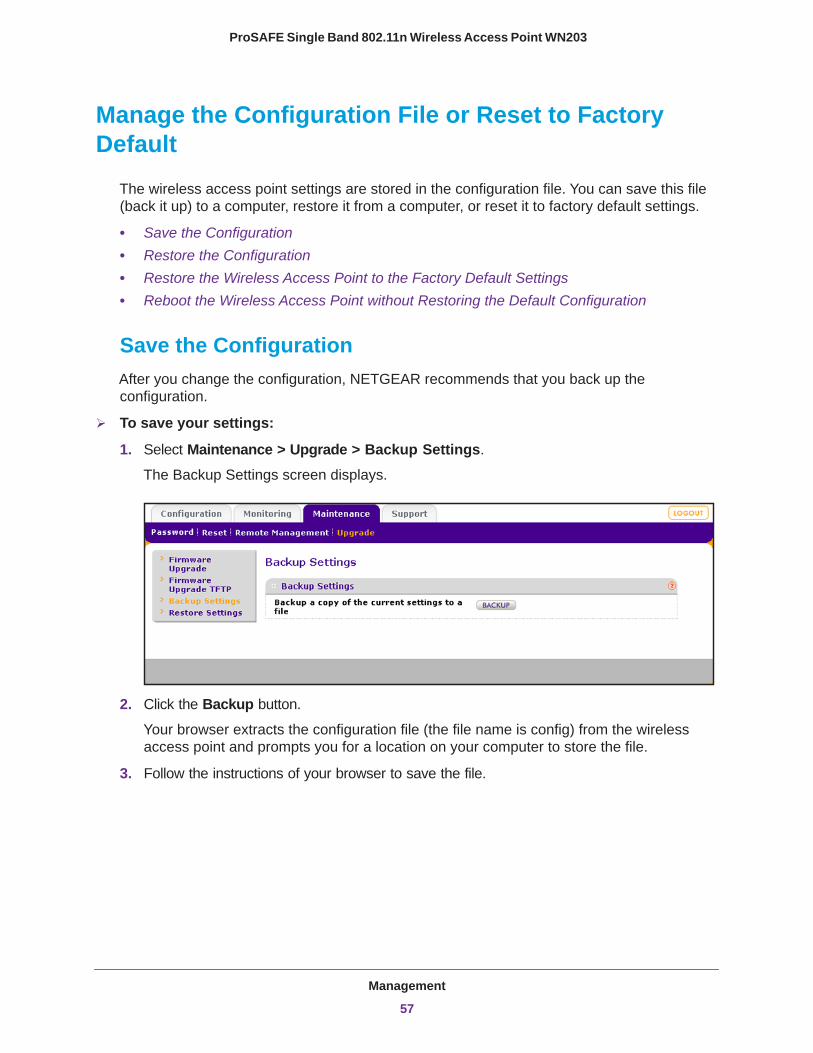
ProSAFE Single Band 802.11n Wireless Access Point WN203
Manage the Configuration File or Reset to Factory Default
The wireless access point settings are stored in the configuration file. You can save this file (back it up) to a computer, restore it from a computer, or reset it to factory default settings.
• Save the Configuration• Restore the Configuration• Restore the Wireless Access Point to the Factory Default Settings• Reboot the Wireless Access Point without Restoring the Default Configuration
Save the ConfigurationAfter you change the configuration, NETGEAR recommends that you back up the configuration.
To save your settings:
1. Select Maintenance > Upgrade > Backup Settings.
The Backup Settings screen displays.
2. Click the Backup button.
Your browser extracts the configuration file (the file name is config) from the wireless access point and prompts you for a location on your computer to store the file.
3. Follow the instructions of your browser to save the file.
Management
57
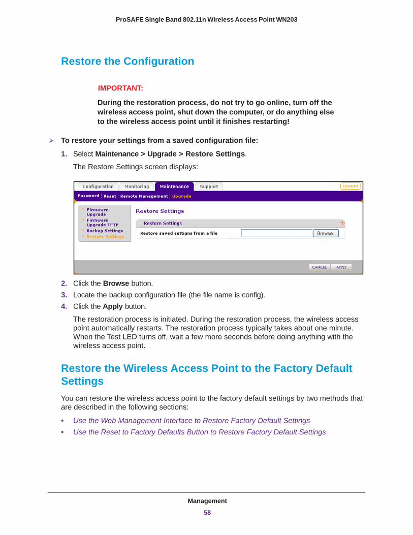
ProSAFE Single Band 802.11n Wireless Access Point WN203
Restore the Configuration
IMPORTANT:
During the restoration process, do not try to go online, turn off the wireless access point, shut down the computer, or do anything else to the wireless access point until it finishes restarting!
To restore your settings from a saved configuration file:
1. Select Maintenance > Upgrade > Restore Settings.
The Restore Settings screen displays:
2. Click the Browse button.3. Locate the backup configuration file (the file name is config).4. Click the Apply button.
The restoration process is initiated. During the restoration process, the wireless access point automatically restarts. The restoration process typically takes about one minute. When the Test LED turns off, wait a few more seconds before doing anything with the wireless access point.
Restore the Wireless Access Point to the Factory Default SettingsYou can restore the wireless access point to the factory default settings by two methods that are described in the following sections:
• Use the Web Management Interface to Restore Factory Default Settings• Use the Reset to Factory Defaults Button to Restore Factory Default Settings
Management
58
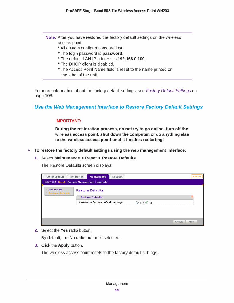
ProSAFE Single Band 802.11n Wireless Access Point WN203
Note: After you have restored the factory default settings on the wireless access point: * All custom configurations are lost. * The login password is password. * The default LAN IP address is 192.168.0.100. * The DHCP client is disabled. * The Access Point Name field is reset to the name printed on the label of the unit.
For more information about the factory default settings, see Factory Default Settings on page 108.
Use the Web Management Interface to Restore Factory Default Settings
IMPORTANT:
During the restoration process, do not try to go online, turn off the wireless access point, shut down the computer, or do anything else to the wireless access point until it finishes restarting!
To restore the factory default settings using the web management interface:
1. Select Maintenance > Reset > Restore Defaults.
The Restore Defaults screen displays:
2. Select the Yes radio button.
By default, the No radio button is selected.
3. Click the Apply button.
The wireless access point resets to the factory default settings.
Management
59

ProSAFE Single Band 802.11n Wireless Access Point WN203
During the restoration process, the wireless access point automatically restarts. The restoration process typically takes about one minute. When the Test LED turns off, wait a few more seconds before doing anything with the wireless access point.
Use the Reset to Factory Defaults Button to Restore Factory Default SettingsTo restore the factory default settings when you do not know the login user name, login password, or IP address, you need to use the Reset to Factory Defaults button on the bottom panel of the wireless access point (see Figure 3 on page 13).
To restore the factory default settings using the Reset to Factory Defaults button:
1. Using a sharp object, press and hold the Reset to Factory Defaults button for about 10 seconds to reset the wireless access point to factory default settings.
Note: Pressing the Reset to Factory Defaults button for a few seconds simply causes the wireless access point to reboot.
2. Release the Reset to Factory Defaults button.
During the restoration process, the wireless access point automatically restarts. The restoration process typically takes about one minute. When the Test LED turns off, wait a few more seconds before doing anything with the wireless access point.
Reboot the Wireless Access Point without Restoring the Default ConfigurationIf you do not have physical access to the wireless access point to switch it off and on again, you can use the software to reboot the wireless access point.
To reboot the wireless access point:
1. Select Maintenance > Reset > Reboot AP.
The Reboot AP screen displays:
Management
60
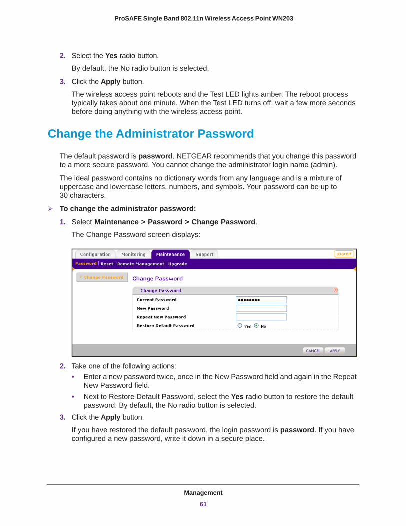
ProSAFE Single Band 802.11n Wireless Access Point WN203
2. Select the Yes radio button.
By default, the No radio button is selected.
3. Click the Apply button.
The wireless access point reboots and the Test LED lights amber. The reboot process typically takes about one minute. When the Test LED turns off, wait a few more seconds before doing anything with the wireless access point.
Change the Administrator Password
The default password is password. NETGEAR recommends that you change this password to a more secure password. You cannot change the administrator login name (admin).
The ideal password contains no dictionary words from any language and is a mixture of uppercase and lowercase letters, numbers, and symbols. Your password can be up to 30 characters.
To change the administrator password:
1. Select Maintenance > Password > Change Password.
The Change Password screen displays:
2. Take one of the following actions:• Enter a new password twice, once in the New Password field and again in the Repeat
New Password field.• Next to Restore Default Password, select the Yes radio button to restore the default
password. By default, the No radio button is selected.3. Click the Apply button.
If you have restored the default password, the login password is password. If you have configured a new password, write it down in a secure place.
Management
61
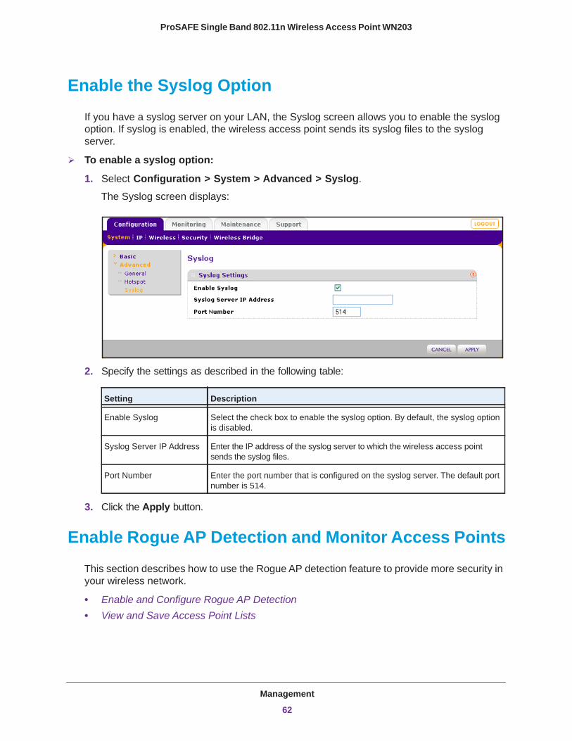
ProSAFE Single Band 802.11n Wireless Access Point WN203
Enable the Syslog Option
If you have a syslog server on your LAN, the Syslog screen allows you to enable the syslog option. If syslog is enabled, the wireless access point sends its syslog files to the syslog server.
To enable a syslog option:
1. Select Configuration > System > Advanced > Syslog.
The Syslog screen displays:
2. Specify the settings as described in the following table:
Setting Description
Enable Syslog Select the check box to enable the syslog option. By default, the syslog option is disabled.
Syslog Server IP Address Enter the IP address of the syslog server to which the wireless access point sends the syslog files.
Port Number Enter the port number that is configured on the syslog server. The default port number is 514.
3. Click the Apply button.
Enable Rogue AP Detection and Monitor Access Points
This section describes how to use the Rogue AP detection feature to provide more security in your wireless network.
• Enable and Configure Rogue AP Detection• View and Save Access Point Lists
Management
62
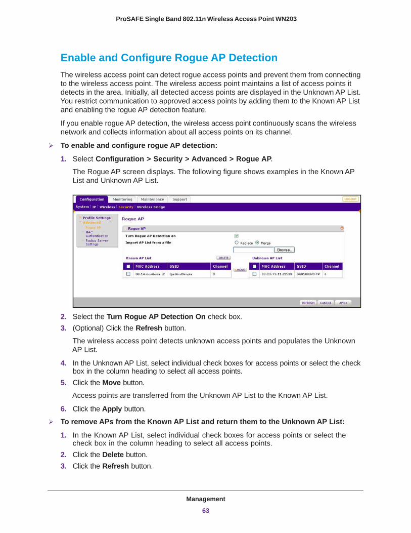
ProSAFE Single Band 802.11n Wireless Access Point WN203
Enable and Configure Rogue AP DetectionThe wireless access point can detect rogue access points and prevent them from connecting to the wireless access point. The wireless access point maintains a list of access points it detects in the area. Initially, all detected access points are displayed in the Unknown AP List. You restrict communication to approved access points by adding them to the Known AP List and enabling the rogue AP detection feature.
If you enable rogue AP detection, the wireless access point continuously scans the wireless network and collects information about all access points on its channel.
To enable and configure rogue AP detection:
1. Select Configuration > Security > Advanced > Rogue AP.
The Rogue AP screen displays. The following figure shows examples in the Known AP List and Unknown AP List.
2. Select the Turn Rogue AP Detection On check box.3. (Optional) Click the Refresh button.
The wireless access point detects unknown access points and populates the Unknown AP List.
4. In the Unknown AP List, select individual check boxes for access points or select the check box in the column heading to select all access points.
5. Click the Move button.
Access points are transferred from the Unknown AP List to the Known AP List.
6. Click the Apply button.
To remove APs from the Known AP List and return them to the Unknown AP List:
1. In the Known AP List, select individual check boxes for access points or select the check box in the column heading to select all access points.
2. Click the Delete button.3. Click the Refresh button.
Management
63
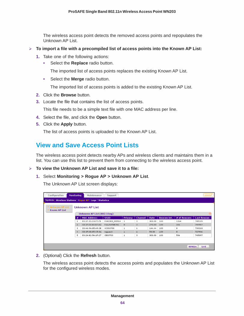
ProSAFE Single Band 802.11n Wireless Access Point WN203
The wireless access point detects the removed access points and repopulates the Unknown AP List.
To import a file with a precompiled list of access points into the Known AP List:
1. Take one of the following actions:• Select the Replace radio button.
The imported list of access points replaces the existing Known AP List.
• Select the Merge radio button.
The imported list of access points is added to the existing Known AP List.
2. Click the Browse button.3. Locate the file that contains the list of access points.
This file needs to be a simple text file with one MAC address per line.
4. Select the file, and click the Open button.5. Click the Apply button.
The list of access points is uploaded to the Known AP List.
View and Save Access Point ListsThe wireless access point detects nearby APs and wireless clients and maintains them in a list. You can use this list to prevent them from connecting to the wireless access point.
To view the Unknown AP List and save it to a file:
1. Select Monitoring > Rogue AP > Unknown AP List. The Unknown AP List screen displays:
2. (Optional) Click the Refresh button.
The wireless access point detects the access points and populates the Unknown AP List for the configured wireless modes.
Management
64

ProSAFE Single Band 802.11n Wireless Access Point WN203
The following table explains the fields of the Unknown AP List screen:
Setting Description
MAC Address The MAC address of the unknown AP.
SSID The SSID that the unknown AP is using.
Privacy Indicates whether security is enabled (1 means enabled; 0 means disabled).
Channel The channel that the unknown AP is using.
Rate The transmit data rate in Mbps of the unknown the AP.
Beacon Int. The interval for each beacon transmission in ms.
# of Beacons The number of beacons transmitted by the unknown AP that the wireless access point has detected.
Last Seen The time stamp that indicates the time when the most recent beacon was detected.
3. Click the Save button.
Export the list of unknown APs to a file. A window opens so you can browse to the location where you want to save the file. The default file name is macList.txt.
4. (Optional) After you have reviewed the list, import the saved list into the Known AP List on the Rogue AP screen (see Enable and Configure Rogue AP Detection on page 63).
To view the Known AP Lists and save it to a file:
1. Select Monitoring > Rogue AP > Known AP List. The Known AP List screen displays:
2. (Optional) Click the Refresh button.
The wireless access point detects the access points and populates the Known AP List for the configured wireless modes.
Management
65

ProSAFE Single Band 802.11n Wireless Access Point WN203
The following table explains the fields of the Known AP List screen:
Setting Description
MAC Address The MAC address of the known AP.
SSID The SSID that the known AP is using.
Channel The channel that the known AP is using.
3. Click the Save button.
Export the list of known APs to a file. A window opens so you can browse to the location where you want to save the file. The default file name is macList.txt.
Management
66
5
5. Advanced ConfigurationThis chapter describes how to configure the advanced features of the wireless access point. The chapter includes the following sections:
• Configure Spanning Tree Protocol and 802.1Q VLANs• Configure Hotspot Settings• Configure Advanced Wireless Settings• Configure Advanced Quality of Service Settings• Configure Wireless Bridging
67
ProSAFE Single Band 802.11n Wireless Access Point WN203
Configure Spanning Tree Protocol and 802.1Q VLANs
Spanning Tree Protocol (STP) provides network traffic optimization in locations where multiple wireless access points are active by preventing path redundancy. If you have more than one active wireless access point at your location, NETGEAR recommends that you enable STP.
The 802.1Q VLAN protocol on the wireless access point logically separates traffic on the same physical network:
• Untagged VLAN. When the wireless access point sends frames that are associated with the untagged VLAN from its Ethernet interface, those frames are untagged. When the wireless access point receives untagged frames over its Ethernet interface, those frames are assigned to the untagged VLAN.
Note: Use an untagged VLAN only if the hubs and switches on your LAN support the 802.1Q VLAN protocol. Likewise, change the untagged VLAN value only if the hubs and switches on your LAN support the 802.1Q VLAN protocol.
• Tagged VLAN. When you clear the Untagged VLAN check box, the wireless access point tags all frames that are sent from its Ethernet interface. Only incoming frames that are tagged with known VLAN IDs are accepted.
• Management VLAN. The management VLAN can be active only when the wireless access point functions as a point-to-point or point-to-multipoint bridge (see Configure Wireless Bridging on page 75). The management VLAN is used for managing traffic (Telnet, SNMP, and HTTP) to and from the wireless access point.
Frames belonging to the management VLAN are not given any 802.1Q header when they are sent over the trunk. If a port is in a single VLAN, it can be untagged. However, if the port is a member of multiple VLANs, it needs to be tagged.
WARNING:
Selecting the Untagged VLAN check box or changing the untagged VLAN value causes loss of IP connectivity if the hubs and switches on your LAN have not yet been configured with the corresponding VLAN.
Advanced Configuration
68

ProSAFE Single Band 802.11n Wireless Access Point WN203
To configure STP and VLANs:
1. Select Configuration > System > Advanced > General. The advanced General system settings screen displays:
2. Specify the settings as described in the following table:
Setting Description
Spanning Tree Protocol
Spanning Tree Protocol Select the Enable radio button to enable STP to prevent path redundancy. By default, the Disable radio button is selected.
802.1Q VLAN
Untagged VLAN Select the Untagged VLAN check box to configure one VLAN as an untagged VLAN. By default, the Untagged VLAN check box is selected.Specify a VLAN ID. The default VLAN ID is 1.
Management VLAN Specify an ID for the VLAN from which the wireless access point can be managed. The default VLAN ID is 1.
3. Click the Apply button.
Configure Hotspot Settings
If the wireless access point functions as a public access point and you want it to capture and redirect all HTTP requests (over TCP, port 80), set up a hotspot server to redirect the requests to the specified URL and manage the clients. For example, you can redirect HTTP requests to a web server for authentication, timing control, or advertising. A hotel might want all wireless connections to go to its server to start a billing transaction.
Note: If you configure the management VLAN ID as 0 (zero), the wireless access point can be managed over any VLAN, and frames that belong to the management VLAN are not tagged with an 802.1Q header when sent over the trunk.
Advanced Configuration
69
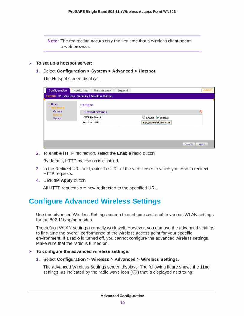
ProSAFE Single Band 802.11n Wireless Access Point WN203
Note: The redirection occurs only the first time that a wireless client opens a web browser.
To set up a hotspot server:
1. Select Configuration > System > Advanced > Hotspot. The Hotspot screen displays:
2. To enable HTTP redirection, select the Enable radio button.
By default, HTTP redirection is disabled.
3. In the Redirect URL field, enter the URL of the web server to which you wish to redirect HTTP requests.
4. Click the Apply button.
All HTTP requests are now redirected to the specified URL.
Configure Advanced Wireless Settings
Use the advanced Wireless Settings screen to configure and enable various WLAN settings for the 802.11b/bg/ng modes.
The default WLAN settings normally work well. However, you can use the advanced settings to fine-tune the overall performance of the wireless access point for your specific environment. If a radio is turned off, you cannot configure the advanced wireless settings. Make sure that the radio is turned on.
To configure the advanced wireless settings:
1. Select Configuration > Wireless > Advanced > Wireless Settings.
The advanced Wireless Settings screen displays. The following figure shows the 11ng settings, as indicated by the radio wave icon ( ) that is displayed next to ng:
Advanced Configuration
70
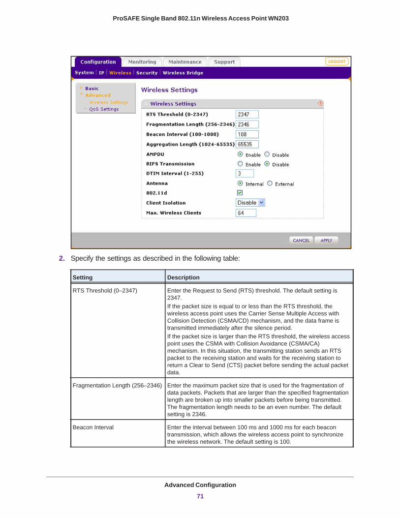
ProSAFE Single Band 802.11n Wireless Access Point WN203
2. Specify the settings as described in the following table:
Setting Description
RTS Threshold (0–2347) Enter the Request to Send (RTS) threshold. The default setting is 2347.If the packet size is equal to or less than the RTS threshold, the wireless access point uses the Carrier Sense Multiple Access with Collision Detection (CSMA/CD) mechanism, and the data frame is transmitted immediately after the silence period.If the packet size is larger than the RTS threshold, the wireless access point uses the CSMA with Collision Avoidance (CSMA/CA) mechanism. In this situation, the transmitting station sends an RTS packet to the receiving station and waits for the receiving station to return a Clear to Send (CTS) packet before sending the actual packet data.
Fragmentation Length (256–2346) Enter the maximum packet size that is used for the fragmentation of data packets. Packets that are larger than the specified fragmentation length are broken up into smaller packets before being transmitted. The fragmentation length needs to be an even number. The default setting is 2346.
Beacon Interval Enter the interval between 100 ms and 1000 ms for each beacon transmission, which allows the wireless access point to synchronize the wireless network. The default setting is 100.
Advanced Configuration
71
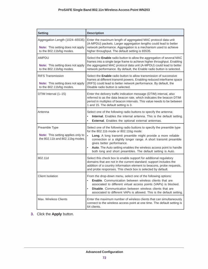
ProSAFE Single Band 802.11n Wireless Access Point WN203
3. Click the Apply button.
Aggregation Length (1024–65535)
Note: This setting does not apply to the 802.11b/bg modes.
Enter the maximum length of aggregated MAC protocol data unit (A-MPDU) packets. Larger aggregation lengths could lead to better network performance. Aggregation is a mechanism used to achieve higher throughput. The default setting is 65535.
AMPDU
Note: This setting does not apply to the 802.11b/bg modes.
Select the Enable radio button to allow the aggregation of several MAC frames into a single large frame to achieve higher throughput. Enabling the aggregated MAC protocol data unit (A-MPDU) could lead to better network performance. By default, the Enable radio button is selected.
RIFS Transmission
Note: This setting does not apply to the 802.11b/bg modes.
Select the Enable radio button to allow transmission of successive frames at different transmit powers. Enabling reduced interframe space (RIFS) could lead to better network performance. By default, the Disable radio button is selected.
DTIM Interval (1–15) Enter the delivery traffic indication message (DTIM) interval, also referred to as the data beacon rate, which indicates the beacon DTIM period in multiples of beacon intervals. This value needs to be between 1 and 15. The default setting is 3.
Antenna Select one of the following radio buttons to specify the antenna:• Internal. Enables the internal antenna. This is the default setting.• External. Enables the optional external antennas.
Preamble Type
Note: This setting applies only to the 802.11b and 802.11bg modes.
Select one of the following radio buttons to specify the preamble type for the 802.11b mode or 802.11bg mode:• Long. A long transmit preamble might provide a more reliable
connection or a slightly longer range. A short transmit preamble gives better performance.
• Auto. The Auto setting enables the wireless access point to handle both long and short preambles. The default setting is Auto.
802.11d Select this check box to enable support for additional regulatory domains that are not in the current standard; support includes the addition of a country information element to beacons, probe requests, and probe responses. This check box is selected by default.
Client Isolation From the drop-down menu, select one of the following options:• Enable. Communication between wireless clients that are
associated to different virtual access points (VAPs) is blocked.• Disable. Communication between wireless clients that are
associated to different VAPs is allowed. This is the default setting.
Max. Wireless Clients Enter the maximum number of wireless clients that can simultaneously connect to the wireless access point at one time. The default setting is 64 clients.
Setting Description
Advanced Configuration
72

ProSAFE Single Band 802.11n Wireless Access Point WN203
Configure Advanced Quality of Service Settings
For most networks, the default Quality of Service (QoS) queue settings work well. For information about how to configure basic QoS, see Configure Basic Wireless Quality of Service on page 49.
You can specify the settings on multiple queues for increased throughput and better performance of differentiated wireless traffic such as voice over IP (VoIP), other types of audio, video, and streaming media, as well as traditional IP data.
The advanced QoS options on the wireless access point are as follows:
• AP EDCA parameters. Specify the access point (AP) Enhanced Distributed Channel Access (EDCA) settings for different types of data transmitted from the wireless access point to wireless clients.
• Station EDCA parameters. Specify the station EDCA parameters for different types of data transmitted from the wireless clients to the wireless access point. If WMM is disabled, you cannot configure the Station EDCA parameters. (For information about how to enable WMM, see Configure Basic Wireless Quality of Service on page 49.)
When you configure the EDCA settings, the wireless access point can leverage existing information in the IP packet header that is related to the Type of Service (ToS). The wireless access point examines the ToS field in the headers of all packets that it processes. Based on the value in a packet’s ToS field, the wireless access point prioritizes the packet for transmission by assigning it to one of the queues. A different type of data is associated with each queue. You can configure how the wireless access point treats each queue.
The queues defined for different types of data transmitted from AP-to-station and station-to-AP are:
• Data 0 (Best Effort). Medium priority queue, medium throughput and delay. Most traditional IP data is sent to this queue.
• Data 1 (Background). Lowest priority queue, high throughput. Bulk data that requires maximum throughput and is not time-sensitive is sent to this queue (FTP data, for example).
• Data 2 (Video). Highest priority queue, minimum delay. Time-sensitive video data is automatically sent to this queue.
• Data 3 (Voice). Highest priority queue, minimum delay. Time-sensitive data such as VoIP and streaming media are automatically sent to this queue.
To configure advanced QoS:
1. Select Configuration > Wireless > Advanced > QoS Settings.
The advanced QoS Settings screen displays:
Advanced Configuration
73
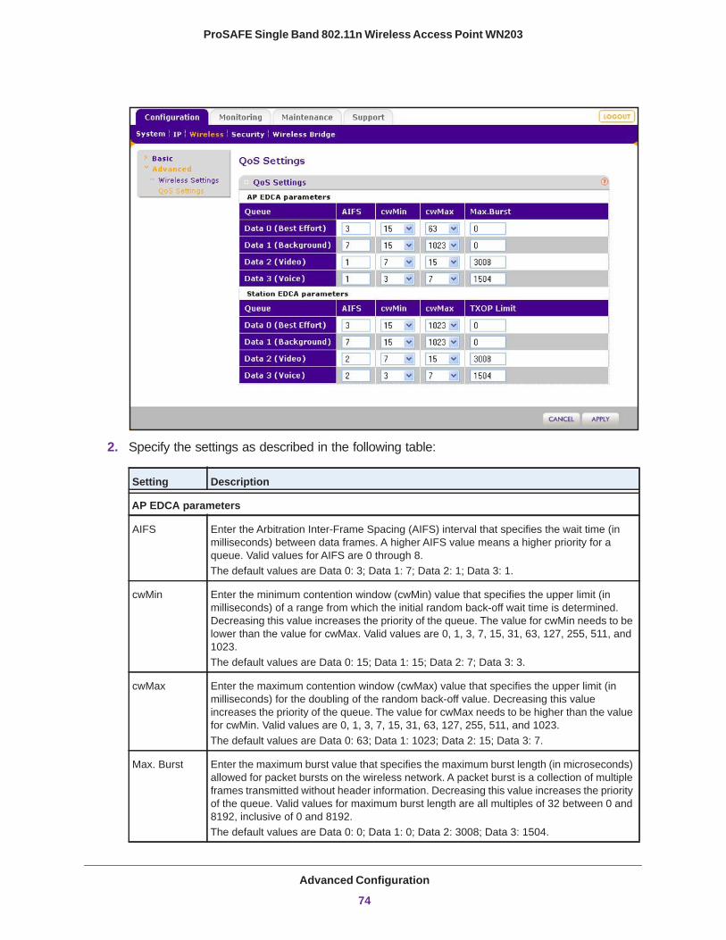
ProSAFE Single Band 802.11n Wireless Access Point WN203
2. Specify the settings as described in the following table:
Setting Description
AP EDCA parameters
AIFS Enter the Arbitration Inter-Frame Spacing (AIFS) interval that specifies the wait time (in milliseconds) between data frames. A higher AIFS value means a higher priority for a queue. Valid values for AIFS are 0 through 8. The default values are Data 0: 3; Data 1: 7; Data 2: 1; Data 3: 1.
cwMin Enter the minimum contention window (cwMin) value that specifies the upper limit (in milliseconds) of a range from which the initial random back-off wait time is determined. Decreasing this value increases the priority of the queue. The value for cwMin needs to be lower than the value for cwMax. Valid values are 0, 1, 3, 7, 15, 31, 63, 127, 255, 511, and 1023.The default values are Data 0: 15; Data 1: 15; Data 2: 7; Data 3: 3.
cwMax Enter the maximum contention window (cwMax) value that specifies the upper limit (in milliseconds) for the doubling of the random back-off value. Decreasing this value increases the priority of the queue. The value for cwMax needs to be higher than the value for cwMin. Valid values are 0, 1, 3, 7, 15, 31, 63, 127, 255, 511, and 1023. The default values are Data 0: 63; Data 1: 1023; Data 2: 15; Data 3: 7.
Max. Burst Enter the maximum burst value that specifies the maximum burst length (in microseconds) allowed for packet bursts on the wireless network. A packet burst is a collection of multiple frames transmitted without header information. Decreasing this value increases the priority of the queue. Valid values for maximum burst length are all multiples of 32 between 0 and 8192, inclusive of 0 and 8192.The default values are Data 0: 0; Data 1: 0; Data 2: 3008; Data 3: 1504.
Advanced Configuration
74
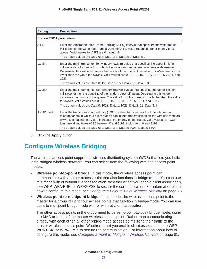
ProSAFE Single Band 802.11n Wireless Access Point WN203
3. Click the Apply button.
Configure Wireless Bridging
The wireless access point supports a wireless distributing system (WDS) that lets you build large bridged wireless networks. You can select from the following wireless access point modes:
• Wireless point-to-point bridge. In this mode, the wireless access point can communicate with another access point that also functions in bridge mode. You can use this mode with or without client association. Whether or not you enable client association, use WEP, WPA-PSK, or WPA2-PSK to secure the communication. For information about how to configure this mode, see Configure a Point-to-Point Wireless Network on page 76.
• Wireless point-to-multipoint bridge. In this mode, the wireless access point is the master for a group of up to four access points that function in bridge-mode. You can use point-to-multipoint bridge mode with or without client association.
The other access points in the group need to be set to point-to-point bridge mode, using the MAC address of the master wireless access point. Rather than communicating directly with each other, all other bridge-mode access points send their traffic to the master wireless access point. Whether or not you enable client association, use WEP, WPA-PSK, or WPA2-PSK to secure the communication. For information about how to configure this mode, see Configure a Point-to-Multipoint Wireless Network on page 81.
Station EDCA parameters
AIFS Enter the Arbitration Inter-Frame Spacing (AIFS) interval that specifies the wait time (in milliseconds) between data frames. A higher AIFS value means a higher priority for a queue. Valid values for AIFS are 0 through 8. The default values are Data 0: 3; Data 1: 7; Data 2: 2; Data 3: 2.
cwMin Enter the minimum contention window (cwMin) value that specifies the upper limit (in milliseconds) of a range from which the initial random back-off wait time is determined. Decreasing this value increases the priority of the queue. The value for cwMin needs to be lower than the value for cwMax. Valid values are 0, 1, 3, 7, 15, 31, 63, 127, 255, 511, and 1023.The default values are Data 0: 15; Data 1: 15; Data 2: 7; Data 3: 3.
cwMax Enter the maximum contention window (cwMax) value that specifies the upper limit (in milliseconds) for the doubling of the random back-off value. Decreasing this value increases the priority of the queue. The value for cwMax needs to be higher than the value for cwMin. Valid values are 0, 1, 3, 7, 15, 31, 63, 127, 255, 511, and 1023. The default values are Data 0: 1023; Data 1: 1023; Data 2: 15; Data 3: 7.
TXOP Limit Enter the transmission opportunity (TXOP) value that specifies the time interval (in microseconds) in which a client station can initiate transmissions on the wireless medium (WM). Decreasing this value increases the priority of the queue. Valid values for TXOP Limit are all multiples of 32 between 0 and 8192, inclusive of 0 and 8192.The default values are Data 0: 0; Data 1: 0; Data 2: 3008; Data 3: 1504.
Setting Description
Advanced Configuration
75
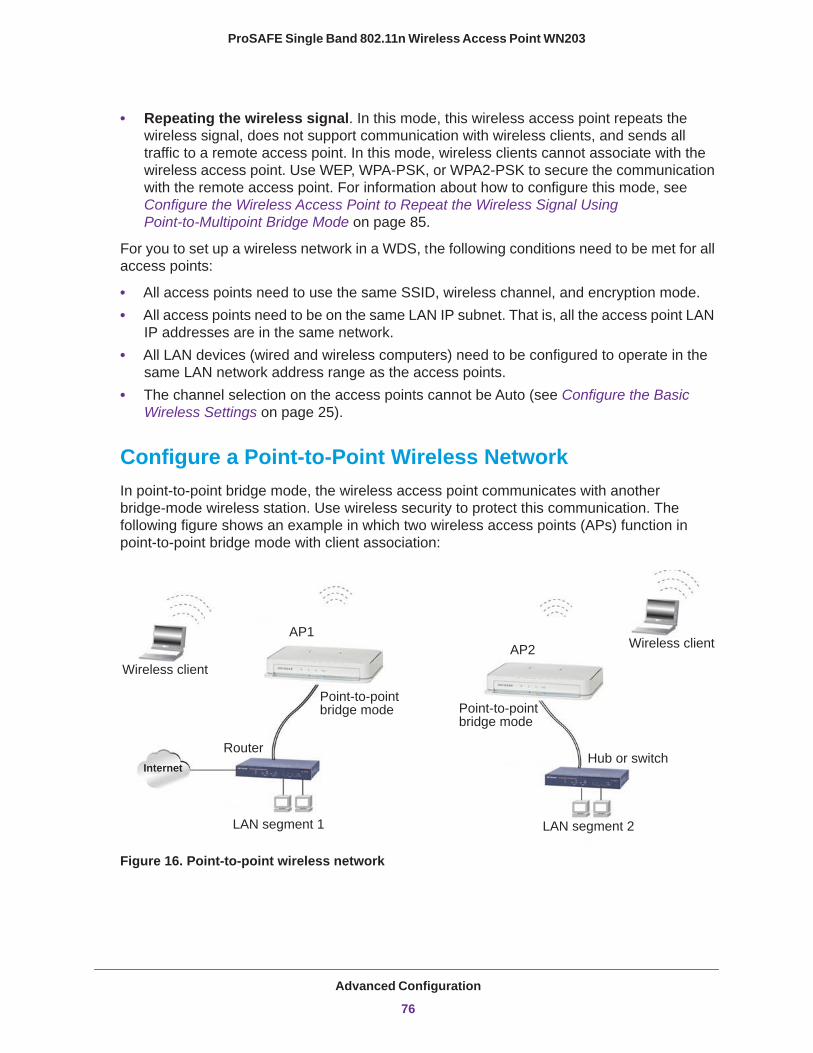
ProSAFE Single Band 802.11n Wireless Access Point WN203
• Repeating the wireless signal. In this mode, this wireless access point repeats the wireless signal, does not support communication with wireless clients, and sends all traffic to a remote access point. In this mode, wireless clients cannot associate with the wireless access point. Use WEP, WPA-PSK, or WPA2-PSK to secure the communication with the remote access point. For information about how to configure this mode, see Configure the Wireless Access Point to Repeat the Wireless Signal Using Point-to-Multipoint Bridge Mode on page 85.
For you to set up a wireless network in a WDS, the following conditions need to be met for all access points:
• All access points need to use the same SSID, wireless channel, and encryption mode.• All access points need to be on the same LAN IP subnet. That is, all the access point LAN
IP addresses are in the same network.• All LAN devices (wired and wireless computers) need to be configured to operate in the
same LAN network address range as the access points.• The channel selection on the access points cannot be Auto (see Configure the Basic
Wireless Settings on page 25).
Configure a Point-to-Point Wireless NetworkIn point-to-point bridge mode, the wireless access point communicates with another bridge-mode wireless station. Use wireless security to protect this communication. The following figure shows an example in which two wireless access points (APs) function in point-to-point bridge mode with client association:
Point-to-pointbridge mode Point-to-point
bridge mode
RouterHub or switch
AP1AP2
Internet
LAN segment 1 LAN segment 2
Wireless client
Wireless client
Figure 16. Point-to-point wireless network
Advanced Configuration
76
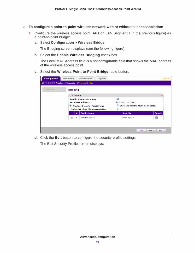
ProSAFE Single Band 802.11n Wireless Access Point WN203
To configure a point-to-point wireless network with or without client association:
1. Configure the wireless access point (AP1 on LAN Segment 1 in the previous figure) as a point-to-point bridge:a. Select Configuration > Wireless Bridge.
The Bridging screen displays (see the following figure).
b. Select the Enable Wireless Bridging check box.
The Local MAC Address field is a nonconfigurable field that shows the MAC address of the wireless access point.
c. Select the Wireless Point-to-Point Bridge radio button.
d. Click the Edit button to configure the security profile settings.
The Edit Security Profile screen displays:
Advanced Configuration
77
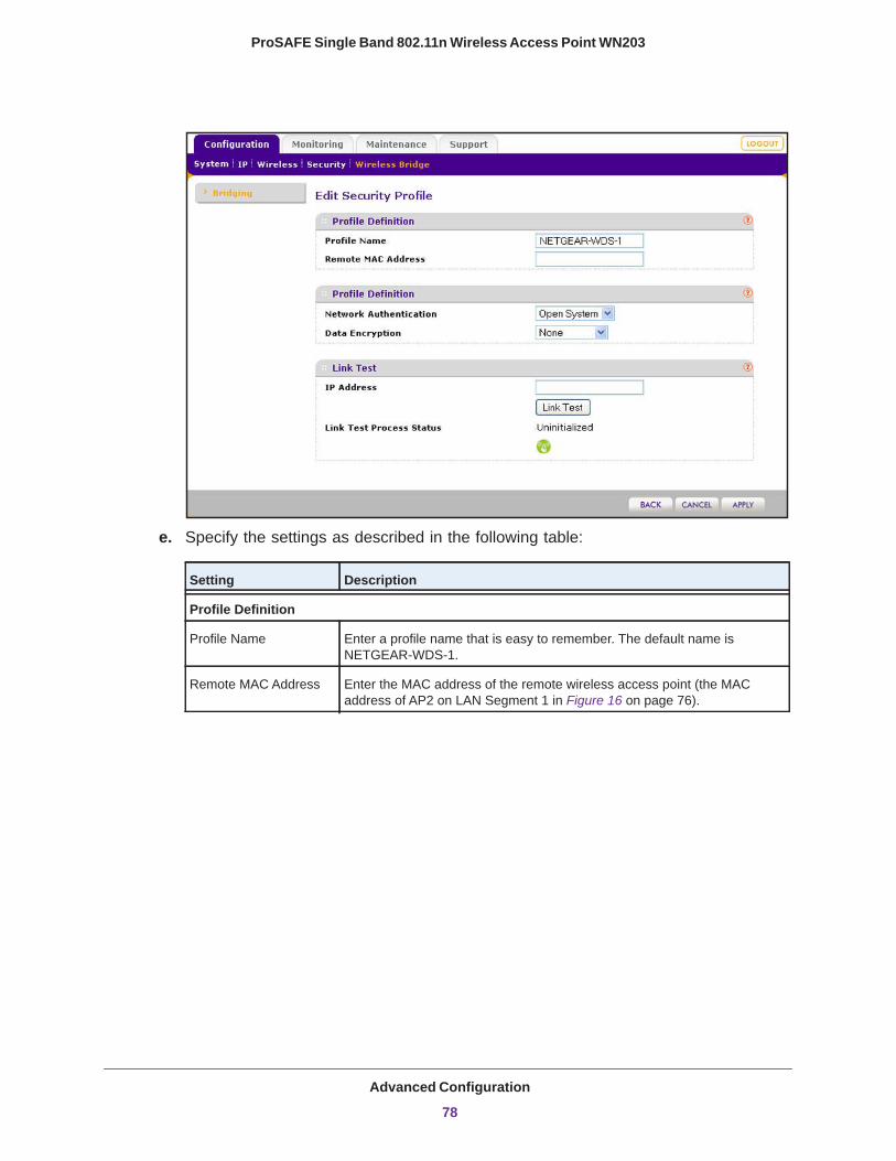
ProSAFE Single Band 802.11n Wireless Access Point WN203
e. Specify the settings as described in the following table:
Setting Description
Profile Definition
Profile Name Enter a profile name that is easy to remember. The default name is NETGEAR-WDS-1.
Remote MAC Address Enter the MAC address of the remote wireless access point (the MAC address of AP2 on LAN Segment 1 in Figure 16 on page 76).
Advanced Configuration
78
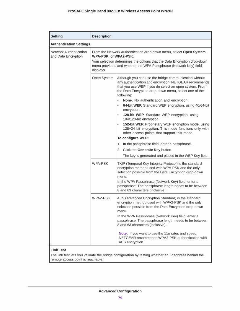
ProSAFE Single Band 802.11n Wireless Access Point WN203
Authentication Settings
Network Authentication and Data Encryption
From the Network Authentication drop-down menu, select Open System, WPA-PSK, or WPA2-PSK. Your selection determines the options that the Data Encryption drop-down menu provides, and whether the WPA Passphrase (Network Key) field displays.
Open System Although you can use the bridge communication without any authentication and encryption, NETGEAR recommends that you use WEP if you do select an open system. From the Data Encryption drop-down menu, select one of the following:• None. No authentication and encryption.• 64-bit WEP. Standard WEP encryption, using 40/64-bit
encryption.• 128-bit WEP. Standard WEP encryption, using
104/128-bit encryption.• 152-bit WEP. Proprietary WEP encryption mode, using
128+24 bit encryption. This mode functions only with other access points that support this mode.
To configure WEP:1. In the passphrase field, enter a passphrase.
2. Click the Generate Key button.
The key is generated and placed in the WEP Key field.
WPA-PSK TKIP (Temporal Key Integrity Protocol) is the standard encryption method used with WPA-PSK and the only selection possible from the Data Encryption drop-down menu.In the WPA Passphrase (Network Key) field, enter a passphrase. The passphrase length needs to be between 8 and 63 characters (inclusive).
WPA2-PSK AES (Advanced Encryption Standard) is the standard encryption method used with WPA2-PSK and the only selection possible from the Data Encryption drop-down menu.In the WPA Passphrase (Network Key) field, enter a passphrase. The passphrase length needs to be between 8 and 63 characters (inclusive).
Note: If you want to use the 11n rates and speed, NETGEAR recommends WPA2-PSK authentication with AES encryption.
Link TestThe link test lets you validate the bridge configuration by testing whether an IP address behind the remote access point is reachable.
Setting Description
Advanced Configuration
79

ProSAFE Single Band 802.11n Wireless Access Point WN203
f. Click the Apply button.
The bridge configuration is saved. The Bridging screen displays again.
g. (Optional) Clear the Enable Wireless Client Association check box to disable wireless client association while the wireless access point functions as a point-to-point bridge.
By default, the Enable Wireless Client Association check box is selected and wireless client association is enabled.
h. If the correct profile name and security option are displayed in the table, select the check box in the Enable column.
i. Click the Apply button.
The point-to-point bridge settings are saved.
2. Configure a second wireless access point (AP2) on LAN Segment 2 (see Figure 16 on page 76) in point-to-point bridge mode.
AP1 needs to have AP2’s MAC address in its Remote MAC Address field, and AP2 needs to have AP1’s MAC address in its Remote MAC Address field.
3. Verify the following settings for both wireless access points:• Both APs are configured to operate in the same LAN network address range as the
LAN devices.• If you use DHCP, both APs can obtain an IP address automatically (as a DHCP
client). For more information, see Configure the IP Settings on page 22.• Both APs use the same channel, authentication mode, and security settings.
4. Verify connectivity across the LANs.
A computer on any LAN segment should be able to connect to the Internet or share files and printers with any other computers or servers connected to any of the two LAN segments.
IP Address Enter an IP address that can be reached through the remote access point for which you are setting up a bridge configuration. Click the Link Test button.
Link Test Process Status After one minute or less, the link test returns one of the following results:• Success. The link can be established using the bridge configuration,
and the IP address behind the remote access point is reachable. You can click the Apply button to save the bridge configuration.
• Failure. The link cannot be established using the bridge configuration. Either the remote access point is not configured correctly or the IP address behind the remote access point is not reachable.
Setting Description
Advanced Configuration
80
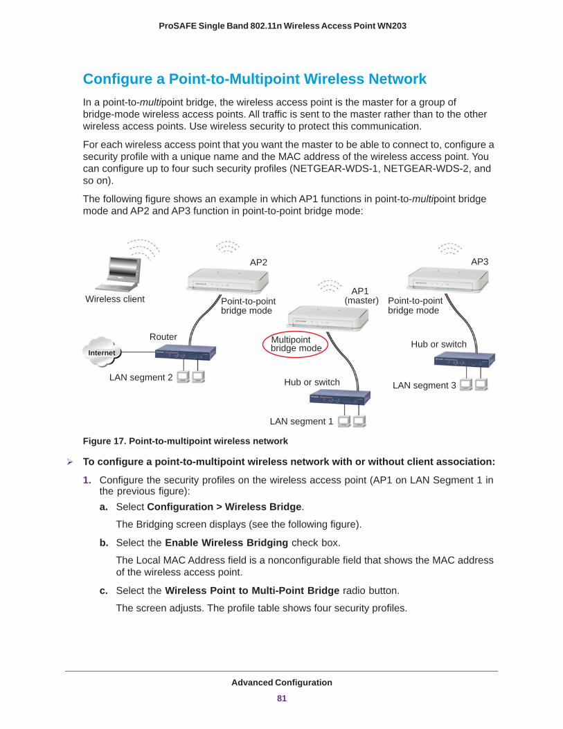
ProSAFE Single Band 802.11n Wireless Access Point WN203
Configure a Point-to-Multipoint Wireless NetworkIn a point-to-multipoint bridge, the wireless access point is the master for a group of bridge-mode wireless access points. All traffic is sent to the master rather than to the other wireless access points. Use wireless security to protect this communication.
For each wireless access point that you want the master to be able to connect to, configure a security profile with a unique name and the MAC address of the wireless access point. You can configure up to four such security profiles (NETGEAR-WDS-1, NETGEAR-WDS-2, and so on).
The following figure shows an example in which AP1 functions in point-to-multipoint bridge mode and AP2 and AP3 function in point-to-point bridge mode:
Point-to-pointbridge mode
Multipointbridge mode
Point-to-pointbridge mode
RouterHub or switch
Hub or switch
Internet
Wireless client
LAN segment 1
LAN segment 2LAN segment 3
AP1(master)
AP2 AP3
Figure 17. Point-to-multipoint wireless network
To configure a point-to-multipoint wireless network with or without client association:
1. Configure the security profiles on the wireless access point (AP1 on LAN Segment 1 in the previous figure):a. Select Configuration > Wireless Bridge.
The Bridging screen displays (see the following figure).
b. Select the Enable Wireless Bridging check box.
The Local MAC Address field is a nonconfigurable field that shows the MAC address of the wireless access point.
c. Select the Wireless Point to Multi-Point Bridge radio button.
The screen adjusts. The profile table shows four security profiles.
Advanced Configuration
81
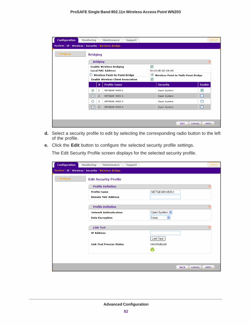
ProSAFE Single Band 802.11n Wireless Access Point WN203
d. Select a security profile to edit by selecting the corresponding radio button to the left of the profile.
e. Click the Edit button to configure the selected security profile settings.
The Edit Security Profile screen displays for the selected security profile.
Advanced Configuration
82
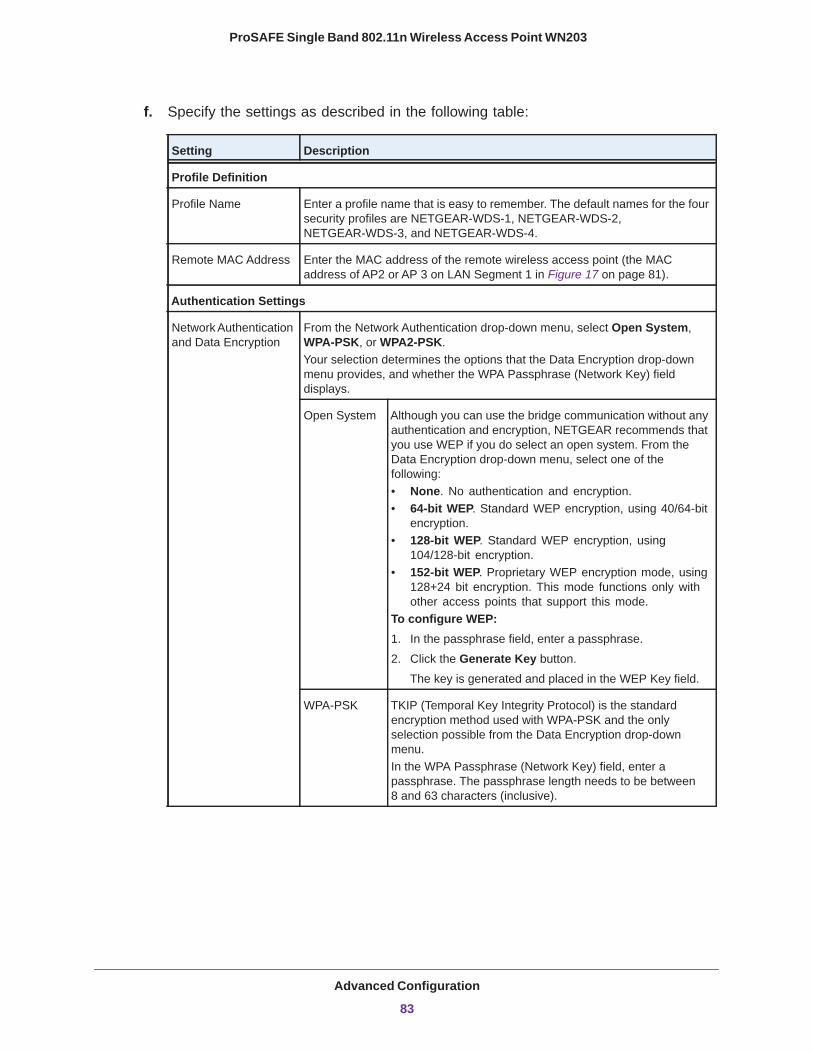
ProSAFE Single Band 802.11n Wireless Access Point WN203
f. Specify the settings as described in the following table:
Setting Description
Profile Definition
Profile Name Enter a profile name that is easy to remember. The default names for the four security profiles are NETGEAR-WDS-1, NETGEAR-WDS-2, NETGEAR-WDS-3, and NETGEAR-WDS-4.
Remote MAC Address Enter the MAC address of the remote wireless access point (the MAC address of AP2 or AP 3 on LAN Segment 1 in Figure 17 on page 81).
Authentication Settings
Network Authentication and Data Encryption
From the Network Authentication drop-down menu, select Open System, WPA-PSK, or WPA2-PSK. Your selection determines the options that the Data Encryption drop-down menu provides, and whether the WPA Passphrase (Network Key) field displays.
Open System Although you can use the bridge communication without any authentication and encryption, NETGEAR recommends that you use WEP if you do select an open system. From the Data Encryption drop-down menu, select one of the following:• None. No authentication and encryption.• 64-bit WEP. Standard WEP encryption, using 40/64-bit
encryption.• 128-bit WEP. Standard WEP encryption, using
104/128-bit encryption.• 152-bit WEP. Proprietary WEP encryption mode, using
128+24 bit encryption. This mode functions only with other access points that support this mode.
To configure WEP:1. In the passphrase field, enter a passphrase.
2. Click the Generate Key button.
The key is generated and placed in the WEP Key field.
WPA-PSK TKIP (Temporal Key Integrity Protocol) is the standard encryption method used with WPA-PSK and the only selection possible from the Data Encryption drop-down menu.In the WPA Passphrase (Network Key) field, enter a passphrase. The passphrase length needs to be between 8 and 63 characters (inclusive).
Advanced Configuration
83
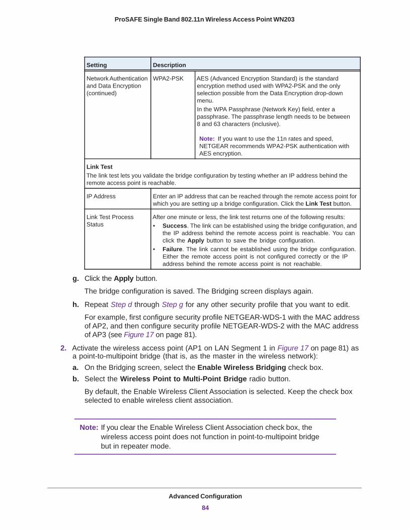
ProSAFE Single Band 802.11n Wireless Access Point WN203
g. Click the Apply button.
The bridge configuration is saved. The Bridging screen displays again.
h. Repeat Step d through Step g for any other security profile that you want to edit.
For example, first configure security profile NETGEAR-WDS-1 with the MAC address of AP2, and then configure security profile NETGEAR-WDS-2 with the MAC address of AP3 (see Figure 17 on page 81).
2. Activate the wireless access point (AP1 on LAN Segment 1 in Figure 17 on page 81) as a point-to-multipoint bridge (that is, as the master in the wireless network):a. On the Bridging screen, select the Enable Wireless Bridging check box.b. Select the Wireless Point to Multi-Point Bridge radio button.
By default, the Enable Wireless Client Association is selected. Keep the check box selected to enable wireless client association.
Note: If you clear the Enable Wireless Client Association check box, the wireless access point does not function in point-to-multipoint bridge but in repeater mode.
Network Authentication and Data Encryption (continued)
WPA2-PSK AES (Advanced Encryption Standard) is the standard encryption method used with WPA2-PSK and the only selection possible from the Data Encryption drop-down menu.In the WPA Passphrase (Network Key) field, enter a passphrase. The passphrase length needs to be between 8 and 63 characters (inclusive).
Note: If you want to use the 11n rates and speed, NETGEAR recommends WPA2-PSK authentication with AES encryption.
Link TestThe link test lets you validate the bridge configuration by testing whether an IP address behind the remote access point is reachable.
IP Address Enter an IP address that can be reached through the remote access point for which you are setting up a bridge configuration. Click the Link Test button.
Link Test Process Status
After one minute or less, the link test returns one of the following results:• Success. The link can be established using the bridge configuration, and
the IP address behind the remote access point is reachable. You can click the Apply button to save the bridge configuration.
• Failure. The link cannot be established using the bridge configuration. Either the remote access point is not configured correctly or the IP address behind the remote access point is not reachable.
Setting Description
Advanced Configuration
84
ProSAFE Single Band 802.11n Wireless Access Point WN203
c. If the correct profile names and security options are displayed in the table, select the check boxes in the Enable column for all security profiles that you want to enable.
d. On the Bridging screen, click the Apply button.
The point-to-multipoint bridge settings are activated.
3. Configure AP2 on LAN Segment 2 (see Figure 17 on page 81) in point-to-point bridge mode with the remote MAC address of AP1.
4. Configure AP3 on LAN Segment 3 (see Figure 17 on page 81) in point-to-point bridge mode with the remote MAC address of AP1.
5. Verify the following:• Only AP1 on LAN Segment 1 is configured in point-to-multipoint bridge mode, and all
others wireless access points are configured in point-to-point bridge mode.• AP2 and AP3 (the point-to-point APs) have AP1’s MAC address in their Remote MAC
Address field.• All APs are configured to operate in the same LAN network address range as the LAN
devices.• If you use DHCP, all APs can obtain an IP address automatically (as DHCP clients).
For more information, see Configure the IP Settings on page 22.• All APs use the same channel, authentication mode, and security settings.
6. Verify connectivity across the LANs.
A computer on any LAN segment should be able to connect to the Internet or share files and printers with any other computers or servers connected to any of the three LAN segments.
Note: You can extend this multipoint bridging configuration by adding more wireless access points that are configured in point-to-point mode for each additional LAN segment.
Configure the Wireless Access Point to Repeat the Wireless Signal Using Point-to-Multipoint Bridge ModeYou can configure the wireless access point to repeat the wireless signal, without communication with other wireless clients. All traffic is sent to the remote or downstream wireless access point. You can configure up to four security profiles to enable the wireless access point to repeat the wireless signal for four remote wireless access points. Each security profile requires a unique name and needs to include the MAC address of the remote wireless access point. You can configure up to four such security profiles (NETGEAR-WDS-1, NETGEAR-WDS-2, and so on).
The following figure shows an example in which AP1, AP2, and AP3 repeat the wireless signal in point-to-multipoint bridge mode. AP2 requires a security profile for AP1 and another one for AP3:
Advanced Configuration
85

ProSAFE Single Band 802.11n Wireless Access Point WN203
Multipoint
Router
Hub or switch
bridge moderepeating only
Multipointbridge moderepeating only
Multipointbridge moderepeating onlyInternet
AP1
AP2
AP3
LAN segment 1
LAN segment 2Figure 18. Repeating the wireless signal in point-to-multipoint bridge mode
To configure the wireless access point to repeat the wireless signal:
1. Configure the security profiles on the wireless access point (AP2 on LAN Segment 2 in the previous figure):a. Select Configuration > Wireless Bridge.
The Bridging screen displays (see the following figure).
b. Select the Enable Wireless Bridging check box.
The Local MAC Address field is a nonconfigurable field that shows the MAC address of the wireless access point.
c. Select the Wireless Point to Multi-Point Bridge radio button.
The screen adjusts. The profile table shows four security profiles.
Advanced Configuration
86

ProSAFE Single Band 802.11n Wireless Access Point WN203
d. Select a security profile to edit by selecting the corresponding radio button to the left of the profile.
e. Click the Edit button to configure the selected security profile settings.
The Edit Security Profile screen displays for the selected security profile.
Advanced Configuration
87
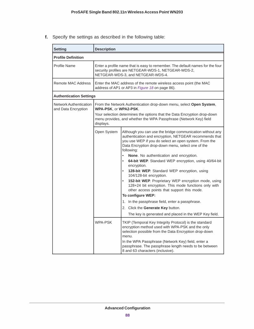
ProSAFE Single Band 802.11n Wireless Access Point WN203
f. Specify the settings as described in the following table:
Setting Description
Profile Definition
Profile Name Enter a profile name that is easy to remember. The default names for the four security profiles are NETGEAR-WDS-1, NETGEAR-WDS-2, NETGEAR-WDS-3, and NETGEAR-WDS-4.
Remote MAC Address Enter the MAC address of the remote wireless access point (the MAC address of AP1 or AP3 in Figure 18 on page 86).
Authentication Settings
Network Authentication and Data Encryption
From the Network Authentication drop-down menu, select Open System, WPA-PSK, or WPA2-PSK. Your selection determines the options that the Data Encryption drop-down menu provides, and whether the WPA Passphrase (Network Key) field displays.
Open System Although you can use the bridge communication without any authentication and encryption, NETGEAR recommends that you use WEP if you do select an open system. From the Data Encryption drop-down menu, select one of the following:• None. No authentication and encryption.• 64-bit WEP. Standard WEP encryption, using 40/64-bit
encryption.• 128-bit WEP. Standard WEP encryption, using
104/128-bit encryption.• 152-bit WEP. Proprietary WEP encryption mode, using
128+24 bit encryption. This mode functions only with other access points that support this mode.
To configure WEP:1. In the passphrase field, enter a passphrase.
2. Click the Generate Key button.
The key is generated and placed in the WEP Key field.
WPA-PSK TKIP (Temporal Key Integrity Protocol) is the standard encryption method used with WPA-PSK and the only selection possible from the Data Encryption drop-down menu.In the WPA Passphrase (Network Key) field, enter a passphrase. The passphrase length needs to be between 8 and 63 characters (inclusive).
Advanced Configuration
88
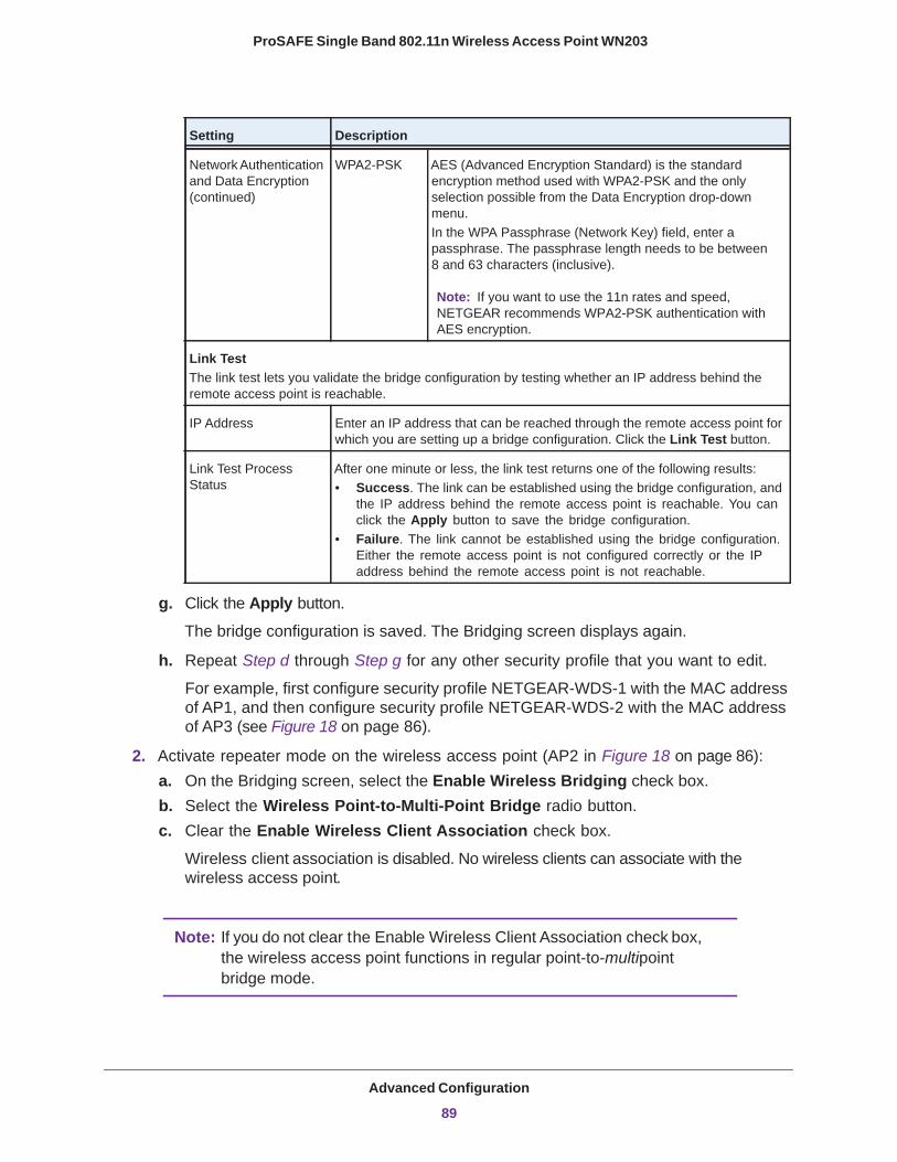
ProSAFE Single Band 802.11n Wireless Access Point WN203
g. Click the Apply button.
The bridge configuration is saved. The Bridging screen displays again.
h. Repeat Step d through Step g for any other security profile that you want to edit.
For example, first configure security profile NETGEAR-WDS-1 with the MAC address of AP1, and then configure security profile NETGEAR-WDS-2 with the MAC address of AP3 (see Figure 18 on page 86).
2. Activate repeater mode on the wireless access point (AP2 in Figure 18 on page 86):a. On the Bridging screen, select the Enable Wireless Bridging check box.b. Select the Wireless Point-to-Multi-Point Bridge radio button.c. Clear the Enable Wireless Client Association check box.
Wireless client association is disabled. No wireless clients can associate with the wireless access point.
Note: If you do not clear the Enable Wireless Client Association check box, the wireless access point functions in regular point-to-multipoint bridge mode.
Network Authentication and Data Encryption (continued)
WPA2-PSK AES (Advanced Encryption Standard) is the standard encryption method used with WPA2-PSK and the only selection possible from the Data Encryption drop-down menu.In the WPA Passphrase (Network Key) field, enter a passphrase. The passphrase length needs to be between 8 and 63 characters (inclusive).
Note: If you want to use the 11n rates and speed, NETGEAR recommends WPA2-PSK authentication with AES encryption.
Link TestThe link test lets you validate the bridge configuration by testing whether an IP address behind the remote access point is reachable.
IP Address Enter an IP address that can be reached through the remote access point for which you are setting up a bridge configuration. Click the Link Test button.
Link Test Process Status
After one minute or less, the link test returns one of the following results:• Success. The link can be established using the bridge configuration, and
the IP address behind the remote access point is reachable. You can click the Apply button to save the bridge configuration.
• Failure. The link cannot be established using the bridge configuration. Either the remote access point is not configured correctly or the IP address behind the remote access point is not reachable.
Setting Description
Advanced Configuration
89
ProSAFE Single Band 802.11n Wireless Access Point WN203
d. If the correct profile names and security options are displayed in the table, select the check boxes in the Enable column for all security profiles that you want to enable.
e. On the Bridging screen, click the Apply button.
The repeater settings are activated.
3. Configure AP1 on LAN Segment 1 (see Figure 18 on page 86) in repeater mode with the remote MAC address of AP2.
4. Configure AP3 on LAN Segment 3 (see Figure 18 on page 86) in repeater mode with the remote MAC address of AP2.
5. Verify the following:• AP1 has AP2’s MAC address in its Remote MAC Address field.• AP3 has AP2’s MAC address in its Remote MAC Address field.• All APs are configured to operate in the same LAN network address range as the LAN
devices.• If you use DHCP, all APs can obtain an IP address automatically (as DHCP clients).
For more information, see Configure the IP Settings on page 22.• All APs use the same channel, authentication mode, and security settings.
6. Verify connectivity across the LANs.
A computer on any LAN segment should be able to connect to the Internet or share files and printers with any other computers or servers connected to any of the two LAN segments.
Note: Between each LAN segment, you can extend repetition of the wireless signal by adding up to two more wireless access points that are configured in point-to-multipoint bridge mode without client association.
Advanced Configuration
90
6
6. MonitoringThis chapter describes how to monitor the wireless access point and its network traffic. The chapter includes the following sections:
• View System Information • Monitor Wireless Clients • View the Activity Log • Traffic Statistics
Note: For information about monitoring rogue and known access points, see View and Save Access Point Lists on page 64.
91
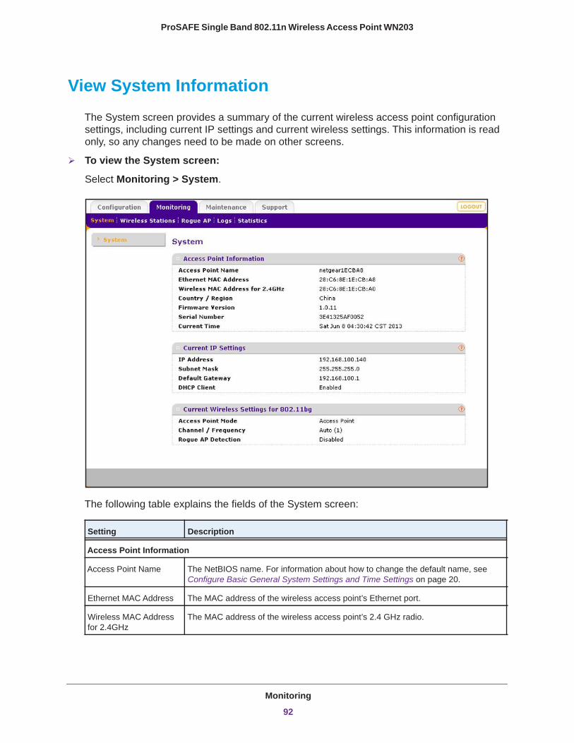
ProSAFE Single Band 802.11n Wireless Access Point WN203
View System Information
The System screen provides a summary of the current wireless access point configuration settings, including current IP settings and current wireless settings. This information is read only, so any changes need to be made on other screens.
To view the System screen:
Select Monitoring > System.
The following table explains the fields of the System screen:
Setting Description
Access Point Information
Access Point Name The NetBIOS name. For information about how to change the default name, see Configure Basic General System Settings and Time Settings on page 20.
Ethernet MAC Address The MAC address of the wireless access point’s Ethernet port.
Wireless MAC Address for 2.4GHz
The MAC address of the wireless access point’s 2.4 GHz radio.
Monitoring
92
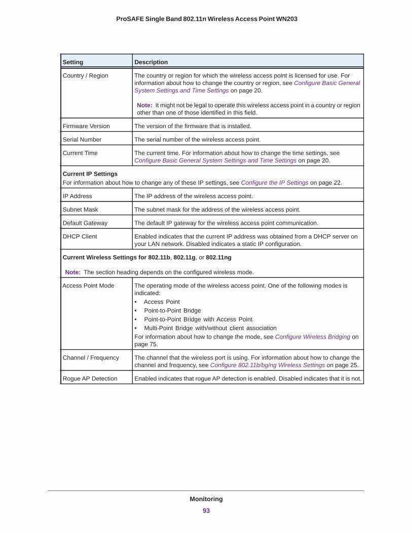
ProSAFE Single Band 802.11n Wireless Access Point WN203
Country / Region The country or region for which the wireless access point is licensed for use. For information about how to change the country or region, see Configure Basic General System Settings and Time Settings on page 20.
Note: It might not be legal to operate this wireless access point in a country or region other than one of those identified in this field.
Firmware Version The version of the firmware that is installed.
Serial Number The serial number of the wireless access point.
Current Time The current time. For information about how to change the time settings, see Configure Basic General System Settings and Time Settings on page 20.
Current IP SettingsFor information about how to change any of these IP settings, see Configure the IP Settings on page 22.
IP Address The IP address of the wireless access point.
Subnet Mask The subnet mask for the address of the wireless access point.
Default Gateway The default IP gateway for the wireless access point communication.
DHCP Client Enabled indicates that the current IP address was obtained from a DHCP server on your LAN network. Disabled indicates a static IP configuration.
Current Wireless Settings for 802.11b, 802.11g, or 802.11ng
Note: The section heading depends on the configured wireless mode.
Access Point Mode The operating mode of the wireless access point. One of the following modes is indicated:• Access Point• Point-to-Point Bridge• Point-to-Point Bridge with Access Point• Multi-Point Bridge with/without client associationFor information about how to change the mode, see Configure Wireless Bridging on page 75.
Channel / Frequency The channel that the wireless port is using. For information about how to change the channel and frequency, see Configure 802.11b/bg/ng Wireless Settings on page 25.
Rogue AP Detection Enabled indicates that rogue AP detection is enabled. Disabled indicates that it is not.
Setting Description
Monitoring
93
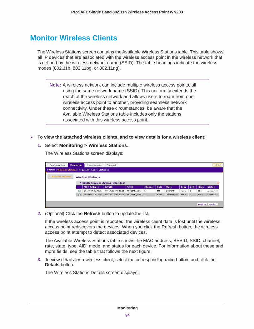
ProSAFE Single Band 802.11n Wireless Access Point WN203
Monitor Wireless Clients
The Wireless Stations screen contains the Available Wireless Stations table. This table shows all IP devices that are associated with the wireless access point in the wireless network that is defined by the wireless network name (SSID). The table headings indicate the wireless modes (802.11b, 802.11bg, or 802.11ng).
Note: A wireless network can include multiple wireless access points, all using the same network name (SSID). This uniformity extends the reach of the wireless network and allows users to roam from one wireless access point to another, providing seamless network connectivity. Under these circumstances, be aware that the Available Wireless Stations table includes only the stations associated with this wireless access point.
To view the attached wireless clients, and to view details for a wireless client:
1. Select Monitoring > Wireless Stations.
The Wireless Stations screen displays:
2. (Optional) Click the Refresh button to update the list.
If the wireless access point is rebooted, the wireless client data is lost until the wireless access point rediscovers the devices. When you click the Refresh button, the wireless access point attempt to detect associated devices.
The Available Wireless Stations table shows the MAC address, BSSID, SSID, channel, rate, state, type, AID, mode, and status for each device. For information about these and more fields, see the table that follows the next figure.
3. To view details for a wireless client, select the corresponding radio button, and click the Details button.
The Wireless Stations Details screen displays:
Monitoring
94

ProSAFE Single Band 802.11n Wireless Access Point WN203
The following table explains the fields of the Wireless Stations Details screen:
Setting Description
MAC Address The MAC address of the wireless client.
BSSID The BSSID that the wireless client is using.
SSID The SSID that the wireless client is using.
Channel The channel that the wireless client is using.
Rate The transmit data rate in Mbps of the wireless client.
State The features that are enabled on the wireless client.
Type The authentication and encryption type that the wireless client is using.
AID The associated identifier (AID) of the wireless client.
Mode The wireless mode in which the wireless client is operating.
Status The wireless status of the wireless client (Associated).
RSSI The received signal strength indicator (RSSI) of the wireless client.
Idle Time The time since the last frame was received from the wireless client.
Tx Sequence The sequence number of the last frame that was transmitted to the wireless client.
Rx Sequence The sequence number of the last frame that was received from the wireless client.
Capability The summary of the capability of the wireless client that was detected during association.
Monitoring
95
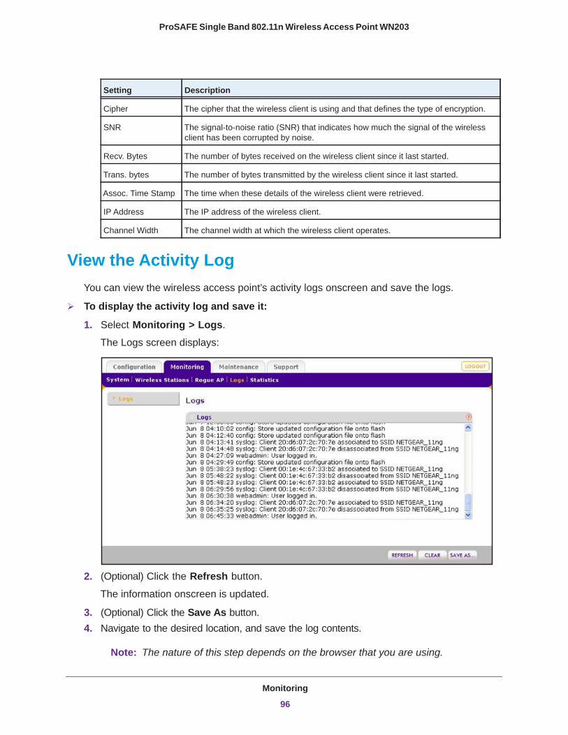
ProSAFE Single Band 802.11n Wireless Access Point WN203
View the Activity LogYou can view the wireless access point’s activity logs onscreen and save the logs.
To display the activity log and save it:
1. Select Monitoring > Logs. The Logs screen displays:
2. (Optional) Click the Refresh button.
The information onscreen is updated.
3. (Optional) Click the Save As button.4. Navigate to the desired location, and save the log contents.
Note: The nature of this step depends on the browser that you are using.
Cipher The cipher that the wireless client is using and that defines the type of encryption.
SNR The signal-to-noise ratio (SNR) that indicates how much the signal of the wireless client has been corrupted by noise.
Recv. Bytes The number of bytes received on the wireless client since it last started.
Trans. bytes The number of bytes transmitted by the wireless client since it last started.
Assoc. Time Stamp The time when these details of the wireless client were retrieved.
IP Address The IP address of the wireless client.
Channel Width The channel width at which the wireless client operates.
Setting Description
Monitoring
96

ProSAFE Single Band 802.11n Wireless Access Point WN203
5. (Optional) Click the Clear button.
The log contents are cleared.
Traffic Statistics
The Statistics screen displays information for both wired (LAN) and wireless (WLAN) network traffic.
To display the Statistics screen:
Select Monitoring > Statistics.
To update the statistics information, click the Refresh button.
Monitoring
97
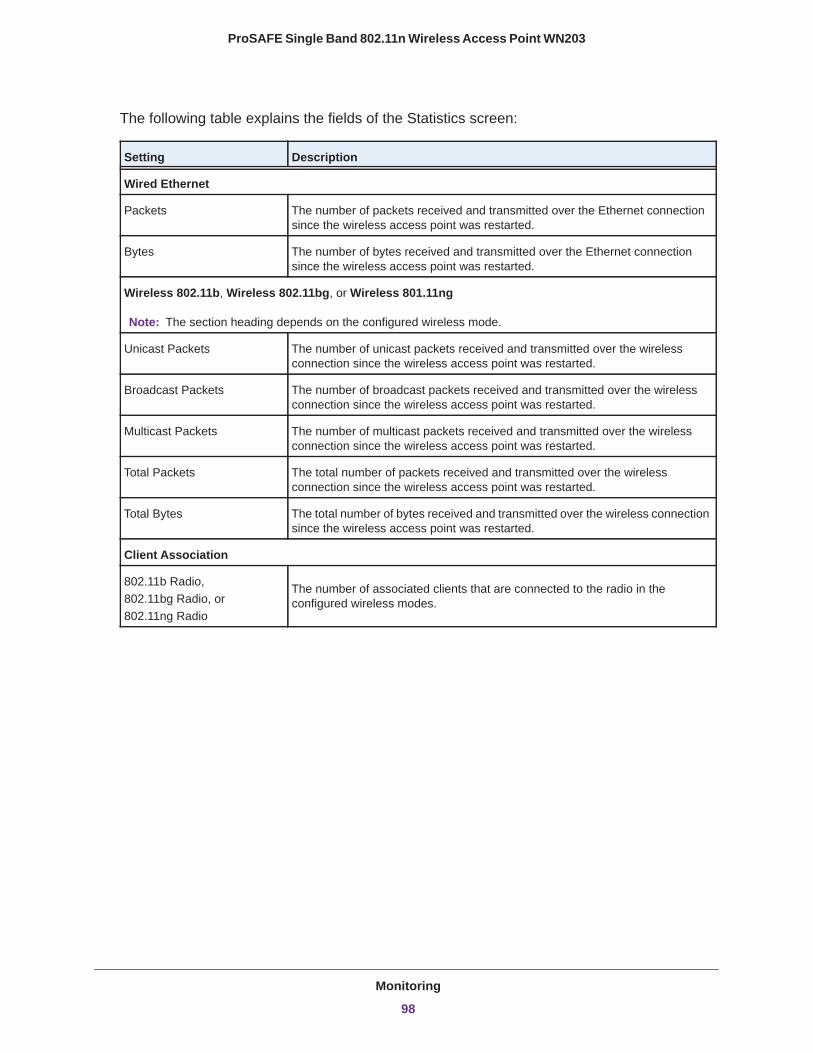
ProSAFE Single Band 802.11n Wireless Access Point WN203
The following table explains the fields of the Statistics screen:
Setting Description
Wired Ethernet
Packets The number of packets received and transmitted over the Ethernet connection since the wireless access point was restarted.
Bytes The number of bytes received and transmitted over the Ethernet connection since the wireless access point was restarted.
Wireless 802.11b, Wireless 802.11bg, or Wireless 801.11ng
Unicast Packets The number of unicast packets received and transmitted over the wireless connection since the wireless access point was restarted.
Broadcast Packets The number of broadcast packets received and transmitted over the wireless connection since the wireless access point was restarted.
Multicast Packets The number of multicast packets received and transmitted over the wireless connection since the wireless access point was restarted.
Total Packets The total number of packets received and transmitted over the wireless connection since the wireless access point was restarted.
Total Bytes The total number of bytes received and transmitted over the wireless connection since the wireless access point was restarted.
Client Association
802.11b Radio,802.11bg Radio, or802.11ng Radio
Note: The section heading depends on the configured wireless mode.
The number of associated clients that are connected to the radio in the configured wireless modes.
Monitoring
98
7
7. TroubleshootingThis chapter provides information about troubleshooting the wireless access point. After each problem description, instructions are given to help you diagnose and solve the problem. For the common problems listed, go to the section indicated.
• Is the wireless access point on?
See Basic Functioning on page 100.
• Did I connect the wireless access point correctly?
See Basic Functioning on page 100.
• I cannot access the Internet or the LAN.
See You Cannot Access the Internet or the LAN from a Wireless-Capable Computer on page 101.
• I cannot access the wireless access point from a browser.
See You Cannot Configure the Wireless Access Point from a Browser on page 102.
• A time-out occurs.
See When You Enter a URL or IP Address a Time-Out Error Occurs on page 103.
• I have problems with the LAN connection.
See Troubleshoot a TCP/IP Network Using the Ping Utility on page 103.
• The date or time is not correct.
See Problems with Date and Time on page 105.
You can find the following troubleshooting information in Chapter 4, Management:
• I cannot remember the wireless access point’s configuration password.
See Change the Administrator Password on page 61.
• I want to clear the configuration and start over again.
See Restore the Wireless Access Point to the Factory Default Settings on page 58.
99
ProSAFE Single Band 802.11n Wireless Access Point WN203
Basic Functioning
This section describes how you can use the LEDs to troubleshoot the wireless access point.
• Verify the Correct Sequence of Events at Startup• No LEDs Are Lit on the Wireless Access Point• LAN LED Is Not Lit• WLAN LED Is Not Lit
Note: For descriptions of the LEDs, see Front Panel on page 11.
Verify the Correct Sequence of Events at Startup After you turn on power to the wireless access point, check that the following
sequence of events occurs:
• The Power LED is green. If the Power LED is off, check the connections, and check if the power outlet is controlled by a wall switch that is turned off.
• The Test LED is amber. After about one minute, the Test LED turns off.• The LAN LED indicates the LAN speed for the LAN port: green for 1000 Mbps or amber
for 100 Mbps or 10 Mbps.• The WLAN LED is blue when the wireless LAN (WLAN) is ready.
If any of these conditions does not occur, see the appropriate following section.
No LEDs Are Lit on the Wireless Access PointIt takes a few seconds for the Power LED to light. Wait 15 seconds and check the Power LED status on the wireless access point.
If the wireless access point has no power and you use a PoE switch to provide power to the wireless access point:
• Make sure that the Ethernet cable between the wireless access point and the PoE switch is connected correctly at both ends.
• Make sure that the power cord of the PoE switch is plugged into a working power outlet or power strip.
• Make sure that the PoE switch is functioning normally.
Troubleshooting
100
ProSAFE Single Band 802.11n Wireless Access Point WN203
If the wireless access point has no power and you use a power cord to provide power to the wireless access point:
• Make sure that the power cord is connected to the wireless access point.• Make sure that the power adapter is connected to a functioning power outlet. If it is in a
power strip, make sure that the power strip is turned on. If it is plugged directly into the wall, verify that it is not a switched outlet.
• Make sure that you are using the correct NETGEAR power adapter that is supplied with your wireless access point.
LAN LED Is Not LitThere is a hardware connection problem.
Check these items:
• Make sure that the cable connectors are securely plugged in at the wireless access point and the network device—hub, (PoE) switches, or router.
• Make sure that the connected device is turned on.• Make sure that the correct cable is used. Use a standard straight-through Category 5
Ethernet cable such as the one that came with the wireless access point. If the network device has Auto Uplink (MDI/MDIX) ports, you can use either a crossover cable or a normal straight-through cable.
WLAN LED Is Not LitThe wireless access point’s antenna is not working. If the WLAN LED remains off, either disconnect the cables to the PoE switches and then reconnect them again, or disconnect the adapter from its power source and then plug it in again.
Contact NETGEAR technical support if the WLAN LED remains off.
You Cannot Access the Internet or the LAN from a Wireless-Capable Computer
There is a configuration problem.
Check these items:
• You might not have restarted the computer with the wireless adapter to allow TCP/IP changes to take effect. Restart the computer.
• The computer with the wireless adapter might not have the correct TCP/IP settings to communicate with the network. Restart the computer and check that TCP/IP is set up correctly for that network. In Windows, the usual setting for Network Properties is to obtain an IP address automatically.
Troubleshooting
101
ProSAFE Single Band 802.11n Wireless Access Point WN203
• The wireless access point’s default values might not work with your network. Check the wireless access point’s default configuration against the configuration of other devices in your network.
• Make sure that the SSID, network authentication, and data encryption settings of the computer with the wireless adapter are the same as those of the wireless access point.
• Ping the IP address of the wireless access point to verify that a wireless connection exists between the computer with the wireless adapter and the wireless access point. If the ping fails, check the network configuration for the wireless access point (see Configure the IP Settings on page 22).
• Ping the default gateway to verify that a path exists from the computer with the wireless adapter to the default gateway. If the ping fails, check the network configuration or call the Internet service provider (ISP).
You Cannot Configure the Wireless Access Point from a Browser
Check these items:
• The wireless access point is correctly installed, it is powered on, and LAN connections are okay. Check that the Active LED and LAN LED are lit to verify that the Ethernet connection is okay.
• If your computer uses a fixed (static) IP address, ensure that it is using an IP address in the range of the wireless access point. The wireless access point’s default IP address is 192.168.0.100, its subnet mask is 255.255.255.0, and the DHCP client is disabled. Make sure that your network configuration settings are correct.
• If you are using the NetBIOS name of the wireless access point to connect, ensure that your computer and the wireless access point are on the same network segment or that your network includes a WINS server.
• If your computer is set to obtain an IP address automatically (DHCP client), restart it.• Make sure that your browser has Java, JavaScript, or ActiveX enabled. If you are using
Internet Explorer, click the Refresh button to be sure that the Java applet is loaded.• Try quitting the browser, clearing the cache, deleting the cookies, and launching the
browser again.• Make sure that you are using the correct login information. The factory default login name
is admin, and the password is password. Make sure that Caps Lock is off when entering this information.
If the wireless access point does not save changes you have made in the web management interface, check the following:
• When entering configuration settings, be sure to click the Apply button before moving to another screen or tab, or your changes are lost.
• Click the Refresh or Reload button in the web browser. The changes might have occurred, but the web browser might be caching the old configuration.
Troubleshooting
102
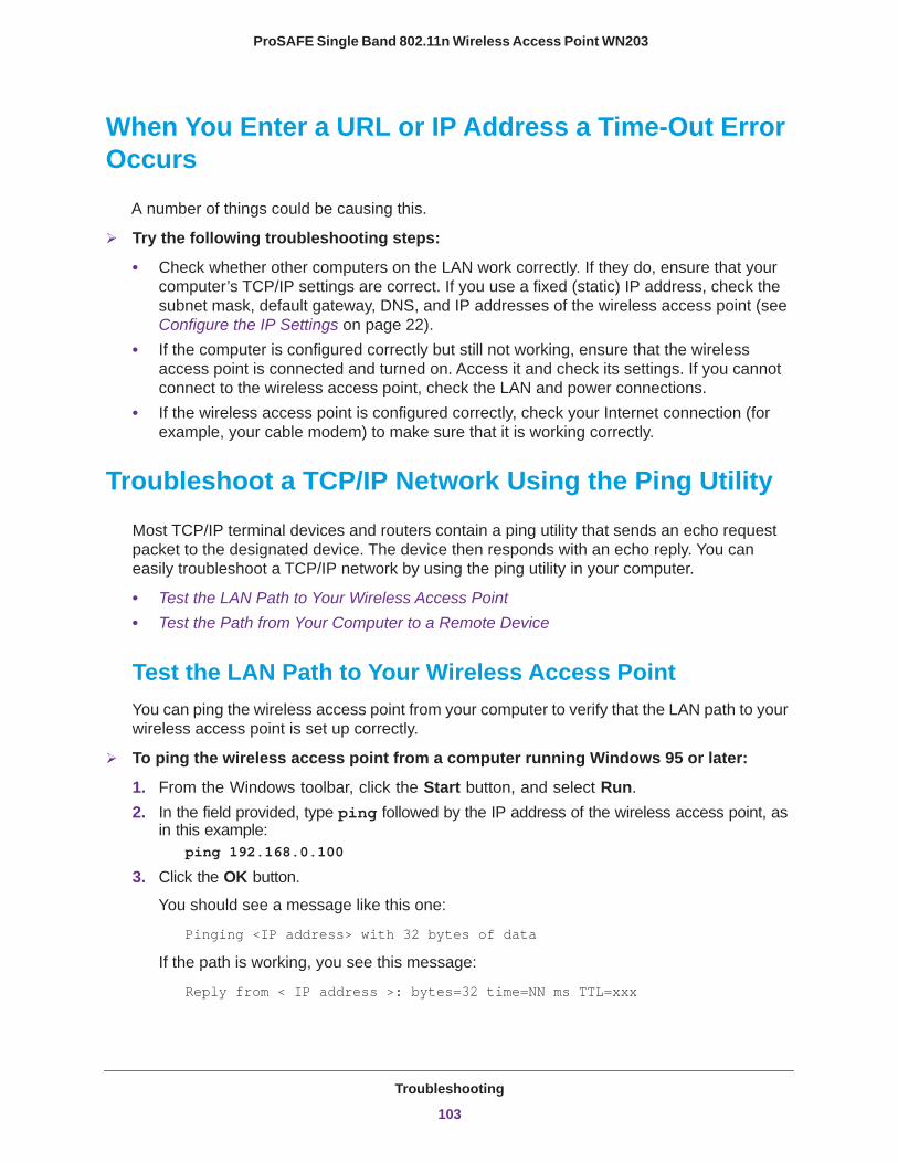
ProSAFE Single Band 802.11n Wireless Access Point WN203
When You Enter a URL or IP Address a Time-Out Error Occurs
A number of things could be causing this.
Try the following troubleshooting steps:
• Check whether other computers on the LAN work correctly. If they do, ensure that your computer’s TCP/IP settings are correct. If you use a fixed (static) IP address, check the subnet mask, default gateway, DNS, and IP addresses of the wireless access point (see Configure the IP Settings on page 22).
• If the computer is configured correctly but still not working, ensure that the wireless access point is connected and turned on. Access it and check its settings. If you cannot connect to the wireless access point, check the LAN and power connections.
• If the wireless access point is configured correctly, check your Internet connection (for example, your cable modem) to make sure that it is working correctly.
Troubleshoot a TCP/IP Network Using the Ping Utility
Most TCP/IP terminal devices and routers contain a ping utility that sends an echo request packet to the designated device. The device then responds with an echo reply. You can easily troubleshoot a TCP/IP network by using the ping utility in your computer.
• Test the LAN Path to Your Wireless Access Point• Test the Path from Your Computer to a Remote Device
Test the LAN Path to Your Wireless Access PointYou can ping the wireless access point from your computer to verify that the LAN path to your wireless access point is set up correctly.
To ping the wireless access point from a computer running Windows 95 or later:
1. From the Windows toolbar, click the Start button, and select Run.2. In the field provided, type ping followed by the IP address of the wireless access point, as
in this example: ping 192.168.0.100
3. Click the OK button.
You should see a message like this one:
Pinging <IP address> with 32 bytes of data
If the path is working, you see this message:
Reply from < IP address >: bytes=32 time=NN ms TTL=xxx
Troubleshooting
103
ProSAFE Single Band 802.11n Wireless Access Point WN203
If the path is not working, you see this message:
Request timed out
If the path is not functioning correctly, you might have one of the following problems:
• Wrong physical connections:- Make sure that the Active LED and LAN LED are lit. If one or both of these LEDs
are off, follow the instructions in LAN LED Is Not Lit on page 101.- Check that the corresponding link LEDs are lit on the hub, switch, or router ports
that are connected to your computer and the wireless access point.• Wrong network configuration:
- Verify that the Ethernet card driver software and TCP/IP software are both installed and configured on your computer.
- Verify that the IP address for your wireless access point and your workstation are correct and that the addresses are on the same subnet.
Test the Path from Your Computer to a Remote DeviceAfter verifying that the LAN path works correctly, test the path from your computer to a remote device.
1. From the Windows toolbar, click the Start button, and select Run.2. In the Windows Run window, type:
ping -n 10 <IP address>
where <IP address> is the IP address of a remote device such as the DNS server of your ISP.
If the path is functioning correctly, replies as in the previous section display. If you do not receive replies:
• Check that your computer has the IP address of your router listed as the default wireless access point. If the IP configuration of your computer is assigned by DHCP, this information is not visible in your computer’s Network Control Panel. Verify that the IP address of the router is listed as the default wireless access point.
• Check to see that the network address of your computer (the portion of the IP address specified by the netmask) is different from the network address of the remote device.
• Check that your cable or DSL modem is connected and functioning.• If your ISP assigned a host name to your computer, enter that host name as the account
name in the basis General system settings screen (see Configure Basic General System Settings and Time Settings on page 20).
Troubleshooting
104
ProSAFE Single Band 802.11n Wireless Access Point WN203
Problems with Date and Time
The Time screen that is accessible through the Configuration > System > Basic > Time menu choices displays the current date and time of day. The wireless access point uses the Network Time Protocol (NTP) to obtain the current time from a network time server on the Internet that you specify in the Time screen (see Configure Basic General System Settings and Time Settings on page 20). Each entry on the Logs screen is stamped with the date and time of day. Problems with the date and time function can include the following:
• Date and time shown is Thu Jan 1 08:00:41 CST 1970 or a similar incorrect date and time. Cause: The wireless access point has not yet successfully reached the network time server. Check that your Internet access settings are configured correctly. If you have just completed configuring the wireless access point, wait at least five minutes and check the date and time again.
• The day is correct or one day ahead or behind, and the hours are ahead or behind. Cause: You have selected an incorrect time zone for your area. Specify the correct time zone on the Time screen (see Configure Basic General System Settings and Time Settings on page 20).
Troubleshooting
105
A
A. Supplemental InformationThis appendix provides factory default settings and technical specifications for the wireless access point. The appendix includes the following sections:
• Technical Specifications • Factory Default Settings
106
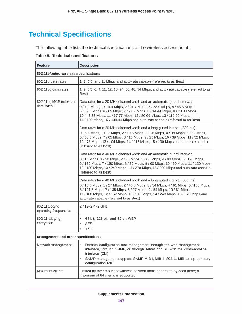
ProSAFE Single Band 802.11n Wireless Access Point WN203
Technical Specifications
The following table lists the technical specifications of the wireless access point:
Table 5. Technical specifications
Feature Description
802.11b/bg/ng wireless specifications
802.11b data rates 1, 2, 5.5, and 11 Mbps, and auto-rate capable (referred to as Best)
802.11bg data rates 1, 2, 5.5, 6, 9, 11, 12, 18, 24, 36, 48, 54 Mbps, and auto-rate capable (referred to as Best)
802.11ng MCS index and data rates
Data rates for a 20 MHz channel width and an automatic guard interval:0 / 7.2 Mbps, 1 / 14.4 Mbps, 2 / 21.7 Mbps, 3 / 28.9 Mbps, 4 / 43.3 Mbps, 5 / 57.8 Mbps, 6 / 65 Mbps, 7 / 72.2 Mbps, 8 / 14.44 Mbps, 9 / 28.88 Mbps, 10 / 43.33 Mbps, 11 / 57.77 Mbps, 12 / 86.66 Mbps, 13 / 115.56 Mbps, 14 / 130 Mbps, 15 / 144.44 Mbps and auto-rate capable (referred to as Best)
Data rates for a 20 MHz channel width and a long guard interval (800 ms):0 / 6.5 Mbps, 1 / 13 Mbps, 2 / 19.5 Mbps, 3 / 26 Mbps, 4 / 39 Mbps, 5 / 52 Mbps, 6 / 58.5 Mbps, 7 / 65 Mbps, 8 / 13 Mbps, 9 / 26 Mbps, 10 / 39 Mbps, 11 / 52 Mbps, 12 / 78 Mbps, 13 / 104 Mbps, 14 / 117 Mbps, 15 / 130 Mbps and auto-rate capable (referred to as Best)
Data rates for a 40 MHz channel width and an automatic guard interval:0 / 15 Mbps, 1 / 30 Mbps, 2 / 45 Mbps, 3 / 60 Mbps, 4 / 90 Mbps, 5 / 120 Mbps, 6 / 135 Mbps, 7 / 150 Mbps, 8 / 30 Mbps, 9 / 60 Mbps, 10 / 90 Mbps, 11 / 120 Mbps, 12 / 180 Mbps, 13 / 240 Mbps, 14 / 270 Mbps, 15 / 300 Mbps and auto-rate capable (referred to as Best)
Data rates for a 40 MHz channel width and a long guard interval (800 ms):0 / 13.5 Mbps, 1 / 27 Mbps, 2 / 40.5 Mbps, 3 / 54 Mbps, 4 / 81 Mbps, 5 / 108 Mbps, 6 / 121.5 Mbps, 7 / 135 Mbps, 8 / 27 Mbps, 9 / 54 Mbps, 10 / 81 Mbps, 11 / 108 Mbps, 12 / 162 Mbps, 13 / 216 Mbps, 14 / 243 Mbps, 15 / 270 Mbps and auto-rate capable (referred to as Best)
802.11b/bg/ng operating frequencies
2.412–2.472 GHz
802.11 b/bg/ng encryption
• 64-bit, 128-bit, and 52-bit WEP• AES• TKIP
Management and other specifications
Network management • Remote configuration and management through the web management interface, through SNMP, or through Telnet or SSH with the command-line interface (CLI).
• SNMP management supports SNMP MIB I, MIB II, 802.11 MIB, and proprietary configuration MIB.
Maximum clients Limited by the amount of wireless network traffic generated by each node; a maximum of 64 clients is supported.
Supplemental Information
107
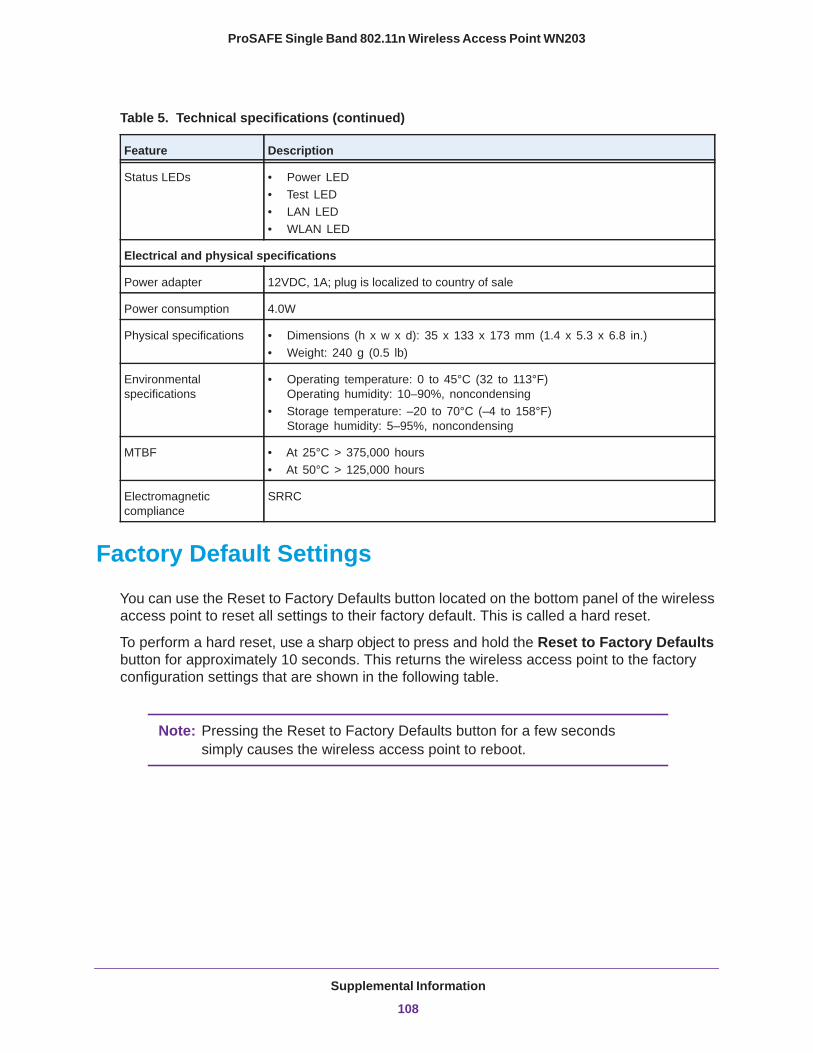
ProSAFE Single Band 802.11n Wireless Access Point WN203
Factory Default Settings
You can use the Reset to Factory Defaults button located on the bottom panel of the wireless access point to reset all settings to their factory default. This is called a hard reset.
To perform a hard reset, use a sharp object to press and hold the Reset to Factory Defaults button for approximately 10 seconds. This returns the wireless access point to the factory configuration settings that are shown in the following table.
Note: Pressing the Reset to Factory Defaults button for a few seconds simply causes the wireless access point to reboot.
Status LEDs • Power LED• Test LED• LAN LED• WLAN LED
Electrical and physical specifications
Power adapter 12VDC, 1A; plug is localized to country of sale
Power consumption 4.0W
Physical specifications • Dimensions (h x w x d): 35 x 133 x 173 mm (1.4 x 5.3 x 6.8 in.)• Weight: 240 g (0.5 lb)
Environmental specifications
• Operating temperature: 0 to 45°C (32 to 113°F) Operating humidity: 10–90%, noncondensing
• Storage temperature: –20 to 70°C (–4 to 158°F) Storage humidity: 5–95%, noncondensing
MTBF • At 25°C > 375,000 hours• At 50°C > 125,000 hours
Electromagnetic compliance
SRRC
Table 5. Technical specifications (continued)
Feature Description
Supplemental Information
108

ProSAFE Single Band 802.11n Wireless Access Point WN203
Table 6. Default configuration settings
Feature Description
Login for management and configuration
LAN management address 192.168.0.100
Subnet mask for management address 255.255.255.0
Required static address for management computer 192.168.0.210 and 255.255.255.0
User name (case-sensitive) for login admin
Login password (case-sensitive) for login password
LAN and management features
DHCP client Disabled
Untagged VLAN Enabled, VLAN ID 1
Management VLAN VLAN ID 1
SNMP Disabled
Syslog Disabled
Spanning Tree Protocol (STP) Disabled
Secure Shell (SSH) Enabled
Hotspot Disabled
Secure Telnet Disabled
Time zone USA-Pacific
NTP client Enabled
Custom NTP server Disabled
Port speed 10/100/1000
Ethernet MAC address See label
DHCP server
DHCP server Disabled
DHCP server VLAN ID 1
DHCP server IP range start address 192.168.0.2
DHCP server IP range start address 192.168.0.50
DHCP server subnet mask 255.255.255.0
Supplemental Information
109
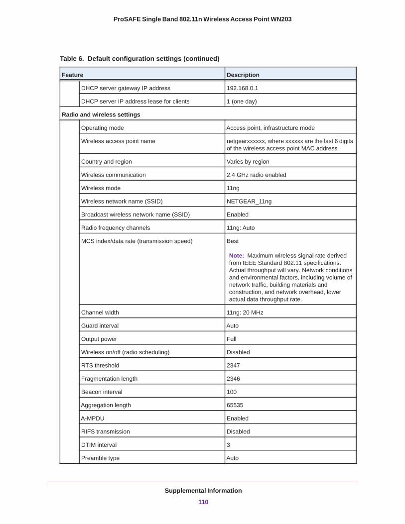
ProSAFE Single Band 802.11n Wireless Access Point WN203
DHCP server gateway IP address 192.168.0.1
DHCP server IP address lease for clients 1 (one day)
Radio and wireless settings
Operating mode Access point, infrastructure mode
Wireless access point name netgearxxxxxx, where xxxxxx are the last 6 digits of the wireless access point MAC address
Country and region Varies by region
Wireless communication 2.4 GHz radio enabled
Wireless mode 11ng
Wireless network name (SSID) NETGEAR_11ng
Broadcast wireless network name (SSID) Enabled
Radio frequency channels 11ng: Auto
MCS index/data rate (transmission speed) Best
Note: Maximum wireless signal rate derived from IEEE Standard 802.11 specifications. Actual throughput will vary. Network conditions and environmental factors, including volume of network traffic, building materials and construction, and network overhead, lower actual data throughput rate.
Channel width 11ng: 20 MHz
Guard interval Auto
Output power Full
Wireless on/off (radio scheduling) Disabled
RTS threshold 2347
Fragmentation length 2346
Beacon interval 100
Aggregation length 65535
A-MPDU Enabled
RIFS transmission Disabled
DTIM interval 3
Preamble type Auto
Table 6. Default configuration settings (continued)
Feature Description
Supplemental Information
110
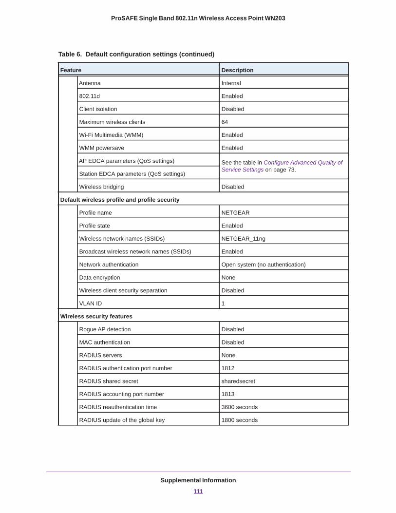
ProSAFE Single Band 802.11n Wireless Access Point WN203
Antenna Internal
802.11d Enabled
Client isolation Disabled
Maximum wireless clients 64
Wi-Fi Multimedia (WMM) Enabled
WMM powersave Enabled
AP EDCA parameters (QoS settings) See the table in Configure Advanced Quality of Service Settings on page 73.
Station EDCA parameters (QoS settings)
Wireless bridging Disabled
Default wireless profile and profile security
Profile name NETGEAR
Profile state Enabled
Wireless network names (SSIDs) NETGEAR_11ng
Broadcast wireless network names (SSIDs) Enabled
Network authentication Open system (no authentication)
Data encryption None
Wireless client security separation Disabled
VLAN ID 1
Wireless security features
Rogue AP detection Disabled
MAC authentication Disabled
RADIUS servers None
RADIUS authentication port number 1812
RADIUS shared secret sharedsecret
RADIUS accounting port number 1813
RADIUS reauthentication time 3600 seconds
RADIUS update of the global key 1800 seconds
Table 6. Default configuration settings (continued)
Feature Description
Supplemental Information
111
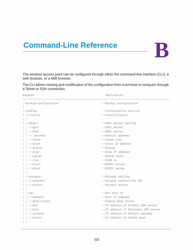
B
B. Command-Line ReferenceThe wireless access point can be configured through either the command-line interface (CLI), a web browser, or a MIB browser.
The CLI allows viewing and modification of the configuration from a terminal or computer through a Telnet or SSH connection.
Keyword Description-------------------------------------------------------------------------------------------|-backup-configuration --Backup configuration ||-config> --Configuration setting| |-country --Country/region| || |-dhcp> --DHCP server setting| | |-dns1 --DNS1 server| | |-dns2 --DNS2 server| | |- gateway --Default gateway | | |-lease --Lease time| | |-start --Start IP address| | |-status --Status| | |-stop --Stop IP address| | |-subnet --Subnet mask| | |-vlan --VLAN id| | |-wins1 --WINS1 server| | |-wins2 --WINS2 server| || |-hotspot> --Hotspot setting| | |-redirect --Hotspot redirection URL| | |-status --Hotspot status| || |-ip> --Set host IP| | |-address --Host IP address| | |-dhcp-client --Enable dhcp client| | |-dns --IP address of Primary DNS server| | |-dns2 --IP address of Secondary DNS server| | |-gateway --IP address of default gateway| | |-subnet --IP address of Subnet mask| |
112

ProSAFE Single Band 802.11n Wireless Access Point WN203
| |-name --Access point name| | | |-no> --Reset| | |-dhcp> --DHCP server settings| | | |-dns1 --DNS1 server| | | |-dns2 --DNS2 server| | | |-wins1 --WINS1 server| | | |-wins2 --WINS1 server| | |-radius> --RADIUS server setting| | | |-primary> --Primary RADIUS server| | | | |-auth port --Authentication port| | | | |-auth secret --Authentication shared secret| | | | |-auth server --Authentication server IP| | | | |-acct port --Accounting port| | | | |-acct secret --Accounting shared secret| | | | |-acct server --Accounting server IP| | | |-secondary> --Secondary RADIUS server| | | | |-auth port --Authentication port| | | | |-auth secret --Authentication shared secret| | | | |-auth server --Authentication server IP| | | | |-acct port --Accounting port| | | | |-acct secret --Accounting shared secret| | | | |-acct server --Accounting server IP | |-radio> --Wireless LAN interface setting| | |-2.4 --2.4 GHz wireless LAN status| | |-2.4> --2.4 GHz wireless LAN interface setting| | | |-80211d --802.11D| | | |-aggregation-length --Aggregated packet size| | | |-ampdu --Aggregated MAC Protocol Data Unit| | | |-beacon-interval --Wireless beacon period in TU(1024 us)| | | |-channel --Wireless channel (depends on country| | | | and wireless mode)| | | |-channel auto --Set wireless channel to auto mode| | | |-channel-width --Wireless channel width| | | |-client-isolation --Client isolation status| | | |-data-rate> --Wireless transmission date rate| | | | |-best --Best date rate| | | | |-mcs --Date rate (MCS Index)| | | | |-rate --Date rate (in Mbps)| | | |-dtim --Wireless DTIM period in beacon interval| | | |-fragmentation-length --Wireless fragmentation threshold| | | |-guard-interval --Guard interval (from interference from | | | | other transmissions)| | | |-macacl add --Add wireless access control (ACL)| | | |-macacl del --Delete wireless access control (ACL)| | | |-macacl del all --Delete wireless access control (ACL) | | | | database| | | |-max-client --Maximum client| | | |-power --Output power
Command-Line Reference
113

ProSAFE Single Band 802.11n Wireless Access Point WN203
| | | |-preamble-type --Wireless preamble (only effect on| | | | 802.11b rates)| | | |-rifs-transmission --Enable successive frame transmission| | | | at different transmit| | | |-rogue-ap-detection --Enable rogue access point detection| | | |-rogue-ap-detection knownap add --Add rogue access point detection | | | |-rogue-ap-detection knownap del MAC --Delete rogue access point detection | | | |-rogue-ap-detection knownap del all --Delete rogue access point detection| | | | Database| | | |-rts-threshold --Wireless RTS/CTS threshold| | | |-wds --Wireless Bridge status| | | |-wds> --Wireless Bridge setting| | | | |-1 --1st WDS security profile status| | | | |-1> --1st security profile| | | | | |-authentication --Authentication type| | | | | |-authentication open encryption --Data encryption| | | | | |-name --Profile name| | | | | |-remote-mac --Remote MAC| | | | | |-wep-key --Wireless WEP key| | | | | |-wpa-passphrase --Wireless WPA passphrase| | | | || | | | |-2 --2nd WDS security profile status | | | | |-2> --2nd security profile| | | | | |-authentication --Authentication type| | | | | |-authentication open encryption --Data encryption| | | | | |-name --Profile name| | | | | |-remote-mac --Remote MAC| | | | | |-wep-key --Wireless WEP key| | | | | |-wpa-passphrase --Wireless WPA passphrase| | | | | | | | | |-3 --3rd WDS security profile status| | | | |-3> --3rd security profile| | | | | |-authentication --Authentication type| | | | | |-authentication open encryption --Data encryption| | | | | |-name --Profile name| | | | | |-remote-mac --Remote MAC| | | | | |-wep-key --Wireless WEP key| | | | | |-wpa-passphrase --Wireless WPA passphrase| | | | | | | | | |-4 --4th WDS security profile status| | | | |-4> --4th security profile| | | | | |-authentication --Authentication type| | | | | |-authentication open encryption --Data encryption| | | | | |-name --Profile name| | | | | |-remote-mac --Remote MAC| | | | | |-wep-key --Wireless WEP key| | | | | |-wpa-passphrase --Wireless WPA passphrase| | | |
Command-Line Reference
114
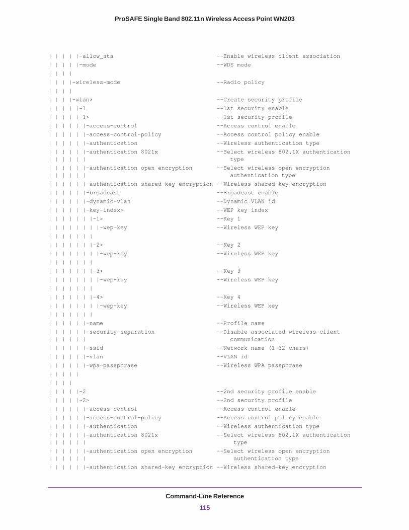
ProSAFE Single Band 802.11n Wireless Access Point WN203
| | | | |-allow_sta --Enable wireless client association| | | | |-mode --WDS mode| | | || | | |-wireless-mode --Radio policy| | | || | | |-wlan> --Create security profile| | | | |-1 --1st security enable| | | | |-1> --1st security profile| | | | | |-access-control --Access control enable| | | | | |-access-control-policy --Access control policy enable| | | | | |-authentication --Wireless authentication type| | | | | |-authentication 8021x --Select wireless 802.1X authentication | | | | | | type| | | | | |-authentication open encryption --Select wireless open encryption | | | | | | authentication type| | | | | |-authentication shared-key encryption --Wireless shared-key encryption| | | | | |-broadcast --Broadcast enable| | | | | |-dynamic-vlan --Dynamic VLAN id| | | | | |-key-index> --WEP key index| | | | | | |-1> --Key 1| | | | | | | |-wep-key --Wireless WEP key| | | | | | || | | | | | |-2> --Key 2| | | | | | | |-wep-key --Wireless WEP key| | | | | | || | | | | | |-3> --Key 3| | | | | | | |-wep-key --Wireless WEP key| | | | | | || | | | | | |-4> --Key 4| | | | | | | |-wep-key --Wireless WEP key| | | | | | || | | | | |-name --Profile name| | | | | |-security-separation --Disable associated wireless client | | | | | | communication| | | | | |-ssid --Network name (1-32 chars)| | | | | |-vlan --VLAN id| | | | | |-wpa-passphrase --Wireless WPA passphrase| | | | | | | | || | | | |-2 --2nd security profile enable| | | | |-2> --2nd security profile| | | | | |-access-control --Access control enable| | | | | |-access-control-policy --Access control policy enable| | | | | |-authentication --Wireless authentication type| | | | | |-authentication 8021x --Select wireless 802.1X authentication | | | | | | type| | | | | |-authentication open encryption --Select wireless open encryption | | | | | | authentication type| | | | | |-authentication shared-key encryption --Wireless shared-key encryption
Command-Line Reference
115
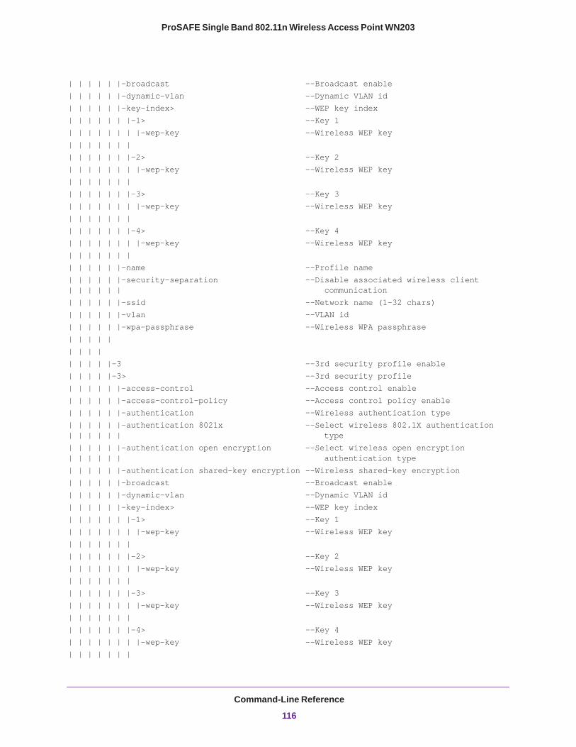
ProSAFE Single Band 802.11n Wireless Access Point WN203
| | | | | |-broadcast --Broadcast enable| | | | | |-dynamic-vlan --Dynamic VLAN id| | | | | |-key-index> --WEP key index| | | | | | |-1> --Key 1| | | | | | | |-wep-key --Wireless WEP key| | | | | | || | | | | | |-2> --Key 2| | | | | | | |-wep-key --Wireless WEP key| | | | | | || | | | | | |-3> --Key 3| | | | | | | |-wep-key --Wireless WEP key| | | | | | || | | | | | |-4> --Key 4| | | | | | | |-wep-key --Wireless WEP key| | | | | | || | | | | |-name --Profile name| | | | | |-security-separation --Disable associated wireless client | | | | | | communication| | | | | |-ssid --Network name (1-32 chars)| | | | | |-vlan --VLAN id| | | | | |-wpa-passphrase --Wireless WPA passphrase| | | | | | | | || | | | |-3 --3rd security profile enable| | | | |-3> --3rd security profile| | | | | |-access-control --Access control enable| | | | | |-access-control-policy --Access control policy enable| | | | | |-authentication --Wireless authentication type| | | | | |-authentication 8021x --Select wireless 802.1X authentication | | | | | | type| | | | | |-authentication open encryption --Select wireless open encryption | | | | | | authentication type| | | | | |-authentication shared-key encryption --Wireless shared-key encryption| | | | | |-broadcast --Broadcast enable| | | | | |-dynamic-vlan --Dynamic VLAN id| | | | | |-key-index> --WEP key index| | | | | | |-1> --Key 1| | | | | | | |-wep-key --Wireless WEP key| | | | | | || | | | | | |-2> --Key 2| | | | | | | |-wep-key --Wireless WEP key| | | | | | || | | | | | |-3> --Key 3| | | | | | | |-wep-key --Wireless WEP key| | | | | | || | | | | | |-4> --Key 4| | | | | | | |-wep-key --Wireless WEP key| | | | | | |
Command-Line Reference
116
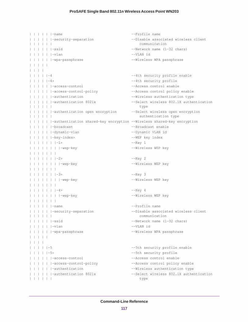
ProSAFE Single Band 802.11n Wireless Access Point WN203
| | | | | |-name --Profile name| | | | | |-security-separation --Disable associated wireless client | | | | | | communication| | | | | |-ssid --Network name (1-32 chars)| | | | | |-vlan --VLAN id| | | | | |-wpa-passphrase --Wireless WPA passphrase| | | | | | | | || | | | |-4 --4th security profile enable| | | | |-4> --4th security profile| | | | | |-access-control --Access control enable| | | | | |-access-control-policy --Access control policy enable| | | | | |-authentication --Wireless authentication type| | | | | |-authentication 8021x --Select wireless 802.1X authentication | | | | | | type| | | | | |-authentication open encryption --Select wireless open encryption | | | | | | authentication type| | | | | |-authentication shared-key encryption --Wireless shared-key encryption| | | | | |-broadcast --Broadcast enable| | | | | |-dynamic-vlan --Dynamic VLAN id| | | | | |-key-index> --WEP key index| | | | | | |-1> --Key 1| | | | | | | |-wep-key --Wireless WEP key| | | | | | || | | | | | |-2> --Key 2| | | | | | | |-wep-key --Wireless WEP key| | | | | | || | | | | | |-3> --Key 3| | | | | | | |-wep-key --Wireless WEP key| | | | | | || | | | | | |-4> --Key 4| | | | | | | |-wep-key --Wireless WEP key| | | | | | || | | | | |-name --Profile name| | | | | |-security-separation --Disable associated wireless client | | | | | | communication| | | | | |-ssid --Network name (1-32 chars)| | | | | |-vlan --VLAN id| | | | | |-wpa-passphrase --Wireless WPA passphrase| | | | | | | | || | | | |-5 --5th security profile enable| | | | |-5> --5th security profile| | | | | |-access-control --Access control enable| | | | | |-access-control-policy --Access control policy enable| | | | | |-authentication --Wireless authentication type| | | | | |-authentication 8021x --Select wireless 802.1X authentication | | | | | | type
Command-Line Reference
117
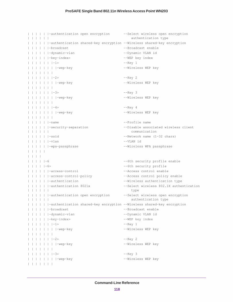
ProSAFE Single Band 802.11n Wireless Access Point WN203
| | | | | |-authentication open encryption --Select wireless open encryption | | | | | | authentication type| | | | | |-authentication shared-key encryption --Wireless shared-key encryption| | | | | |-broadcast --Broadcast enable| | | | | |-dynamic-vlan --Dynamic VLAN id| | | | | |-key-index> --WEP key index| | | | | | |-1> --Key 1| | | | | | | |-wep-key --Wireless WEP key| | | | | | || | | | | | |-2> --Key 2| | | | | | | |-wep-key --Wireless WEP key| | | | | | || | | | | | |-3> --Key 3| | | | | | | |-wep-key --Wireless WEP key| | | | | | || | | | | | |-4> --Key 4| | | | | | | |-wep-key --Wireless WEP key| | | | | | || | | | | |-name --Profile name| | | | | |-security-separation --Disable associated wireless client | | | | | | communication| | | | | |-ssid --Network name (1-32 chars)| | | | | |-vlan --VLAN id| | | | | |-wpa-passphrase --Wireless WPA passphrase| | | | | | | | || | | | |-6 --6th security profile enable| | | | |-6> --6th security profile| | | | | |-access-control --Access control enable| | | | | |-access-control-policy --Access control policy enable| | | | | |-authentication --Wireless authentication type| | | | | |-authentication 8021x --Select wireless 802.1X authentication | | | | | | type| | | | | |-authentication open encryption --Select wireless open encryption | | | | | | authentication type| | | | | |-authentication shared-key encryption --Wireless shared-key encryption| | | | | |-broadcast --Broadcast enable| | | | | |-dynamic-vlan --Dynamic VLAN id| | | | | |-key-index> --WEP key index| | | | | | |-1> --Key 1| | | | | | | |-wep-key --Wireless WEP key| | | | | | || | | | | | |-2> --Key 2| | | | | | | |-wep-key --Wireless WEP key| | | | | | || | | | | | |-3> --Key 3| | | | | | | |-wep-key --Wireless WEP key| | | | | | |
Command-Line Reference
118

ProSAFE Single Band 802.11n Wireless Access Point WN203
| | | | | | |-4> --Key 4| | | | | | | |-wep-key --Wireless WEP key| | | | | | || | | | | |-name --Profile name| | | | | |-security-separation --Disable associated wireless client | | | | | | communication| | | | | |-ssid --Network name (1-32 chars)| | | | | |-vlan --VLAN id| | | | | |-wpa-passphrase --Wireless WPA passphrase| | | | | | | | || | | | |-7 --7th security profile enable| | | | |-7> --7th security profile| | | | | |-access-control --Access control enable| | | | | |-access-control-policy --Access control policy enable| | | | | |-authentication --Wireless authentication type| | | | | |-authentication 8021x --Select wireless 802.1X authentication | | | | | | type| | | | | |-authentication open encryption --Select wireless open encryption | | | | | | authentication type| | | | | |-authentication shared-key encryption --Wireless shared-key encryption| | | | | |-broadcast --Broadcast enable| | | | | |-dynamic-vlan --Dynamic VLAN id| | | | | |-key-index> --WEP key index| | | | | | |-1> --Key 1| | | | | | | |-wep-key --Wireless WEP key| | | | | | || | | | | | |-2> --Key 2| | | | | | | |-wep-key --Wireless WEP key| | | | | | || | | | | | |-3> --Key 3| | | | | | | |-wep-key --Wireless WEP key| | | | | | || | | | | | |-4> --Key 4| | | | | | | |-wep-key --Wireless WEP key| | | | | | || | | | | |-name --Profile name| | | | | |-security-separation --Disable associated wireless client | | | | | | communication| | | | | |-ssid --Network name (1-32 chars)| | | | | |-vlan --VLAN id| | | | | |-wpa-passphrase --Wireless WPA passphrase| | | | | | | | || | | | |-8 --8th security profile enable| | | | |-8> --8th security profile| | | | | |-access-control --Access control enable| | | | | |-access-control-policy --Access control policy enable| | | | | |-authentication --Wireless authentication type
Command-Line Reference
119
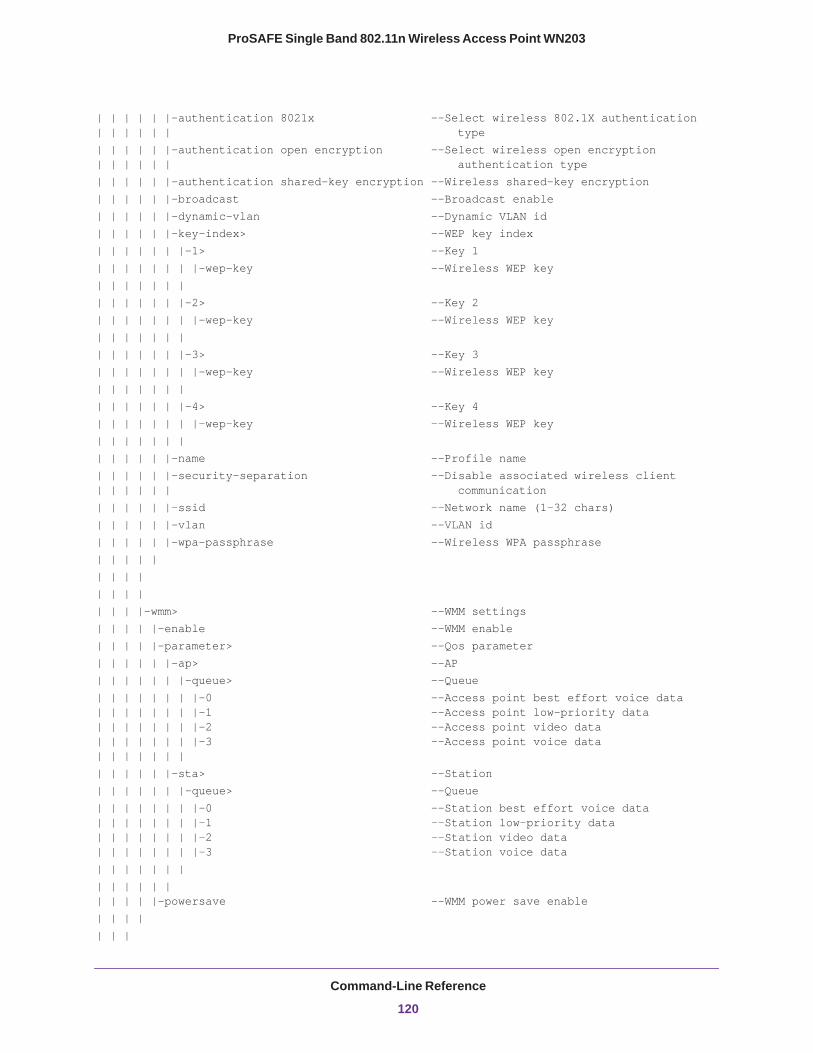
ProSAFE Single Band 802.11n Wireless Access Point WN203
| | | | | |-authentication 8021x --Select wireless 802.1X authentication | | | | | | type| | | | | |-authentication open encryption --Select wireless open encryption | | | | | | authentication type| | | | | |-authentication shared-key encryption --Wireless shared-key encryption| | | | | |-broadcast --Broadcast enable| | | | | |-dynamic-vlan --Dynamic VLAN id| | | | | |-key-index> --WEP key index| | | | | | |-1> --Key 1| | | | | | | |-wep-key --Wireless WEP key| | | | | | || | | | | | |-2> --Key 2| | | | | | | |-wep-key --Wireless WEP key| | | | | | || | | | | | |-3> --Key 3| | | | | | | |-wep-key --Wireless WEP key| | | | | | || | | | | | |-4> --Key 4| | | | | | | |-wep-key --Wireless WEP key| | | | | | || | | | | |-name --Profile name| | | | | |-security-separation --Disable associated wireless client | | | | | | communication| | | | | |-ssid --Network name (1-32 chars)| | | | | |-vlan --VLAN id| | | | | |-wpa-passphrase --Wireless WPA passphrase| | | | | | | | || | | || | | |-wmm> --WMM settings| | | | |-enable --WMM enable| | | | |-parameter> --Qos parameter| | | | | |-ap> --AP| | | | | | |-queue> --Queue| | | | | | | |-0 --Access point best effort voice data | | | | | | | |-1 --Access point low-priority data | | | | | | | |-2 --Access point video data | | | | | | | |-3 --Access point voice data | | | | | | || | | | | |-sta> --Station| | | | | | |-queue> --Queue| | | | | | | |-0 --Station best effort voice data | | | | | | | |-1 --Station low-priority data | | | | | | | |-2 --Station video data | | | | | | | |-3 --Station voice data| | | | | | || | | | | | | | | | |-powersave --WMM power save enable| | | | | | |
Command-Line Reference
120

ProSAFE Single Band 802.11n Wireless Access Point WN203
| || |-radius> --RADIUS server settings | | |-primary> --Primary RADIUS server| | | |-auth port> --Authentication port| | | |-auth secret> --Authentication Shared secret | | | |-auth server> --Authentication server| | | |-acct port> --Accounting port | | | |-acct secret> --Accounting Shared secret| | | |-acct server> --Accounting server | | || || | |-secondary> --Secondary RADIUS server | | | |-auth port> --Authentication port| | | |-auth secret> --Authentication Shared secret | | | |-auth server> --Authentication server| | | |-acct port> --Accounting port | | | |-acct secret> --Accounting Shared secret| | | |-acct server> --Accounting server | | || | | |-remote> --Remote access settings | | |-ssh --Enable remote access via SSH | | |-telnet --Enable remote access via Telnet| | | |-snmp-setting> --SNMP settings | | |-read community --SNMP Read Community | | |-read-write community --SNMP Read Write Community | | |-snmp-status --SNMP status | | |-trap community --SNMP Trap Community | | |-trap server --SNMP Trap Server IP address | | |-trap-port --SNMP Trap port| | | |-spanning-tree status --Enable spanning tree protocol | || |-syslog> --Syslog setting | | |-port --Syslog server port number | | |-server --Syslog server IP address | | |-status --Enable syslog client | | | |-time-settings> --Time Setting | | |-ntp> --NTP sever settings| | | |-client --Client enable| | | |-custom-server --Custom server enable| | | |-server --Server host name | | || | |-timezone --Time zone | | | |-vlan> --VLAN settings | | |-management-vlan --Management VLAN id| | |-untagged-vlan id --Untagged VLAN id | | |-untagged-vlan-status --Untagged VLAN status | ||
Command-Line Reference
121
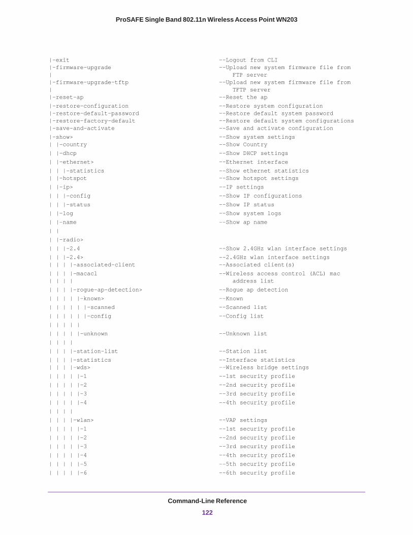
ProSAFE Single Band 802.11n Wireless Access Point WN203
|-exit --Logout from CLI |-firmware-upgrade --Upload new system firmware file from | FTP server |-firmware-upgrade-tftp --Upload new system firmware file from | TFTP server |-reset-ap --Reset the ap|-restore-configuration --Restore system configuration |-restore-default-password --Restore default system password |-restore-factory-default --Restore default system configurations |-save-and-activate –-Save and activate configuration|-show> --Show system settings | |-country --Show Country| |-dhcp --Show DHCP settings| |-ethernet> --Ethernet interface| | |-statistics --Show ethernet statistics | |-hotspot --Show hotspot settings| |-ip> --IP settings| | |-config --Show IP configurations| | |-status --Show IP status| |-log --Show system logs| |-name --Show ap name| || |-radio>| | |-2.4 --Show 2.4GHz wlan interface settings| | |-2.4> --2.4GHz wlan interface settings | | | |-associated-client --Associated client(s)| | | |-macacl --Wireless access control (ACL) mac | | | | address list| | | |-rogue-ap-detection> --Rogue ap detection| | | | |-known> --Known| | | | | |-scanned --Scanned list| | | | | |-config --Config list| | | | || | | | |-unknown --Unknown list| | | || | | |-station-list --Station list| | | |-statistics --Interface statistics | | | |-wds> --Wireless bridge settings| | | | |-1 --1st security profile| | | | |-2 --2nd security profile| | | | |-3 --3rd security profile| | | | |-4 --4th security profile| | | || | | |-wlan> --VAP settings| | | | |-1 --1st security profile| | | | |-2 --2nd security profile| | | | |-3 --3rd security profile| | | | |-4 --4th security profile| | | | |-5 --5th security profile| | | | |-6 --6th security profile
Command-Line Reference
122
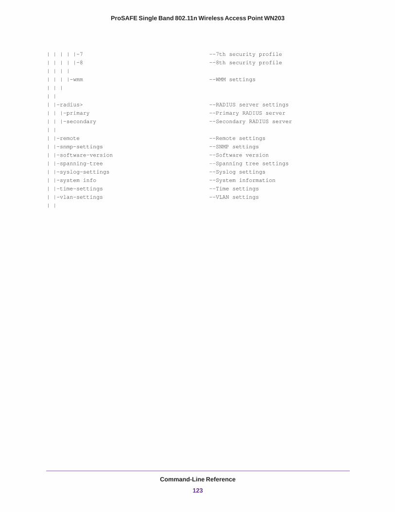
ProSAFE Single Band 802.11n Wireless Access Point WN203
| | | | |-7 --7th security profile| | | | |-8 --8th security profile| | | || | | |-wmm --WMM settings| | || || |-radius> --RADIUS server settings| | |-primary --Primary RADIUS server| | |-secondary --Secondary RADIUS server | || |-remote --Remote settings| |-snmp-settings --SNMP settings| |-software-version --Software version| |-spanning-tree --Spanning tree settings| |-syslog-settings --Syslog settings| |-system info --System information| |-time-settings --Time settings| |-vlan-settings --VLAN settings| |
Command-Line Reference
123

ProSAFE Single Band 802.11n Wireless Access Point WN203
Command-Line Reference
124
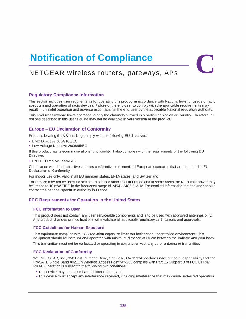
C
C. Notification of ComplianceNETGEAR wireless routers, gateways, APsRegulatory Compliance InformationThis section includes user requirements for operating this product in accordance with National laws for usage of radio spectrum and operation of radio devices. Failure of the end-user to comply with the applicable requirements may result in unlawful operation and adverse action against the end-user by the applicable National regulatory authority.This product's firmware limits operation to only the channels allowed in a particular Region or Country. Therefore, all options described in this user's guide may not be available in your version of the product.
Europe – EU Declaration of Conformity Products bearing the marking comply with the following EU directives:• EMC Directive 2004/108/EC• Low Voltage Directive 2006/95/ECIf this product has telecommunications functionality, it also complies with the requirements of the following EU Directive:• R&TTE Directive 1999/5/ECCompliance with these directives implies conformity to harmonized European standards that are noted in the EU Declaration of Conformity. For indoor use only. Valid in all EU member states, EFTA states, and Switzerland. This device may not be used for setting up outdoor radio links in France and in some areas the RF output power may be limited to 10 mW EIRP in the frequency range of 2454 - 2483.5 MHz. For detailed information the end-user should contact the national spectrum authority in France.
FCC Requirements for Operation in the United States
FCC Information to UserThis product does not contain any user serviceable components and is to be used with approved antennas only. Any product changes or modifications will invalidate all applicable regulatory certifications and approvals.
FCC Guidelines for Human ExposureThis equipment complies with FCC radiation exposure limits set forth for an uncontrolled environment. This equipment should be installed and operated with minimum distance of 20 cm between the radiator and your body. This transmitter must not be co-located or operating in conjunction with any other antenna or transmitter.
FCC Declaration of ConformityWe, NETGEAR, Inc., 350 East Plumeria Drive, San Jose, CA 95134, declare under our sole responsibility that the ProSAFE Single Band 802.11n Wireless Access Point WN203 complies with Part 15 Subpart B of FCC CFR47 Rules. Operation is subject to the following two conditions:
• This device may not cause harmful interference, and• This device must accept any interference received, including interference that may cause undesired operation.
125
ProSAFE Single Band 802.11n Wireless Access Point WN203
FCC Radio Frequency Interference Warnings & InstructionsThis equipment has been tested and found to comply with the limits for a Class B digital device, pursuant to Part 15 of the FCC Rules. These limits are designed to provide reasonable protection against harmful interference in a residential installation. This equipment uses and can radiate radio frequency energy and, if not installed and used in accordance with the instructions, may cause harmful interference to radio communications. However, there is no guarantee that interference will not occur in a particular installation. If this equipment does cause harmful interference to radio or television reception, which can be determined by turning the equipment off and on, the user is encouraged to try to correct the interference by one or more of the following methods:
• Reorient or relocate the receiving antenna.• Increase the separation between the equipment and the receiver.• Connect the equipment into an electrical outlet on a circuit different from that which the radio receiver is
connected.• Consult the dealer or an experienced radio/TV technician for help.
FCC Caution• Any changes or modifications not expressly approved by the party responsible for compliance could void the
user’s authority to operate this equipment. • This device complies with Part 15 of the FCC Rules. Operation is subject to the following two conditions: (1) This
device may not cause harmful interference, and (2) this device must accept any interference received, including interference that may cause undesired operation.
• For product available in the USA and Canada market, only channel 1~11 can be operated. Selection of other channels is not possible.
• Pour les produits disponibles aux États-Unis / Canada du marché, seul le canal 1 à 11 peuvent être exploités. Sélection d'autres canaux n'est pas possible.
• This device and its antenna(s) must not be co-located or operation in conjunction with any other antenna or transmitter.
• Cet appareil et son antenne (s) ne doit pas être co-localisés ou fonctionnement en association avec une autre antenne ou transmetteur.
Industry CanadaThis device complies with RSS-210 of the Industry Canada Rules. Operation is subject to the following two conditions: (1) This device may not cause harmful interference, and (2) this device must accept any interference received, including interference that may cause undesired operation.
Caution:Ce dispositif est conforme à la norme CNR-210 d'Industrie Canada applicable aux appareils radio exempts de licence. Son fonctionnement est sujet aux deux conditions suivantes: (1) le dispositif ne doit pas produire de brouillage préjudiciable, et (2) ce dispositif doit accepter tout brouillage reçu, y compris un brouillage susceptible de provoquer un fonctionnement indésirable.
IMPORTANT NOTE: Radiation Exposure Statement:This equipment complies with IC radiation exposure limits set forth for an uncontrolled environment. This equipment should be installed and operated with minimum distance 20cm between the radiator & your body.
NOTE IMPORTANTE: Déclaration d'exposition aux radiations:Cet équipement est conforme aux limites d'exposition aux rayonnements IC établies pour un environnement non contrôlé. Cet équipement doit être installé et utilisé avec un minimum de 20 cm de distance entre la source de rayonnement et votre corps.
Notification of Compliance
126

ProSAFE Single Band 802.11n Wireless Access Point WN203
Interference Reduction TableThe table below shows the recommended minimum distance between NETGEAR equipment and household appliances to reduce interference (in feet and meters).
Household Appliance Recommended Minimum Distance(in feet and meters)
Microwave ovens 30 feet / 9 meters
Baby Monitor - Analog 20 feet / 6 meters
Baby Monitor - Digital 40 feet / 12 meters
Cordless phone - Analog 20 feet / 6 meters
Cordless phone - Digital 30 feet / 9 meters
Bluetooth devices 20 feet / 6 meters
ZigBee 20 feet / 6 meters
Notification of Compliance
127
Index
Numerics11b, 11bg, and 11ng wireless modes 262.4 GHz external antennas
connectors for 12enabling 72
64-bit, 128-bit, and 152-bit WEP 41802.11b/g/n and 802.11a/n
wireless adapters 16wireless settings 25–28
802.11d support 72802.1Q VLAN 9, 69
Aaccess control, wireless clients 40access, restricting by MAC address 32, 46accounting, RADIUS servers 45–46ActiveX 102activity log 96admin password
changing or restoring 61default 109
AES (Advanced Encryption Standard) 33, 43–44Aggregated MAC Protocol Data Unit (A-MPDU)
frames 72aggregation length 72AID (associated identifier) 95AIFS (Arbitration Inter-Frame Spacing) interval 74A-MPDU (Aggregated MAC Protocol Data Unit)
frames 72antennas
connecting external antennas 12switching between internal and external 72
Arbitration Inter-Frame Spacing (AIFS) interval 74associated identifier (AID) 95associations, wireless clients 98authentication
network 34RADIUS servers 45
autosensing over Ethernet 10
12
Bback panel 12background traffic
advanced QoS 73WMM QoS 50
backing up 57basic service set (BSS) 34basic service set identifier (BSSID)
configuring 36–44described 8, 32–34monitoring 94
beacon interval 71beacons, unknown access points 65best effort traffic
advanced QoS 73WMM QoS 50
bridging modes, wireless 75broadcast packets, transmitted and received 98broadcasting wireless network names (SSIDs)
802.11b/bg/ng modes 27security 32
browsers, recommended 18BSS (basic service set) 34BSSID (basic service set identifier)
configuring 36–44described 8, 32–34monitoring 94
bytes, received and transmittedEthernet connection 98wireless connection 96
CCarrier Sense Multiple Access (CSMA) 71Category 5 Ethernet cable 7channel width and offset (802.11ng) 28channels and frequencies
defaults 107selecting for 802.11b/bg/ng modes 27
channels, wireless spacing 25Clear to Send (CTS) packets 71CLI (command-line interface) commands 112
8

ProSAFE Single Band 802.11n Wireless Access Point WN203
clientsassociated, number of 98DHCP, enabling 23isolation, enabling 72maximum number 72monitoring 94NTP, enabling 21trusted 47wireless separation, enabling 34, 39
collision detection and collision avoidance, CSMA 71command-line interface (CLI) commands 112community names and traps, SNMP 53compliance, electromagnetic 108compliance, notification of 125configuration file, backing up or restoring 57connectors and ports, back panel 12country, wireless location 20CSMA (Carrier Sense Multiple Access) 71CTS (Clear to Send) packets 71cwMin (minimum contention window) and cwMax
(maximum contention window) values 74
Ddata encryption
WEP 41, 42WPA and WPA2 44
data rates802.11b/bg modes 28specifications for all modes 107
date and time, troubleshooting 105defaults
channels and frequencies 107DHCP gateway 24factory settings, list of 108–111factory settings, restoring 58IP address 18, 23, 93, 109ISP gateway 23login password 18, 109SNMP 52subnet mask 23, 109user name 18, 109
delivery traffic indication message (DTIM) interval 72DHCP (Dynamic Host Configuration Protocol) client and
server 23–25DNS (Domain Name System) servers 23–24DTIM (delivery traffic indication message) interval 72dynamic and static VLANs 39Dynamic Host Configuration Protocol (DHCP) client and
server 23–25
EEDCA (Enhanced Distributed Channel Access)
parameters 73–75electromagnetic compliance 108encryption
WEP 41, 42WPA and WPA2 44
environmental specifications 108ESS (extended service set) 34Ethernet cabling requirements 16Ethernet packets and bytes, received and transmitted 98extended service set (ESS) 34external antennas
connecting 12enabling 72
Ffactory default settings
list of 108–111restoring 58
firmwarebacking up 57factory defaults 58, 108–111restoring from backup file 58upgrading 55
firmware version, viewing 93flash memory 54fragmentation length 71frequencies and channels
defaults 107selecting for 802.11b/bg/ng modes 27
front panel 11FTP traffic
advanced QoS 73WMM QoS 50
Ggateways, ISP and DHCP 23–24generating keys, WEP 41Gigabit Ethernet (RJ-45) port 12graphical user interface (GUI)
described 19troubleshooting 102
guard interval (802.11ng) 28
Hhotspot server 70
129
ProSAFE Single Band 802.11n Wireless Access Point WN203
Iidle time 95importing known access points 64infrastructure mode 25installation order 16interference 15Internet browsing, troubleshooting 101IP addresses
default 18, 23, 93, 109DHCP and DNS servers 23–24DHCP WINS servers 24errors 16NTP servers 21requirements 16SNMP manager 53static for management computer 109syslog server 62TFTP server 56
isolating clients 72
JJava and Javascript 102
Kkey generation, WEP 42key update, RADIUS servers 46
LLAN
configuration requirements 16IP addresses 109troubleshooting 101
LAN LEDbehavior startup procedure 18described 12troubleshooting 101
LAN path, troubleshooting 103lease period, DHCP 25LEDs
behavior startup procedure 17described 12troubleshooting 100
legacy 802.1X (wireless security) 38, 42link test, wireless bridging 80, 84, 89local MAC addresses 47location, country and region 20logging activities 96logging in 18login URL, name, and password 109
losing wireless connection 48
MMAC addresses
default, wireless access point 20Ethernet port 92known access points 66restricting access by 32, 46unknown access points 65wireless card 92
management VLAN 68management, remote options 52maximum burst value 74maximum contention window (cwMax) value 74maximum number of clients 72MCS (Modulation and Coding Scheme)
index and data rate 802.11ng 28minimum contention window (cwMin) value 74Modulation and Coding Scheme (MCS) 28multicast packets, transmitted and received 98
Nnames
firmware file 56NTP server 21profiles 38SNMP communities 52wireless access point 20wireless network (SSID) 27
NetBIOS name 20network authentication 34network configuration, troubleshooting 104network integrity check 23Network Time Protocol (NTP), client and server 21network traffic statistics, viewing 97
Oopen system (no security) 38, 40operating frequencies 107operating modes 9order of installation and configuration 16output power radio 28
Ppackage contents 7packets, received and transmitted 98passphrase
WEP 41
130
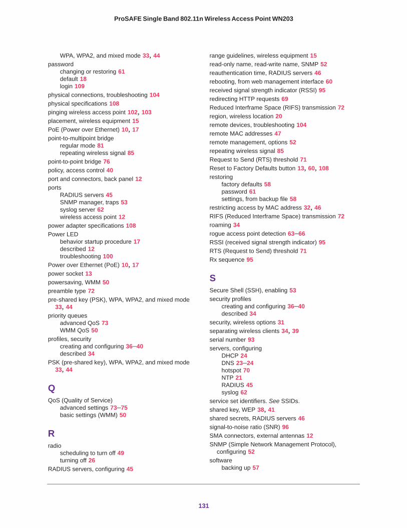
ProSAFE Single Band 802.11n Wireless Access Point WN203
WPA, WPA2, and mixed mode 33, 44password
changing or restoring 61default 18login 109
physical connections, troubleshooting 104physical specifications 108pinging wireless access point 102, 103placement, wireless equipment 15PoE (Power over Ethernet) 10, 17point-to-multipoint bridge
regular mode 81repeating wireless signal 85
point-to-point bridge 76policy, access control 40port and connectors, back panel 12ports
RADIUS servers 45SNMP manager, traps 53syslog server 62wireless access point 12
power adapter specifications 108Power LED
behavior startup procedure 17described 12troubleshooting 100
Power over Ethernet (PoE) 10, 17power socket 13powersaving, WMM 50preamble type 72pre-shared key (PSK), WPA, WPA2, and mixed mode
33, 44priority queues
advanced QoS 73WMM QoS 50
profiles, securitycreating and configuring 36–40described 34
PSK (pre-shared key), WPA, WPA2, and mixed mode 33, 44
QQoS (Quality of Service)
advanced settings 73–75basic settings (WMM) 50
Rradio
scheduling to turn off 49turning off 26
RADIUS servers, configuring 45
range guidelines, wireless equipment 15read-only name, read-write name, SNMP 52reauthentication time, RADIUS servers 46rebooting, from web management interface 60received signal strength indicator (RSSI) 95redirecting HTTP requests 69Reduced Interframe Space (RIFS) transmission 72region, wireless location 20remote devices, troubleshooting 104remote MAC addresses 47remote management, options 52repeating wireless signal 85Request to Send (RTS) threshold 71Reset to Factory Defaults button 13, 60, 108restoring
factory defaults 58password 61settings, from backup file 58
restricting access by MAC address 32, 46RIFS (Reduced Interframe Space) transmission 72roaming 34rogue access point detection 63–66RSSI (received signal strength indicator) 95RTS (Request to Send) threshold 71Rx sequence 95
SSecure Shell (SSH), enabling 53security profiles
creating and configuring 36–40described 34
security, wireless options 31separating wireless clients 34, 39serial number 93servers, configuring
DHCP 24DNS 23–24hotspot 70NTP 21RADIUS 45syslog 62
service set identifiers. See SSIDs.shared key, WEP 38, 41shared secrets, RADIUS servers 46signal-to-noise ratio (SNR) 96SMA connectors, external antennas 12SNMP (Simple Network Management Protocol),
configuring 52software
backing up 57
131
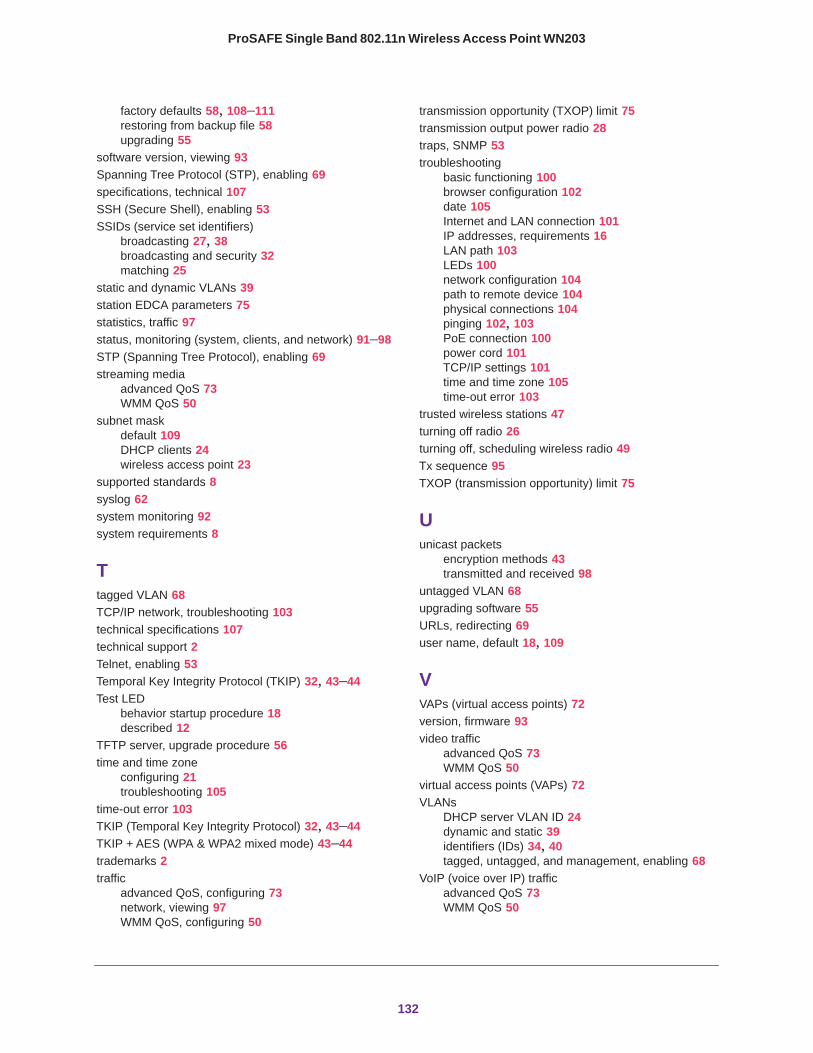
ProSAFE Single Band 802.11n Wireless Access Point WN203
factory defaults 58, 108–111restoring from backup file 58upgrading 55
software version, viewing 93Spanning Tree Protocol (STP), enabling 69specifications, technical 107SSH (Secure Shell), enabling 53SSIDs (service set identifiers)
broadcasting 27, 38broadcasting and security 32matching 25
static and dynamic VLANs 39station EDCA parameters 75statistics, traffic 97status, monitoring (system, clients, and network) 91–98STP (Spanning Tree Protocol), enabling 69streaming media
advanced QoS 73WMM QoS 50
subnet maskdefault 109DHCP clients 24wireless access point 23
supported standards 8syslog 62system monitoring 92system requirements 8
Ttagged VLAN 68TCP/IP network, troubleshooting 103technical specifications 107technical support 2Telnet, enabling 53Temporal Key Integrity Protocol (TKIP) 32, 43–44Test LED
behavior startup procedure 18described 12
TFTP server, upgrade procedure 56time and time zone
configuring 21troubleshooting 105
time-out error 103TKIP (Temporal Key Integrity Protocol) 32, 43–44TKIP + AES (WPA & WPA2 mixed mode) 43–44trademarks 2traffic
advanced QoS, configuring 73network, viewing 97WMM QoS, configuring 50
transmission opportunity (TXOP) limit 75transmission output power radio 28traps, SNMP 53troubleshooting
basic functioning 100browser configuration 102date 105Internet and LAN connection 101IP addresses, requirements 16LAN path 103LEDs 100network configuration 104path to remote device 104physical connections 104pinging 102, 103PoE connection 100power cord 101TCP/IP settings 101time and time zone 105time-out error 103
trusted wireless stations 47turning off radio 26turning off, scheduling wireless radio 49Tx sequence 95TXOP (transmission opportunity) limit 75
Uunicast packets
encryption methods 43transmitted and received 98
untagged VLAN 68upgrading software 55URLs, redirecting 69user name, default 18, 109
VVAPs (virtual access points) 72version, firmware 93video traffic
advanced QoS 73WMM QoS 50
virtual access points (VAPs) 72VLANs
DHCP server VLAN ID 24dynamic and static 39identifiers (IDs) 34, 40tagged, untagged, and management, enabling 68
VoIP (voice over IP) trafficadvanced QoS 73WMM QoS 50
132
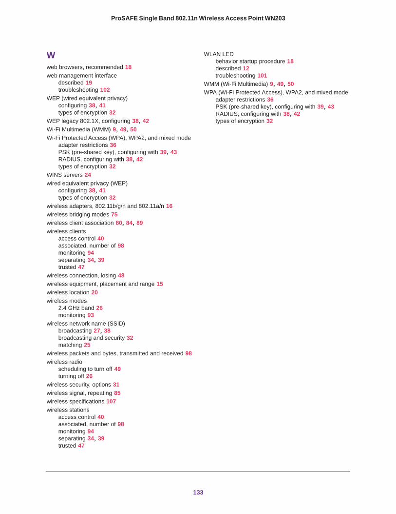
ProSAFE Single Band 802.11n Wireless Access Point WN203
Wweb browsers, recommended 18web management interface
described 19troubleshooting 102
WEP (wired equivalent privacy)configuring 38, 41types of encryption 32
WEP legacy 802.1X, configuring 38, 42Wi-Fi Multimedia (WMM) 9, 49, 50Wi-Fi Protected Access (WPA), WPA2, and mixed mode
adapter restrictions 36PSK (pre-shared key), configuring with 39, 43RADIUS, configuring with 38, 42types of encryption 32
WINS servers 24wired equivalent privacy (WEP)
configuring 38, 41types of encryption 32
wireless adapters, 802.11b/g/n and 802.11a/n 16wireless bridging modes 75wireless client association 80, 84, 89wireless clients
access control 40associated, number of 98monitoring 94separating 34, 39trusted 47
wireless connection, losing 48wireless equipment, placement and range 15wireless location 20wireless modes
2.4 GHz band 26monitoring 93
wireless network name (SSID)broadcasting 27, 38broadcasting and security 32matching 25
wireless packets and bytes, transmitted and received 98wireless radio
scheduling to turn off 49turning off 26
wireless security, options 31wireless signal, repeating 85wireless specifications 107wireless stations
access control 40associated, number of 98monitoring 94separating 34, 39trusted 47
WLAN LEDbehavior startup procedure 18described 12troubleshooting 101
WMM (Wi-Fi Multimedia) 9, 49, 50WPA (Wi-Fi Protected Access), WPA2, and mixed mode
adapter restrictions 36PSK (pre-shared key), configuring with 39, 43RADIUS, configuring with 38, 42types of encryption 32
133


![Prosafe SE (PRS) · 6020 EmployeesWebsite Cyprus Exchange PRS [Oslo Stock Exchange] Industry Company Overview Prosafe SE (Prosafe) is a provider of semi-submersible accommodation](https://img.pdfslide.net/doc/110x75/6015be59df313a7c091a033d/prosafe-se-prs-6020-employeeswebsite-cyprus-exchange-prs-oslo-stock-exchange.jpg)