Embed Size (px)
Citation preview
Dual Tubing String Completions Casing Sharing Technology
Two-for-One-Wellbores
Improving the Economics of Stranded Hydrocarbon Deposit Tie-backs
for Wet or Dry Trees
Prospectus

2
New Method of Using Proven Technology
| www.oilfieldinnovations.com
This page intentionally left blank
3
Oilfield Innovations Limited, June 2017
PROSPECTUS |
Prospectus New Dual Flow Stream Casing Sharing Technology
by Clint Smitha and Bruce Tungetb
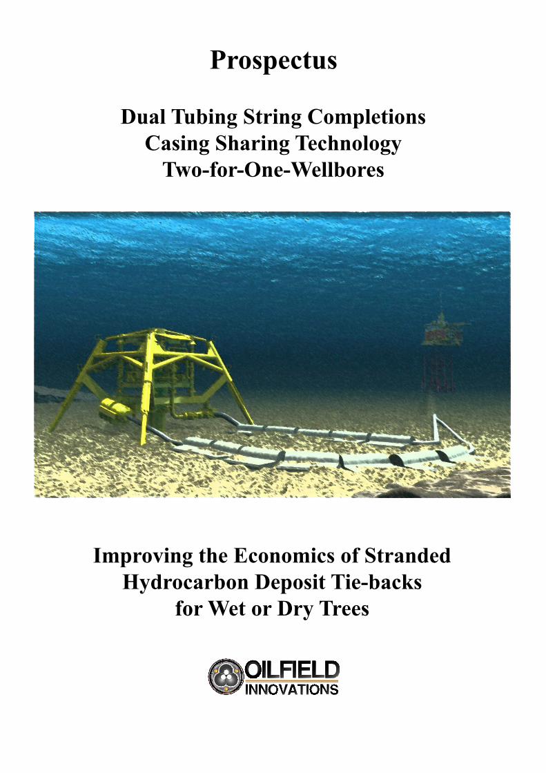
Reduce Costby 30%-50%
Abstract: The goal of cutting well costs by 30% to 50% is not new and has been recited by countless people who have never delivered for various reasons, including: ● inefficient interfaces between Operators who do not invest in new technology and Service Companies who don’t benefit from developing new technology, ● resistance by a workforce who fear redundancy comes with change, ● extremely low risk tolerances and ● fear of Health, Safety and Environmental (HSE) litigation. Also, “radical” changes to a system of well construction that uses standardised equipment which has been developed and optimised over a hundred years is not realistically possible in the short term. Accordingly, new technology solutions usable to cut well costs by 50% require maintaining current HSE risks while using a workforce resistant to change within a market controlled by Service Companies and Operators who neither cooperate nor want “radical” changes. Effectively, you need a widget that will, like magic, cut the cost of a well by 50% without any significant changes to the current system. The above
reasons have not stopped people from trying to reduce cost and, therefore, it is possible that a widget could bridge the gaps between existing technologies to dramatically improve economics. For example, extended reach drilling and multi-lateral well technologies have been developed and field proven precisely for delivering large well cost reductions. Unfortunately, despite having many of the necessary tools and occasionally attempting multi-lateral wells, Operators have not embraced multi-laterals for very good reasons, which include: Differing Downhole Pressures and a need for Separate Flow Streams, Limited Flow Areas for Conventional Dual String Completions, and Completion Complexity, Intervention Access, Well Barriers and Well Integrity. The 50% well cost reduction project proposed herein addresses these issues to facilitate wide-spread usage of proven multi-lateral and extended reach technologies by providing the “missing-link” between Operator’s needs and off-the-shelf technologies. Oilfield Innovations Limited (OILtd) have a “widget,” which we have nicknamed the “Magic Crossover,” that could be the “missing link” joining existing proven technology to deliver a 30% to 50% reduction in the cost of wells. Before describing our widget, it is important to understand why wide spread usage of multi-lateral technology is limited by existing dual string completion technology.
Introduction
Please note that the business case for the present new tech-nology is further discussed within an accompanying submit-tal.
With regard to geology, gock permeability is rarely con-stant across wells that access different parts of a large reser-voir and different wells can deplete at different rates or ac-cess reservoir compartments that are differently pressured.
If differently pressured flow streams are commingled, the flow stream of higher pressure will cross-flow into the lower pressured part of the reservoir and crowd-out or back-out the lower pressured flow stream. Production will be lost or de-layed and the net present value of the reservoir decreases.
Accordingly, Operators want separate tubing strings for separate reservoirs, separate reservoir compartments and/or
separate horizons of a single reservoir.
Unfortunately, the conventional practice of placing two tubing strings side-by-side within a single well bore, see Fig-ure 1 and Figure 2, restricts the cross sectional flow area and has proven to be unpopular with Operators.
Figure 1 compares a conventional dual string completion to OILtd’s widget, which uses tubing-in-tubing concentric flow and is called the Multi-Production-Injection Crossover (MPIX).
Parallel, or side-by-side, dual tubing strings are very in-efficient and the combined cross sectional flow area of both tubing strings are roughly the same as using a single larger diameter tubing string.
4
Terms of Reference
www.oilfieldinnovations.com
4 1/2” (12.6-ppf)3 1/2” (9.2-ppf)
9 5/8 (53.5-ppf)
7 5/8” (33.7-ppf)
7.03 in^2
7.03 in^212.3 in^2
18.6 in^2
MPIX = 30.9 in^ 22X Flow Area
Conventional =14.06 in^ 2+/- single 4 1/2” tubing
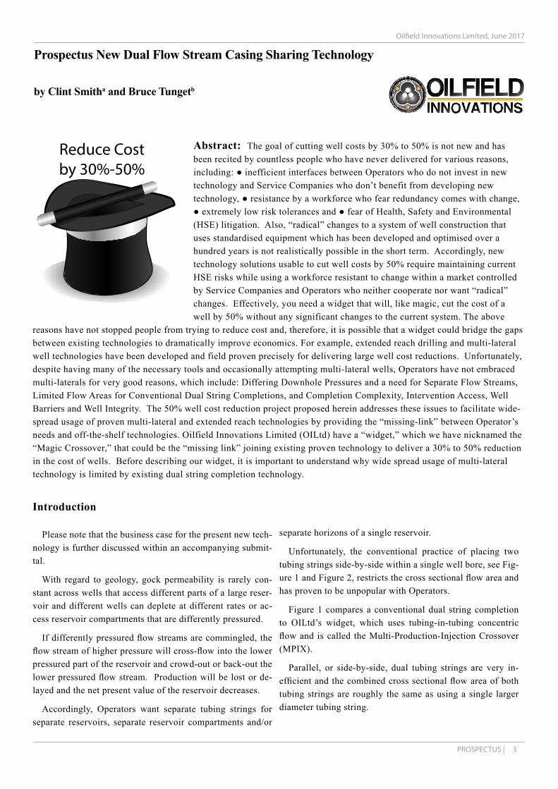
Figure 1 - Comparison of MPIX to Conveniontal Dual String Completions
Conventional Parallel String Completions
Figure 1 shows that a 9 5/8” casing can accommodate two 3 ½” tubing strings, each with 7.03 in2 flow area, for a com-bined flow area of 14.03 in2, which is comparable to a single 4 ½” tubing string flow area of 12.3 in2 and significantly less than a 5 ½” (17-ppf) tubing string cross sectional flow area of 18.8 in2, which could have been used instead of the two 3 ½” tubing strings.
Practically speaking, a conventional dual tubing string completion provides ½ of the flow area for one lateral and ½ the flow area for another lateral and, therefore, ½ well + ½ well = 1 well with no cost savings
Figure 1 also shows that a 7 5/8” outer tubing string can be installed within the 9 5/8” casing and a 4 ½” inner tubing string can be installed therein to provide a combined flow
area of 30.9 in2, which is roughly equal to a combination of two production strings (4 ½” and 5 ½”).
Accordingly, Oilfield Innovations’ MPIX technology can deliver the flow area of 1 well + 1 well = 2 wells through a single 9 5/8” casing.
Other tubing combinations are also possible. For example, 2 3/8” inner tubing within 5 ½” outer tubing and 2 7/8 or 3 ½” inner tubing within 6 5/8” outer tubing can be used.
A primary reason for the conventional practice of using parallel dual tubing strings is installation of surface con-trolled tubing retrievable subsurface safety valves, as shown in Figure 2.
Because the diameter of safety valves are too large to in-stall side-by-side, two small diameter tubing valves must be used and spaced out to fit them within the casing.
5
Terms of Reference
July 2017 - PROSPECTUS |
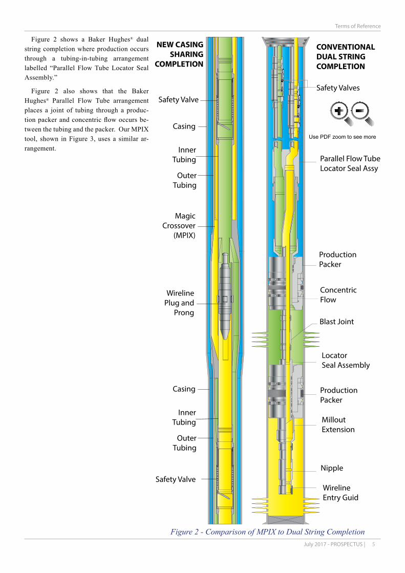
Figure 2 - Comparison of MPIX to Dual String Completion
Figure 2 shows a Baker Hughes® dual string completion where production occurs through a tubing-in-tubing arrangement labelled “Parallel Flow Tube Locator Seal Assembly.”
Figure 2 also shows that the Baker Hughes® Parallel Flow Tube arrangement places a joint of tubing through a produc-tion packer and concentric flow occurs be-tween the tubing and the packer. Our MPIX tool, shown in Figure 3, uses a similar ar-rangement.
Safety Valves
CONVENTIONALDUAL STRINGCOMPLETION
Parallel Flow TubeLocator Seal Assy
ProductionPacker
ConcentricFlow
Blast Joint
LocatorSeal Assembly
ProductionPacker
MilloutExtension
Nipple
WirelineEntry Guid
Safety Valve
Casing
InnerTubing
OuterTubing
Safety Valve
MagicCrossover
(MPIX)
WirelinePlug and
Prong
NEW CASINGSHARING
COMPLETION
Casing
InnerTubing
OuterTubing
Use PDF zoom to see more
6 |www.oilfieldinnovations.com
New Casing Sharing Technology
PLU
G
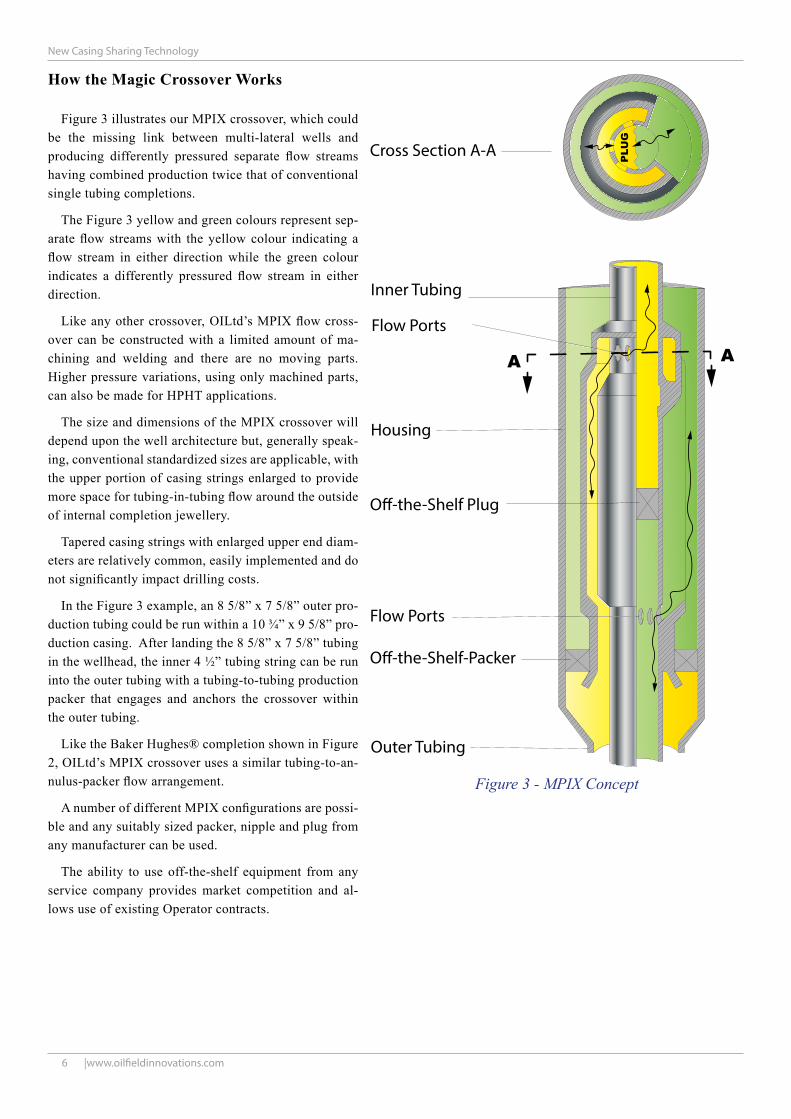
Inner Tubing
Cross Section A-A
Outer Tubing
Flow Ports
Flow Ports
Housing
O�-the-Shelf Plug
O�-the-Shelf-Packer
A A
How the Magic Crossover Works
Figure 3 illustrates our MPIX crossover, which could be the missing link between multi-lateral wells and producing differently pressured separate flow streams having combined production twice that of conventional single tubing completions.
The Figure 3 yellow and green colours represent sep-arate flow streams with the yellow colour indicating a flow stream in either direction while the green colour indicates a differently pressured flow stream in either direction.
Like any other crossover, OILtd’s MPIX flow cross-over can be constructed with a limited amount of ma-chining and welding and there are no moving parts. Higher pressure variations, using only machined parts, can also be made for HPHT applications.
The size and dimensions of the MPIX crossover will depend upon the well architecture but, generally speak-ing, conventional standardized sizes are applicable, with the upper portion of casing strings enlarged to provide more space for tubing-in-tubing flow around the outside of internal completion jewellery.
Tapered casing strings with enlarged upper end diam-eters are relatively common, easily implemented and do not significantly impact drilling costs.
In the Figure 3 example, an 8 5/8” x 7 5/8” outer pro-duction tubing could be run within a 10 ¾” x 9 5/8” pro-duction casing. After landing the 8 5/8” x 7 5/8” tubing in the wellhead, the inner 4 ½” tubing string can be run into the outer tubing with a tubing-to-tubing production packer that engages and anchors the crossover within the outer tubing.
Like the Baker Hughes® completion shown in Figure 2, OILtd’s MPIX crossover uses a similar tubing-to-an-nulus-packer flow arrangement.
A number of different MPIX configurations are possi-ble and any suitably sized packer, nipple and plug from any manufacturer can be used.
The ability to use off-the-shelf equipment from any service company provides market competition and al-lows use of existing Operator contracts.
Figure 3 - MPIX Concept

7June 2017 - PROSPECTUS |
New Casing Sharing Technology
A B C
MMV
HMV
SV
PWVKV
WELLHEADANNULUSVALVE
SAFETYVALVE
COMPLETIONTUBING STRING &COMPONENTS
PRODUCTIONPACKER
CASING &CEMENT
IN-SITUFORMATION
IN-SITUFORMATION
CASING &CEMENT
PROD.CASING
CASINGHANGER& SEALS
WELLHEAD
TREE& VALVES
Well Barriers
About this point the listener or reader typically acknowl-edges the benefits of concentric flow and using off-the-shelf equipment then asks… “why cross the flow streams between the inner tubing and annulus? Why not just flow through the annulus and tubing without crossing over?”
It is a good question and the answer is “producing oil and gas through the annulus is a conventionally unacceptable Health Safety and Environmental risk.”
As shown in Figure 4, conventional practice uses at least two (2) well control barriers.
Primary well control barriers are shown in blue and com-prise the tubing and valves that close across production.
Secondary barriers are shown in red and comprise the ce-ment, casing, wellhead, production tree and valves associated with the annulus.
Conventional practice reserves the use of the intermediate tubing-casing-annulus for pressure monitored leak detection.
Changes in annulus pressure can indicate that the primary barrier has failed. When the primary barrier leaks, the sec-ondary barrier protects people and the environment from hy-drocarbon pollution, ignition and/or explosion and produc-tion is stopped until the primary barrier is fixed.
Primary and secondary well control barriers are regulato-ry and legal liability requirements and, therefore, production through an annulus is not conventionally acceptable.
Injection (not production) of gas into an annulus to facilitate or enhance production through the tubing is often confused with flowing through an annulus. Injecting small amounts of hydrocarbon gas into the annulus can be stopped at surface, wherein the injected gas volume is small and quickly deplet-ed. Many Operators also install a one way annulus safety valve that allows gas injection but prevents discharge of hy-drocarbons from the annulus.
As a matter of fact, tubing safety valves are fail-safe-close “production” valves while annular safety valves are fail-safe-close “injection” valves used, for example, with gas lift injec-tion to prevent production through the annulus. Tubing and annulus safety valves “fail-safe” in opposite flow directions.
Figure 4 - Conventional Barriers

8 |www.oilfieldinnovations.com
New Casing Sharing Technology
Well #1 Production or Injection
TubingHangers
Well #2 Production or Injection
Well #1 Safety Valve
Well #2 Safety Valve
InterventionSliding Valve
InterventionWireline Plug
MPIX - Multi-Production or Injection Crossover
MPIX Packer
Production Packer(e.g. 9 5/8”)
Intermediate Casing(e.g. 14” x 13 3/8”)
Production Casing(e.g. 10 3/4” x 9 5/8”)
Production Annulus
Well #1 - Inner Tubing(e.g. 4 1/2”)
Well #2 - Tubing (e.g. 8 5/8”x7 5/8”)
Use PDF zoom to see more
Simply Intelligent Completion
Production through an annulus is not conven-tionally acceptable and conventional “intelligent completions” are very complex.
Our MPIX widget uses tubing-in-tubing flow crossover to preserve the tubing-to-casing annu-lus for pressure monitoring and leak detection as well as preserving conventional primary and sec-ondary well barriers.
Crossing over flow streams allows intelligent and independent control of each flow stream us-ing conventional downhole equipment designed to affect the tubing bore.
By crossing flow streams, conventional down-hole equipment can affect the tubing bore of one flow stream “after it flows through the cross-over” while independently affecting the other flow stream “before it flows through the cross-over.” Accordingly, two flow streams can be inde-pendently controlled at different points along “the same tubing bore.”
A safety valve above the crossover controls one flow stream while a safety valve below the cross-over controls the other.
Accordingly, like magic, Figure 5 shows how conventional valves, gauges, chemical injection and other tubing bore specific equipment can af-fect or measure both flow streams independently and simultaneously.
A tertiary reason for crossover flow comprises using a removable wireline plug for through-tub-ing access to the bottom of the well during inter-vention operations.
A sliding valve within the crossover can be used to stop cross flow between differently pressured concentric tubing strings when the intervention wireline plug is removed during, for example, downhole production logging operations.
Figure 5 - MPIX in Practice

9June 2017 - PROSPECTUS |
New Casing Sharing Technology
A B C
MMVMMVHMVHMV
SV
PWVPWV
KV
KV
WELLHEADANNULUSVALVE
SAFETYVALVE
MPIXCROSS-OVER
SAFETYVALVE
COMPLETIONTUBING STRING &COMPONENTS
PRODUCTIONPACKER
CASING &CEMENT IN-SITU
FORMATION
IN-SITUFORMATION
CASING &CEMENT
PROD.CASING
CASINGHANGER& SEALS
WELLHEAD
TREE& VALVES
Conventional Barriers
Multi-bore trees and tubing hangers suitable for the Baker Hughes® example of Figure 2 can be used or conductor shar-ing arrangements (discussed in an accompanying submittal) can be used for surface or subsea MPIX flow crossover ar-rangements.
As shown in red and blue in Figure 6, a conventional multi-bore production tree together with the wellhead and casing form the traditional secondary well barrier elements while the traditional production packer, outer tubing string and safety valves attached to the MPIX crossover form the primary barri-ers.
The tubing-to-tubing packer and wireline plug within the MPIX crossover separate the two flow streams and, thus, are not environmental barriers.
Accordingly, a completion using the MPIX crossover is compliant with industry best practice and regulatory require-ments as shown by the blue primary and red secondary barrier lines in the Figure 6 NORSOK diagram.
Figure 6 also depicts the MPIX crossover within a well that separates lower pressured production from deeper higher pres-sure production using an intermediate production packer with-in a single well bore.
While many applications of vertically separated differently pressured reservoirs exist, multi-lateral, extended reach and horizontal drilling technology can also provide the opportunity to access different fault blocks and/or large and diverse areas of a reservoir.
Brownfield redevelopment of depleted reservoirs and small pools or marginal greenfield hydrocarbon reservoirs can be-come more economic if they can be accessed from a single well or a smaller number of wells that can produce differently pressured flow streams through the same well bore.
Figure 6 - MPIX Barriers

10 |www.oilfieldinnovations.com
New Casing Sharing Technology
Well #1 - Production or InjectionWell #2 - Production or Injection
Well #1 Flapper Safety Valve
Well #2 Flapper Safety Valve
Intervention Sliding Valve
Intervention Wireline Plug
MPIX - Multi-Production-InjectionCrossover
Conventional Packer
Production Packer(e.g. 9 5/8”)
Tapered Intermediate Casing(e.g. 14” x 13 3/8”)
Tapered Production Casing(e.g. 10 3/4” x 9 5/8”)
Selective Re-Entry Tool
Well #1 Wireline Plug
Well # 2 Nipple
Perforated Joint
Liner Hanger Packers
Liner Hangers
Production Packers
Level 6 Multi-Lateral Expandable Junction (e.g. 9 5/8”)
Well #1 - Inner Tubing (e.g. 4 1/2”)
Well #2 - Tubing (e.g. 8 5/8”x7 5/8”)
Production Liners (e.g. 7”)
Production Tubing (e.g. 4 1/2”)
Well #1Lower Completion Well #2 Lower Completion
Use PDF zoom to see more
Multi-Laterals
Figure 8 depicts example geology for the Figure 7 illustration of a level 6 multilateral junction used to provide two independent well bores that can access differently pressured or depleted portions of a reser-voir and be produced separately using the MPIX tool.
The upper part of Figure 7 corresponds to the MPIX tool of Figure 5 with the addition of a Baker Hughes® Selective Re-Entry Tool to allow through tubing bot-tom hole access to each branch of the multilateral.
As shown in Figure 8, multilateral technology and directional drilling have advanced to a level that al-lows the multilateral branch’s bottom hole location to be many kilometres apart to truly provide multiple wells accessing different parts, compartments or fault blocks of a reservoir from a single surface or subsea well bore.
Obviously, from the multi-lateral junction, drill-ing each branch incurs the same costs as if they were drilled from different wells, but other savings can off-set these costs.
For example, rig moves or skidding between well slots is not necessary. Also, the same bottom hole as-semblies can apply to both laterals and learnings from one lateral can be immediately applied to the other.
Conventional vertical subsea trees, or dual bore surface production trees, used for side-by-side tubing completions can be adapted for use, wherein a cost reduction in subsea infrastructure or topside facilities can be realised with smaller space requirements and fewer production slots, wherein reductions subsea in-frastructure like pipelines, manifolds and umbilical can be realised.
Lighter topsides or fewer subsea production trees and tie-backs with small footprints, shorter jumper hoses, umbilical lines and pipelines are all cost sav-ings associated with placing two wells within a single conductor with a single production tree.
Figure 7- MPIX Multi-Lateral
11June 2017 - PROSPECTUS |
New Casing Sharing Technology
7 -in. linerabove reservoir
Rig overConventionalPlatform or Subsea Well
5/8 5-in. lineror sand-screencompletion
Fault
16-in. casing
Shallow Gas
at shallow depth
133/8-in. or 14-in. casing at intermediate depth
9 5/8 or Multi-Lateral Level 6 Junction Casing Shoe10 3/4
Shallow Gas
3,000-ft900-m
6,000-ft1,800-m
9,000-ft2,700-m
12,000-ft3,600-m
7 -in. linerabove reservoir
5/8
5-in. lineror sand-screencompletion
7,500-ft2,300-m
7,500-ft2,300-m
ft.
True vertical depth, m
1,525
0
3,050
4,575
6,100
m.1,5250 3,050 4,575 6,100 7,620 9,150 10,670 12,020
True
ver
tical
dep
th, f
t
Horizontal departure
7,500-ft (2,300m) Horizontal Departurewith 3,000ft (900m) Vertical Depth
0
5,000
10,000
15,000
20,00040,00035,00030,00025,00020,00015,00010,0000 5,000
Low reachMedium reachExtended reachUltraextended reachERD well
4.03.0
2.0
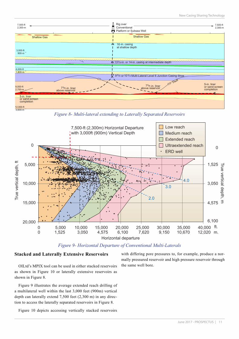
Figure 9- Horizontal Departure of Conventional Multi-Laterals
Figure 8- Multi-lateral extending to Laterally Separated Reservoirs
Stacked and Laterally Extensive Reservoirs
OILtd’s MPIX tool can be used in either stacked reservoirs as shown in Figure 10 or laterally extensive reservoirs as shown in Figure 8.
Figure 9 illustrates the average extended reach drilling of a multilateral well within the last 3,000 feet (900m) vertical depth can laterally extend 7,500 feet (2,300 m) in any direc-tion to access the laterally separated reservoirs in Figure 8.
Figure 10 depicts accessing vertically stacked reservoirs
with differing pore pressures to, for example, produce a nor-mally pressured reservoir and high pressure reservoir through the same well bore.

12 |www.oilfieldinnovations.com
New Casing Sharing Technology
MD (RTE)
MD (RTE)
0
LITHOLOGY
SHALE
SHALE
CAP ROCK
A1 SAND
CHALK
SALT
CAP ROCK
J1-SAND
J1-SAND
EOCENETO
RECENT
PALAEOCENE
TRIASSIC
CRETACEOUS
30" CONDUCTOR
20" SURFACE CASING
13 3/8" INTERMEDIATE CASING
9 5/8" PRODUCTION CASING
7 5/8" PROD.
TUBINGTIE-BACK
7 5/8” X 9 5/8”PRODUCTION
ANNULUS
7" PRODUCTION LINER
PERF-4
PERF-2
PERF-1
PERF-5
PERF-6
PERF-7
PERF-8
PERF-9
7 5/8" EXTERNALPRODUCTIONTUBING TIED-BACK
4 1/2" INTERNALPRODUCTIONTUBING
UPPER PRODUCTIONOR INJECTIONZONE
LOWER PRODUCTION OR INJECTION ZONE
MULTI-PRODUCTIONAND/OR INJECTIONCROSSVER
UPPER PROD / INJECT
LOWER PROD / INJECTCONVENTIONALA, B & C ANNULI
LOWER PRODUCTION OR INJECTION ZONE
9000
10000
11000
13000
12000
15000
16000
14000
15000
16000
14000
13000
12000
11000
10000
9000
1000
2000
3000
4000
5000
6000
7000
80008000
7000
6000
5000
4000
3000
2000
1000
PRODUCTIONPACKER
PRODUCTONPACKER
Figure 10- MPIX Single Bore Completion in Vertically Stacked Reservoir

13June 2017 - PROSPECTUS |
New Casing Sharing Technology
Figure 11- Single Subsea Well Tie-Back
Technology Readiness Level
With the exception of our MPIX flow crossover, all API 17N Technology Readiness Level 7 (TRL-7) field proven equipment can be used to deliver two-wells-for-the-price-of-one and a 50% well cost reduction.
The MPIX development stages using the API 17N technol-ogy readiness level scheme are envisaged to comprise:
TRL 0: This proposal and any subsequent work with the Investor necessary to get the project started.
TRL 1: Identification of Operator(s) and Service Compa-ny(s) interested in the technology. Selection of the casing and tubing sizes appropriate for the North Sea and development of 3d models, machining drawings and strength analysis. Fi-nite Element Analysis (FEA) of the theoretical specifications for the specified size of MPIX crossover within various com-pletion configurations.
TRL 2: Provision of the TRL 1 drawings to the identified Service Company(s) who can validate the design against their completion, wellhead and surface tree equipment. Provision of the drawings and calculations to a qualified Design Review Company for verification. Revision of the machining and welding drawings according to the Service Company(s) and the Design Review Company’s feedback with recalculation and re-validation of the theoretical specifications according
to the revised drawings.
TRL 3: Based on TRL 2 results, construction and qualifi-cation testing of the prototype crossover in an above ground simulated environment with two simultaneous flow streams pumped through the crossover while being subjected to bend-ing forces and measurements taken by strain gauges for vi-bration and fatigue analysis.
TRL 4: Based upon the TRL 3 results, construction of the MPIX by a qualified and committed Service Company(s) for use with their completion, wellhead and production tree equipment, whereby the company makes any necessary ad-aptations of the MPIX and their existing designs to accom-modate integration of the flow crossover. Said Service Com-pany(s) provide the existing, adapted and/or new equipment for stack-up qualification testing of the MPIX tool within a surface test bay and/or test well.
TRL 5: Qualification testing of the crossover within a test well, wherein retrievable packers are used to simulate the in-stallation sequence of the crossover, safety valves and control lines within a wellhead using the intended tubing hangers and a suitable surface tree. After installation, pressure and flow testing are carried out by flow through the completion with strain gauge and vibration collecting data for analysis using different flow rates over an extended period of time.
TRL 6 & TRL 7: The results of TRL-4 and TRL 5 are pre-

14 |www.oilfieldinnovations.com
New Casing Sharing Technology
sented to Operators and incorporated into a well design, the equipment is manufactured and installed within the field. Over a period of time both surface and subsea well installa-tions are performed until the technology is proven and inte-grated into the existing set of industry equipment.
With regard to the accompanying submittals for conductor sharing and large diameter high pressure conducts, Oilfield Innovations’ “Magic Crossover” is likely to be the simplest innovation to start with. A development plan can be relative-ly straight forward and simple with the benefits of minimal changes to conventional well integrity and two-wells-for-the-price-of-one, but the following market barriers must be tra-versed:
• Operator Supply Chain’s will not accept small compa-ny liabilities while Well Operations Professionals receive no benefits from using new technology and, thus, are nat-urally risk adverse,
• Large Service Companies rarely participation in or purchase new technologies until they are competitive or receive up-front payments, and
• OILtd lacks the credibility to promote the technology and cannot afford cash funding through TRL 6.
Accordingly, Oilfield Innovations proposes traversing the market barriers-to-entry by starting with a project encom-passing TRL 1 and TRL 2 development, wherein:
• TRL 0 - Investor and OILtd agree a plan for develop-ing the technology and Investor agrees to use its industry
connections to survey interest in the technology,
• TRL 1 to TRL 2 – Investor uses its Operators and Ser-vice Company interfaces to survey interest in the MPIX crossover. OILtd’s in-kind 50% contribution can com-prise creation of a 3D computer model with machining and welding drawings for the mutually agreed tubing sizes with a Finite Element Analysis (FEA) of the MPIX crossover. Investors 50% contribution comprises paying a qualified design company to verify, propose revisions and validate OILtd’s drawings, calculations and 3D com-puter model. The resulting qualified report verifying the practicality of the MPIX crossover would them be pro-vided to Operators and Service Companies. A Scottish or United Kingdom University could also be included within the work.
• TRL 3 to TRL 7 will depend upon the TRL 2 results, which can be used to start a Joint Industry Project (JIP) of Operator(s) wanting to use the technology and Service Company(s) wanting to construct and/or use the MPIX Crossover with their TRL-7 equipment. As descried in the accompanying submittals Oilfield Innovations pat-ents could also be open sourced in a plug-and-play supply chain arrangement.
The estimated cost for development through TRL 2 is, more or less, between £50,000 and £100,000, depending upon the Design Verification Company selected. Oilfield Innovations’ contribution would comprise providing an FEA analysis and 3D computer model with machining and welding drawings
Figure 12- Multi-Lateral
15June 2017 - PROSPECTUS |
New Casing Sharing Technology
Conclusion
In summary, the proposed crossover has no moving parts and can be machined and/or welded easily, whereby the re-sulting mechanism can be used to link TRL 7 technologies to deliver two wells for the price of one.
Tubing-in-tubing flow has been used for many years in the solution mining industry where the arrangement is used over approximately a two year period to dissolve salt and create huge underground storage caverns. Given this usage and availability of data, tubing-in-tubing flow may be between TRL 4 and TRL 6, wherein the probability of successfully implementing oil and gas tubing-in-tubing production and/or injection is very high.
Comparing the cost of the drilling two wells to the cost of drilling an MPIX well, qualification costs through TRL 6
could be recovered within the first application.
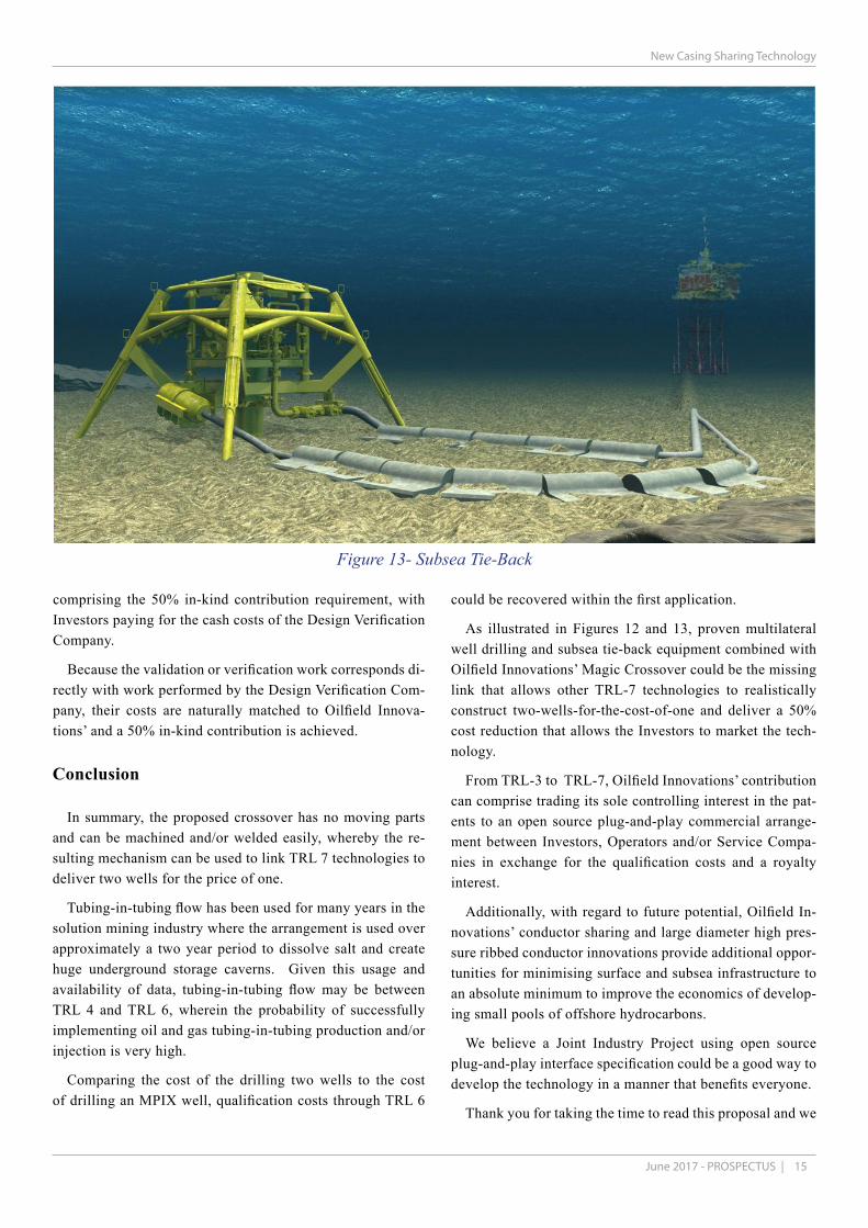
As illustrated in Figures 12 and 13, proven multilateral well drilling and subsea tie-back equipment combined with Oilfield Innovations’ Magic Crossover could be the missing link that allows other TRL-7 technologies to realistically construct two-wells-for-the-cost-of-one and deliver a 50% cost reduction that allows the Investors to market the tech-nology.
From TRL-3 to TRL-7, Oilfield Innovations’ contribution can comprise trading its sole controlling interest in the pat-ents to an open source plug-and-play commercial arrange-ment between Investors, Operators and/or Service Compa-nies in exchange for the qualification costs and a royalty interest.
Additionally, with regard to future potential, Oilfield In-novations’ conductor sharing and large diameter high pres-sure ribbed conductor innovations provide additional oppor-tunities for minimising surface and subsea infrastructure to an absolute minimum to improve the economics of develop-ing small pools of offshore hydrocarbons.
We believe a Joint Industry Project using open source plug-and-play interface specification could be a good way to develop the technology in a manner that benefits everyone.
Thank you for taking the time to read this proposal and we
Figure 13- Subsea Tie-Back
comprising the 50% in-kind contribution requirement, with Investors paying for the cash costs of the Design Verification Company.
Because the validation or verification work corresponds di-rectly with work performed by the Design Verification Com-pany, their costs are naturally matched to Oilfield Innova-tions’ and a 50% in-kind contribution is achieved.

16 |www.oilfieldinnovations.com
New Casing Sharing Technology
Further Information
Addition detailed information on the Oilfield Innovations’ Multiple Injection Production Crossover (MPIX) Technolo-gy, described above, can be found in the accompanying sub-mittal of Oilfield Innovations’ Conductor Sharing Technolo-gy. Please provide this document to your engineers and we would be happy to answer any further queries. For additional information or further queries please contact Clint Smith or Bruce Tunget at the below email addresses.
Notes and referencesa Clint Smith is Professional Engineer in the State of Texas, began working in the Drilling, Intervention and Well Operations in 1978 and lives in Houston, Texas, USA; Curriculum Vitae (CV) available upon request; [email protected]
b Bruce Tunget earned a PhD. and MSc in Mineral Economics and a BSc in Mineral Engineering from the Colorado School of Mines, is a Chartered Financial Analyst, began working in Drilling, Intervention and Abandonment Operations in 1982 and lives in Aberdeen, Scotland; Curriculum Vitae (CV) available upon request; [email protected]
† Various photograph have been taken from the following cited references.
‡ Footnotes: See accompanying Conductor Sharing Technology submittal for References.
This document is copyrighted by Oilfield Innovations and may be free distribut-ed but not altered without written consent.
hope it meets your requirements.