Embed Size (px)
Citation preview

PROSTHETIC PROCEDURES

2
INDEX
Catalog presentation .............................................................3
CONNECTION CONEXA .....................................................4
- Unique prosthetic connection ..........................................4
- Unlocking system ..............................................................5
PROSTHETIC KIT ...................................................................5
PROSTHETIC OPTIONS ........................................................6
HEALING COMPONENTS .....................................................7
IMPRESSION COMPONENTS...............................................8
PULL-OFF TRANSFER ............................................................9
FACILITY TRANSFER ............................................................10
PICK-UP TRANSFER .............................................................11
TEMPORARY ABUTMENT - PEEK .......................................12
TEMPORARY ABUTMENT - TITANIUM ..............................14
TRY-INN ABUTMENT ...........................................................16
CEMENTED-RETAINED RESTORATION ............................17
TITANIUM ABUTMENT ........................................................18
CASTABLE ABUTMENT – PLEXIGLASS ..............................20
- Investment ......................................................................22
MULTI-SCAN ABUTMENT ...................................................23
- Traditional method .........................................................24
- With cad/cam .................................................................25
MULTI-USE ABUTMENT .......................................................26
BRIDGE ..................................................................................28
- Impression taking .........................................................28
- Temporary prosthesis ....................................................29
- Definitive prosthesis ......................................................30
EQUATOR SYSTEM ..............................................................32
EQUATOR .............................................................................33
SPHERICAL ANCHOR SYSTEM ..........................................34
O-BALL ABUTMENT ............................................................35
BAR SYSTEM .........................................................................37
- Impression taking .........................................................38
- Definitive prosthesis ......................................................39
3
implant companyB&B DENTAL
Welcome to this updated edition of DURAVIT prosthetic procedure manual.
B. & B. Dental S.r.l. is an Italian leading company in biomedical field specialized in the development of dental implants and materials for bone regeneration. The experience gained over the years has helped to provide high quality prosthetic implant technologies and innovative materials with affordable prices.Products and techniques are constantly improved, developed and innovated, paying attention to customer satisfaction and to meet customer needs. This is the main goal that B. & B. Dental aims to achieve.
B. & B. Dental produces and markets:- B&B DENTAL SYSTEM: dental implant system.- B&B DENTAL GUIDED SURGERY SYSTEM: guided surgery system.- B&B DENTAL CRESTAL SINUS LIFT: system used for the sinus lift.- NOVOCOR PLUS and materials for bone regeneration.- T-BARRIER TITANIUM MEMBRANES.- T-BARRIER COLLAGEN MEMBRANES.
B. & B. Dental promotes also training courses especially for dentists and dental technicians, during which implant-prosthetic techniques are taught step by step. Knowledge about the specific use of the individual components of the DURAVIT system are provided, as the opportunity to experience directly the wide range of the offered prosthetic solutions.
CATALOG PRESENTATION
The awareness that the realization of a proper prosthesis on implant is a critical step for their long-term life time, has motivated the writing of this demonstrative catalog dedicated to dental technicians.
The catalog describes in details all the prosthetic components of the DURAVIT system and their use. Especially it is designed for being used by clinicians, who have undergone at least basic surgical and in-clinic implant training. All the information have specific illustrations in order to guide professionals through the wide range of options for the impression taking and the following built of the definitive prosthesis. Therefore it explains the essential steps regarding implant planning, surgical and prosthetic procedures.
B. & B. Dental has an interest to keep up-dated each doctor over the latest trends and treatment techniques about implants in order to provide the most simple implant solution even in case of complex cases.

4
CONEXATHE REVOLUTIONARY CONNECTION
PLATFORM SWITCHING
Reduction of bone loss.
Long term esthetic stability.
Perfect bacterial seal.
INTERNAL HEXAGON
The hexagon enhances the resistance to torsional loads and allows an easy transfer of the abutment position from the laboratory to the dental office.
CONICAL CONNECTION“MORSE TAPER 5°“
Cold weld seal.
Elimination of micro-movements.
Elimination of unscrewing.
PROSTHETIC SCREW
The only function is to bring in total connection the abutment and the implant.
It is not subjected to loads, eliminating the risk of breakage.
UNIQUE PROSTHETIC CONNECTIONThanks to the unique prosthetic connection (hole diameter 3 mm), the range is compatible with all prosthetic implants 3P, EV and WIDE, regardless of the stump or pillar chosen and the diameter of the implant.
3P LINE EV LINE WIDE LINE

5
1 2
3 4
Unscrew the prosthetic. Insert the extractor screw inside theabutment by using thehexagonal driver.
Screw clockwise theextractor screw untilthe abutment comesout.
PROSTHETIC KIT Ref. KITPROTESICO
UNLOCKING SYSTEM The morse taper is created by the friction between two conical surfaces (implant and abutment), that combined with the push and pressure applied in the insertion, locks them. The locking can be deleted only using an extractor screw “EXTRACTOR” (Ref. INN-6060).
Once the abutmentcomes out unscrew the extractor.
MANUAL DRIVERS Ref. INN-00604
TORQUERATCHET
Ref. 00376DIN
PROSTHETIC SCREW DRIVERRef. INN-61000 (short)Ref. INN-61000L (long)
EXTRACTORRef. INN-6060
SPHERICAL SCREW DRIVERSRef. INN-00637
6
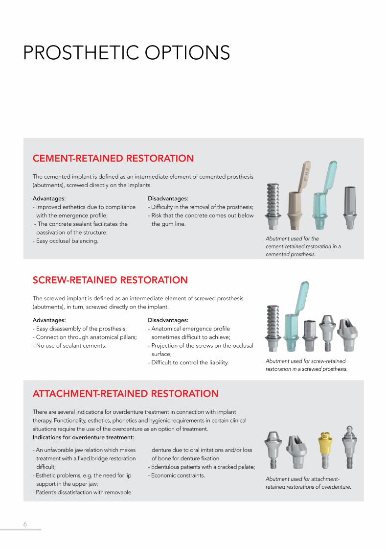
PROSTHETIC OPTIONS
CEMENT-RETAINED RESTORATIONThe cemented implant is defined as an intermediate element of cemented prosthesis (abutments), screwed directly on the implants.
SCREW-RETAINED RESTORATIONThe screwed implant is defined as an intermediate element of screwed prosthesis (abutments), in turn, screwed directly on the implant.
Abutment used for the cement-retained restoration in a cemented prosthesis.
Abutment used for screw-retained restoration in a screwed prosthesis.
Abutment used for attachment-retained restorations of overdenture.
Advantages:- Improved esthetics due to compliance
with the emergence profile; - The concrete sealant facilitates the
passivation of the structure;- Easy occlusal balancing.
Disadvantages:- Difficulty in the removal of the prosthesis;- Risk that the concrete comes out below
the gum line.
Advantages:- Easy disassembly of the prosthesis;- Connection through anatomical pillars;- No use of sealant cements.
Disadvantages:- Anatomical emergence profile
sometimes difficult to achieve;- Projection of the screws on the occlusal
surface;- Difficult to control the liability.
ATTACHMENT-RETAINED RESTORATIONThere are several indications for overdenture treatment in connection with implanttherapy. Functionality, esthetics, phonetics and hygienic requirements in certain clinicalsituations require the use of the overdenture as an option of treatment.Indications for overdenture treatment:
- An unfavorable jaw relation which makes treatment with a fixed bridge restoration difficult;
- Esthetic problems, e.g. the need for lip support in the upper jaw;
- Patient’s dissatisfaction with removable
denture due to oral irritations and/or loss of bone for denture fixation
- Edentulous patients with a cracked palate;- Economic constraints.

7
ø 5ø 5
ø 5ø 5
H. 1 H. 2
ø 5
H. 3H. 5
H. 7
Ref. INN-6010 Ref. INN-6011 Ref. INN-6012 Ref. INN-6014 Ref. INN-6015
ø 6ø 6
ø 6ø 6 ø 6
INN-6020 INN-6021 INN-6022 INN-6023 INN-6024
H. 1 H. 2H. 3 H. 5
H. 7
INN-6053 INN-6053/1 INN-6053/2 INN-6053/3
H. 1 H. 2 H. 3
TIGHTENING: Insert the healing screw into the implant and tighten with only light finger force.
HEALING COMPONENTS
COVER SCREWIt is provided in the implant package. Use it when you want to cover completely the implant after its insertion.The implant will be reopened 3-6 months later, followed by the use of healing screw.
HEALING SCREWS Ø5INDICATED FOR ANTERIOR AREAThese components are used to rehabilitate soft tissue on the implant in order to insert the final prosthetic abutment later on.
HEALING SCREWS Ø6INDICATED FOR POSTERIOR AREAThese components are used to rehabilitate soft tissue on the implant in order to insert the final prosthetic abutment later on.
Surgical procedures Laboratory procedures

8
IMPRESSION COMPONENTS
PULL-OFF TRANSFER(CLOSED TRAY TECHNIQUE)
Made of plastic and single-use only. It provides an impression taking that is easy and fast for each patient.
Each package contains 3 pieces. Ref. INN-00306
The transfer has to be combined with the analog.Ref. INN-00585
TRANSFER FACILITY(CLOSED TRAY TECHNIQUE)
t is packaged in 3 pieces. It ensures optimal fit and precise impression taking in cases of large disparallelism.
Each package contains: 1 plastic cap, 1 screw and 1 metal transfer.
Each package of plastic cap contains 2 pieces.
The transfer has to be combined with the analog INN-00585,as shown above.
PICK-UP TRANSFER(OPEN TRAY TECHNIQUE)The pick-up transfers ensures an optimal fit and a precise impression taking for each patient.
The package contains: 1 pick-up transfer and 1 short pick-up screw.It is available even the long pick-up screw.
The transfer has to be combined with the analog INN-00585, as shown above.
TRANSFER SCREW(Long)
INN-00608L
ANALOG INN-00585
PULL-OFFTRANSFERINN-00306
PLASTIC CAP
INN-00507
METALTRANSFER
(Long) INN-00506L
METALTRANSFER
(Short) INN-00506
COMPLETE SET- post screw
- hexagonal open tray transferINN-00600
COMPLETE SET- post screw
- rotating open tray transferINN-00601

9
1 2
3 4
5 6
87
PULL-OFF IMPRESSION TRANSFERCLOSE TRAY TECHNIQUE
Clean the internal connection of the implant throughly from blood, tissue, etc. prior to the impression procedure.
Position the transfer in the analog and push until you feel the tactile response of engagement.
Make little lateralmovements to verify thecorrect insertion of thetransfer.
Take the impression using an elastomeric impression material (polyvinyl siloxane or polyether rubber).
Note: Due to its low tensile strength, hydrocolloid is not suitable for this application.
Position the analog in the tray and smoothly push until you feel the tactile response of engagement.
Once the material is cured, carefully remove the tray.
The transfer remains in the impression materialautomatically when it is pulled off from the tray.
Fabricate the mastercast using standardmethods and type 4 dental stone (DIN 6873).
A gingival mask shouldalways be used to ensure that the emergence profile ofthe crown is optimally contoured.
Surgical procedures Laboratory procedures
10
1 2
4
5 6
7 8
3
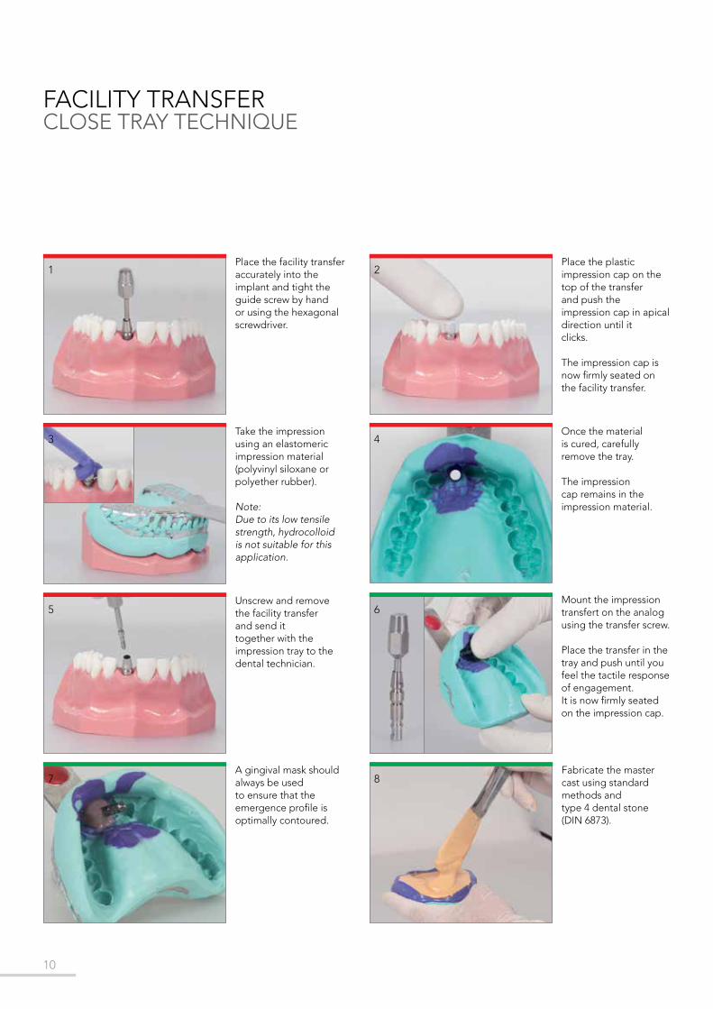
FACILITY TRANSFERCLOSE TRAY TECHNIQUE
Place the facility transfer accurately into theimplant and tight the guide screw by hand or using the hexagonal screwdriver.
Place the plasticimpression cap on the top of the transferand push the impression cap in apical direction until itclicks.
The impression cap is now firmly seated on the facility transfer.
Take the impressionusing an elastomericimpression material (polyvinyl siloxane or polyether rubber).
Note: Due to its low tensile strength, hydrocolloid is not suitable for this application.
Once the materialis cured, carefullyremove the tray.
The impression cap remains in the impression material.
Mount the impression transfert on the analog using the transfer screw.
Place the transfer in the tray and push until you feel the tactile response of engagement. It is now firmly seated on the impression cap.
Unscrew and removethe facility transferand send ittogether with theimpression tray to thedental technician.
A gingival mask shouldalways be used to ensure that the emergence profile is optimally contoured.
Fabricate the mastercast using standardmethods and type 4 dental stone(DIN 6873).

11
A
1 2
3 4
5 6
B
87
FACILITY TRANSFERCLOSE TRAY TECHNIQUE
PICK-UP TRANSFER OPEN TRAY TECHNIQUE
Clean the internal connection of the implant thoroughly from blood, tissue, etc. prior to the impression procedure.
Place the pick-up transfer accurately intothe implant and by hand (Fig. A) or usingthe hexagonal screwdriver tight the pick-up screw.
Make perforations in the custom-made impression tray
Take the impressionusing an elastomericimpression material (polyvinyl siloxane or polyether rubber).
Uncover the screws before the material is cured.
Once the material iscured, loosen the pick-up screws andremove the tray.
A gingival mask shouldalways be used to ensure that the emergence profile ofthe crown is optimally contoured.Fabricate the mastercast using standardmethods and type 4 dental stone(DIN 6873).
Reposition and fix the analog in the impressionusing the guide screw.To avoid inaccuracies when connecting, theanalog must be posi-tioned exactly in line with the grooves of the analog before screw-ing in.
7
The pick-up transferremains automaticallyin the impressionmaterial.
Surgical procedures Laboratory procedures

12
H. 1 H. 2 H. 3
ø 5 ø 5 ø 5
H. 1 H. 2 H. 3
ø 5 ø 5ø 5
FV107.05/1 FV107.05/2 FV107.05/3
H. 1 H. 2 H. 3
ø 5 ø 5 ø 5
FV107.06/1 FV107.06/2 FV107.06/3
INN-6050
FV107.04/1 FV107.04/2 FV107.04/3
TEMPORARY ABUTMENT - PEEK
PEEK KIT000.08The box contains 1 pc for each code.
PEEK STRAIGHT ABUTMENTSComplete with prosthetic screw
PEEK 15° ANGLED ABUTMENTSComplete with prosthetic screw
INTENDED USE- Immediate load.- Individual soft tissue management for esthetic
cases.- Screw- or cement-retained temporary crowns.- Peek abutment has been designed as temporary
abutment, easily customized by the clinician or in the laboratory by the dental technician.
- Easy to customize by the doctor during the surgery as well as by the technician in laboratory.
CHARACTERISTICS- Modifications of peek material can be realized
immediately, easily and quickly.- Easy-to-achieve esthetics due to tooth-colored
and metal free.- Conexa connection
NOTEMaximum 121° sterilizable.
PEEK 25° ANGLED ABUTMENTSComplete with prosthetic screw
PROSTHETIC SCREW
IMPORTANT NOTE
The correct position of angled abutments can be checked considering that the external hexagon of the driver is in phase with the internal hex.
The tightening of the prosthetic screw is realized with the 1.27 hex screwdriver and torque ratchet. For the final seating are recommended torques of 25 Ncm.
TIGHTENING:

13
1 2
3 4
5 6
Place the pre-selected abutment inside the analog.
Hand-tighten the temporary abutment using the hexagonal screw.
Individualize the temporary abutment.
Use a standardprocedure to fabricatethe cement-retained single crown(e.g. grind out aprefabricatedplastic tooth).
Coat the internalconfiguration of thecrown withtemporary cementand cement it on thetemporary abutment.
Cement the superstructure to the abutment andremove superfluous cement.
Surgical procedures Laboratory procedures

14
43
1 2
ø 5 ø 5 ø 5
INN-2080 INN-2081 INN-2082
ø 5 ø 5 ø 5
INN-2090 INN-2091 INN-2092
H. 1
H. 1
H. 2
H. 2
H. 3
H. 3
Place the Try-Inn abutment on the implant or implant analog.
This will aid in checkingthe gingival height.
Make a silicon key over the full wax-upin order to define the optimal shape of thecustomized temporary abutment.
Fabricate the master cast including a gingival mask.
For optimal esthetic planning, model a full anatomical wax-up.
TEMPORARY ABUTMENTS - TITANIUM
NON-ROTATING STRAIGHT ABUTMENTSComplete with prosthetic screw
ROTATING STRAIGHT ABUTMENTSComplete with prosthetic screw
INTENDED USE- User-adjustable both by doctor and technician.- Anterior and posterior area- Non-rotating abutments are used for: • Screw- or cement-retained temporary crowns; • Cement-retained temporary bridges.- Rotating abutments are used for screw-retained
temporary bridges.
CHARACTERISTICS - Narrow diameter for interdental spaces.- Precise fit and high stability due to titanium
material.- Conexa connection.
NOTEDo not use for longer than 180 days.Place temporary restorations out of occlusion.The temporary abutment can be shortened vertically no more than 6 mm with usual tools and technique. The devices are provided non-sterile and they are for single use only. Abutment can be steam sterilized (134C°/5 Min).
User-adjustable temporary abutments in titanium.

15
6
7 8
5
9 10
11 12
Shorten the temporary abutment and then check the heights with the silicone key previously cut.
Sandblast and coat with opaque.
Temporarily seal the screw channel.
Fill the silicon key with acrylic resin.
Mount the temporary abutment on the master cast or in patient's mouth.Mark the appropriate heights according to the individual situation.
Press the silicon key on the model and use a standard technique to fabricate the temporary crown.
Polish and clean the temporary restoration,
Reopen the screw channel.
Remove excess acrylic.
Place the temporary restoration on the implant and tighten the screw with torques of 25 Ncm.
Surgical procedures Laboratory procedures

16
0° Ref. 15° Ref. 25° Ref.
H1 PC107.01/1 PC107.02/1 PC107.03/1
H2 PC107.01/2 PC107.02/2 PC107.03/2
H3 PC107.01/3 PC107.02/3 PC107.03/3
TRY-INN KIT ABUTMENTS
Try-Inn abutments are color-coded, well-marked on the holder and easily readable.
The box contains 3 pcs for each code(see table beside) for a total of 27abutments.
Place the Try-Inn abutment on the implant (intra-oral use) or on the implant analog (extra-oral use).
This will aid in checking the gingival height (H.1, H.2 e H.3 mm) and axial alignment of the potential restoration (0°, 15° e 25°).
Try-Inn abutments are fabricated in sterilizable polymer material.Easy to handle thanks to the plastic holder.
Turn the plastic kit upside down to read the corresponding ø5 titanium abut-ment.
Try-Inn kit abutments helps the dental technician to select the most suitable abutment, based on the inclination and the transmucosal height of the implant that has been inserted.
17
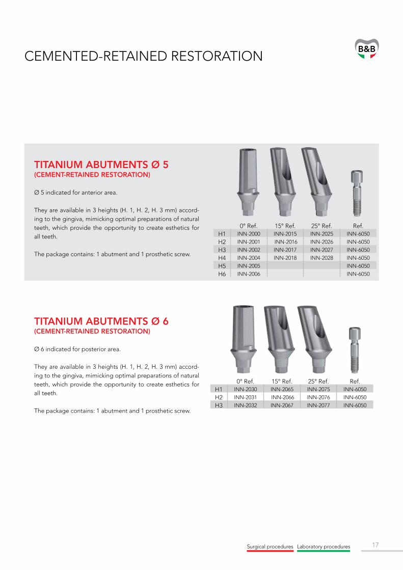
0° Ref. 15° Ref. 25° Ref. Ref.H1 INN-2000 INN-2015 INN-2025 INN-6050
H2 INN-2001 INN-2016 INN-2026 INN-6050
H3 INN-2002 INN-2017 INN-2027 INN-6050
H4 INN-2004 INN-2018 INN-2028 INN-6050
H5 INN-2005 INN-6050
H6 INN-2006 INN-6050
0° Ref. 15° Ref. 25° Ref. Ref.H1 INN-2030 INN-2065 INN-2075 INN-6050
H2 INN-2031 INN-2066 INN-2076 INN-6050
H3 INN-2032 INN-2067 INN-2077 INN-6050
CEMENTED-RETAINED RESTORATION
TITANIUM ABUTMENTS Ø 5(CEMENT-RETAINED RESTORATION)
Ø 5 indicated for anterior area.
They are available in 3 heights (H. 1, H. 2, H. 3 mm) accord-ing to the gingiva, mimicking optimal preparations of natural teeth, which provide the opportunity to create esthetics for all teeth.
The package contains: 1 abutment and 1 prosthetic screw.
TITANIUM ABUTMENTS Ø 6(CEMENT-RETAINED RESTORATION)
Ø 6 indicated for posterior area.
They are available in 3 heights (H. 1, H. 2, H. 3 mm) accord-ing to the gingiva, mimicking optimal preparations of natural teeth, which provide the opportunity to create esthetics for all teeth.
The package contains: 1 abutment and 1 prosthetic screw.
Surgical procedures Laboratory procedures

18
8
1 2
3
6
7
5
4
TITANIUM ABUTMENT CEMENTED RESTORATION
Fabricate the master cast including a gingival mask.
For optimal esthetic planning, model a full anatomical wax-up.
Make a silicone key over the full wax-up in order to define the optimal shape of the customized titanium abutment.
Place the Try-Inn abutment on the implant or implant analog.
This will aid in checking the gingival height (H.1, H.2, H.3 mm) and axial alignment of the potential restoration (0°, 15° e 25°).
(See page 16)
Modify the abutment as required.
Sandblast the modified abutment.
Once the ceramic cap will be cemented, the sandblasting increase the mechanical attach.
Wax an individual resin cap onto the abutment.
Place the pre selected abutment inside of the analog.

19
10
12
14
15 16
11
13
9
TITANIUM ABUTMENT CEMENTED RESTORATION
Check the wax-up with the silicone key.
Gently divest the customized abutment with ultrasound, water jet, pickling acid or a glass fiber brush.
Sandblast the metal crown in order to create a mechanical attach with the veneer.
Veneer the superstructure.
Position the abutment in the implant and tighten the screws to 25 Ncm using the hexagonal screwdriver along with the torque ratchet.
Investment.
Cast the framework in the conventional manner.
Verify that the metal crown fits precisely on the customized abutment.
Note: The long term success of the pros-thetic work depends on the accurate fit of the restoration. The entire procedure will have to be repeated, if casting errors occur.
Contour a wax model according to the ana-tomical circumstances of the individual cast.
Surgical procedures Laboratory procedures

20
ø 5
ø 5
ø 5
ø 5
ø 5
ø 5
ø 5 ø 5ø 5
CA107.08/1 CA107.08/2 CA107.08/3
CA107.09/1 CA107.09/2 CA107.09/3
CA107.10/1 CA107.10/2 CA107.10/3
H. 1
H. 1
H. 1
H. 2
H. 2
H. 2
H. 3
H. 3
H. 3
INN-6050
CASTABLE ABUTMENT - PLEXIGLASS
STRAIGHT ABUTMENTS
25° ANGLED ABUTMENTS
Complete with prosthetic screw
15° ANGLED ABUTMENTSComplete with prosthetic screw
Complete with prosthetic screw
INTENDED USE Cement-retained bridges via mesostructure(custom abutment technique).
CHARACTERISTICS - Easy-to-achieve esthetics due to individual
realization of the emergency profile and adaptation to the margin of the gingival contour.
- Superfluous cement easily removable by raising the cement margin using an individually designed mesostructure.
PROSTHETIC SCREW
IMPORTANT NOTE
- The use of castable abutments for Duravit implant system is not advisable, due to the difficulty to obtain a perfect conical fitting between implant and abutment.
- Use the castable abutment only in cases of extreme disparallelism.
- Do not use for a single crown.
The tightening of the prosthetic screw is realized with the 1.27 hex screwdriver and torque ratchet. For the final seating are recommended torques of 25 Ncm.
TIGHTENING:

21
1 2
3 4
5 6
87
Fabricate the master cast including a gingival mask.
For optimal esthetic planning, model a full anatomicalwax-up.
Make a silicone key over the full wax-up in order to define the optimal shape of the abutment.
Place the pre selectedabutment inside theanalog.
Modify the abutment as required.
Sandblast the modified abutment.
Wax an individual resin cap onto the abutment.
Investment of the resin cap.
Cast the framework in the conventional manner.
Sandblast the metal crown in order to create a mechanical attach with the veneer.
Veneer the superstructure.
Invest the customized abutment.
Surgical procedures Laboratory procedures

22
In order to avoid overflow of the cast-on alloy, clean the copings thoroughly prior to investment (removal of wax particles, insulating agents with a cotton pellet or brush moistened with alcohol).
Ensure that there is no wax on the delicate margin.The use of investment materials for rapid heating methods (speed investment materials) is not recommended.
When processing the investment material, follow the manufacturer’s instructions. Observe the recommended mixing ratio and preheating time exactly.
Make sure the screw channel and the internal configuration of the copings are filled with investment material from the bottom to the top in order to avoid air bubbles (see images).
INVESTMENT

23
INN-00652
INN-00651
INN-SCAN
0,5 mm
0,5 mm
4 mm
4 mm
INN-6050
MULTI-SCAN ABUTMENT
WITH TRADITIONAL METHODUtilization of a pre-fabricated castable placed on the abutment, that need to be adjusted and modeled with wax and/or acrylic, and fabrication of the portion of customized abutment through fusion.
WITH CAD/CAMScanbody allows to digitally get the abutment position on the model. The customized modelling includes a dedicated software and a laboratory working with drilling machine (CAM). Interface, link and B&B Dental scanbody are available for the following libraries:
INTENDED USE - Cemented-retained restoration.- Screw-retained restoration.- Single and multiple crowns
CHARACTERISTICS - Possibility of creating a transmucosal profile
customized for every single patient.- NIMETIC CEM (3M Espe), PANAVIA 21 (Kuraray
Medical Inc.) are the materials recommended for bonding the prosthetic manufacture.
- Conexa connection
NON-ROTATING MULTI SCAN
ROTATING MULTI-SCAN
Complete with prosthetic screw
Complete with prosthetic screw
The portion of the abutment can be customized as follows:
PROSTHETIC SCREW
The tightening of the prosthetic screw is realized with the 1.27 hex screwdriver and torque ratchet. For the final seating are recommended torques of 25 Ncm.
TIGHTENING:
Surgical procedures Laboratory procedures

24
H. 1 H. 2 H. 3
INN-00655 INN-00655/2 INN-00655/3
INN-6048
INN-6050
INN-6050
UCLA ABUTMENT
INTENDED USE- Cemented-retained restoration.- Screw-retained restoration.
CHARACTERISTICS - Titanium base.- Completely customized prostheses.- Use of CAD/CAM technology for the production
of zirconium abutments that has to be fixed on the central pillar.
- Conexa connection.
INTENDED USE - Ideal for overcasting.- Cemented-retained restoration.- Screw-retained restoration.- Use for single or multiple crowns.
CARACTERISTICS - Made of gold.- Completely customizable.- Model anatomically the gingiva.- Conexa connection.
CEREC BASE
UCLA ABUTMENT
Complete with prosthetic screw
Complete with prosthetic screw
TI BASE CEREC (Linea L)
Scanbodies are included in ScanPost and TiBase for the implant optical acquisition. The grey cap is used with omnicam system. The white cap is used with bluecam system. 2 different connections are available: S (code: 6431295) and L (code: 6431303).
NOTE:
PROSTHETIC SCREW
PROSTHETIC SCREW
TI BASE CEREC (Linea L)

25
7
1 2
3 4
5 6
8
MULTI-SCAN ABUTMENTSCREWABLE RESTORATION WITH THE TRADITIONAL METHOD
For optimal esthetic planning, model a full anatomical wax-up.
Make a silicone key over the full wax-up in order to define the optimal shape of the customized titanium abutment.
Place the multi-scan abutment on the analog and hand-tighten the screw using the hexagonal screwdriver.
Place the castable cilinder onto the multi-scan abutment.
Contour a wax model according to the ana-tomical circumstances of the individual cast.
Check the wax-up with the silicone key.
Check that the hole of the prosthetic screw is free of residues.
Casting and divestment.
Cast the framework in the conventional manner.
Verify that the metal crown fits precisely on the customized abutment.
Sandblast the metal crown in order to create a mechanical attach with the veneer.
Veneer the superstruture.
Position the abutment in the implant and tighten the screws to 25 Ncm using the hexagonal screwdriver along with the torque ratchet.
Cement the superstructure to the abutment.
Remove superfluous cement.
Surgical procedures Laboratory procedures

26
C
B
A
1
2
3
4
5
7
6
Shape the abutment on screen, using the software.
MULTI-SCAN ABUTMENTSCREWABLE RESTORATION WITH CAD/CAM
Fabricating the scan model.
Fabricate a master cast with the corresponding analog.
Option A: Fabricate a duplicate model made from scan plaster.
Option B: Cast the master cast directly by using scan plaster.
For optimal esthetic planning, model a full anatomical wax-up and scan it too.
To determine the spacing available for further processing, the silicone key can be viewed on-screen.
Put the scan model in the laser scanner.
Based on the design data, the customized structure is manufactured by a melling center.
Check the zirconium framework.
Veneer the superstructure.
Cement the zirconium cap to the multi-scan abutment.
Remove superfluous cement.
Tighten the prosthetic screw to 25 Ncm using the hexagonal screwdriver along with the torque ratchet.
27
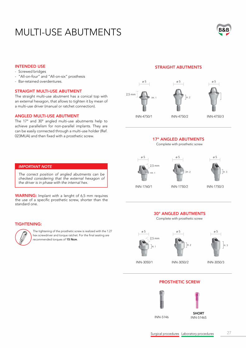
2,5 mmH. 1 H. 2
INN-4750/1 INN-4750/2 INN-4750/3
ø 5 ø 5 ø 5
INN-5146
H. 1 H. 2 H. 3
H. 3
2,5 mm
2,5 mm
INN-1760/1 INN-1750/2 INN-1750/3
INN-3050/1 INN-3050/2 INN-3050/3
H. 1H. 2
ø 5
ø 5
ø 5 ø 5
ø 5ø 5
INTENDED USE- Screwed bridges- “All-on-four” and “All-on-six” prosthesis- Bar-retained overdentures.
STRAIGHT MULTI-USE ABUTMENTThe straight multi-use abutment has a conical top with an external hexagon, that allows to tighten it by mean of a multi-use driver (manual or ratchet connection).
ANGLED MULTI-USE ABUTMENTThe 17° and 30° angled multi-use abutments help to achieve parallelism for non-parallel implants. They are can be easily connected through a multi-use holder (Ref. 023MUA) and then fixed with a prosthetic screw.
STRAIGHT ABUTMENTS
17° ANGLED ABUTMENTSComplete with prosthetic screw
30° ANGLED ABUTMENTSComplete with prosthetic screw
MULTI-USE ABUTMENTS
IMPORTANT NOTE
The correct position of angled abutments can be checked considering that the external hexagon of the driver is in phase with the internal hex.
PROSTHETIC SCREW
The tightening of the prosthetic screw is realized with the 1.27 hex screwdriver and torque ratchet. For the final seating are recommended torques of 15 Ncm.
TIGHTENING:
Surgical procedures Laboratory procedures
SHORT INN-5146S
WARNING: Implant with a lenght of 6,5 mm requires the use of a specific prosthetic screw, shorter than the standard one.

28
IMPORTANT NOTE
Il serraggio della vite protesica va effettuato con cricchetto dinamometrico e chiave protesica 1,27. Vengono raccomandati torques di 15 Ncm per l’alloggiamento finale.
SURGICAL ACCESSORIES
O-BALL MANUAL DRIVER 00440M
MULTI-USE HOLDER 023-MUA
MULTI-USE DRIVER
O-BALL TORQUE RATCHET DRIVER
INN-00637
MUA ANALOG INN-00586
TEMPORARY ABUTMENT
INN-5144Complete with
connecting screw
CONNECTING SCREW
INN-6051
CASTABLE ABUTMENT
INN-5145Complete with
connecting screw
SPHERICAL ANCHOR Ø 2.3
INN-1023
SCAN BODY Compatible with
the following libraries:3Shape/ Exocad/Dental
Wings/Carestream/ Sicat
OPEN TRAY TRANSFERINN-00610
Complete with transfer screw
CLOSED TRAY TRANSFERINN-00611
LABORATORY ACCESSORIES
LABORATORY INSTRUMENTS
HEALING CAP SCREW
INN-6030
MUA POST SCREWINN-00612

29
1
3 4
2
87
5 6
BRIDGESCREWABLE PROSTHESIS TAKING IMPRESSION
Position the multi-use abutments in the implants.
Tighten them to 25 Ncm using the screw driver (ref. INN- 00637) along with the torque ratchet.
Screw the close tray transfers onto the multi-use abutments.
Take the impression using an elastomeric impression material (polyvinyl siloxane or polyether rubber).
Note: Due to its low tensile strength, hydrocolloid is not suitable for this application.
Once the material is cured, carefully remove the tray.
The elastomer will take the conical shape of the close tray transfer for a safety reposition of the analog.
Unscrew close tray transfers from the mouth and send all to the dental technician.
Screw the healing caps onto the multi-use abutments in order to keep opened the soft tissues until the final restoration is inserted.
Screw the transfer onto the multi-use analog.
Push the transfer and analog in the tray. It is now firmly seated in the impression tray.
A gingival mask should always be used to ensure that the emergence profile of the crown is optimally contoured.
Fabricate the master cast using standard methods and type 4 dental stone (DIN 6873).
Surgical procedures Laboratory procedures

30
11
10
1615
9
12
91413
TEMPORARY PROSTHESIS
Place the temporary cylinder on the multiuse analog.
This will aid in checking the gingiva height
Sandblast and coat with opaque.
Make a silicon key over the full wax-up in order to fine the optimal shape of the customized temporary abutment.
Shorten the temporary abutment and then check the heights with the silicone key previously cut.
For optimal esthetic planning, model a full anatomical wax-up.
Fill the silicon key with acrylic resin and press it on the model and use a standard technique to fabricate the temporary crown.
Remove excess acrylic.
Polish and clean the temporary restoration.
Reopen the screw channel.
Place the temporary restoration on the implant and tighten the screw with torques of 25 Ncm.

31
9 10
11 12
13 14
1615
Fabricate the master cast including a gingival mask.
Place the castable cylinder on the analogs and hand tighten the occlusal screws using the screw driver.
Note: Do not over tighten the castable cylinder.
Shorten the castable cylinder to the height of the occlusal floor according to the individual situation.
Fabricate the superstructure on the abutments using standard modeling methods.
Make sure that the wax layer on the abutment is sufficiently thick (at least 0.7 mm).
Check that the wax framework of the bridge is absolutely tension-free before investing the framework.
This is accomplished according to commonly known bridge techniques.
Check the wax-up with the silicone key.
DEFINITIVE PROSTHESIS
For optimal esthetic planning, model a full anatomical wax-up.
Make a silicone key over the full wax-up in order to define the optimal shape of the customized titanium abutment.
Surgical procedures Laboratory procedures

32
17 18
19 20
21
23
22
Invest the bridge framework according to standard methods without using wetting agents.
Gently divest the customized abutment with ultrasound, water jet, pickling acid or a glass fiber brush.
Control for tension-free fitting on the master cast.
If the bridge is not tension-free and wiggles, cut the bridge and resplint it tension free.
Sandblast and coat the superstructure.
Veneer the superstructure.
Do an additional try-on of the tension-free fit of the framework in the patient’s mouth.
Tighten the occlusal screws to 25 Ncm, using the hexagonal screwdriver along with the torque ratchet.

33Surgical procedures Laboratory procedures
130DIN1 130DIN2 130DIN3 130DIN4 130DIN5
H. 1 H. 2 H. 3 H. 4H. 5
EQUATOR ANCHOR SYSTEM
LABORATORY ACCESSORIES
COMPLETE SET INCLUDES:1 Anchor abutment
1 Stainless steel housings
1 Retentive caps - violet “strong”
1 Retentive caps - white “standard”
1 Retentive caps - pink “soft”
1 Retentive caps - yellow “extra-soft”
1 Processing cap - black
+
1 METAL INSERTION TOOL FOR CAPS
185IAC
1 BLUE PLASTIC “MULTIUSE”
INSERTION TOOL 124ICP
1 SQUARE DRIVER CONNECTOR FOR
TORQUE760CE
1 OT-EQUATOR SQUARESCREWDRIVER FOR
IMPLANT ABUTMENT(SQUARE 1,25MM)
774CHE
SURGICAL INSTRUMENTS
PROCESSING CAPS - BLACK
140CEN (4 pieces)
IMPRESSION COPINGS
144MTE (2 pieces)
LABORATORY ANALOGS
144AE (2 pieces)
PULL-OFF IMPRESSIONCOPING
044CAIN (2 pieces)
CAPS WITH METAL HOUSING
STAINLESS STEEL HOUSINGS
141CAE (2 pieces)
RETENTIVE CAPS STRONG
140CEV (4 pieces)
RETENTIVE CAPSSTANDARD
140CET (4 pieces)
RETENTIVE CAPSSOFT
140CER (4 pieces)
RETENTIVE CAPSEXTRASOFT
140CEG (4 pieces)

34
7
1
3
5
2
4
6
Select the height of the Equator abutment.
The top margin of the abutment should be 1 mm above the mucosa.
Tighten the abutment to 25 Ncm using the ratchet along with the torque control device.
Place the impression copings on the Equator abutments.
Take the impression uti-lizing the mucodynamic technique (vinyl poly-siloxane or polyether rubber).
Send the impression to the dental laboratory.
Place the analogs inside the impression copings.
A gingival mask should always be used to en-sure that the emergence profile of the crown is optimally contoured.
Fabricate the master cast using standard methods and type 4 dental stone (DIN 6873).
Place the denture caps with the black processing males onto the Equator abutments, or the analogs in the master cast.
The dental technician returns the completed Equator overdenture to the doctor’s office for final placement.
EQUATORINDIRECT TECHNIQUE

35
ø 1,8
ø 2,5
ø 1,8
ø 2,5
ø 1,8
ø 2,5
ø 2,3 ø 2,3ø 2,3 ø 2,3ø 2,3 ø 2,3
INN-1060 INN-1061 INN-1062 INN-1064 INN-1065 INN-1066
INN-1050 INN-1051 INN-1052
INN-1040 INN-1041 INN-1042
H. 1
H. 1
H. 4H. 1
H. 2
H. 2
H. 5
H. 2
H. 3
H. 3
H. 6
H. 3
Ø 2
,3Ø
1,8
Ø 2
,5
INN-00624INN-00621
INN-00623
INN-00622
INN-00625
INN-00626
INTENDED USEDentures retained by implants in the mandible and maxilla.
CHARACTERISTICS- Simple.- Divergence compensation up to 20° between two
implants.- Minimum height for limited occlusal space.- Reliable.- Excellent long-term performances due to high
wear on resistance of components.
SPHERICAL ANCHOR SYSTEM
SPHERICAL ANCHORS O-BALL ANALOG
TRANSFERT
Surgical procedures Laboratory procedures

36
SOFTINN-00629/1
MEDIUMINN-00629
HARDINN-00629/3
SOFTINN-00630/S
MEDIUMINN-00630
HARDINN-00630/H
Ø 1.8 METAL HOUSINGSThe prosthetic housings are available in three different retentions, achieved by using the appropriate silicon o-ring and metal housing.
NOTE: The metal housing is sold individually, without having a plastic cap inside.
NOTE: The metal housing is sold individually, without having a plastic cap inside.
NOTE: The metal housing contains inside the plastic cap.
O-RING (BIG)MD-3005/1 (5 pieces)
O-RING (SMALL)MD-3005 (5 pieces)
Ø 1.8 PLASTIC CAPS AND METAL HOUSING
Ø 2.3 PLASTIC CAPS AND METAL HOUSING
Ø 2.5 PLASTIC CAPS AND METAL HOUSING
Ø 2.3 ONLY PLASTIC CAPS 6pcs each package
SOFT RETENTIONMD-3004/1
MEDIUM RETENTION MD-3004
HARD RETENTIONMD-3004/2
ELASTIC 049PCM (6 pieces)
SOFT040CRM SN
(6 pieces)
EXTRA SOFT060CRM AY (6 pieces)
041CAM (2 pieces)
ELASTIC 049PCN
(6 pieces)
SOFT040CRN SN
(6 pieces)
EXTRA SOFT060CRN AY (6 pieces)
041CAN (2 pieces)

37
2
4
6
7
1
3
5
Select the height of the O-ball abutment.
The top margin of the abutment should be 1 mm above the mucosa.
Tighten the abutment to 25 Ncm using the ratchet along with the torque control device.
Place the metal housing onto the spherical anchors.
Take the impression uti-lizing the mucodynamic technique (vinyl poly-siloxane or polyether rubber).
Send the impression to the dental laboratory.
Once the material is cured, carefully remove the tray.
The impression cap remains in the impres-sion material.
A gingival mask should always be used to en-sure that the emergence profile of the crown is optimally contoured.
Fabricate the master cast using standard methods and type 4 dental stone (DIN 6873).
Place the denture caps onto the O-ball abutments, or the analogs in the master cast.
The dental technician returns the completed o-ball overdenture to the doctor’s office for final placement.
O-BALL ABUTMENTINDIRECT TECHNIQUE
Surgical procedures Laboratory procedures

38
2
1
4
3
1
2
4
3
Select the height of the Equator abutment.
The top margin of the abutment should be 1 mm above the mucosa.
Tighten the abutment to 25 Ncm using the ratchet along with the torque control device.
Place the protection disc first and then the metal cap.
Hollow out the existing denture base in the areas of the denture caps.
EQUATORDIRECT TECHNIQUE
O-BALL ABUTMENTDIRECT TECHNIQUE
The dental technician returns the completed o-ball overdenture to the doctor’s office for final placement.
Select the height of the O-Ball abutment.
The top margin of the abutment should be 1 mm above the mucosa.
Tighten the abutment to 25 Ncm using the ratchet along with the torque control device.
Place the protection disc first and then the metal cap.
Hollow out the existing denture base in the areas of the denture caps.
The dental technician returns the completed o-ball overdenture to the doctor’s office for final placement.

39
BAR SYSTEM
Surgical procedures Laboratory procedures
OT BAR
PLASTIC CLIP
INSTRUMENTS
CASTABLE BAR(2 pcs)
0220BB
GINGIVAL CONNECTOR (OPTIONAL)
POSITIONING CLIP A (4 pcs)
023CPA
POSITIONING CLIP B (4 pcs)
02CPB
CASTABLE BOX (4 pcs)
025CPB
MEDIUMRETENTION
(4 pcs)027CRG
SOFTRETENTION
(4 pcs)026CRR
SHORT DRIVER00578/S
TOOL FOR INSERTING CLIP029OIC
KEY FOR PARALLELOMETER028OCP

40
7
1 2
3 4
5 6
8
BAR SYSTEM SCREWABLE PROSTHESIS IMPRESSION TAKING
Select the height of the multi-use abutment.
The top margin of the abutment should be 1 mm above the mucosa.
Tighten the abutment to 25 Ncm using the ratchet along with the torque control device.
Place the impression post accurately into the implant and tight the transfer screw by hand (Fig. A) or using the hexagonal screwdriver.
Make perforations in the custom-made impression tray.
Take the impression using an elastomeric impression material (polyvinyl siloxane or polyether rubber).
Note: Due to its low tensile strength, hydrocolloid is not suitable for this application.
Once the material is cured, loosen the transfer screws and remove the tray.
Fix the analog in the impression using the transfer screw.
Analogs fixed inside the transfer.
A gingival mask should always be used to ensure that the emergence profile of the crown is optimally contoured.
Fabricate the master cast using standard methods and type 4 dental stone (DIN 6873).
41
9 10
11
13
12
15
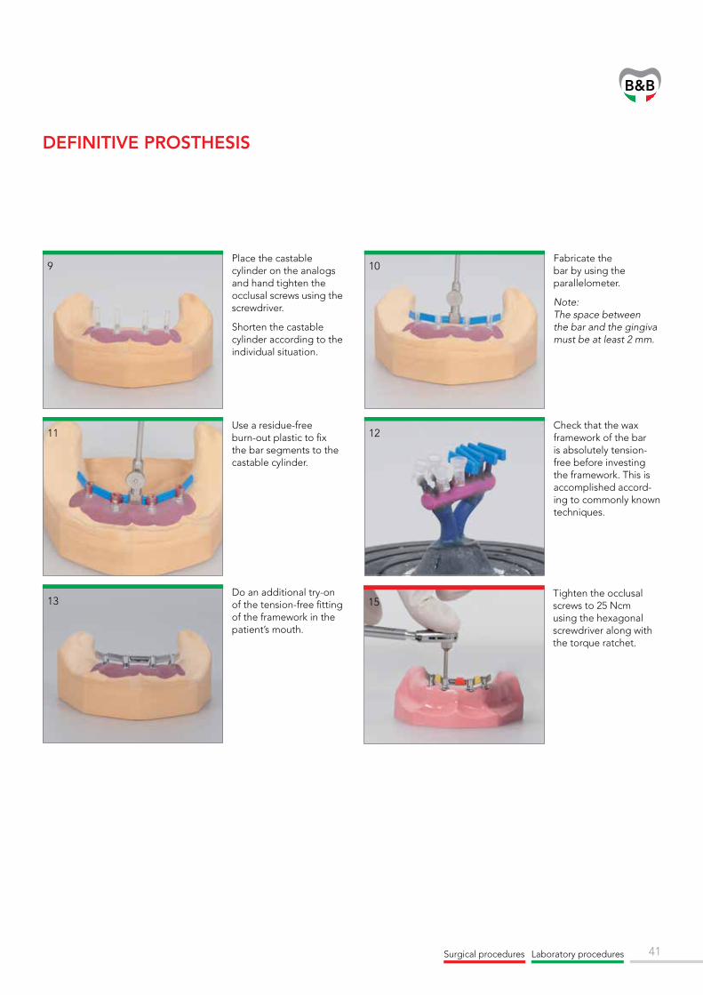
DEFINITIVE PROSTHESIS
Place the castable cylinder on the analogs and hand tighten the occlusal screws using the screwdriver.
Shorten the castable cylinder according to the individual situation.
Fabricate the bar by using the parallelometer.
Note: The space between the bar and the gingiva must be at least 2 mm.
Use a residue-free burn-out plastic to fix the bar segments to the castable cylinder.
Check that the wax framework of the bar is absolutely tension-free before investing the framework. This is accomplished accord-ing to commonly known techniques.
Do an additional try-on of the tension-free fitting of the framework in the patient’s mouth.
Tighten the occlusal screws to 25 Ncm using the hexagonal screwdriver along with the torque ratchet.
Surgical procedures Laboratory procedures

42


implant companyB&B DENTAL
Système Qualité Certifié
UNI EN ISO 13485
EN ISO13485
Sistema Qualità CertificatoUNI EN ISO 13485
Via San Benedetto, 1837 - 40018 San Pietro in Casale (BO) ItalyTel. +39 (0) 51.81.13.75 - Fax +39 (0) [email protected] - www.bebdental.it
REV.
03
- 01/
07/2
016