Embed Size (px)
Citation preview

1
This document provides instruction for the prosthetist in the installation and use of the system. A separate document, LimbLogic VS Patient Information, is included with each system and should be provided to the patient upon delivery of a prosthesis containing the LimbLogic VS.
The Vacuum Pump and fob included in this package are electronically keyed together and can be used only with each other.
LimbLogic VS - 1600 Series is now waterproof.
Prosthetist’s Guide

2
This pump is only designed to move air; use of Vaseline® or similar lubricating creams inside the socket will clog the pump. Do not allow foreign substances to be pulled through the Vacuum Pump. This may impair function of your vacuum system.
Do not allow acetone to contact the Vacuum Pump or fob.
The LimbLogic VS is not intended to be used as the only means of attachment of prosthesis to patient.
All LLVS components have passed safety testing for use as medical devices. Radio enabled devices transmit with a power of less that one milliwatt and comply with United States and international guidelines for low power transceivers. If LLVS components will be used around safety critical devices such as pacemakers or defibrillators, consult the manufacturer for appropriate usage instructions. Consult the section on Regulatory Information for more information on safety and compliance.
3
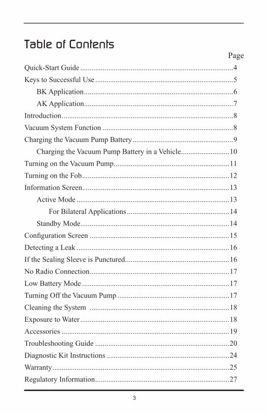
Table of ContentsPage
Quick-Start Guide ..................................................................................4
Keys to Successful Use ..........................................................................5
BK Application ................................................................................6
AK Application ................................................................................7
Introduction ............................................................................................8
Vacuum System Function ......................................................................8
Charging the Vacuum Pump Battery ......................................................9
Charging the Vacuum Pump Battery in a Vehicle ..........................10
Turning on the Vacuum Pump ..............................................................11
Turning on the Fob ...............................................................................12
Information Screen ...............................................................................13
Active Mode ..................................................................................13
For Bilateral Applications .......................................................14
Standby Mode ................................................................................14
Configuration Screen ...........................................................................15
Detecting a Leak ..................................................................................16
If the Sealing Sleeve is Punctured ........................................................16
No Radio Connection ...........................................................................17
Low Battery Mode ...............................................................................17
Turning Off the Vacuum Pump ............................................................17
Cleaning the System ...........................................................................18
Exposure to Water ................................................................................18
Accessories ..........................................................................................19
Troubleshooting Guide ........................................................................20
Diagnostic Kit Instructions ..................................................................24
Warranty ...............................................................................................25
Regulatory Information ........................................................................27

4
Quick-Start Guide
orPress and hold center button until LimbLogic VS logo appears in display
3. Information about the system is displayed.
current vacuum level
current upper set point
(press up and down buttons to adjust, and center button
to confirm)
Vacuum Pump battery charge level
4. To enter Standby Mode:
Press center button
until appears
Standby Mode
Press center button
until appears
To resume vacuum regulation:
2. Start regulating the vacuum.
Overview
5. Turn off the Vacuum Pump.
1. Turn on the Vacuum Pump.
Press one time
Press two times
Press one more time

5
Keys to Successful Use
1. Fabricate a non-porous Total Surface Weight Bearing socket using a LimbLogic VS 4-Hole Attachment Plate. This is critical to the proper operation of the system. Be sure to follow the fabrication instructions provided with the 4-Hole Attachment Plate.
Prior to delivering the prosthesis, you may want to use the Diagnostic Kit (LLV-1300) to confirm that there are no leaks in the system.
2. Fully charge the Vacuum Pump. (Refer to “Charging the Vacuum Pump Battery” on page 9.)
3. Properly secure the fully charged Vacuum Pump to the socket, Vacuum Plate (LLV-01043), or Vacuum Pyramid (LLV-01044) with M6 flathead screws. Tighten the screws to 9 ft-lbs (12 Nm).
4. Assemble the prosthesis, inserting one end of the exhaust port tubing into the exhaust port. Attach the other end of the tubing as desired.
5. Have the patient don an Alpha® Liner, the prosthesis, and an Alpha Sleeve. For the best seal proximally, the patient should fold over the top edge of the liner and roll the sleeve up onto the folded edge to create a gel-to-gel seal, as shown in the figures on pages 6 and 7.
Overview
Exhaust Port Exhaust Port Tubing

6
Gel side of Alpha Liner
Gel side of Flex Sleeve
Fabric side of Flex Sleeve
Overview
Figure 1:Folding over the top edge of the liner
Socket
Alpha Flex Sleeve
Fabric side of Alpha Liner
Gel side of Alpha Liner
BK Application
The patient should don an Alpha Liner and Alpha Flex Sleeve as shown below.
Figure 2:Rolling the sleeve up onto the folded edge of the liner
7
Overview
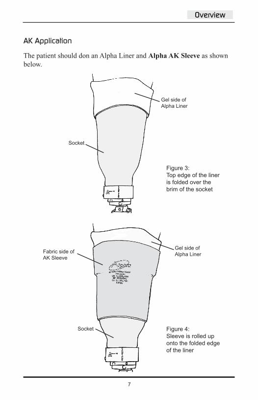
AK Application
The patient should don an Alpha Liner and Alpha AK Sleeve as shown below.
Figure 3:Top edge of the liner is folded over the brim of the socket
Socket
Gel side of Alpha Liner
Gel side of Alpha LinerFabric side of
AK Sleeve
Figure 4:Sleeve is rolled up onto the folded edge of the liner
Socket
8
Introduction
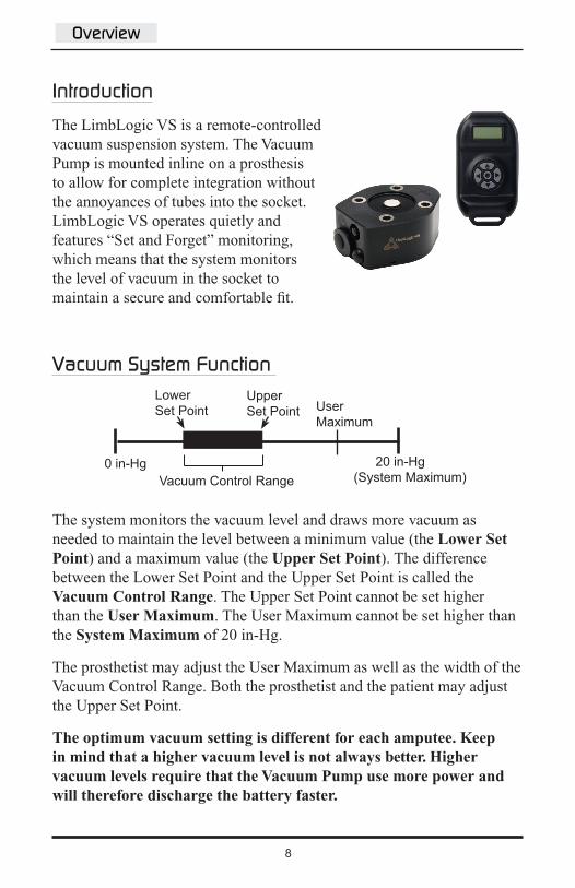
The LimbLogic VS is a remote-controlled vacuum suspension system. The Vacuum Pump is mounted inline on a prosthesis to allow for complete integration without the annoyances of tubes into the socket. LimbLogic VS operates quietly and features “Set and Forget” monitoring, which means that the system monitors the level of vacuum in the socket to maintain a secure and comfortable fit.
Vacuum System Function
The system monitors the vacuum level and draws more vacuum as needed to maintain the level between a minimum value (the Lower Set Point) and a maximum value (the Upper Set Point). The difference between the Lower Set Point and the Upper Set Point is called the Vacuum Control Range. The Upper Set Point cannot be set higher than the User Maximum. The User Maximum cannot be set higher than the System Maximum of 20 in-Hg.
The prosthetist may adjust the User Maximum as well as the width of the Vacuum Control Range. Both the prosthetist and the patient may adjust the Upper Set Point.
The optimum vacuum setting is different for each amputee. Keep in mind that a higher vacuum level is not always better. Higher vacuum levels require that the Vacuum Pump use more power and will therefore discharge the battery faster.
Vacuum Control Range0 in-Hg
User Maximum
Lower Set Point
Upper Set Point
20 in-Hg (System Maximum)
Overview

9
Charging the Vacuum Pump Battery
1. Remove the cap from the charging port on the Vacuum Pump.
2. Insert the charging plug into the charging port as follows:
a) Gently insert the plug into the port, holding the black plastic portion of the plug, with just enough force to feel the plug touch the port.
b) Align the green alignment marks on the charging port and the charging plug.
The charging plug can only be inserted into the Vacuum Pump charging port in one orientation. Forcing the plug will damage the plug, will possibly damage the vacuum system, and will void the warranty.
3. Plug the charger into a power outlet. The blue light on the two-pronged adapter will light, followed by the green LED. The fob will display the battery charging indicator.
If the green LED does not light, press and hold the reset button until the light comes on.
4. When charging is complete, the green LED will flash. Disconnect the power cord from the Vacuum Pump and from the power outlet.
charging port
Charger Vacuum Pump To AC outlet
Green LEDSOLID = chargingFLASHING = charged
charging plug
reset button
Align the green mark on the plug with the green mark on the port.
Overview
charger node

10
5. Reinstall the cap onto the charging port on the Vacuum Pump.
Use ONLY an Ohio Willow Wood charger. For LLV-01042 series Vacuum Pumps use Ohio Willow Wood charger part number LLV-01011. For LLV-01040 series Vacuum Pumps use Ohio Willow Wood charger part number LLV-01010. Use of any other charger may result in damage to the Vacuum Pump or the charger or both.
If the charger needs to be reset, press the reset button. With normal usage, the rechargeable battery should last for the life of the product.
Charging the Vacuum Pump Battery in a Vehicle
To use a vehicle’s power to charge the Vacuum Pump, you must purchase a Power Inverter rated at 75 Watts or less to convert the vehicle’s 12V DC power to 120V AC. Examples of acceptable Power Inverters include the Digital Concepts™ 75 Watt Portable Power Inverter (available from general retailers) and the Enercell™ 75 Watt Power Inverter (available from Radio Shack®; item number 22-133).
1. Plug the Power Inverter into the vehicle’s cigarette lighter socket.
2. Connect the charger to the Vacuum Pump.
3. Plug the charger’s two-pronged adapter into the Power Inverter’s three-pronged receptacle.
Overview

11
Turning on the Vacuum Pump
Press the on/off button on the Vacuum Pump one time. The pump will vibrate four times.
Note: if the pump has just been unplugged from the charger, the button does not need to be pressed.
When you are ready for the pump to begin regulating the vacuum, press the on/off button again (or turn on the fob, as described on the next page). The pump will operate until the preselected vacuum level is reached.
Overview
on/off button

12
Turning on the Fob
Up/down buttons: adjust vacuum setting
Center button: apply setting
Right/left buttons: toggle between right and left Vacuum Pumps (bilateral only)center
button
right button
up button
left button
Overview
down button
Press and hold the center button on the fob until the LimbLogic VS logo appears and the display has reached the desired brightness.
Release the button. If the Vacuum Pump is charged and powered, the Information Screen will be displayed.
The fob shuts off after one minute of non-use. This will not affect the Vacuum Pump. Press and hold the center button to restart the fob.

13
Information Screen
The Information Screen indicates important details about the operation of the system.
The vertical bars inside the battery symbol on the right side of the screen indicate the amount of charge left in the Vacuum Pump battery.
As the battery is discharged, the bars disappear from left to right.
A) Active Mode
When numbers are displayed to the left of the battery symbol, as shown below, the system is in Active Mode. In this mode, the Vacuum Pump activates as needed to maintain the vacuum settings.
You or the patient may use the up/down buttons to adjust the Upper Set Point as desired. This is the only setting the patient may adjust. The Upper Set Point cannot be set higher than the User Maximum.
Press the center button to save the change. The hourglass symbol will appear to indicate that the setting is being saved.
current upper set point current vacuum level
Overview

14
For bilateral applications:
The Information Screen displays right and left indicators to show which pump is currently communicating with the fob.
Use the right/left buttons to select the right or left Vacuum Pump, then press the center button to save your selection.
The LimbLogic VS logo will appear, followed by the Information Screen for the selected pump.
In this example, the fob is communicating with the LEFT pump
In this example, the fob is communicating with the RIGHT pump
B) Standby Mode
Allows you to turn off the pump temporarily to prevent the pump from regulating the vacuum.
To enter Standby Mode, press and hold the center button until the hourglass symbol appears.
The standby indicator will then appear to indicate that the pump is not regulating.
To return to Active Mode, press and hold the center button until the hourglass symbol appears.
After six hours of Standby Mode without radio communication, the unit will turn off. To turn the pump back on, either press the on/off button on the Vacuum Pump one time or plug in the charger.
Keep in mind that a Vacuum Pump in Standby Mode will continue to use the pump battery.
Overview

15
Configuration Screen
The system is shipped with the User Maximum set at 20 in-Hg and the Vacuum Control Range set at 6 in-Hg. If these settings are not sufficient for your patient, you may adjust them as follows:
With the Information Screen displayed, press the left and right buttons simultaneously.
After the warning screen flashes, you will see the Configuration Screen.
Use the right and left buttons to adjust the User Maximum. The User Maximum cannot be set higher than 20 in-hg.
Press the up or down button to scroll to the next screen.
Use the right and left buttons to adjust the Vacuum Control Range. The Vacuum Control Range cannot be set lower than 4 in-hg.
Note: Increasing the Vacuum Control Range and decreasing the User Maximum setting may reduce pump cycling and may increase pump battery life.
Press the center button to exit the Configuration Screen and save all current settings.
In this example, the Vacuum Control Range is set at 4 in-Hg
In this example, the User Maximum is set at 18 in-Hg
Overview
16
Detecting a Leak
If the leak indicator appears when the patient initially dons the prosthesis, the patient should restart the pump.
If the leak indicator appears frequently while the patient is walking, use the Diagnostic Kit (LLV-1300) to determine the source of the leak.
To resume automatic vacuum regulation after a leak has been detected:
• Press the center button on the fob until the hourglass symbol appears,
or
• Press the on/off button on the Vacuum Pump one time.
If the Sealing Sleeve is Punctured
The latex sleeves (LLS-3N, LLS-4N, or LLS-5N) in the Diagnostic Kit are to be used ONLY as a diagnostic tool for locating the source of a leak. If a leak is fixed by replacing a sealing sleeve with a latex sleeve, then the patient should receive a new sealing sleeve immediately. The patient should NOT be sent home with a latex sleeve, because the mineral oil in the Alpha gel causes the latex to lose its elasticity.
Overview

17
No Radio Connection
If the No Radio Connection indicator appears:
• make sure the Vacuum Pump has been turned on
• make sure the Vacuum Pump battery has been charged
• make sure the fob is within 3 feet of the Vacuum Pump
• make sure the fob is more than 3 inches away from the Vacuum Pump
If the No Radio Connection indicator still appears, contact Ohio Willow Wood.
Low-Battery Mode
If the Vacuum Pump battery has less than 15% of its capacity remaining, the Vacuum Pump enters a “stutter” mode. (Stutter mode is when the pump quickly turns on and off when pulling vacuum.) Charge as soon as possible.
The fob will display the battery charging indicator when the unit is plugged into the charger.
Turning off the Vacuum Pump
Press the on/off button on the Vacuum Pump two times. The Vacuum Pump will vibrate twice.
If the current vacuum level is near the current Upper Set Point, the Vacuum Pump may skip the vibrations to prevent the vacuum level from exceeding the Upper Set Point.
Overview

18
Cleaning the SystemOnce a month, the patient should pour 1/8 cup of distilled water or rubbing alcohol into the socket, place the end of the exhaust port tubing into a cup, and activate the Vacuum Pump. Use ONLY distilled water or rubbing alcohol to clean the system.
Do not use acetone or similar chemicals to clean the system.
Please demonstrate this procedure for the patient before sending the patient home with the system.
Exposure to WaterThe Vacuum Pump is waterproof in fresh water up to a depth of 10 feet or 3 meters for up to 12 hours. The Vacuum Pump should not be submersed in salt water. Be sure to dry off the Vacuum Pump if it is exposed to rain or other moisture.
The fob is not water resistant. Submersion of the fob will void the warranty.
Overview

19
Accessories
Cosmesis KitThe Cosmesis Kit (LLV-01046) extends the Vacuum Pump’s charging port and on/off button so that they are flush with the surface of a cosmetic cover. The kit also includes a hose barb for routing the exhaust tube into the foot shell.
Vacuum Plate/PyramidThe Vacuum Plate (LLV-01043) and Vacuum Pyramid (LLV-01044) can be used for attaching the Vacuum Pump in line with other endoskeletal components, instead of attaching the pump directly to the socket.
Overview
Vacuum Plate Vacuum Pyramid

20
Problem ActionThe pump does not vibrate when the on/off button is pressed once and the charger is not connected to the pump.
• The pump’s internal battery may not be charged. Charge the pump with the charger for at least 30 minutes and try again.
• The on/off button could be damaged. Verify that the rubber boot is intact and hasn’t been torn from impact. Contact Ohio Willow Wood if the switch needs to be replaced.
• The pump may have ben exposed to a large static discharge. Plug in the charger and press the reset button to reset the pump. The charger does not need to be plugged into an outlet.
Pressing the pump button, waiting for the start-up vibrations, and then pressing the button again does not start the pump.(To prevent excessive vacuum, the pump will not vibrate if it is already holding a vacuum when it is started up.)
• Do not press the on/off button too quickly. Press the button for one second, then release for one second before pressing again, so that the system recognizes separate button presses.
• The pump’s internal battery may not be charged. Charge the pump with the charger for at least 30 minutes and try again.
• The pump could already be in automatic mode. Pressing twice when the unit is in automatic mode or standby mode will turn the unit completely off. Wait 15 seconds, then press the on/off button once and verify that the pump vibrates to indicate it is in standby mode. After vibration, press a second time to transition the pump to automatic mode.
• The pump may have ben exposed to a large static discharge. Plug in the charger and press the reset button to reset the pump. The charger does not need to be plugged into an outlet.
Troubleshooting Guide
Overview
continued on next page

21
Problem Action
Pump battery does not maintain charge for a full day.
• Ensure that the system is properly sealed.• Ensure that the battery has been charged for
at least 4 hours.• The pump may have ben exposed to a large
static discharge. Plug in the charger and press the reset button to reset the pump. The charger does not need to be plugged into an outlet.
• Ensure that your socket does not leak excessively.
The fob does not communicate with the pump. The LimbLogic VS logo appears and is followed by the No Radio Connection icon.
• Make sure the pump is on by pressing the on/off button once and verify that the pump vibrates in recognition of the button activation. Wait one minute for the fob screen to turn off. Press the fob center button again.
• The fob may be too close or too far from the pump. Place the fob about 2 feet away from the pump, and press the fob center button again.
• The pump’s internal battery may not be charged. Charge the pump with the charger for at least 30 minutes and try again.
• Does the patient have the correct fob-pump combination? The fob and pump are electronically matched during the production process. Contact Ohio Willow Wood with the serial number of the fob and serial number of the pump to verify that the set is matched.
• The pump may have ben exposed to a large static discharge. Plug in the charger and press the reset button to reset the pump. The charger does not need to be plugged into an outlet.
continued on next page
Overview

22
Problem ActionThe green LED on the charger node does not illuminate or blink when the charger is plugged into vacuum pump and AC outlet.
• Make sure that the green marks on the charging port and the charging plug are aligned (page 9). Do not force the connection.
• The pins on the charger plug may be bent. Unplug the charger from the vacuum pump and inspect the pins. Do NOT try to straighten pins while charger is plugged into an AC outlet! If the pins are bent or broken, contact Ohio Willow Wood.
• With the charger plugged into an AC outlet and the pump, press and hold the reset button on the charger node for 5 seconds, then release. If the green LED does not blink or turn solid within 5 seconds after the button release, contact Ohio Willow Wood.
• If charger plug pins have been bent or the plug has been forced into pump, the internal electronics of the pump can be damaged, or the green LED on the charger could be damaged. Use the fob to check the pump battery level, then charge the pump for 2 hours and re-check the battery level to verify that the level has increased. If the level has not increased, contact Ohio Willow Wood.
continued on next page

23
Problem ActionPressing the center of the button of the fob does not display the LimbLogic VS logo.
The fob battery may need to be reset. Remove the back cover of the fob per the instructions in the Patient Information booklet, then remove and reinstall the battery. If the problem persists, the battery is likely dead and must be replaced per the instructions in the Patient Information booklet.
The blue LED light on the charger does not illuminate when plugged into the wall.
• The AC electricity to the wall outlet may not be turned on. Try plugging the charger into a different non-switched wall outlet or in another room.
• The configurable prong may not be seated properly in the back of the charger’s two-pronged adapter. Unplug the charger from the AC outlet. Remove the charger’s prong using the sliding latch on the back of the adapter. Verify that the metal contacts are springy and are not completely flat against the adapter. Re-install the plug prongs.
The pump makes a “zip zip zip” sound as it controls the vacuum.
The system is leaking, but not yet at a rate that triggers the Leak Detection symbol. Wash the sealing sleeve of debris around the sealing surface, and remove any dirt or debris from the proximal sealing gasket and the pump’s sealing surface. If the leak is still present, use the Diagnostic Kit (LLV-1300) to determine the source of the leak. Refer to the Diagnostic Kit instructions on the next page.
Overview
24
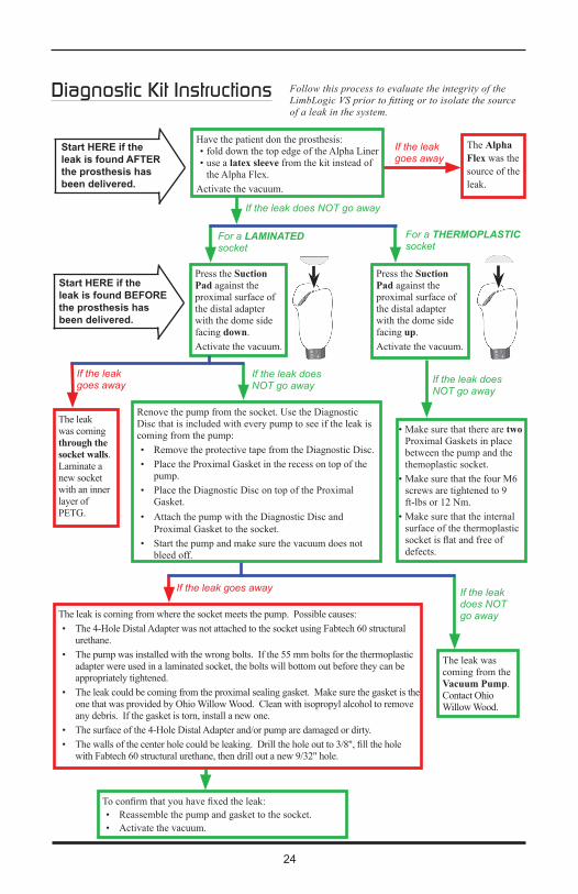
Diagnostic Kit Instructions
Press the Suction Pad against the proximal surface of the distal adapter with the dome side facing down.Activate the vacuum.
Have the patient don the prosthesis:• fold down the top edge of the Alpha Liner• use a latex sleeve from the kit instead of
the Alpha Flex.Activate the vacuum.
Press the Suction Pad against the proximal surface of the distal adapter with the dome side facing up.Activate the vacuum.
The leak was coming through the socket walls. Laminate a new socket with an inner layer of PETG.
To confirm that you have fixed the leak:• Reassemble the pump and gasket to the socket. • Activate the vacuum.
• Make sure that there are two Proximal Gaskets in place between the pump and the themoplastic socket.
• Make sure that the four M6 screws are tightened to 9 ft-lbs or 12 Nm.
• Make sure that the internal surface of the thermoplastic socket is flat and free of defects.
The leak was coming from the Vacuum Pump. Contact Ohio Willow Wood.
Follow this process to evaluate the integrity of the LimbLogic VS prior to fitting or to isolate the source of a leak in the system.
The Alpha Flex was the source of the leak.
Start HERE if the leak is found AFTER the prosthesis has been delivered.
Start HERE if the leak is found BEFORE the prosthesis has been delivered.
If the leak does NOT go away
For a LAMINATED socket
For a THERMOPLASTIC socket
If the leak does NOT go away
If the leak does NOT go away
If the leak does NOT go away
If the leak goes away
If the leak goes away
If the leak goes away
Renove the pump from the socket. Use the Diagnostic Disc that is included with every pump to see if the leak is coming from the pump:• Remove the protective tape from the Diagnostic Disc. • Place the Proximal Gasket in the recess on top of the
pump.• Place the Diagnostic Disc on top of the Proximal
Gasket. • Attach the pump with the Diagnostic Disc and
Proximal Gasket to the socket. • Start the pump and make sure the vacuum does not
bleed off.
The leak is coming from where the socket meets the pump. Possible causes:• The 4-Hole Distal Adapter was not attached to the socket using Fabtech 60 structural
urethane.• The pump was installed with the wrong bolts. If the 55 mm bolts for the thermoplastic
adapter were used in a laminated socket, the bolts will bottom out before they can be appropriately tightened.
• The leak could be coming from the proximal sealing gasket. Make sure the gasket is the one that was provided by Ohio Willow Wood. Clean with isopropyl alcohol to remove any debris. If the gasket is torn, install a new one.
• The surface of the 4-Hole Distal Adapter and/or pump are damaged or dirty.• The walls of the center hole could be leaking. Drill the hole out to 3/8", fill the hole
with Fabtech 60 structural urethane, then drill out a new 9/32" hole.

25
WarrantyThe warranty for the LimbLogic VS is two years (allowing three weeks from the date of purchase for installation), provided that the system is selected according to the following criteria:
Note: The weights listed below are adjusted body weights. Adjusted body weight is defined as the weight of the amputee plus any loads normally or routinely carried by the amputee.
Level 1 Level 2 Level 3 Level 4350 lbs 350 lbs 350 lbs 300 lbs160 kg 160 kg 160 kg 135 kg
Level 4: Has the ability or potential for prosthetic ambulation that exceeds basic ambulation skills, exhibiting high impact, stress, or energy levels. Typical of the prosthetic demands of the child, active adult, or athlete.
Use of the LimbLogic VS for amputees who do not meet the above criteria or who engage in extremely high and abusive activities is against Ohio Willow Wood’s recommendations and will void the two-year warranty. “Extremely high and abusive activities” are defined as activities such as skydiving, karate, and judo; activities that could result in injury to an individual’s natural limbs; and activities that expose the prosthesis to corrosives such as salt water.
Warranty DisclaimerOhio Willow Wood warrants that each product manufactured will, at the time of delivery, be of workmanlike quality and substantially free of defects. OHIO WILLOW WOOD MAKES NO OTHER WARRANTY, IMPLIED, OR EXPRESSED, AND MAKES NO WARRANTY OF MERCHANTABILITY OR FITNESS FOR A PARTICULAR PURPOSE. This warranty shall terminate immediately upon an action to combine our products with other materials or in any manner to change the nature of our products. The sole remedy is replacement of the products or credit for the products. Ohio Willow Wood’s liability shall not exceed the purchase price of the product. Ohio Willow Wood shall not be liable for any indirect, incidental, or consequential damage.
Technical Information

26
Ohio Willow Wood Retention of RightsOhio Willow Wood retains all intellectual property rights reflected or incorporated in its physical products, regardless of the transfer of the physical products to another party or parties.
There are no field-serviceable parts inside the Vacuum Pump. Opening the Vacuum Pump will void the warranty.
Technical Information

27
Regulatory InformationSee www.limblogic.com for detailed WEEE compliance information.
LimbLogic VS Fob
This product contains a user replaceable lithium battery. Replace only with user replaceable CR2 batteries. Discard of discharged batteries in accordance with local regulations. Observe polarity markings on the battery and the fob housing when replacing the battery.
This product complies with IEC 60601-1:1998 +A1:1991 +A2 1995, EN 300 440-1 V1.3.1:2001EMC, EN 301 489-1 V1.7.1:2006, EN 301 489-3 V1.4.1:2002 EMC, and EN55022:1998/A1:2000/A2:2003.
IEC 60601-1 Classifications:
Internally powered
Degree of protection against electrical shock – Type BF Applied Part
In addition to the above compliances, this device complies with EN55022:1998/A1:2000/A2:2003 Class B ITE emissions requirements and all requirements for Low Interference Potential Devices (LIPD) and compliance with the requirements for a General User Licence (GUL).
Technical Information

28
LimbLogic VS Vacuum PumpThis product contains a rechargeable Lithium Ion Battery. Use ONLY an Ohio Willow Wood charger. For LLV-01042 series Vacuum Pumps use Ohio Willow Wood charger part number LLV-01011. For LLV-01040 series Vacuum Pumps use Ohio Willow Wood charger part number LLV-01010. Use of other chargers may result in harm to the device, the user, or both and void the warranty.
Blocking or plugging the exhaust port of the vacuum control assembly will prevent proper operation of the vacuum pump.
The LLVS Vacuum Pump is intended for use on a single patient. Use of the system with multiple patients could lead to cross contamination between patients. Please disinfect systems, or return systems to The Ohio Willow Wood Company to be disinfected, between uses on different patients.
The LLVS vacuum system has been designed for and clinically tested as a suspension aid. It has not been clinically tested for wound healing or other uses. Ohio Willow Wood does not currently support the use of the LLVS for uses other than suspension.
Use only the bolts supplied by The Ohio Willow Wood Company. All testing for the LLVS vacuum system has been tested with the 50mm bolts included with the system. Use of other bolts could result in mechanical failure.
This product complies with IEC 60601-1:1998 +A1:1991 +A2 1995, EN 300 440-1 V1.3.1:2001EMC, EN 301 489-1 V1.7.1:2006, EN 301 489-3 V1.4.1:2002 EMC, EN55022:1998/A1:2000/A2:2003, and CEI/IEC 60529:1989+A1:1999 rating IPX8. (3 meters for 12 hours in fresh water).
IEC 60601-1 Classifications:Internally powered/Powered from Class II Power SupplyDegree of protection against electrical shock – Type BF Applied Part
This product complies with the requirements of ISO 10328.
In addition to the above compliances, this device complies with EN55022:1998/A1:2000/A2:2003 Class B ITE emissions requirements and all requirements for Low Interference Potential Devices (LIPD) and compliance with the requirements for a General User Licence (GUL).
Technical Information

29
LimbLogic VS Battery Charger
This product is designed to work with Ohio Willow Wood products specifically designed for its use. For LLV-01042 series Vacuum Pumps use Ohio Willow Wood charger part number LLV-01011. For LLV-01040 series Vacuum Pumps use Ohio Willow Wood charger part number LLV-01010. Use with other products may result in harm to the device, the user, or both and void the warranty. Refer to product manuals to verify compatibility with this charger before attempting to use this charger with the product.
Electrical Ratings:
Rated input: 100 – 240 Vac, 0.6 A, 47 – 63 Hz Rated output: 5 Vdc, 2.6 A
This product complies with IEC 60601-1:1998 +A1:1991 +A2 1995.
Technical Information
30
FCC and IC Compliance Information (for the Fob and the Vacuum Pump)
This device complies with Part 15 of the FCC Rules.
Operation is subject to the following two conditions:
1. This device may not cause harmful interference, and
2. This device must accept any interference received, including interference that may cause undesired operation.
Note:
This equipment contains module, FCC ID U3V6221020 (IC 7475A-6221020), which qualifies as an UNLICENSED MODULAR TRANSMITTER per FCC Public Notice DA 00-1407 and RSS-Gen 7.1.2. It has been tested and found to comply with Part 15.249 of the FCC Rules and RSS-210 Annex 2.9. This module has been designed for use by the Ohio Willow Wood Co. This module shall only be designed into products by The Ohio Willow Wood Co.
Warning:
Changes or modifications not expressly approved by The Ohio Willow Wood Company could void the user’s authority to operate the equipment.
Required labeling:
Any device incorporating this module must include an external, visible, permanent marking or label which states:
“Contains FCC ID U3V6221020 (IC 7475A-6221020).”
Failure to comply with this requirement will void the user’s authority to operate any device that incorporates this module.
The LimbLogic VS is not to be used within the geographical area within a radius of 20 km from the centre of Ny-Ålesund in Norway.
Technical Information

31
Specifications: IC ............................................... 7475A-6221020 FCC ID ...................................... U3V6221020 Input voltage .............................. 4.5 -12V DC Input current .............................. 37 mA Operating temperature range ..... -20ºC to +50ºC Frequency range ......................... 2400 -2483 MHz. Antenna ...................................... Permanently soldered to Module Transmit power .......................... <2mW Communication type .................. Frequency Hopping Spread Spectrum. Data rate ..................................... 500 kbps. Size ............................................ 1.398” x 0.897”
Technical Information

32
Electromagnetic Compatibility
Medical electrical equipment needs special precautions regarding electromagnetic compatibility (EMC) and needs to be installed and put into service according to the EMC information provided in this user manual. Portable and mobile radio frequency (RF) communications equipment can affect medical electrical equipment.
Guidance and Manufacturer's Declaration - Electromagnetic EmissionsThe LLVS is intended for use in the electromagnetic environments specified below. The customer or the user of the LLVS should assure it is used in such an environment.
Emissions Test Compliance Guidance
RF Emissions Group 2 The LLVS must emit electromagnetic CISPR 11 energy in order to perform its intended function. Nearby electronic equipment may be affected.
RF Emissions Class B Suitable for use in all establishments, CISPR 11 including domestic establishments Harmonic Emissions N/A and those directly connected to the IEC 61000-3-2 public low-voltage power supply Voltage Fluctuations/ N/A network that supplies buildings Flicker Emissions used for domestic purposes.IEC 61000-3-3
Technical Information

33
Guidance and Manufacturer's Declaration - Electromagnetic ImmunityThe LLVS is intended for use in the electromagnetic environments specified below. The customer or the user of the LLVS should assure it is used in such an environment.
Immunity IEC 60601 Compliance Test Test Level Level Guidance
Electrostatic ± 6 kV Contact ± 6 kV Contact Floors should be wood, Discharge concrete, or ceramic tile. IEC 61000-4-2 ± 8 kV Air ± 8 kV Air If floors are covered with synthetic material, the relative humidity should be at least 30%.
Electrical Fast ± 2 kV on Power ± 2 kV on Power Mains power quality Transient/Burst Supply Lines Supply Lines should be that of aIEC 61000-4-4 ± 1 kV on Input/ ± 1 kV on Input/ typical commercial or Output Lines Output Lines hospital environment.
Surge ± 1 kV Differential ± 1 kV Differential Mains power quality IEC 61000-4-5 Mode Mode should be that of a typical ± 2 kV Common ± 2 kV Common commercial or hospital Mode Mode environment.
Voltage Dips, < 5% UT < 5% UT Mains power quality Short Interrupts, (95% dip in UT (95% dip in UT should be that of a typical & Variations on for 0.5 cycles) for 0.5 cycles) commercial or hospitalPower Supply < 40% UT < 40% UT environment. If the user Lines (60% dip in UT (60% dip in UT of the LLVS requires IEC 61000-4-11 for 5 cycles) for 5 cycles) continued operation during < 70% UT <70% UT mains interruptions, it is (30% dip in UT (30% dip in UT recommended that the for 25 cycles) for 25 cycles) LLVS be powered from an uninterruptible power supply or a battery.
Power Frequency 3 A/m 3 A/m Power frequency magnetic Magnetic Fields fields should be at levels IEC 61000-4-8 characteristic of a typical location in a typical commercial or hospital environment.
NOTE: UT is the a.c. mains voltage prior to application of the test level.
Technical Information

34
Guidance and Manufacturer's Declaration - Electromagnetic ImmunityThe LLVS is intended for use in the electromagnetic environments specified below. The customer or the user of the LLVS should assure it is used in such an environment.
Immunity IEC 60601 Compliance Test Test Level Level Guidance
Portable and mobile RF communications equipment should be used no closer to any part of the LLVS, including cables, than the recommended separation distance calculated from the equation applicable to the frequency of the transmitter.
Recommended separation distance
Conducted RF 3 Vrms 3 Vrms IEC 61000-4-6 150 kHz to 80 MHz 80 MHz to 800 MHz
Radiated RF 3 Vrms 3 V/m 800 MHz to 2.5 GHz IEC 61000-4-3 Where P is the maximum output power rating of the transmitter in watts (W) according to the transmitter manufacturer and d is the recommended separation distance in meters (m).
Field strengths from fixed RF transmitters, as determined by an electromagnetic site survey,a should be less than the compliance level in each frequency range.b
Interference may occur in the vicinity of equipment marked with the following symbol:
1,2d P=
1,2d P=
2,3d P=
NOTE 1 At 80 MHz and 800 MHz, the higher frequency range applies.
NOTE 2 These guidelines may not apply in all situations. Electromagnetic propagation is affected by absorption and reflection from structures, objects and people.
a Field strengths from fixed transmitters, such as base stations for radio (cellular/cordless) telephones and land mobile radios, amateur radio, AM and
Technical Information

35
Separation distance according to frequency of transmitter (m)
150 kHz to 80 MHz 80 MHz to 800 MHz
Rated maximum output power of transmitter
1,2d P= 1,2d P= 0.01 0,12 0,12 0.1 0,38 0,38 1 1,2 1,2 10 3,8 3,8 100 12 12
Recommended separation distances between portable and mobile RF communications equipment and the LLVS
The LLVS is intended for use in an electromagnetic environment in which radiated RF disturbances are controlled. The customer or the user of the LLVS can help prevent electromagnetic interference by maintaining a minimum distance between portable and mobile RF communications equipment (transmitters) and the LLVS as recommended below, according to the maximum output power of the communications equipment.
For transmitters rated at a maximum output power not listed above, the recommended separation distance d in meters (m) can be estimated using the equation applicable to the frequency of the transmitter, where P is the maximum output power rating of the transmitter in watts (W) according to the transmitter manufacturer.
NOTE 1 At 80 MHz and 800 MHz, the separation distance for the higher frequency range applies.
NOTE 2 These guidelines may not apply in all situations. Electromagnetic propagation is affected by absorption and reflection from structures, objects and people.
FM radio broadcast and TV broadcast cannot be predicted theoretically with accuracy. To assess the electromagnetic environment due to fixed RF transmitters, an electromagnetic site survey should be considered. If the measured field strength in the location in which the LLVS is used exceeds the applicable RF compliance level above, the LLVS should be observed to verify normal operation. If abnormal performance is observed, additional measures may be necessary, such as reorienting or relocating the LLVS.
b Over the frequency range 150 kHz to 80 MHz, field strengths should be less than [V1] V/m.
Technical Information

36
PN-2025-Q 24 JUN 2011
US and Foreign Patents Pending
OHIO WILLOW WOOD®
free the body...free the spirit®
15441 Scioto Darby RoadMt. Sterling, OH 43143phone 740.869.3377 / 800.848.4930 fax 740.869.4374 www.owwco.com
Ohio Willow Wood Company B.VKeizersgracht 62/641015 CS AmsterdamThe Netherlands