Embed Size (px)
Citation preview
June 2018
By
Protect Database Oracle 12c with Global-Active Device on Hitachi Virtual Storage Platform G Series
Shashikant Gaikwad, Yoshihito Katayama, Tsuyoshi Inoue
Best Practices Guide
FeedbackHitachi Vantara welcomes your feedback. Please share your thoughts by sending an email message to [email protected]. To assist the routing of this message, use the paper number in the subject and the title of this white paper in the text.
Revision History
Revision Changes Date
MK-SL-077-00 Rebranded release of AS-553-01 June 19, 2018
Table of ContentsGlobal-Active Device on Hitachi Virtual Storage Platform G Series with Oracle Real Application Clusters 2
Key Components 2
Hitachi Virtual Storage Platform Gx00 Models 2
Hitachi Storage Virtualization Operating System 3
Hitachi Dynamic Link Manager 3
Oracle Database 4
Red Hat Enterprise Linux 4
Best Practices 4
Global-active Device 4
Database Layout 6
Network Architecture 6
Conclusions 7
Test Environment 8
Storage Architecture and Configuration 12
Database Layout 16
SAN Architecture 21
Network Architecture 24
Test Plan and Results 26
1
Protect Database Oracle 12c with Global-Active Device on Hitachi Virtual Storage Platform G SeriesBest Practice Guide
Learn how to use global-active device in Hitachi Virtual Storage Platform G series (VSP G series) to protect Oracle Database 12c with Oracle Real Application Clusters (RAC) in a two-site environment. See how to deploy global-active device to add backup and recovery capabilities in an Oracle environment to achieve zero for a recovery point objective (RPO) and a recovery time objective (RTO). Design your disaster recovery operations using global-active device in a two-site replication environment with Virtual Storage Platform G series storage providing data protection for Oracle Database.
The environment used for testing and documentation integrated servers, storage systems, and network and storage software. This provides reliability, high availability, scalability, and performance while processing small-scale to large-scale OLTP workloads. The dedicated servers run Oracle Database 12c Release 1 with the Oracle Real Application Cluster option. The operating system is Red Hat Enterprise Linux 6.6.
Tailor your implementation of these best practices to meet your specific data backup and recovery needs.
The practices in this guide are valid for all storage systems that support global-active device in addition to the environment used to validate the best practices.
This document is for the following audience:
Database administrator
Storage administrator
Backup administrator
IT professional with the responsibility of backing up, restoring and recovering, or disaster database recovery of an Oracle Database solution.
To use this best practice guide, familiarity with the following is required:
Storage area networks
Hitachi Virtual Storage Platform G series
Oracle Database administration
Oracle Database 12c Release 1 with the Oracle RAC option
Oracle Automatic Storage Management
Red Hat Enterprise Linux 6.6
Note — These best practices were developed in a lab environment. Many things affect production environments beyond prediction or duplication in a lab environment. Follow recommended practice by conducting proof-of-concept testing for acceptable results before implementing this solution in your production environment. Test the implementation in a non-production, isolated test environment that otherwise matches your production environment.
1
2
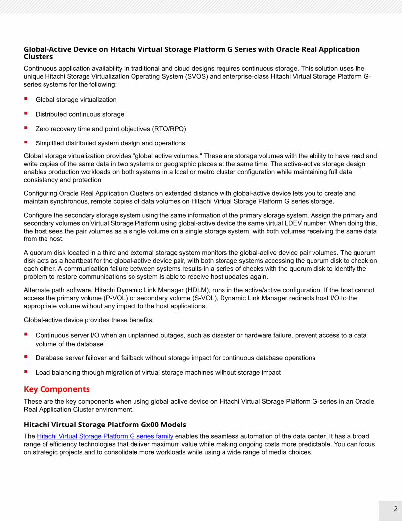
Global-Active Device on Hitachi Virtual Storage Platform G Series with Oracle Real Application ClustersContinuous application availability in traditional and cloud designs requires continuous storage. This solution uses the unique Hitachi Storage Virtualization Operating System (SVOS) and enterprise-class Hitachi Virtual Storage Platform G-series systems for the following:
Global storage virtualization
Distributed continuous storage
Zero recovery time and point objectives (RTO/RPO)
Simplified distributed system design and operations
Global storage virtualization provides "global active volumes." These are storage volumes with the ability to have read and write copies of the same data in two systems or geographic places at the same time. The active-active storage design enables production workloads on both systems in a local or metro cluster configuration while maintaining full data consistency and protection
Configuring Oracle Real Application Clusters on extended distance with global-active device lets you to create and maintain synchronous, remote copies of data volumes on Hitachi Virtual Storage Platform G series storage.
Configure the secondary storage system using the same information of the primary storage system. Assign the primary and secondary volumes on Virtual Storage Platform using global-active device the same virtual LDEV number. When doing this, the host sees the pair volumes as a single volume on a single storage system, with both volumes receiving the same data from the host.
A quorum disk located in a third and external storage system monitors the global-active device pair volumes. The quorum disk acts as a heartbeat for the global-active device pair, with both storage systems accessing the quorum disk to check on each other. A communication failure between systems results in a series of checks with the quorum disk to identify the problem to restore communications so system is able to receive host updates again.
Alternate path software, Hitachi Dynamic Link Manager (HDLM), runs in the active/active configuration. If the host cannot access the primary volume (P-VOL) or secondary volume (S-VOL), Dynamic Link Manager redirects host I/O to the appropriate volume without any impact to the host applications.
Global-active device provides these benefits:
Continuous server I/O when an unplanned outages, such as disaster or hardware failure. prevent access to a data volume of the database
Database server failover and failback without storage impact for continuous database operations
Load balancing through migration of virtual storage machines without storage impact
Key ComponentsThese are the key components when using global-active device on Hitachi Virtual Storage Platform G-series in an Oracle Real Application Cluster environment.
Hitachi Virtual Storage Platform Gx00 ModelsThe Hitachi Virtual Storage Platform G series family enables the seamless automation of the data center. It has a broad range of efficiency technologies that deliver maximum value while making ongoing costs more predictable. You can focus on strategic projects and to consolidate more workloads while using a wide range of media choices.
2
3
The benefits start with Hitachi Storage Virtualization Operating System RF. This includes an all new enhanced software stack that offers up to three times greater performance than our previous midrange models, even as data scales to petabytes.
Virtual Storage Platform G series offers support for containers to accelerate cloud-native application development. Provision storage in seconds, and provide persistent data availability, all the while being orchestrated by industry leading container platforms. Moved these workloads into an enterprise production environment seamlessly, saving money while reducing support and management costs.
Hitachi Storage Virtualization Operating SystemHitachi Storage Virtualization Operating System (SVOS) spans and integrates multiple platforms. It integrates storage system software to provide system element management and advanced storage system functions. Used across multiple platforms, Storage Virtualization Operating System includes storage virtualization, thin provisioning, storage service level controls, dynamic provisioning, and performance instrumentation.
Storage Virtualization Operating System includes standards-based management software on a Hitachi Command Suite (HCS) base. This provides storage configuration and control capabilities for you.
This solution uses Hitachi Dynamic Tiering, a part of Storage Virtualization Operating System, for data mobility. Separately licensed, Dynamic Tiering virtualizes and automates mobility between tiers for maximum performance and efficiency. Instead of manually provisioning space from several storage technologies with different performance and cost characteristics, Dynamic Tiering manages multiple storage tiers as a single entity. It presents a virtual volume with embedded smart tiering to monitor access and move data based on demand.
Dynamic Tiering automatically moves infrequently referenced data to lower cost tiers of storage. This data placement provides higher performance with lower costs. It also provides automatic wide-striping performance optimization.
Storage Virtualization Operating System uses Hitachi Dynamic Provisioning (HDP) to provide wide striping and thin provisioning. Dynamic Provisioning provides one or more wide-striping pools across many RAID groups. Each pool has one or more dynamic provisioning virtual volumes (DP-VOLs) without initially allocating any physical space. Deploying Dynamic Provisioning avoids the routine issue of hot spots that occur on logical devices (LDEVs).
Testing of this environment used multiple dedicated dynamic provisioning pools for different types of Oracle data to avoid intermixing different types of data I/O. This benefited performance during peak database operations.
This features the use of global-active device in Storage Virtual Operating System. This simplified distributed system design and operations. Using global-active device provided the ability to have read/write copies of the same data in two places at the same time.
During testing, the active-active replication design of global-active device implemented cross-mirrored storage volumes between two Hitachi Virtual Storage Platform G600, accepting read/write I/Os on both sides that were continuously updated. If a disk controller failure occurs at one site, the controller at the other site automatically takes over by accepting read/write I/Os.
Using global-active device assured the availability to have an up to date storage volume on the test environment. It enabled production workloads on both systems, while maintaining full data consistency and protection.
Hitachi Dynamic Link ManagerHitachi Dynamic Link Manager, used for SAN multipathing, has configurable load balancing policies. These policies automatically select the path having the least amount of input/output processing through all available paths. This balances the load across all available paths, which optimizes IOPS and response time.
3
4
Oracle DatabaseOracle Database has a multitenant architecture so you can consolidate many databases quickly and manage them as a cloud service. Oracle Database also includes in-memory data processing capabilities for analytical performance. Additional database innovations deliver efficiency, performance, security, and availability. Oracle Database comes in two editions: Enterprise Edition and Standard Edition 2.
Oracle Real Application Clusters (Oracle RAC) is a clustered version of Oracle Database. It is based on a comprehensive high-availability stack that can be used as the foundation of a database cloud system, as well as a shared infrastructure. This ensures high availability, scalability, and agility for any application.
Oracle Automatic Storage Management (Oracle ASM) is a volume manager and a file system for Oracle database files. This supports single-instance Oracle Database and Oracle Real Application Clusters configurations. Oracle ASM is the recommended storage management solution that provides an alternative to conventional volume managers, file systems, and raw devices.
Red Hat Enterprise LinuxRed Hat Enterprise Linux delivers military-grade security, 99.999% uptime, support for business-critical workloads, and so much more. Ultimately, the platform helps you reallocate resources from maintaining the status quo to tackling new challenges.
Best PracticesFollow these best practices when configuring global-active device on Hitachi Virtual Storage Platform G-series in an Oracle Real Application Cluster environment.
Global-active DeviceThese are recommendations when using a global-active device configuration with Hitachi Virtual Storage Platform G series to protect Oracle Database 12c with Oracle Real Application Clusters (RAC) in a two-site environment. For general guidelines on planning a global-active device configuration, refer to the user guide for the global-active device.
Read other documentation about global-active device
Plan System Performance
Remote copy operations can affect the I/O performance of host servers and the primary and secondary storage systems. You can minimize the effects of remote copy operations while you maximize their efficiency and speed by changing your remote connection options and remote replica options. Ask your Hitachi Vantara account team to help you analyze your workload and optimize copy operations.
Using workload data (megabytes per second and IOPS), determine the following for your global-active device system:
Appropriate amount of bandwidth
Number of physical paths
Number of ports
When properly determining and sizing each of these, the data path should operate free of bottlenecks under all workload levels.
When considering disk performance, one recommendation to improve performance is to use Hitachi Accelerated Flash (HAF). This product is integrated with Hitachi Storage Virtualization Operating System (SVOS). Accelerated Flash enables leading, real-applications performance, lower effective cost, and superior consistent response times. The second generation of the flash module drive (FMD DC2) in Accelerated Flash supports concurrent, large I/O enterprise workloads to enable hyper-scale efficiencies. Read more about Hitachi Flash Storage.
4
5
Another way to improve disk performance is to use Hitachi Dynamic Tiering, also a part of Storage Virtualization Operating System. This simplifies storage administration with automatic data placement after you define first, second, or third tier storage within a single virtual volume for optimal data placement. You can make storage tiers using internal or external (virtualized) storage, so the use of Hitachi Dynamic Tiering can lower capital costs. Simplified and unified management of Dynamic Tiering allows lower operational costs while reducing the challenges of placing applications on the appropriate classes of storage. Read more about Hitachi Dynamic Tiering on the Data Mobility pages.
Plan the Quorum Device
Hitachi Vantara recommends keeping your quorum device on a third site. This provides better fault tolerance. However, you can configure your quorum device on the primary site.
Make sure that response time from the external storage system remains adequate. If response time exceeds 100 milliseconds, do what is necessary to reduce it.
Storage subsystems are interconnected using remote connections. This facilitates replication between global active device pairs. When you use multiple remote connections, prepare one quorum disk per remote connection. This helps to avoid the possibility of suspending global-active device pairs due to a single remote connection failure. If one remote connection fails, then other remote connections are available.
This architecture only uses a single quorum disk.
For more information on planning the quorum device, see Global-Active Device User Guide (MK-92RD88072-06). Contact your Hitachi Vantara representative if you need this document.
Plan the Physical Paths
When configuring physical paths to connect the storage systems at the primary and secondary sites, make sure that the paths can handle the maximum data that could be transferred to the primary and secondary volumes under all circumstances.
You must have sufficient bandwidth to handle all data transfers at all workload levels. The amount of required bandwidth depends on the amount of server I/O to the primary volumes.
To identify the required bandwidth, do the following:
1. Collect the write workload data under all workload conditions, including peak write workload.
2. Measure and analyze the data.
Use performance-monitoring software to collect the workload data, such as the following:
Hitachi Tuning Manager
Hitachi Performance Monitor
The tested environment did path configuration using switches. You can also configure paths using channel extenders or direct paths.
Plan Multipathing
Alternate path software on the host runs in the active/active configuration.
While this configuration works well at campus distances, this configuration requires Hitachi Dynamic Link Manager (HDLM) at metro distances for the following:
Support preferred/non-preferred paths
Ensure using the shortest path
5
6
If the host cannot access the primary volume (P-VOL) or secondary volume (S-VOL), Dynamic Link Manager redirects host I/O to the appropriate volume without any impact to the host applications.
It is required to set non-preferred path option on storage system to have the shortest paths for I/O. Dynamic Link Manager identifies such paths as non-owner paths on the hosts. You must set appropriate host group option HMO 78 to set non-preferred paths.
Configure the Database Parameters
Hitachi Vantara recommends setting the MISSCOUNT and DISKTIMEOUT parameters in Oracle, based on your storage configuration.
There were four storage paths per host for the tested environment. This value is used in the example parameter calculations.
Do your parameter value calculations, as follows
MISSCOUNT = [number of paths connected to the voting disk] × 60 seconds
For example, MISSCOUNT = 4 × 60 or 240
DISKTIMEOUT = [number of paths connected to the voting disk] × 60 seconds
For example, DISKTIMEOUT = 4 × 60 or 240
If the number of paths connected to the voting disk are three or less, then there is no need to change the value of DISKTIMEOUT.
To get information on setting the specific configuration for Hitachi Dynamic Link Manager when used with Oracle parameters, refer to the user guide for Dynamic Link Manager for Linux.
Find related documents at global-active device.
Database LayoutBase the storage design for the database layout on the needs on the requirements of the specific application implementation. The design will vary greatly from one implementation to another.
The key components in this best practice guide have the flexibility for use in various deployment scenarios. This provides the right balance between performance and ease of management for a given scenario.
Network ArchitectureThis architecture requires the following separate networks:
Private Network (also called cluster interconnect) — This network must be scalable. In addition, it must meet the low latency needs of the network traffic generated by cache synchronization of Oracle RAC and inter-node communication amongst the nodes in the cluster.
Public Network — This network provides client connections to the applications and Oracle RAC.
Hitachi Vantara recommends using a pair of 10 Gb/s NICs for the cluster interconnect and public network.
Note — If required, you can configure the management network. Configure this with a different subnet other than the public network. With this environment, there is no IP configured for management tasks.
6
7
Observe these points when configuring private and public networks in your Oracle RAC environment:
For each server in the Oracle RAC cluster ware configuration, use at least two identical, high-bandwidth, low-latency NICs for the interconnection.
Use NIC bonding to provide failover and load balancing of interconnections within a server.
Set all NICs to full duplex mode.
Use at least two public NICs for client connections to the application and database.
Use at least two private NICs for the cluster interconnection.
Use redundant Fibre Channel switches for better fault tolerance for a production environment.
ConclusionsThis best practice guide documents for Oracle Database with RAC option using global-active device on Hitachi Virtual Storage Platform Gx00 models. Using Hitachi Storage Virtualization Operating System with global-active device provides an infrastructure with continuous availability that does the following:
Protect your database with global-active device from unplanned outages at data centers to keep database available.
Use global-active device with host-based applications to fail over between a primary site and secondary site Hitachi Virtual Storage Platform Gx00 with no disruption. Hitachi Dynamic Link Manager provides host multipathing with deep storage integration.
Use these recovery best practices for data protection for distances between sites that are from 20 km (12.5 miles) to 100 km (62 miles) apart without unfavorable results.
You can leverage the benefits of synchronous data replication beyond traditional disaster recovery protection to include workload balancing across sites and coordinated site-wide maintenance with no downtime.
7
8
Test EnvironmentThis is the infrastructure used to validate the global-active device environment to protect Oracle Database 12c with the Real Application Clusters option and Oracle Automatic Storage Management.
Table 1, “Key Hardware Components for Site 1,” on page 8
Table 2, “Key Hardware Components for Site 2,” on page 9
Table 3, “Key Hardware Components for the Quorum Site,” on page 9
Table 4, “Key Hardware Components for Pair Management Hosts,” on page 10
Table 5, “Key Software Components,” on page 10
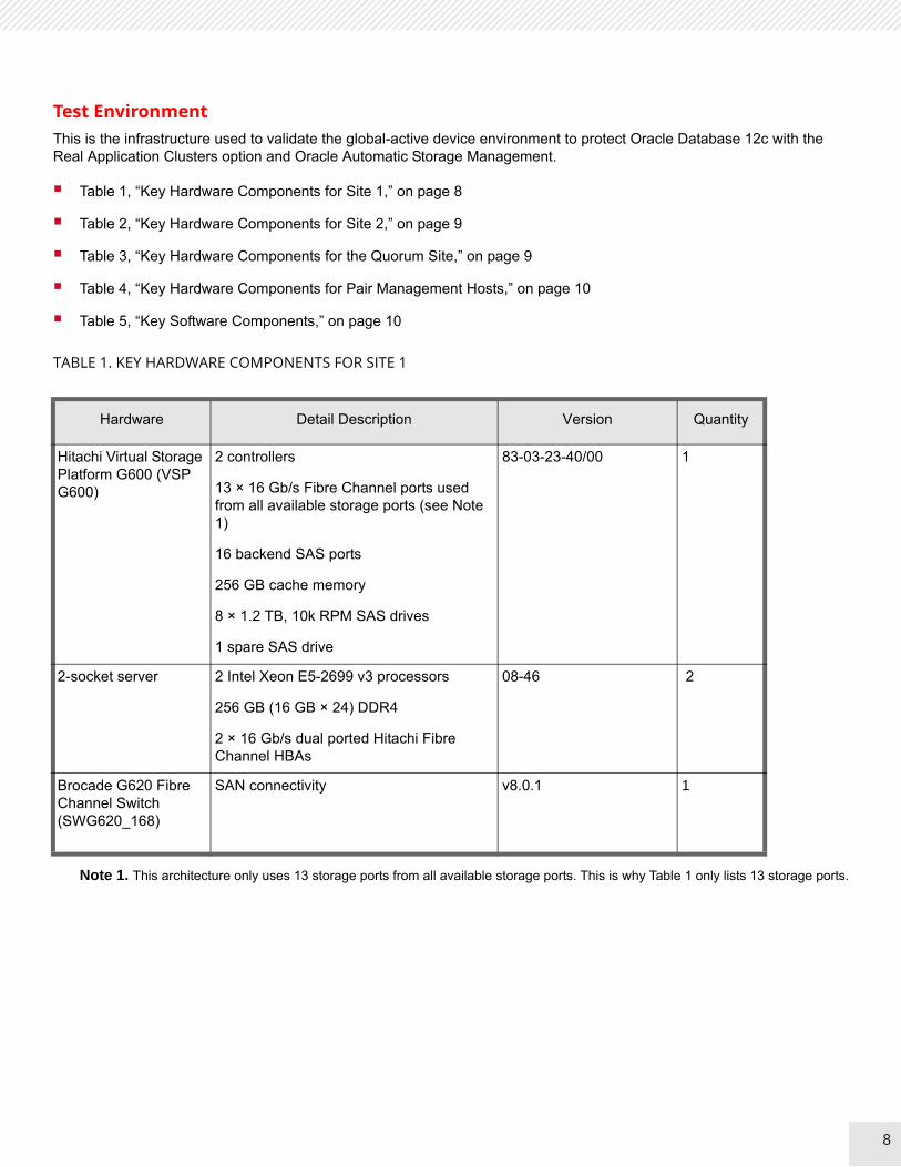
Note 1. This architecture only uses 13 storage ports from all available storage ports. This is why Table 1 only lists 13 storage ports.
TABLE 1. KEY HARDWARE COMPONENTS FOR SITE 1
Hardware Detail Description Version Quantity
Hitachi Virtual Storage Platform G600 (VSP G600)
2 controllers
13 × 16 Gb/s Fibre Channel ports used from all available storage ports (see Note 1)
16 backend SAS ports
256 GB cache memory
8 × 1.2 TB, 10k RPM SAS drives
1 spare SAS drive
83-03-23-40/00 1
2-socket server 2 Intel Xeon E5-2699 v3 processors
256 GB (16 GB × 24) DDR4
2 × 16 Gb/s dual ported Hitachi Fibre Channel HBAs
08-46 2
Brocade G620 Fibre Channel Switch (SWG620_168)
SAN connectivity v8.0.1 1
8
9
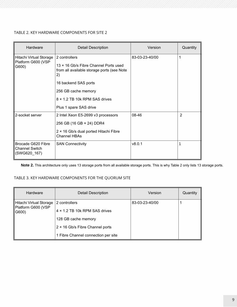
Note 2. This architecture only uses 13 storage ports from all available storage ports. This is why Table 2 only lists 13 storage ports.
TABLE 2. KEY HARDWARE COMPONENTS FOR SITE 2
Hardware Detail Description Version Quantity
Hitachi Virtual Storage Platform G600 (VSP G600)
2 controllers
13 × 16 Gb/s Fibre Channel Ports used from all available storage ports (see Note 2)
16 backend SAS ports
256 GB cache memory
8 × 1.2 TB 10k RPM SAS drives
Plus 1 spare SAS drive
83-03-23-40/00 1
2-socket server 2 Intel Xeon E5-2699 v3 processors
256 GB (16 GB × 24) DDR4
2 × 16 Gb/s dual ported Hitachi Fibre Channel HBAs
08-46 2
Brocade G620 Fibre Channel Switch (SWG620_167)
SAN Connectivity v8.0.1 1
TABLE 3. KEY HARDWARE COMPONENTS FOR THE QUORUM SITE
Hardware Detail Description Version Quantity
Hitachi Virtual Storage Platform G600 (VSP G600)
2 controllers
4 × 1.2 TB 10k RPM SAS drives
128 GB cache memory
2 × 16 Gb/s Fibre Channel ports
1 Fibre Channel connection per site
83-03-23-40/00 1
9
10
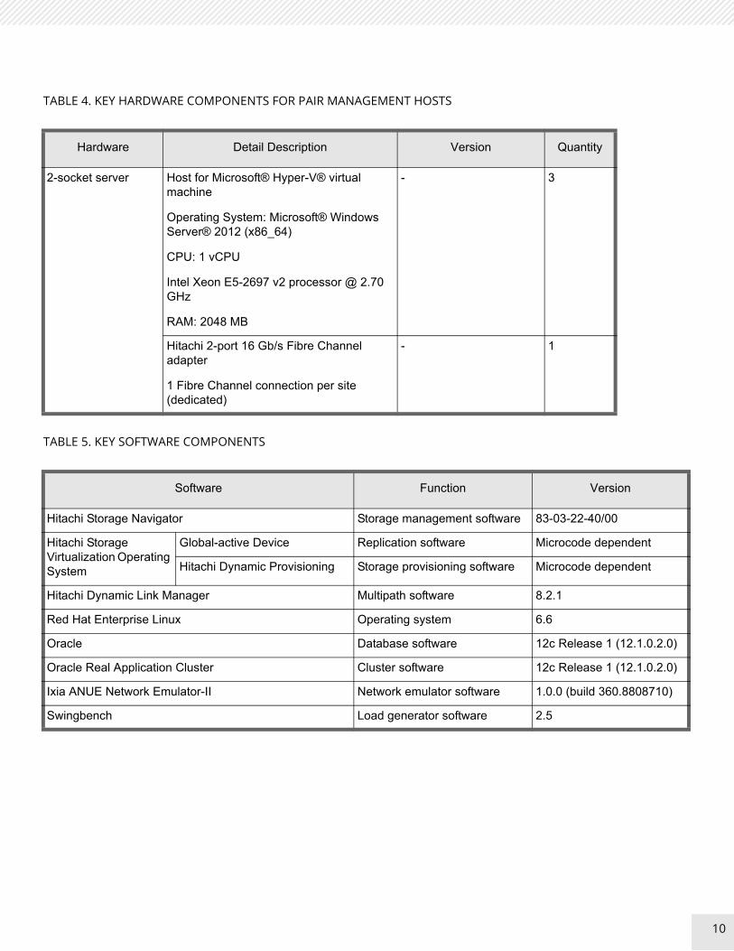
TABLE 4. KEY HARDWARE COMPONENTS FOR PAIR MANAGEMENT HOSTS
Hardware Detail Description Version Quantity
2-socket server Host for Microsoft® Hyper-V® virtual machine
Operating System: Microsoft® Windows Server® 2012 (x86_64)
CPU: 1 vCPU
Intel Xeon E5-2697 v2 processor @ 2.70 GHz
RAM: 2048 MB
- 3
Hitachi 2-port 16 Gb/s Fibre Channel adapter
1 Fibre Channel connection per site (dedicated)
- 1
TABLE 5. KEY SOFTWARE COMPONENTS
Software Function Version
Hitachi Storage Navigator Storage management software 83-03-22-40/00
Hitachi Storage Virtualization Operating System
Global-active Device Replication software Microcode dependent
Hitachi Dynamic Provisioning Storage provisioning software Microcode dependent
Hitachi Dynamic Link Manager Multipath software 8.2.1
Red Hat Enterprise Linux Operating system 6.6
Oracle Database software 12c Release 1 (12.1.0.2.0)
Oracle Real Application Cluster Cluster software 12c Release 1 (12.1.0.2.0)
Ixia ANUE Network Emulator-II Network emulator software 1.0.0 (build 360.8808710)
Swingbench Load generator software 2.5
10
11
Specific infrastructure configuration included the following:
Site 1
Oracle RAC Servers — Two server nodes were configured in an Oracle Real Application Cluster.
One Pair Management Host 1 — This virtual machine managed and monitored global-active device pair operations for the P-VOLs only.
Storage System — This Hitachi Virtual Storage Platform G600 had LDEVs mapped to each port that were presented to the server as LUNs.
SAN Connections — Each 16 Gb/s Fibre Channel HBA port was connected to the storage front-end ports through a switched SAN fabric.
Site 2
Oracle RAC Servers — Two server nodes were configured in an Oracle Real Application Cluster.
One Pair Management Host 2 — This virtual machine managed and monitored global-active device pair operations for the S-VOLs only.
Storage System — This Hitachi Virtual Storage Platform G600 had LDEVs mapped to each port that were presented to the server as LUNs.
SAN Connection — Each 16 Gb/s Fibre Channel HBA port was connected to the storage front-end ports through a switched SAN fabric.
Quorum Site
Storage System — The Hitachi Virtual Storage Platform G600 used as a quorum device had an LDEV mapped to two ports presented as an external volume at site 1 and site 2 to each Virtual Storage Platform G600 on the sites.
SAN Connection — Each 16 Gb/s Fibre Channel HBA port was connected to the storage front-end ports through a switched SAN fabric.
Note — Testing used a separate Hitachi Virtual Storage Platform G600 storage system located at site 1 for the quorum device. When implementing this, you may use any other supported storage system.
Workload application
The workload generation application was Swingbench. One separate virtual machine was used for workload application.
Network Emulator
ANUE Network Emulator II was between the Fibre Channel switches of site 1 and site 2 to provide distance emulation only for the Fibre Channel network
11
12
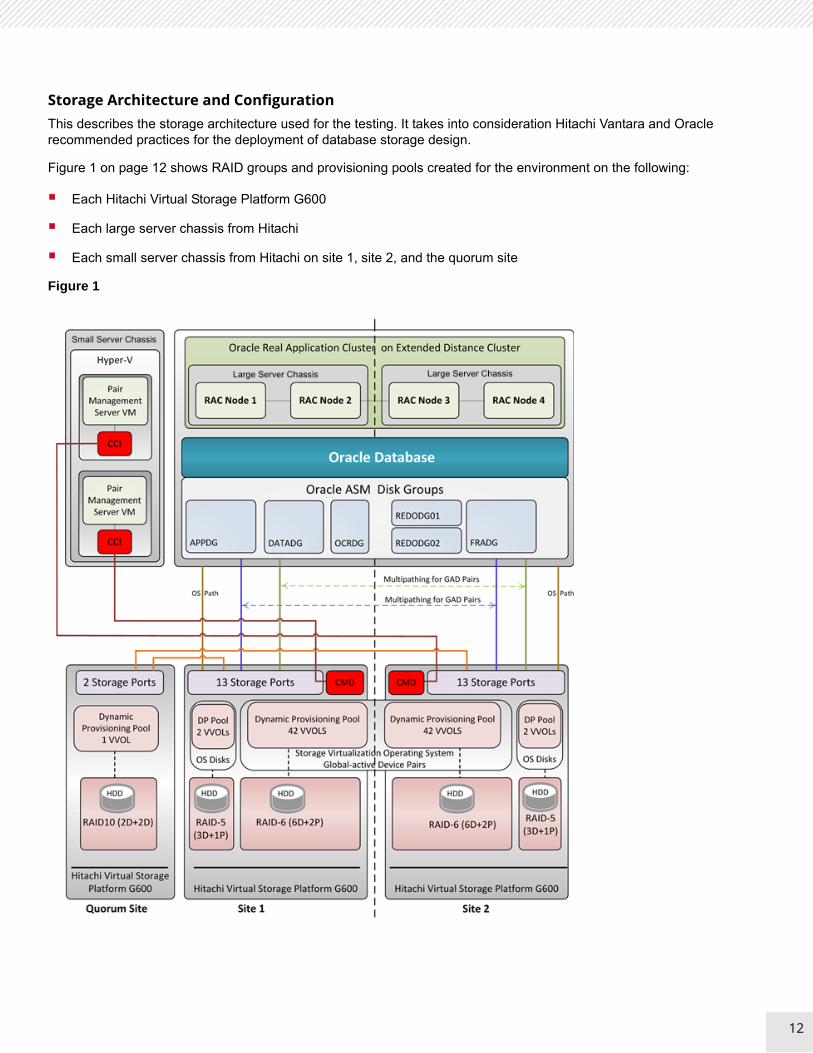
Storage Architecture and ConfigurationThis describes the storage architecture used for the testing. It takes into consideration Hitachi Vantara and Oracle recommended practices for the deployment of database storage design.
Figure 1 on page 12 shows RAID groups and provisioning pools created for the environment on the following:
Each Hitachi Virtual Storage Platform G600
Each large server chassis from Hitachi
Each small server chassis from Hitachi on site 1, site 2, and the quorum site
Figure 1
12
13
Note — Figure 1 is an abstract view of the storage configuration. It does not show the Fibre Channel switch to make other items easier to see.
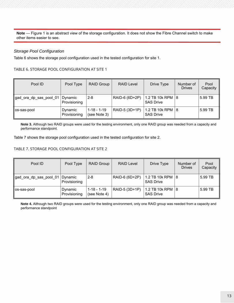
Storage Pool Configuration
Table 6 shows the storage pool configuration used in the tested configuration for site 1.
Note 3. Although two RAID groups were used for the testing environment, only one RAID group was needed from a capacity and performance standpoint.
Table 7 shows the storage pool configuration used in the tested configuration for site 2.
Note 4. Although two RAID groups were used for the testing environment, only one RAID group was needed from a capacity and performance standpoint
TABLE 6. STORAGE POOL CONFIGURATION AT SITE 1
Pool ID Pool Type RAID Group RAID Level Drive Type Number of Drives
Pool Capacity
gad_ora_dp_sas_pool_01 Dynamic Provisioning
2-8 RAID-6 (6D+2P) 1.2 TB 10k RPM SAS Drive
8 5.99 TB
os-sas-pool Dynamic Provisioning
1-18 - 1-19 (see Note 3)
RAID-5 (3D+1P) 1.2 TB 10k RPM SAS Drive
8 5.99 TB
TABLE 7. STORAGE POOL CONFIGURATION AT SITE 2
Pool ID Pool Type RAID Group RAID Level Drive Type Number of Drives
Pool Capacity
gad_ora_dp_sas_pool_01 Dynamic Provisioning
2-8 RAID-6 (6D+2P) 1.2 TB 10k RPM SAS Drive
8 5.99 TB
os-sas-pool Dynamic Provisioning
1-18 - 1-19 (see Note 4)
RAID-5 (3D+1P) 1.2 TB 10k RPM SAS Drive
8 5.99 TB
13
14
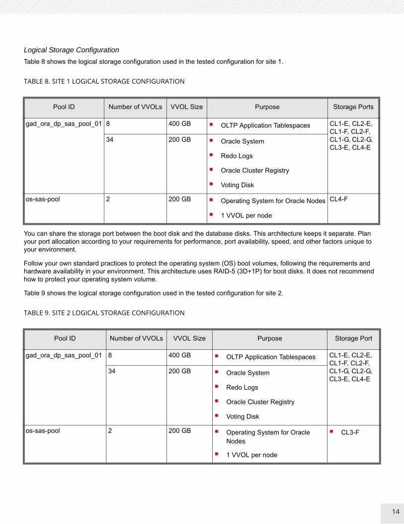
Logical Storage Configuration
Table 8 shows the logical storage configuration used in the tested configuration for site 1.
You can share the storage port between the boot disk and the database disks. This architecture keeps it separate. Plan your port allocation according to your requirements for performance, port availability, speed, and other factors unique to your environment.
Follow your own standard practices to protect the operating system (OS) boot volumes, following the requirements and hardware availability in your environment. This architecture uses RAID-5 (3D+1P) for boot disks. It does not recommend how to protect your operating system volume.
Table 9 shows the logical storage configuration used in the tested configuration for site 2.
TABLE 8. SITE 1 LOGICAL STORAGE CONFIGURATION
Pool ID Number of VVOLs VVOL Size Purpose Storage Ports
gad_ora_dp_sas_pool_01 8 400 GB OLTP Application Tablespaces CL1-E, CL2-E, CL1-F, CL2-F, CL1-G, CL2-G, CL3-E, CL4-E
34 200 GB Oracle System
Redo Logs
Oracle Cluster Registry
Voting Disk
os-sas-pool 2 200 GB Operating System for Oracle Nodes
1 VVOL per node
CL4-F
TABLE 9. SITE 2 LOGICAL STORAGE CONFIGURATION
Pool ID Number of VVOLs VVOL Size Purpose Storage Port
gad_ora_dp_sas_pool_01 8 400 GB OLTP Application Tablespaces CL1-E, CL2-E, CL1-F, CL2-F, CL1-G, CL2-G, CL3-E, CL4-E
34 200 GB Oracle System
Redo Logs
Oracle Cluster Registry
Voting Disk
os-sas-pool 2 200 GB Operating System for Oracle Nodes
1 VVOL per node
CL3-F
14
15
Note – In production environments, some database files may need to be on faster drives for performance reasons. For performance, the recommendation is to have sysaux tablespace (many actions in an active database) and temporary tablespace (sort/order by activities) on flash module drives along with OLTP application tablespaces.
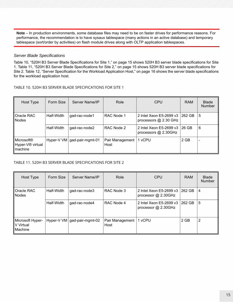
Server Blade Specifications
Table 10, “520H B3 Server Blade Specifications for Site 1,” on page 15 shows 520H B3 server blade specifications for Site 1. Table 11, “520H B3 Server Blade Specifications for Site 2,” on page 15 shows 520H B3 server blade specifications for Site 2. Table 12, “Server Specification for the Workload Application Host,” on page 16 shows the server blade specifications for the workload application host.
TABLE 10. 520H B3 SERVER BLADE SPECIFICATIONS FOR SITE 1
Host Type Form Size Server Name/IP Role CPU RAM Blade Number
Oracle RAC Nodes
Half-Width gad-rac-node1 RAC Node 1 2 Intel Xeon E5-2699 v3 processors @ 2.30 GHz
262 GB 5
Half-Width gad-rac-node2 RAC Node 2 2 Intel Xeon E5-2699 v3 processors @ 2.30GHz
26 GB 6
Microsoft® Hyper-V® virtual machine
Hyper-V VM gad-pair-mgmt-01 Pair Management Host
1 vCPU 2 GB -
TABLE 11. 520H B3 SERVER BLADE SPECIFICATIONS FOR SITE 2
Host Type Form Size Server Name/IP Role CPU RAM Blade Number
Oracle RAC Nodes
Half-Width gad-rac-node3 RAC Node 3 2 Intel Xeon E5-2699 v3 processor @ 2.30GHz
262 GB 4
Half-Width gad-rac-node4 RAC Node 4 2 Intel Xeon E5-2699 v3 processor @ 2.30GHz
262 GB 5
Microsoft Hyper-V Virtual Machine
Hyper-V VM gad-pair-mgmt-02 Pair Management Host
1 vCPU 2 GB 2
15
16
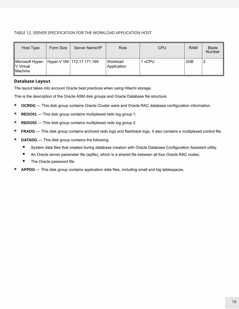
Database LayoutThe layout takes into account Oracle best practices when using Hitachi storage.
This is the description of the Oracle ASM disk groups and Oracle Database file structure:
OCRDG — This disk group contains Oracle Cluster ware and Oracle RAC database configuration information.
REDO01 — This disk group contains multiplexed redo log group 1.
REDO02 — This disk group contains multiplexed redo log group 2.
FRADG — This disk group contains archived redo logs and flashback logs. It also contains a multiplexed control file.
DATADG — This disk group contains the following:
System data files that created during database creation with Oracle Database Configuration Assistant utility.
An Oracle server parameter file (spfile), which is a shared file between all four Oracle RAC nodes.
The Oracle password file
APPDG — This disk group contains application data files, including small and big tablespaces.
TABLE 12. SERVER SPECIFICATION FOR THE WORKLOAD APPLICATION HOST
Host Type Form Size Server Name/IP Role CPU RAM Blade Number
Microsoft Hyper-V Virtual Machine
Hyper-V VM 172.17.171.169 Workload Application
1 vCPU 2GB 2
16
17
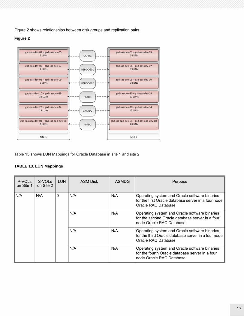
Figure 2 shows relationships between disk groups and replication pairs.
Figure 2
Table 13 shows LUN Mappings for Oracle Database in site 1 and site 2
TABLE 13. LUN Mappings
P-VOLs on Site 1
S-VOLs on Site 2
LUN ASM Disk ASMDG Purpose
N/A N/A 0 N/A N/A Operating system and Oracle software binaries for the first Oracle database server in a four node Oracle RAC Database
N/A N/A Operating system and Oracle software binaries for the second Oracle database server in a four node Oracle RAC Database
N/A N/A Operating system and Oracle software binaries for the third Oracle database server in a four node Oracle RAC Database
N/A N/A Operating system and Oracle software binaries for the fourth Oracle database server in a four node Oracle RAC Database
17

18
00:00:3B
00:00:3C
00:00:3D
00:00:3E
00:00:3F
00:00:03
00:00:0A
00:00:0B
00:00:0C
00:00:0D
0 – 4 /dev/asmdisks/gad-sas-dev-01 to /dev/asmdisks/gad-sas-dev-05
OCRDG Oracle Cluster Registry and Voting Disk
00:00:40
00:00:41
00:00:0E
00:00:0F
5 – 6 /dev/asmdisks/gad-sas-dev-06 to /dev/asmdisks/gad-sas-dev-07
REDODG01 Online REDO log group and control file
00:00:42
00:00:43
00:00:10
00:00:11
7 – 8 /dev/asmdisks/gad-sas-dev-08 to /dev/asmdisks/gad-sas-dev-09
REDODG02 Online REDO log group and control file
00:00:44
00:00:45
00:00:46
00:00:47
00:00:48
00:00:49
00:00:4A
00:00:4B
00:00:4C
00:00:4D
00:00:12
00:00:13
00:00:14
00:00:15
00:00:16
00:00:17
00:00:18
00:00:19
00:00:1A
00:00:1B
9 – 18
/dev/asmdisks/gad-sas-dev-10 to /dev/asmdisks/gad-sas-dev-19
DATADG System table spaces and parameter and password files
Sys
Sysaux
Undo
temp
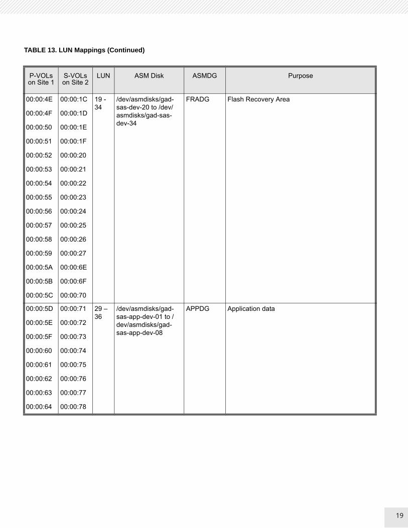
TABLE 13. LUN Mappings (Continued)
P-VOLs on Site 1
S-VOLs on Site 2
LUN ASM Disk ASMDG Purpose
18
19
00:00:4E
00:00:4F
00:00:50
00:00:51
00:00:52
00:00:53
00:00:54
00:00:55
00:00:56
00:00:57
00:00:58
00:00:59
00:00:5A
00:00:5B
00:00:5C
00:00:1C
00:00:1D
00:00:1E
00:00:1F
00:00:20
00:00:21
00:00:22
00:00:23
00:00:24
00:00:25
00:00:26
00:00:27
00:00:6E
00:00:6F
00:00:70
19 - 34
/dev/asmdisks/gad-sas-dev-20 to /dev/asmdisks/gad-sas-dev-34
FRADG Flash Recovery Area
00:00:5D
00:00:5E
00:00:5F
00:00:60
00:00:61
00:00:62
00:00:63
00:00:64
00:00:71
00:00:72
00:00:73
00:00:74
00:00:75
00:00:76
00:00:77
00:00:78
29 – 36
/dev/asmdisks/gad-sas-app-dev-01 to /dev/asmdisks/gad-sas-app-dev-08
APPDG Application data
TABLE 13. LUN Mappings (Continued)
P-VOLs on Site 1
S-VOLs on Site 2
LUN ASM Disk ASMDG Purpose
19
20
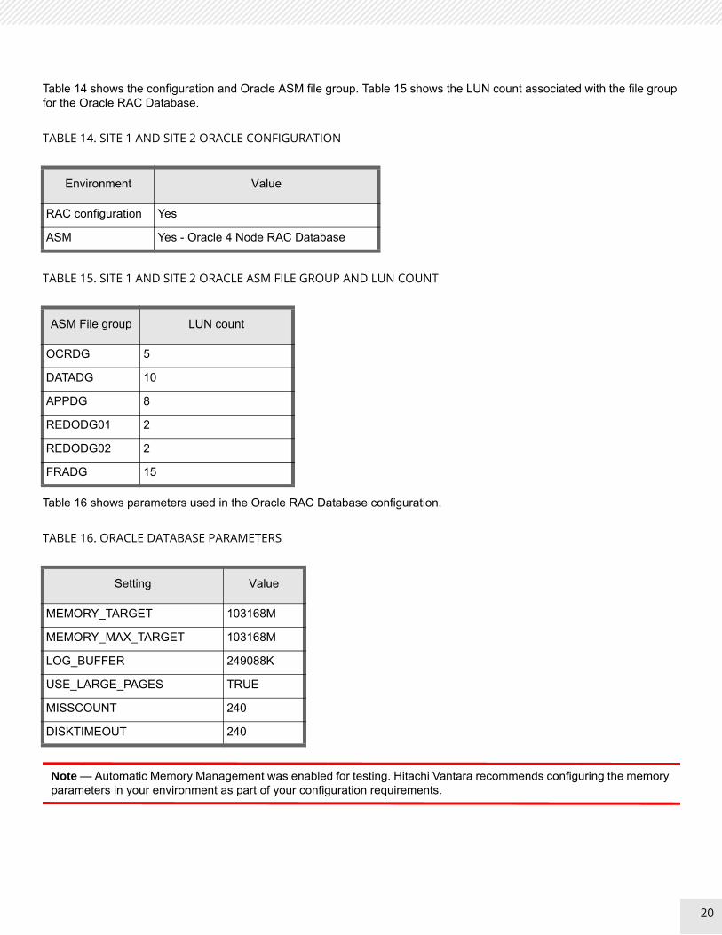
Table 14 shows the configuration and Oracle ASM file group. Table 15 shows the LUN count associated with the file group for the Oracle RAC Database.
Table 16 shows parameters used in the Oracle RAC Database configuration.
Note — Automatic Memory Management was enabled for testing. Hitachi Vantara recommends configuring the memory parameters in your environment as part of your configuration requirements.
TABLE 14. SITE 1 AND SITE 2 ORACLE CONFIGURATION
Environment Value
RAC configuration Yes
ASM Yes - Oracle 4 Node RAC Database
TABLE 15. SITE 1 AND SITE 2 ORACLE ASM FILE GROUP AND LUN COUNT
ASM File group LUN count
OCRDG 5
DATADG 10
APPDG 8
REDODG01 2
REDODG02 2
FRADG 15
TABLE 16. ORACLE DATABASE PARAMETERS
Setting Value
MEMORY_TARGET 103168M
MEMORY_MAX_TARGET 103168M
LOG_BUFFER 249088K
USE_LARGE_PAGES TRUE
MISSCOUNT 240
DISKTIMEOUT 240
20
21
SAN ArchitectureThis describes the SAN architecture used when testing global-active device on Hitachi Virtual Storage Platform G-series in an Oracle Real Application Cluster environment.
Fibre Channel Connections
The provisioned LDEVs are mapped to multiple ports on Hitachi Virtual Storage Platform G600 (VSP G600). These LDEV port assignments provide multiple paths to the storage system from the host for high availability.
On the Site 1 (local) and the Site 2 (remote) VSP G600, four (per site) SAN switch connections are being used for the respective local Oracle host HBA to storage port.
On the Site 1 (local) and the Site 2 (remote) VSP G600, four (per site) storage ports are being used for the respective remote Oracle host HBA to storage port through SAN switches.
Two (non-dedicated) storage ports, one from each VSP G600, are being used for pair management hosts.
Two (non-dedicated) storage ports, one from each VSP G600, are being used for Quorum connections.
Two ports are used as replication ports in between site1 VSP G600 and site 2 VSP G600
Below is the storage location site wise
ASE_42_23 - Site 1 VSP G600
ASE_42_33 - Site 2 VSP G600
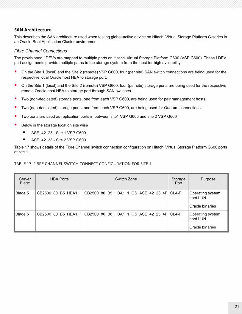
Table 17 shows details of the Fibre Channel switch connection configuration on Hitachi Virtual Storage Platform G600 ports at site 1.
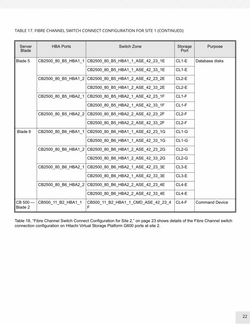
TABLE 17. FIBRE CHANNEL SWITCH CONNECT CONFIGURATION FOR SITE 1
Server Blade
HBA Ports Switch Zone Storage Port
Purpose
Blade 5 CB2500_80_B5_HBA1_1 CB2500_80_B5_HBA1_1_OS_ASE_42_23_4F CL4-F Operating system boot LUN
Oracle binaries
Blade 6 CB2500_80_B6_HBA1_1 CB2500_80_B6_HBA1_1_OS_ASE_42_23_4F CL4-F Operating system boot LUN
Oracle binaries
21
22
Table 18, “Fibre Channel Switch Connect Configuration for Site 2,” on page 23 shows details of the Fibre Channel switch connection configuration on Hitachi Virtual Storage Platform G600 ports at site 2.
Blade 5 CB2500_80_B5_HBA1_1 CB2500_80_B5_HBA1_1_ASE_42_23_1E CL1-E Database disks
CB2500_80_B5_HBA1_1_ASE_42_33_1E CL1-E
CB2500_80_B5_HBA1_2 CB2500_80_B5_HBA1_2_ASE_42_23_2E CL2-E
CB2500_80_B5_HBA1_2_ASE_42_33_2E CL2-E
CB2500_80_B5_HBA2_1 CB2500_80_B5_HBA2_1_ASE_42_23_1F CL1-F
CB2500_80_B5_HBA2_1_ASE_42_33_1F CL1-F
CB2500_80_B5_HBA2_2 CB2500_80_B5_HBA2_2_ASE_42_23_2F CL2-F
CB2500_80_B5_HBA2_2_ASE_42_33_2F CL2-F
Blade 6 CB2500_80_B6_HBA1_1 CB2500_80_B6_HBA1_1_ASE_42_23_1G CL1-G
CB2500_80_B6_HBA1_1_ASE_42_33_1G CL1-G
CB2500_80_B6_HBA1_2 CB2500_80_B6_HBA1_2_ASE_42_23_2G CL2-G
CB2500_80_B6_HBA1_2_ASE_42_33_2G CL2-G
CB2500_80_B6_HBA2_1 CB2500_80_B6_HBA2_1_ASE_42_23_3E CL3-E
CB2500_80_B6_HBA2_1_ASE_42_33_3E CL3-E
CB2500_80_B6_HBA2_2 CB2500_80_B6_HBA2_2_ASE_42_23_4E CL4-E
CB2500_80_B6_HBA2_2_ASE_42_33_4E CL4-E
CB 500 — Blade 2
CB500_11_B2_HBA1_1 CB500_11_B2_HBA1_1_CMD_ASE_42_23_4F
CL4-F Command Device
TABLE 17. FIBRE CHANNEL SWITCH CONNECT CONFIGURATION FOR SITE 1 (CONTINUED)
Server Blade
HBA Ports Switch Zone Storage Port
Purpose
22
23
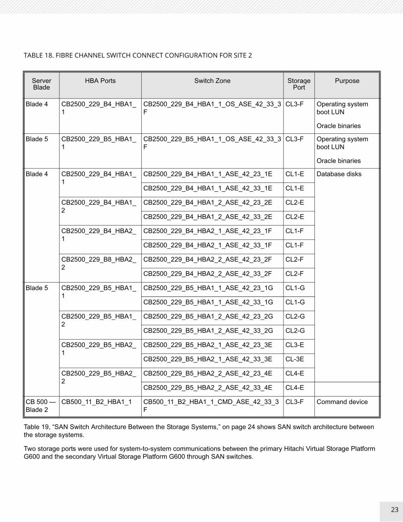
Table 19, “SAN Switch Architecture Between the Storage Systems,” on page 24 shows SAN switch architecture between the storage systems.
Two storage ports were used for system-to-system communications between the primary Hitachi Virtual Storage Platform G600 and the secondary Virtual Storage Platform G600 through SAN switches.
TABLE 18. FIBRE CHANNEL SWITCH CONNECT CONFIGURATION FOR SITE 2
Server Blade
HBA Ports Switch Zone Storage Port
Purpose
Blade 4 CB2500_229_B4_HBA1_1
CB2500_229_B4_HBA1_1_OS_ASE_42_33_3F
CL3-F Operating system boot LUN
Oracle binaries
Blade 5 CB2500_229_B5_HBA1_1
CB2500_229_B5_HBA1_1_OS_ASE_42_33_3F
CL3-F Operating system boot LUN
Oracle binaries
Blade 4 CB2500_229_B4_HBA1_1
CB2500_229_B4_HBA1_1_ASE_42_23_1E CL1-E Database disks
CB2500_229_B4_HBA1_1_ASE_42_33_1E CL1-E
CB2500_229_B4_HBA1_2
CB2500_229_B4_HBA1_2_ASE_42_23_2E CL2-E
CB2500_229_B4_HBA1_2_ASE_42_33_2E CL2-E
CB2500_229_B4_HBA2_1
CB2500_229_B4_HBA2_1_ASE_42_23_1F CL1-F
CB2500_229_B4_HBA2_1_ASE_42_33_1F CL1-F
CB2500_229_B8_HBA2_2
CB2500_229_B4_HBA2_2_ASE_42_23_2F CL2-F
CB2500_229_B4_HBA2_2_ASE_42_33_2F CL2-F
Blade 5 CB2500_229_B5_HBA1_1
CB2500_229_B5_HBA1_1_ASE_42_23_1G CL1-G
CB2500_229_B5_HBA1_1_ASE_42_33_1G CL1-G
CB2500_229_B5_HBA1_2
CB2500_229_B5_HBA1_2_ASE_42_23_2G CL2-G
CB2500_229_B5_HBA1_2_ASE_42_33_2G CL2-G
CB2500_229_B5_HBA2_1
CB2500_229_B5_HBA2_1_ASE_42_23_3E CL3-E
CB2500_229_B5_HBA2_1_ASE_42_33_3E CL-3E
CB2500_229_B5_HBA2_2
CB2500_229_B5_HBA2_2_ASE_42_23_4E CL4-E
CB2500_229_B5_HBA2_2_ASE_42_33_4E CL4-E
CB 500 — Blade 2
CB500_11_B2_HBA1_1 CB500_11_B2_HBA1_1_CMD_ASE_42_33_3F
CL3-F Command device
23
24
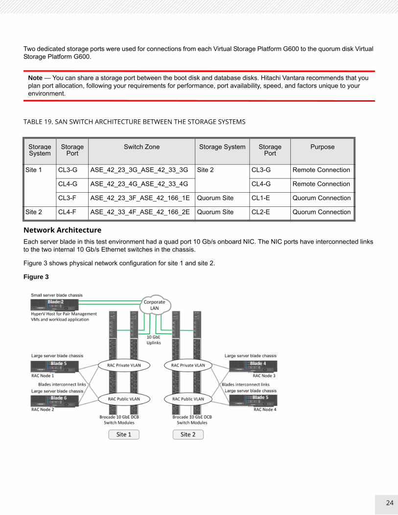
Two dedicated storage ports were used for connections from each Virtual Storage Platform G600 to the quorum disk Virtual Storage Platform G600.
Note — You can share a storage port between the boot disk and database disks. Hitachi Vantara recommends that you plan port allocation, following your requirements for performance, port availability, speed, and factors unique to your environment.
Network ArchitectureEach server blade in this test environment had a quad port 10 Gb/s onboard NIC. The NIC ports have interconnected links to the two internal 10 Gb/s Ethernet switches in the chassis.
Figure 3 shows physical network configuration for site 1 and site 2.
Figure 3
TABLE 19. SAN SWITCH ARCHITECTURE BETWEEN THE STORAGE SYSTEMS
Storage System
Storage Port
Switch Zone Storage System Storage Port
Purpose
Site 1 CL3-G ASE_42_23_3G_ASE_42_33_3G Site 2 CL3-G Remote Connection
CL4-G ASE_42_23_4G_ASE_42_33_4G CL4-G Remote Connection
CL3-F ASE_42_23_3F_ASE_42_166_1E Quorum Site CL1-E Quorum Connection
Site 2 CL4-F ASE_42_33_4F_ASE_42_166_2E Quorum Site CL2-E Quorum Connection
24
25
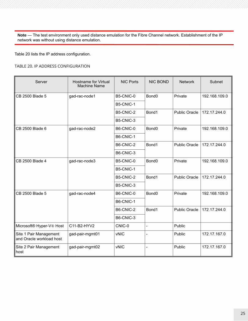
Note — The test environment only used distance emulation for the Fibre Channel network. Establishment of the IP network was without using distance emulation.
Table 20 lists the IP address configuration.
TABLE 20. IP ADDRESS CONFIGURATION
Server Hostname for Virtual Machine Name
NIC Ports NIC BOND Network Subnet
CB 2500 Blade 5 gad-rac-node1 B5-CNIC-0 Bond0 Private 192.168.109.0
B5-CNIC-1
B5-CNIC-2 Bond1 Public Oracle 172.17.244.0
B5-CNIC-3
CB 2500 Blade 6 gad-rac-node2 B6-CNIC-0 Bond0 Private 192.168.109.0
B6-CNIC-1
B6-CNIC-2 Bond1 Public Oracle 172.17.244.0
B6-CNIC-3
CB 2500 Blade 4 gad-rac-node3 B5-CNIC-0 Bond0 Private 192.168.109.0
B5-CNIC-1
B5-CNIC-2 Bond1 Public Oracle 172.17.244.0
B5-CNIC-3
CB 2500 Blade 5 gad-rac-node4 B6-CNIC-0 Bond0 Private 192.168.109.0
B6-CNIC-1
B6-CNIC-2 Bond1 Public Oracle 172.17.244.0
B6-CNIC-3
Microsoft® Hyper-V® Host C11-B2-HYV2 CNIC-0 - Public
Site 1 Pair Management and Oracle workload host
gad-pair-mgmt01 vNIC - Public 172.17.167.0
Site 2 Pair Management host
gad-pair-mgmt02 vNIC - Public 172.17.167.0
25
26
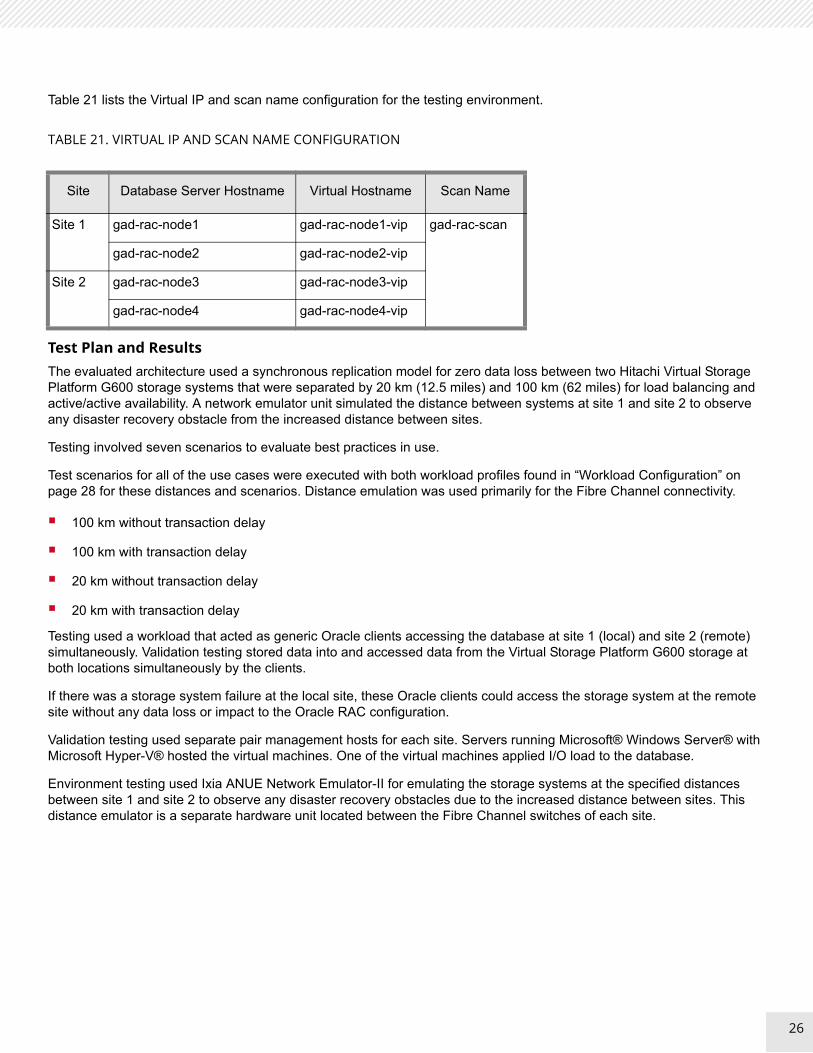
Table 21 lists the Virtual IP and scan name configuration for the testing environment.
Test Plan and ResultsThe evaluated architecture used a synchronous replication model for zero data loss between two Hitachi Virtual Storage Platform G600 storage systems that were separated by 20 km (12.5 miles) and 100 km (62 miles) for load balancing and active/active availability. A network emulator unit simulated the distance between systems at site 1 and site 2 to observe any disaster recovery obstacle from the increased distance between sites.
Testing involved seven scenarios to evaluate best practices in use.
Test scenarios for all of the use cases were executed with both workload profiles found in “Workload Configuration” on page 28 for these distances and scenarios. Distance emulation was used primarily for the Fibre Channel connectivity.
100 km without transaction delay
100 km with transaction delay
20 km without transaction delay
20 km with transaction delay
Testing used a workload that acted as generic Oracle clients accessing the database at site 1 (local) and site 2 (remote) simultaneously. Validation testing stored data into and accessed data from the Virtual Storage Platform G600 storage at both locations simultaneously by the clients.
If there was a storage system failure at the local site, these Oracle clients could access the storage system at the remote site without any data loss or impact to the Oracle RAC configuration.
Validation testing used separate pair management hosts for each site. Servers running Microsoft® Windows Server® with Microsoft Hyper-V® hosted the virtual machines. One of the virtual machines applied I/O load to the database.
Environment testing used Ixia ANUE Network Emulator-II for emulating the storage systems at the specified distances between site 1 and site 2 to observe any disaster recovery obstacles due to the increased distance between sites. This distance emulator is a separate hardware unit located between the Fibre Channel switches of each site.
TABLE 21. VIRTUAL IP AND SCAN NAME CONFIGURATION
Site Database Server Hostname Virtual Hostname Scan Name
Site 1 gad-rac-node1 gad-rac-node1-vip gad-rac-scan
gad-rac-node2 gad-rac-node2-vip
Site 2 gad-rac-node3 gad-rac-node3-vip
gad-rac-node4 gad-rac-node4-vip
26
27
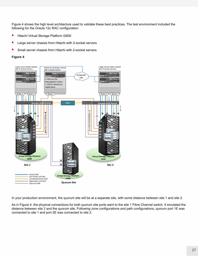
Figure 4 shows the high level architecture used to validate these best practices. The test environment included the following for the Oracle 12c RAC configuration:
Hitachi Virtual Storage Platform G600
Large server chassis from Hitachi with 2-socket servers
Small server chassis from Hitachi with 2-socket servers
Figure 4
In your production environment, the quorum site will be at a separate site, with some distance between site 1 and site 2.
As in Figure 4, the physical connections for both quorum site ports went to the site 1 Fibre Channel switch. It emulated the distance between site 2 and the quorum site. Following zone configurations and path configurations, quorum port 1E was connected to site 1 and port 2E was connected to site 2.
27
28
Workload Configuration
Testing included test iterations that ran simulated and synthetic workloads using Swingbench. This simulated the workloads for Hitachi Virtual Storage Platform G600 with Storage Virtualization Operating System to test the global-active device.
These were the planned profiles:
Order Entry profile configured with no delay between transactions.
Order Entry profile configured with minimum delay between transactions of 850 msec and maximum delay between transactions of 1050 msec.
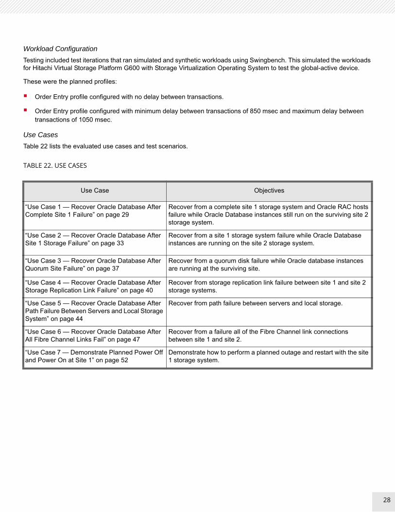
Use Cases
Table 22 lists the evaluated use cases and test scenarios.
TABLE 22. USE CASES
Use Case Objectives
“Use Case 1 — Recover Oracle Database After Complete Site 1 Failure” on page 29
Recover from a complete site 1 storage system and Oracle RAC hosts failure while Oracle Database instances still run on the surviving site 2 storage system.
“Use Case 2 — Recover Oracle Database After Site 1 Storage Failure” on page 33
Recover from a site 1 storage system failure while Oracle Database instances are running on the site 2 storage system.
“Use Case 3 — Recover Oracle Database After Quorum Site Failure” on page 37
Recover from a quorum disk failure while Oracle database instances are running at the surviving site.
“Use Case 4 — Recover Oracle Database After Storage Replication Link Failure” on page 40
Recover from storage replication link failure between site 1 and site 2 storage systems.
“Use Case 5 — Recover Oracle Database After Path Failure Between Servers and Local Storage System” on page 44
Recover from path failure between servers and local storage.
“Use Case 6 — Recover Oracle Database After All Fibre Channel Links Fail” on page 47
Recover from a failure all of the Fibre Channel link connections between site 1 and site 2.
“Use Case 7 — Demonstrate Planned Power Off and Power On at Site 1” on page 52
Demonstrate how to perform a planned outage and restart with the site 1 storage system.
28
29
Use Case 1 — Recover Oracle Database After Complete Site 1 Failure
This was the objective for Use Case 1:
Recover from a complete site 1 storage system and Oracle RAC hosts failure while Oracle Database instances still run on the surviving site 2 storage system.
This was the procedure used to evaluate Use Case 1:
1. System Status Checks
(1) Verify that all paths are online for all Oracle RAC nodes.
Command example: dlnkmgr view -path
(2) Verify that all disk pairs are in PAIR status at both the sites.
Command example: pairdisplay -g GAD_RG -fcxe
(3) Verify that database resource is open and stable.
Command example: crsctl stat res -t
(4) Start Swingbench workload with number of users configured as 20.
2. Simulate Failure
(1) At site 1, disable Fibre Channel switch ports in this order that are used for the following:
i. Remote connections (replication links)
ii. Quorum connections
iii. Data disks
iv. Command device
(2) After disabling replication links, if the P-VOL status is L/L (I/O mode is Local), restore using the Recovery Procedure in “Use Case 3 — Recover Oracle Database After Quorum Site Failure” on page 37.
(3) If P-VOL status is B/B (I/O mode is Block), then execute the following.
Shut down both of the Oracle RAC hosts at site 1.
During testing, this was executed, as the P-VOL status was B/B.
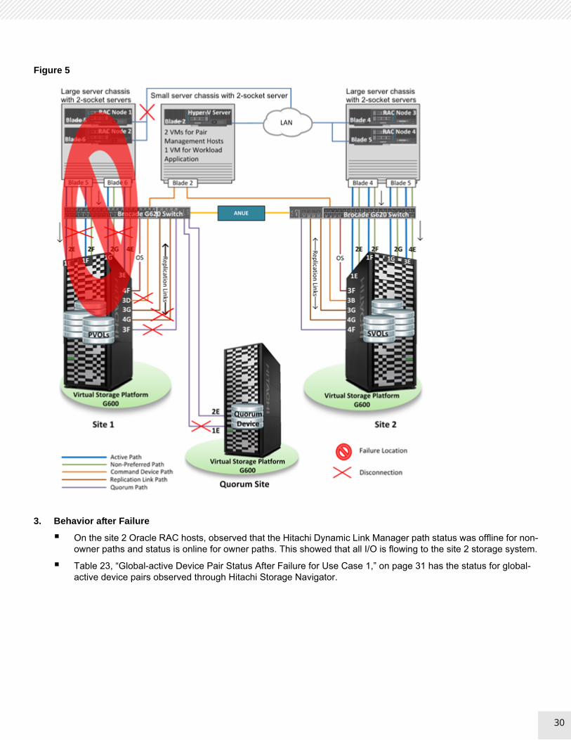
Figure 5 on page 30 shows a complete failure at site 1.
29
30
Figure 5
3. Behavior after Failure
On the site 2 Oracle RAC hosts, observed that the Hitachi Dynamic Link Manager path status was offline for non-owner paths and status is online for owner paths. This showed that all I/O is flowing to the site 2 storage system.
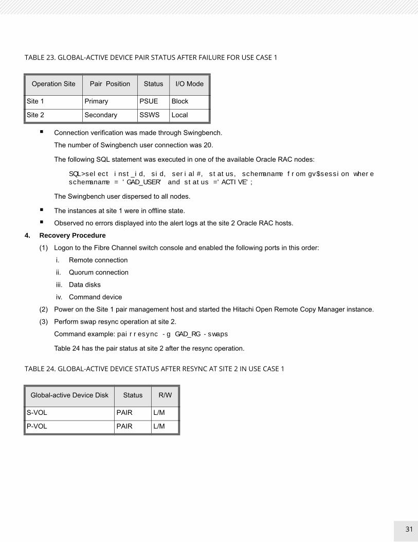
Table 23, “Global-active Device Pair Status After Failure for Use Case 1,” on page 31 has the status for global-active device pairs observed through Hitachi Storage Navigator.
30
31
Connection verification was made through Swingbench.
The number of Swingbench user connection was 20.
The following SQL statement was executed in one of the available Oracle RAC nodes:
SQL>select inst_id, sid, serial#, status, schemaname from gv$session where schemaname = 'GAD_USER' and status ='ACTIVE';
The Swingbench user dispersed to all nodes.
The instances at site 1 were in offline state.
Observed no errors displayed into the alert logs at the site 2 Oracle RAC hosts.
4. Recovery Procedure
(1) Logon to the Fibre Channel switch console and enabled the following ports in this order:
i. Remote connection
ii. Quorum connection
iii. Data disks
iv. Command device
(2) Power on the Site 1 pair management host and started the Hitachi Open Remote Copy Manager instance.
(3) Perform swap resync operation at site 2.
Command example: pairresync -g GAD_RG -swaps
Table 24 has the pair status at site 2 after the resync operation.
TABLE 23. GLOBAL-ACTIVE DEVICE PAIR STATUS AFTER FAILURE FOR USE CASE 1
Operation Site Pair Position Status I/O Mode
Site 1 Primary PSUE Block
Site 2 Secondary SSWS Local
TABLE 24. GLOBAL-ACTIVE DEVICE STATUS AFTER RESYNC AT SITE 2 IN USE CASE 1
Global-active Device Disk Status R/W
S-VOL PAIR L/M
P-VOL PAIR L/M
31
32
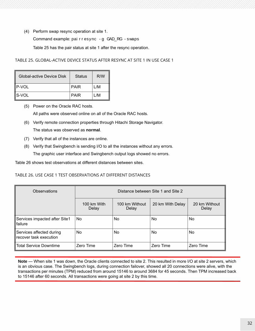
(4) Perform swap resync operation at site 1.
Command example: pairresync -g GAD_RG -swaps
Table 25 has the pair status at site 1 after the resync operation.
(5) Power on the Oracle RAC hosts.
All paths were observed online on all of the Oracle RAC hosts.
(6) Verify remote connection properties through Hitachi Storage Navigator.
The status was observed as normal.
(7) Verify that all of the instances are online.
(8) Verify that Swingbench is sending I/O to all the instances without any errors.
The graphic user interface and Swingbench output logs showed no errors.
Table 26 shows test observations at different distances between sites.
Note — When site 1 was down, the Oracle clients connected to site 2. This resulted in more I/O at site 2 servers, which is an obvious case. The Swingbench logs, during connection failover, showed all 20 connections were alive, with the transactions per minutes (TPM) reduced from around 15146 to around 3684 for 45 seconds. Then TPM increased back to 15146 after 60 seconds. All transactions were going at site 2 by this time.
TABLE 25. GLOBAL-ACTIVE DEVICE STATUS AFTER RESYNC AT SITE 1 IN USE CASE 1
Global-active Device Disk Status R/W
P-VOL PAIR L/M
S-VOL PAIR L/M
TABLE 26. USE CASE 1 TEST OBSERVATIONS AT DIFFERENT DISTANCES
Observations Distance between Site 1 and Site 2
100 km With Delay
100 km Without Delay
20 km With Delay 20 km Without Delay
Services impacted after Site1 failure
No No No No
Services affected during recover task execution
No No No No
Total Service Downtime Zero Time Zero Time Zero Time Zero Time
32
33
Use Case 2 — Recover Oracle Database After Site 1 Storage Failure
This was the objective for Use Case 2:
Recover from a site 1 storage system failure while Oracle Database instances are running on the site 2 storage system.
This was the procedure used to evaluate Use Case 2:
1. System Status Checks
(1) Verify that all paths are online for all Oracle RAC nodes.
Command example: dlnkmgr view -path
(2) Verify that all disk pairs are in PAIR status at both the sites.
Command example: pairdisplay -g GAD_RG -fcxe
(3) Verify that database resource is open and stable.
Command example: crsctl stat res -t
(4) Start Swingbench workload with number of users configured as 20.
2. Simulate Failure
(1) At site 1, disable the Fibre Channel switch ports used for remote connections.
(2) If the P-VOL status is L/L (I/O mode is Local), restore using the Recovery Procedure in Use Case 3 — Recover Oracle Database After Quorum Site Failure..
(3) If P-VOL status is B/B (I/O mode is Block), then execute the following.
At site 1, disable the Fibre Channel switch ports used for data disks.
During testing, this was executed, as the P-VOL status was B/B.
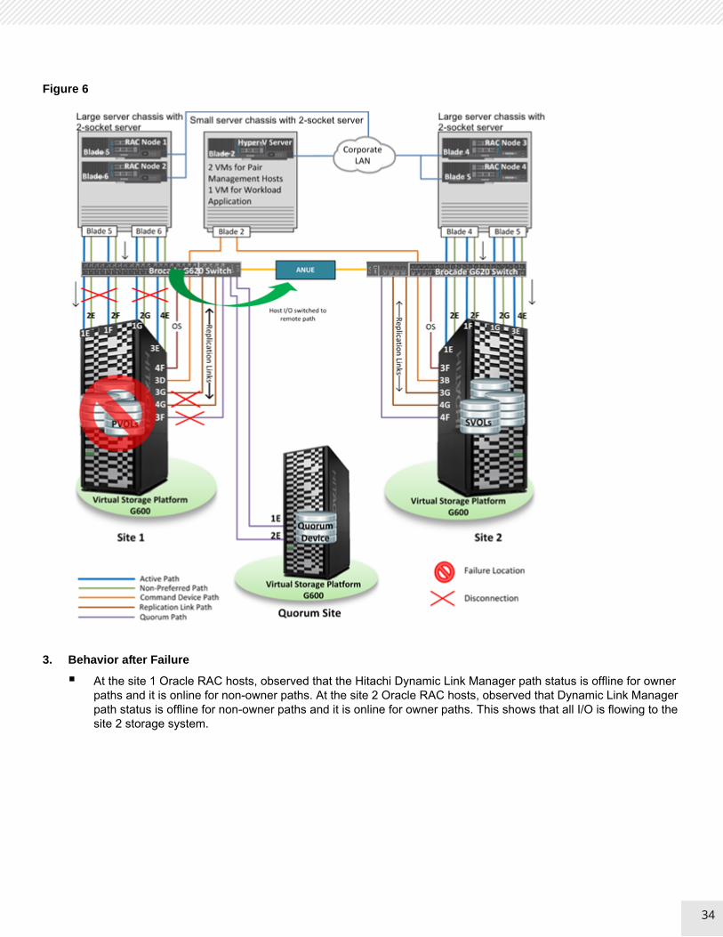
Figure 6 on page 34 shows a storage failure at site 1.
33
34
Figure 6
3. Behavior after Failure
At the site 1 Oracle RAC hosts, observed that the Hitachi Dynamic Link Manager path status is offline for owner paths and it is online for non-owner paths. At the site 2 Oracle RAC hosts, observed that Dynamic Link Manager path status is offline for non-owner paths and it is online for owner paths. This shows that all I/O is flowing to the site 2 storage system.
34
35
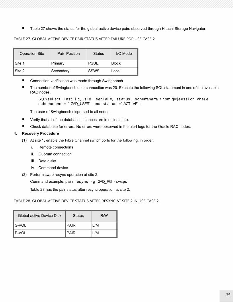
Table 27 shows the status for the global-active device pairs observed through Hitachi Storage Navigator.
Connection verification was made through Swingbench.
The number of Swingbench user connection was 20. Execute the following SQL statement in one of the available RAC nodes.
SQL>select inst_id, sid, serial#, status, schemaname from gv$session where schemaname = 'GAD_USER' and status ='ACTIVE';
The user of Swingbench dispersed to all nodes.
Verify that all of the database instances are in online state.
Check database for errors. No errors were observed in the alert logs for the Oracle RAC nodes.
4. Recovery Procedure
(1) At site 1, enable the Fibre Channel switch ports for the following, in order:
i. Remote connections
ii. Quorum connection
iii. Data disks
iv. Command device
(2) Perform swap resync operation at site 2.
Command example: pairresync -g GAD_RG -swaps
Table 28 has the pair status after resync operation at site 2.
TABLE 27. GLOBAL-ACTIVE DEVICE PAIR STATUS AFTER FAILURE FOR USE CASE 2
Operation Site Pair Position Status I/O Mode
Site 1 Primary PSUE Block
Site 2 Secondary SSWS Local
TABLE 28. GLOBAL-ACTIVE DEVICE STATUS AFTER RESYNC AT SITE 2 IN USE CASE 2
Global-active Device Disk Status R/W
S-VOL PAIR L/M
P-VOL PAIR L/M
35
36
(3) Perform swap resync operation at site 1.
Command example: pairresync -g GAD_RG -swaps
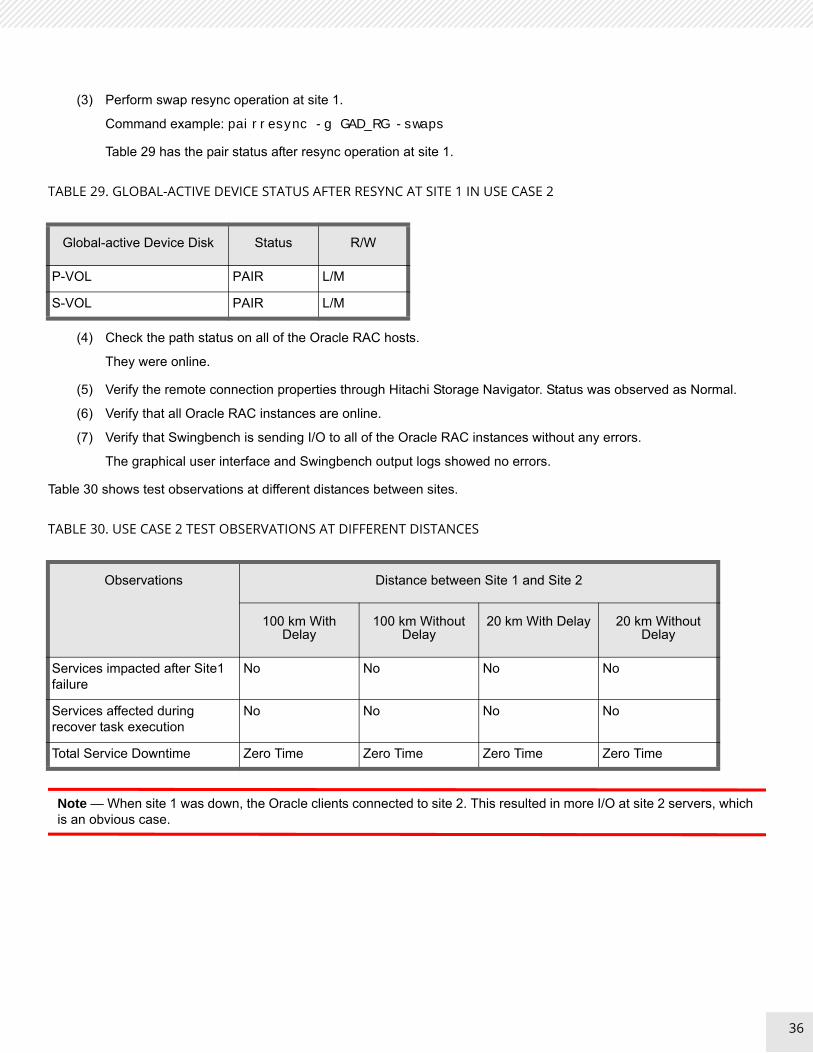
Table 29 has the pair status after resync operation at site 1.
(4) Check the path status on all of the Oracle RAC hosts.
They were online.
(5) Verify the remote connection properties through Hitachi Storage Navigator. Status was observed as Normal.
(6) Verify that all Oracle RAC instances are online.
(7) Verify that Swingbench is sending I/O to all of the Oracle RAC instances without any errors.
The graphical user interface and Swingbench output logs showed no errors.
Table 30 shows test observations at different distances between sites.
Note — When site 1 was down, the Oracle clients connected to site 2. This resulted in more I/O at site 2 servers, which is an obvious case.
TABLE 29. GLOBAL-ACTIVE DEVICE STATUS AFTER RESYNC AT SITE 1 IN USE CASE 2
Global-active Device Disk Status R/W
P-VOL PAIR L/M
S-VOL PAIR L/M
TABLE 30. USE CASE 2 TEST OBSERVATIONS AT DIFFERENT DISTANCES
Observations Distance between Site 1 and Site 2
100 km With Delay
100 km Without Delay
20 km With Delay 20 km Without Delay
Services impacted after Site1 failure
No No No No
Services affected during recover task execution
No No No No
Total Service Downtime Zero Time Zero Time Zero Time Zero Time
36
37
Use Case 3 — Recover Oracle Database After Quorum Site Failure
This was the objective for Use Case 3:
Recover from a quorum disk failure while Oracle database instances are running at the surviving site
This was the procedure used to evaluate Use Case 3:
1. System Status Checks
(1) Verify that all paths are online for all Oracle RAC nodes.
Command example: dlnkmgr view -path
(2) Verify that all disk pairs are in PAIR status at both the sites.
Command example: pairdisplay -g GAD_RG -fcxe
(3) Verify that database resource is open and stable.
Command example: crsctl stat res -t
(4) Start Swingbench workload with number of users configured as 20.
2. Simulate Failure
Disable the ports used for quorum connections at both the sites.
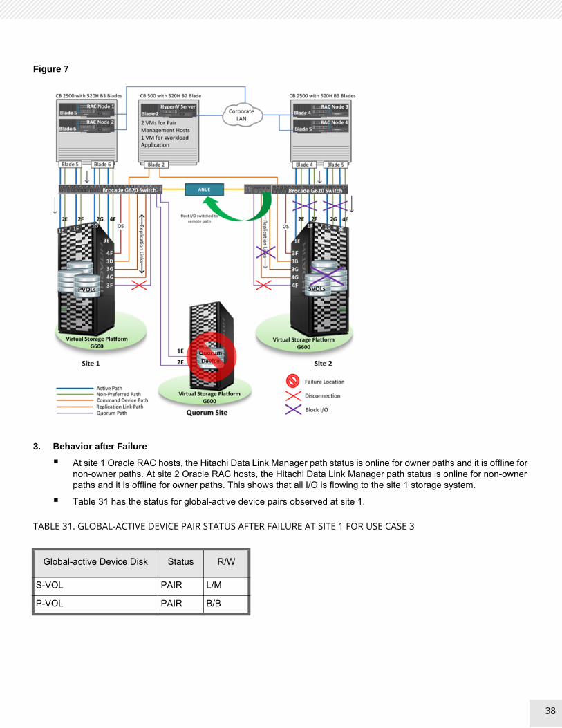
Figure 7 on page 38 shows a quorum device failure.
37
38
Figure 7
3. Behavior after Failure
At site 1 Oracle RAC hosts, the Hitachi Data Link Manager path status is online for owner paths and it is offline for non-owner paths. At site 2 Oracle RAC hosts, the Hitachi Data Link Manager path status is online for non-owner paths and it is offline for owner paths. This shows that all I/O is flowing to the site 1 storage system.
Table 31 has the status for global-active device pairs observed at site 1.
TABLE 31. GLOBAL-ACTIVE DEVICE PAIR STATUS AFTER FAILURE AT SITE 1 FOR USE CASE 3
Global-active Device Disk Status R/W
S-VOL PAIR L/M
P-VOL PAIR B/B
38
39
Connection Verification through Swingbench
The number of Swingbench user connection is 20. Execute the following SQL statement in one of the available RAC nodes.
SQL>select inst_id, sid, serial#, status, schemaname from gv$session where schemaname = 'GAD_USER' and status ='ACTIVE';
The user of Swingbench disperses to all nodes.
All database instances are in online state.
Checking the database for errors showed no errors into the alert logs.
4. Recovery Procedure
(1) Enable the ports for quorum connections at both the sites.
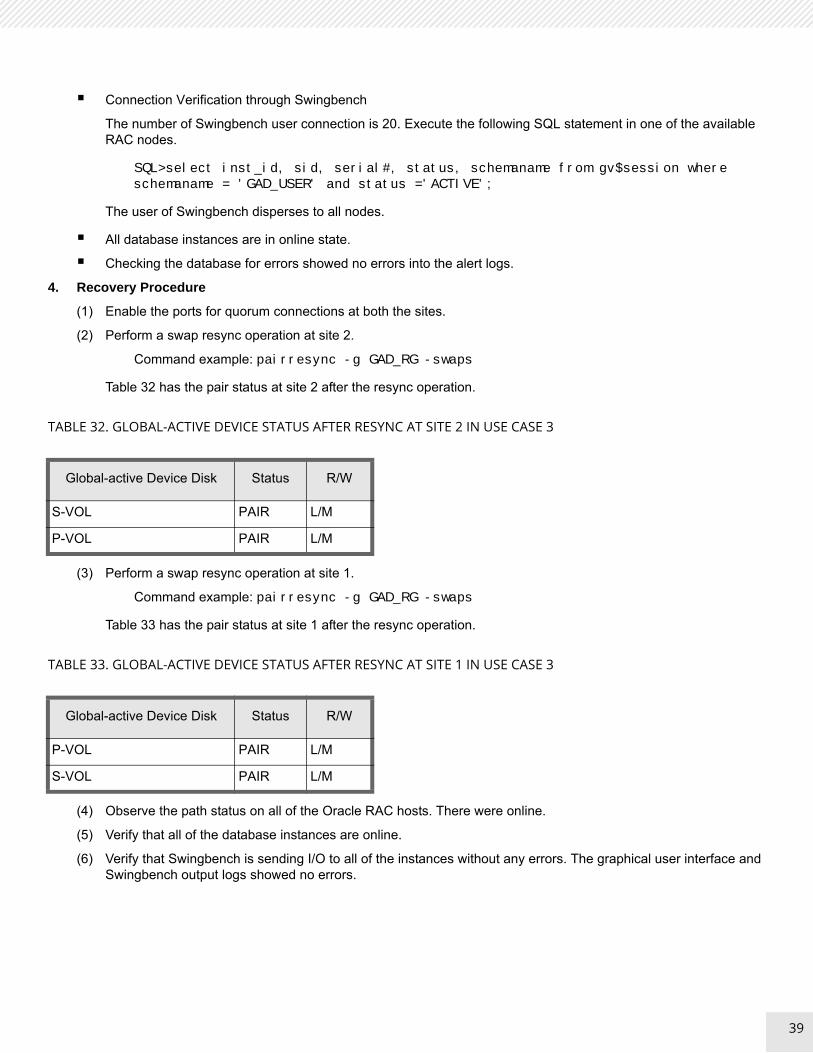
(2) Perform a swap resync operation at site 2.
Command example: pairresync -g GAD_RG -swaps
Table 32 has the pair status at site 2 after the resync operation.
(3) Perform a swap resync operation at site 1.
Command example: pairresync -g GAD_RG -swaps
Table 33 has the pair status at site 1 after the resync operation.
(4) Observe the path status on all of the Oracle RAC hosts. There were online.
(5) Verify that all of the database instances are online.
(6) Verify that Swingbench is sending I/O to all of the instances without any errors. The graphical user interface and Swingbench output logs showed no errors.
TABLE 32. GLOBAL-ACTIVE DEVICE STATUS AFTER RESYNC AT SITE 2 IN USE CASE 3
Global-active Device Disk Status R/W
S-VOL PAIR L/M
P-VOL PAIR L/M
TABLE 33. GLOBAL-ACTIVE DEVICE STATUS AFTER RESYNC AT SITE 1 IN USE CASE 3
Global-active Device Disk Status R/W
P-VOL PAIR L/M
S-VOL PAIR L/M
39
40
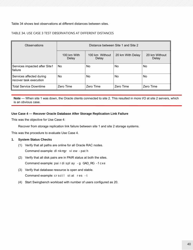
Table 34 shows test observations at different distances between sites.
Note — When site 1 was down, the Oracle clients connected to site 2. This resulted in more I/O at site 2 servers, which is an obvious case.
Use Case 4 — Recover Oracle Database After Storage Replication Link Failure
This was the objective for Use Case 4:
Recover from storage replication link failure between site 1 and site 2 storage systems.
This was the procedure to evaluate Use Case 4.
1. System Status Checks
(1) Verify that all paths are online for all Oracle RAC nodes.
Command example: dlnkmgr view -path
(2) Verify that all disk pairs are in PAIR status at both the sites.
Command example: pairdisplay -g GAD_RG -fcxe
(3) Verify that database resource is open and stable.
Command example: crsctl stat res -t
(4) Start Swingbench workload with number of users configured as 20.
TABLE 34. USE CASE 3 TEST OBSERVATIONS AT DIFFERENT DISTANCES
Observations Distance between Site 1 and Site 2
100 km With Delay
100 km Without Delay
20 km With Delay 20 km Without Delay
Services impacted after Site1 failure
No No No No
Services affected during recover task execution
No No No No
Total Service Downtime Zero Time Zero Time Zero Time Zero Time
40
41
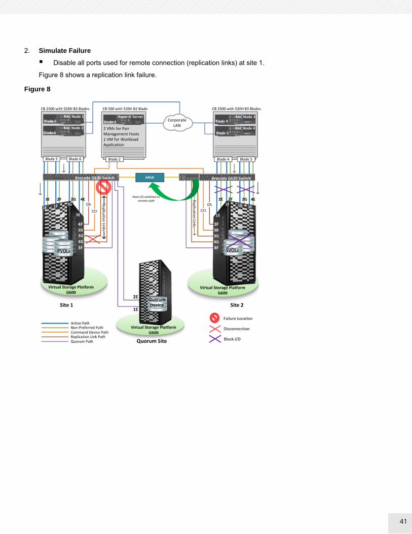
2. Simulate Failure
Disable all ports used for remote connection (replication links) at site 1.
Figure 8 shows a replication link failure.
Figure 8
41
42
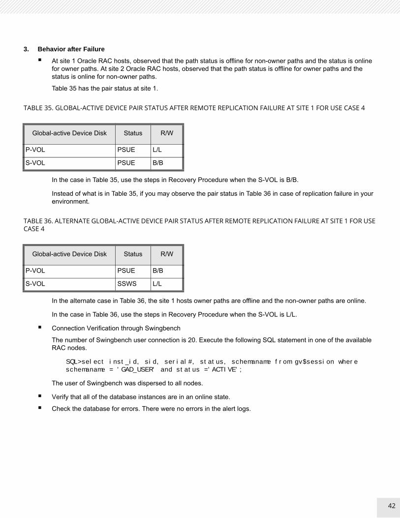
3. Behavior after Failure
At site 1 Oracle RAC hosts, observed that the path status is offline for non-owner paths and the status is online for owner paths. At site 2 Oracle RAC hosts, observed that the path status is offline for owner paths and the status is online for non-owner paths.
Table 35 has the pair status at site 1.
In the case in Table 35, use the steps in Recovery Procedure when the S-VOL is B/B.
Instead of what is in Table 35, if you may observe the pair status in Table 36 in case of replication failure in your environment.
In the alternate case in Table 36, the site 1 hosts owner paths are offline and the non-owner paths are online.
In the case in Table 36, use the steps in Recovery Procedure when the S-VOL is L/L.
Connection Verification through Swingbench
The number of Swingbench user connection is 20. Execute the following SQL statement in one of the available RAC nodes.
SQL>select inst_id, sid, serial#, status, schemaname from gv$session where schemaname = 'GAD_USER' and status ='ACTIVE';
The user of Swingbench was dispersed to all nodes.
Verify that all of the database instances are in an online state.
Check the database for errors. There were no errors in the alert logs.
TABLE 35. GLOBAL-ACTIVE DEVICE PAIR STATUS AFTER REMOTE REPLICATION FAILURE AT SITE 1 FOR USE CASE 4
Global-active Device Disk Status R/W
P-VOL PSUE L/L
S-VOL PSUE B/B
TABLE 36. ALTERNATE GLOBAL-ACTIVE DEVICE PAIR STATUS AFTER REMOTE REPLICATION FAILURE AT SITE 1 FOR USE CASE 4
Global-active Device Disk Status R/W
P-VOL PSUE B/B
S-VOL SSWS L/L
42
43
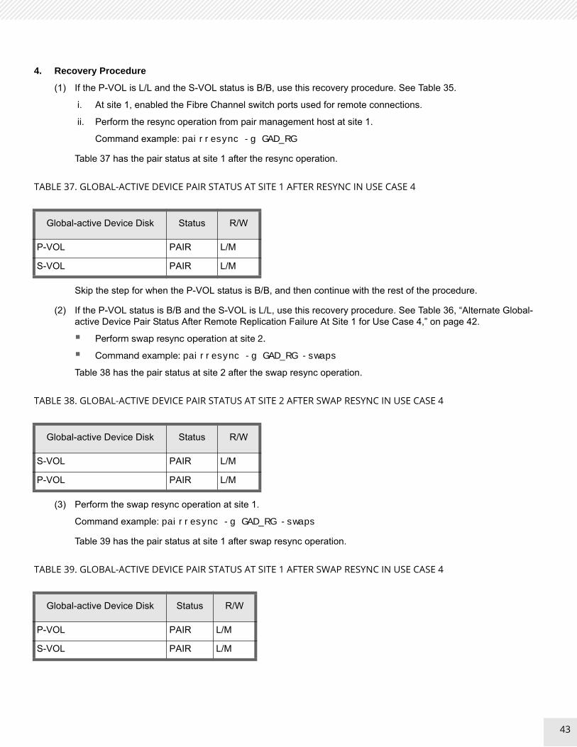
4. Recovery Procedure
(1) If the P-VOL is L/L and the S-VOL status is B/B, use this recovery procedure. See Table 35.
i. At site 1, enabled the Fibre Channel switch ports used for remote connections.
ii. Perform the resync operation from pair management host at site 1.
Command example: pairresync -g GAD_RG
Table 37 has the pair status at site 1 after the resync operation.
Skip the step for when the P-VOL status is B/B, and then continue with the rest of the procedure.
(2) If the P-VOL status is B/B and the S-VOL is L/L, use this recovery procedure. See Table 36, “Alternate Global-active Device Pair Status After Remote Replication Failure At Site 1 for Use Case 4,” on page 42.
Perform swap resync operation at site 2.
Command example: pairresync -g GAD_RG -swaps
Table 38 has the pair status at site 2 after the swap resync operation.
(3) Perform the swap resync operation at site 1.
Command example: pairresync -g GAD_RG -swaps
Table 39 has the pair status at site 1 after swap resync operation.
TABLE 37. GLOBAL-ACTIVE DEVICE PAIR STATUS AT SITE 1 AFTER RESYNC IN USE CASE 4
Global-active Device Disk Status R/W
P-VOL PAIR L/M
S-VOL PAIR L/M
TABLE 38. GLOBAL-ACTIVE DEVICE PAIR STATUS AT SITE 2 AFTER SWAP RESYNC IN USE CASE 4
Global-active Device Disk Status R/W
S-VOL PAIR L/M
P-VOL PAIR L/M
TABLE 39. GLOBAL-ACTIVE DEVICE PAIR STATUS AT SITE 1 AFTER SWAP RESYNC IN USE CASE 4
Global-active Device Disk Status R/W
P-VOL PAIR L/M
S-VOL PAIR L/M
43
44
(4) Observe path status on all of the Oracle RAC hosts. They were online.
(5) Verify the remote connection properties through Hitachi Storage Navigator. The status was observed as Normal.
(6) Observe that all of the instances were online.
(7) Verify that Swingbench is sending I/O to all of the instances without any errors. The graphical user interface and Swingbench output logs Showed no errors.
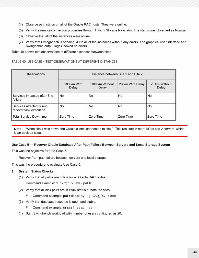
Table 40 shows test observations at different distances between sites.
Note — When site 1 was down, the Oracle clients connected to site 2. This resulted in more I/O at site 2 servers, which is an obvious case.
Use Case 5 — Recover Oracle Database After Path Failure Between Servers and Local Storage System
This was the objective for Use Case 5:
Recover from path failure between servers and local storage.
This was the procedure to evaluate Use Case 5.
1. System Status Checks
(1) Verify that all paths are online for all Oracle RAC nodes.
Command example: dlnkmgr view -path
(2) Verify that all disk pairs are in PAIR status at both the sites.
Command example: pairdisplay -g GAD_RG -fcxe
(3) Verify that database resource is open and stable.
Command example: crsctl stat res -t
(4) Start Swingbench workload with number of users configured as 20.
TABLE 40. USE CASE 4 TEST OBSERVATIONS AT DIFFERENT DISTANCES
Observations Distance between Site 1 and Site 2
100 km With Delay
100 km Without Delay
20 km With Delay 20 km Without Delay
Services impacted after Site1 failure
No No No No
Services affected during recover task execution
No No No No
Total Service Downtime Zero Time Zero Time Zero Time Zero Time
44
45
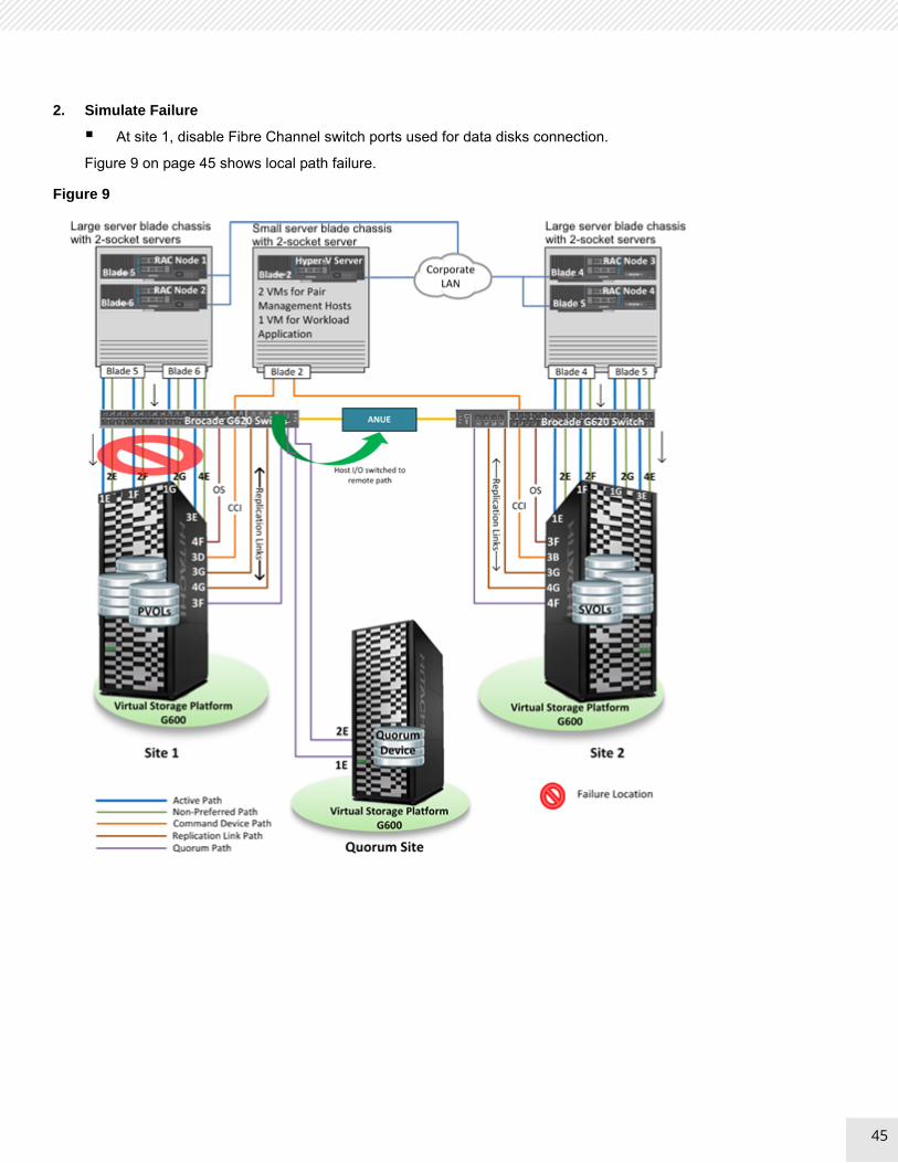
2. Simulate Failure
At site 1, disable Fibre Channel switch ports used for data disks connection.
Figure 9 on page 45 shows local path failure.
Figure 9
45
46
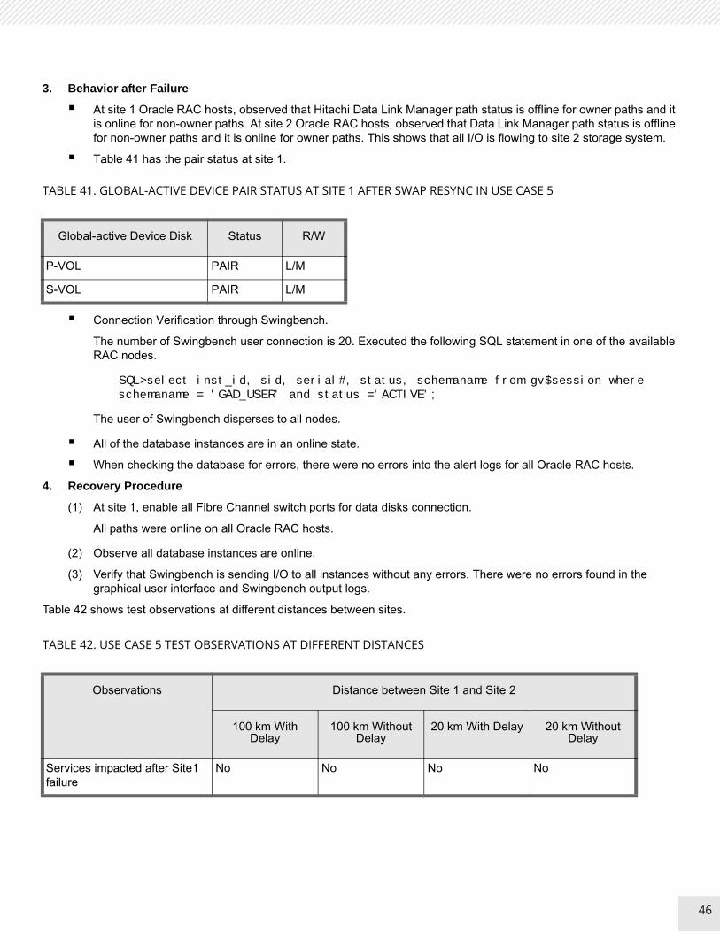
3. Behavior after Failure
At site 1 Oracle RAC hosts, observed that Hitachi Data Link Manager path status is offline for owner paths and it is online for non-owner paths. At site 2 Oracle RAC hosts, observed that Data Link Manager path status is offline for non-owner paths and it is online for owner paths. This shows that all I/O is flowing to site 2 storage system.
Table 41 has the pair status at site 1.
Connection Verification through Swingbench.
The number of Swingbench user connection is 20. Executed the following SQL statement in one of the available RAC nodes.
SQL>select inst_id, sid, serial#, status, schemaname from gv$session where schemaname = 'GAD_USER' and status ='ACTIVE';
The user of Swingbench disperses to all nodes.
All of the database instances are in an online state.
When checking the database for errors, there were no errors into the alert logs for all Oracle RAC hosts.
4. Recovery Procedure
(1) At site 1, enable all Fibre Channel switch ports for data disks connection.
All paths were online on all Oracle RAC hosts.
(2) Observe all database instances are online.
(3) Verify that Swingbench is sending I/O to all instances without any errors. There were no errors found in the graphical user interface and Swingbench output logs.
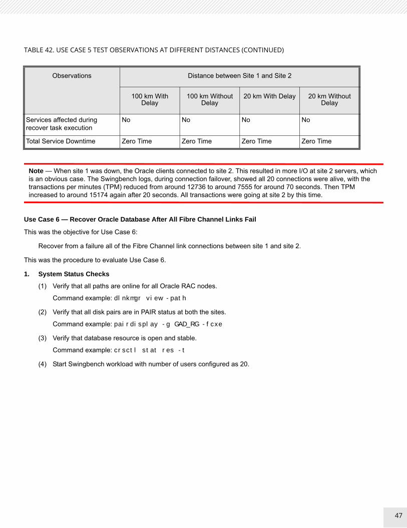
Table 42 shows test observations at different distances between sites.
TABLE 41. GLOBAL-ACTIVE DEVICE PAIR STATUS AT SITE 1 AFTER SWAP RESYNC IN USE CASE 5
Global-active Device Disk Status R/W
P-VOL PAIR L/M
S-VOL PAIR L/M
TABLE 42. USE CASE 5 TEST OBSERVATIONS AT DIFFERENT DISTANCES
Observations Distance between Site 1 and Site 2
100 km With Delay
100 km Without Delay
20 km With Delay 20 km Without Delay
Services impacted after Site1 failure
No No No No
46
47
Note — When site 1 was down, the Oracle clients connected to site 2. This resulted in more I/O at site 2 servers, which is an obvious case. The Swingbench logs, during connection failover, showed all 20 connections were alive, with the transactions per minutes (TPM) reduced from around 12736 to around 7555 for around 70 seconds. Then TPM increased to around 15174 again after 20 seconds. All transactions were going at site 2 by this time.
Use Case 6 — Recover Oracle Database After All Fibre Channel Links Fail
This was the objective for Use Case 6:
Recover from a failure all of the Fibre Channel link connections between site 1 and site 2.
This was the procedure to evaluate Use Case 6.
1. System Status Checks
(1) Verify that all paths are online for all Oracle RAC nodes.
Command example: dlnkmgr view -path
(2) Verify that all disk pairs are in PAIR status at both the sites.
Command example: pairdisplay -g GAD_RG -fcxe
(3) Verify that database resource is open and stable.
Command example: crsctl stat res -t
(4) Start Swingbench workload with number of users configured as 20.
Services affected during recover task execution
No No No No
Total Service Downtime Zero Time Zero Time Zero Time Zero Time
TABLE 42. USE CASE 5 TEST OBSERVATIONS AT DIFFERENT DISTANCES (CONTINUED)
Observations Distance between Site 1 and Site 2
100 km With Delay
100 km Without Delay
20 km With Delay 20 km Without Delay
47
48
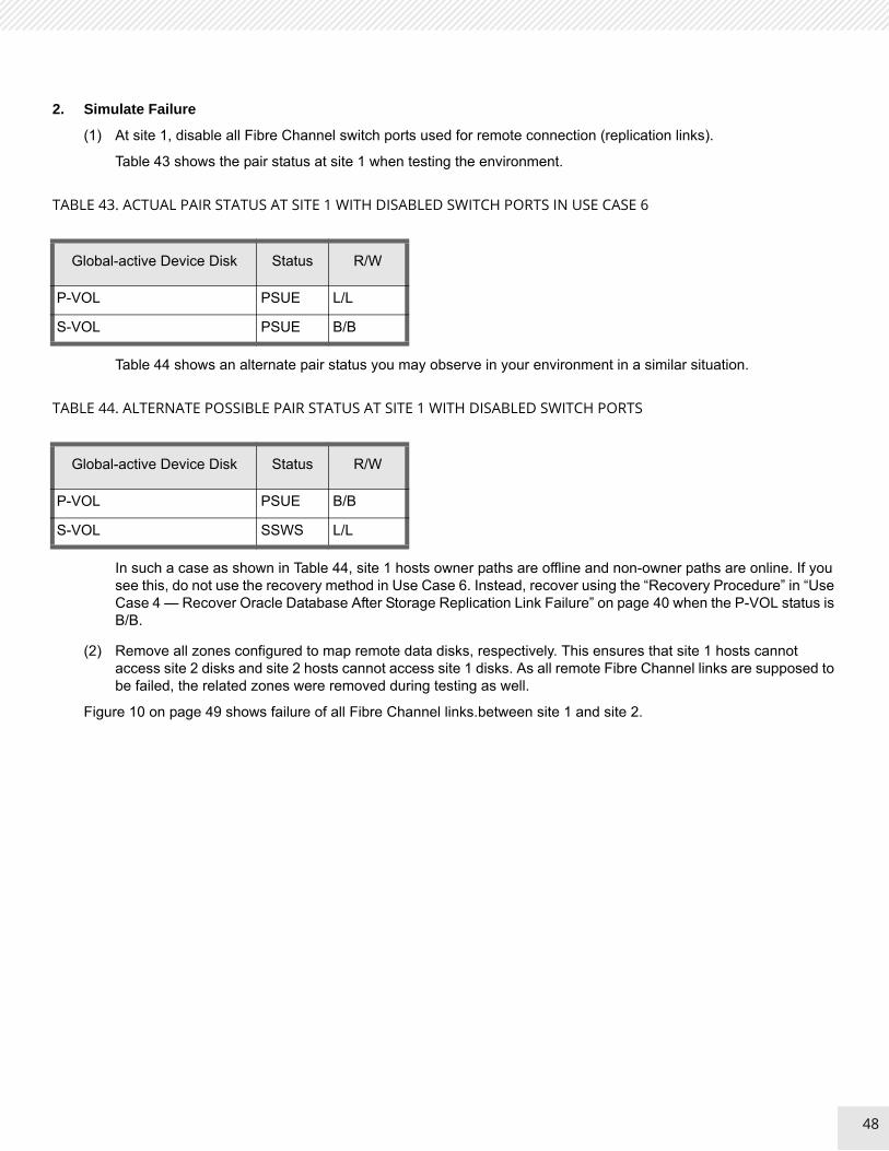
2. Simulate Failure
(1) At site 1, disable all Fibre Channel switch ports used for remote connection (replication links).
Table 43 shows the pair status at site 1 when testing the environment.
Table 44 shows an alternate pair status you may observe in your environment in a similar situation.
In such a case as shown in Table 44, site 1 hosts owner paths are offline and non-owner paths are online. If you see this, do not use the recovery method in Use Case 6. Instead, recover using the “Recovery Procedure” in “Use Case 4 — Recover Oracle Database After Storage Replication Link Failure” on page 40 when the P-VOL status is B/B.
(2) Remove all zones configured to map remote data disks, respectively. This ensures that site 1 hosts cannot access site 2 disks and site 2 hosts cannot access site 1 disks. As all remote Fibre Channel links are supposed to be failed, the related zones were removed during testing as well.
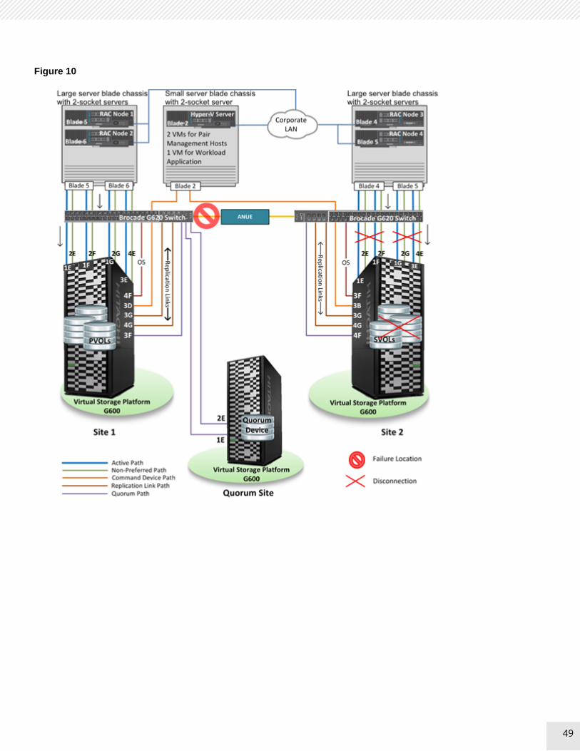
Figure 10 on page 49 shows failure of all Fibre Channel links.between site 1 and site 2.
TABLE 43. ACTUAL PAIR STATUS AT SITE 1 WITH DISABLED SWITCH PORTS IN USE CASE 6
Global-active Device Disk Status R/W
P-VOL PSUE L/L
S-VOL PSUE B/B
TABLE 44. ALTERNATE POSSIBLE PAIR STATUS AT SITE 1 WITH DISABLED SWITCH PORTS
Global-active Device Disk Status R/W
P-VOL PSUE B/B
S-VOL SSWS L/L
48
49
Figure 10
49
50
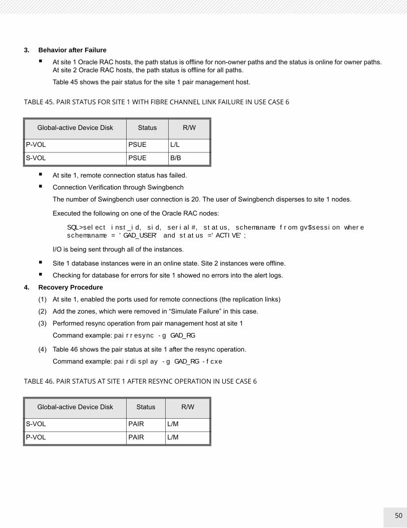
3. Behavior after Failure
At site 1 Oracle RAC hosts, the path status is offline for non-owner paths and the status is online for owner paths. At site 2 Oracle RAC hosts, the path status is offline for all paths.
Table 45 shows the pair status for the site 1 pair management host.
At site 1, remote connection status has failed.
Connection Verification through Swingbench
The number of Swingbench user connection is 20. The user of Swingbench disperses to site 1 nodes.
Executed the following on one of the Oracle RAC nodes:
SQL>select inst_id, sid, serial#, status, schemaname from gv$session where schemaname = 'GAD_USER' and status ='ACTIVE';
I/O is being sent through all of the instances.
Site 1 database instances were in an online state. Site 2 instances were offline.
Checking for database for errors for site 1 showed no errors into the alert logs.
4. Recovery Procedure
(1) At site 1, enabled the ports used for remote connections (the replication links)
(2) Add the zones, which were removed in “Simulate Failure” in this case.
(3) Performed resync operation from pair management host at site 1
Command example: pairresync -g GAD_RG
(4) Table 46 shows the pair status at site 1 after the resync operation.
Command example: pairdisplay -g GAD_RG -fcxe
TABLE 45. PAIR STATUS FOR SITE 1 WITH FIBRE CHANNEL LINK FAILURE IN USE CASE 6
Global-active Device Disk Status R/W
P-VOL PSUE L/L
S-VOL PSUE B/B
TABLE 46. PAIR STATUS AT SITE 1 AFTER RESYNC OPERATION IN USE CASE 6
Global-active Device Disk Status R/W
S-VOL PAIR L/M
P-VOL PAIR L/M
50
51
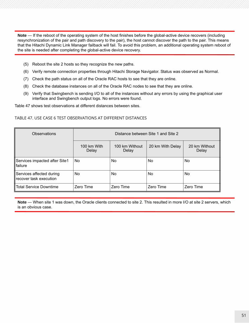
Note — If the reboot of the operating system of the host finishes before the global-active device recovers (including resynchronization of the pair and path discovery to the pair), the host cannot discover the path to the pair. This means that the Hitachi Dynamic Link Manager failback will fail. To avoid this problem, an additional operating system reboot of the site is needed after completing the global-active device recovery.
(5) Reboot the site 2 hosts so they recognize the new paths.
(6) Verify remote connection properties through Hitachi Storage Navigator. Status was observed as Normal.
(7) Check the path status on all of the Oracle RAC hosts to see that they are online.
(8) Check the database instances on all of the Oracle RAC nodes to see that they are online.
(9) Verify that Swingbench is sending I/O to all of the instances without any errors by using the graphical user interface and Swingbench output logs. No errors were found.
Table 47 shows test observations at different distances between sites.
Note — When site 1 was down, the Oracle clients connected to site 2. This resulted in more I/O at site 2 servers, which is an obvious case.
TABLE 47. USE CASE 6 TEST OBSERVATIONS AT DIFFERENT DISTANCES
Observations Distance between Site 1 and Site 2
100 km With Delay
100 km Without Delay
20 km With Delay 20 km Without Delay
Services impacted after Site1 failure
No No No No
Services affected during recover task execution
No No No No
Total Service Downtime Zero Time Zero Time Zero Time Zero Time
51
52
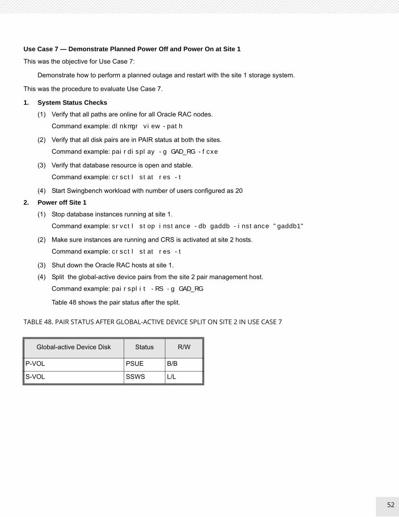
Use Case 7 — Demonstrate Planned Power Off and Power On at Site 1
This was the objective for Use Case 7:
Demonstrate how to perform a planned outage and restart with the site 1 storage system.
This was the procedure to evaluate Use Case 7.
1. System Status Checks
(1) Verify that all paths are online for all Oracle RAC nodes.
Command example: dlnkmgr view -path
(2) Verify that all disk pairs are in PAIR status at both the sites.
Command example: pairdisplay -g GAD_RG -fcxe
(3) Verify that database resource is open and stable.
Command example: crsctl stat res -t
(4) Start Swingbench workload with number of users configured as 20
2. Power off Site 1
(1) Stop database instances running at site 1.
Command example: srvctl stop instance -db gaddb -instance "gaddb1"
(2) Make sure instances are running and CRS is activated at site 2 hosts.
Command example: crsctl stat res -t
(3) Shut down the Oracle RAC hosts at site 1.
(4) Split the global-active device pairs from the site 2 pair management host.
Command example: pairsplit -RS -g GAD_RG
Table 48 shows the pair status after the split.
TABLE 48. PAIR STATUS AFTER GLOBAL-ACTIVE DEVICE SPLIT ON SITE 2 IN USE CASE 7
Global-active Device Disk Status R/W
P-VOL PSUE B/B
S-VOL SSWS L/L
52
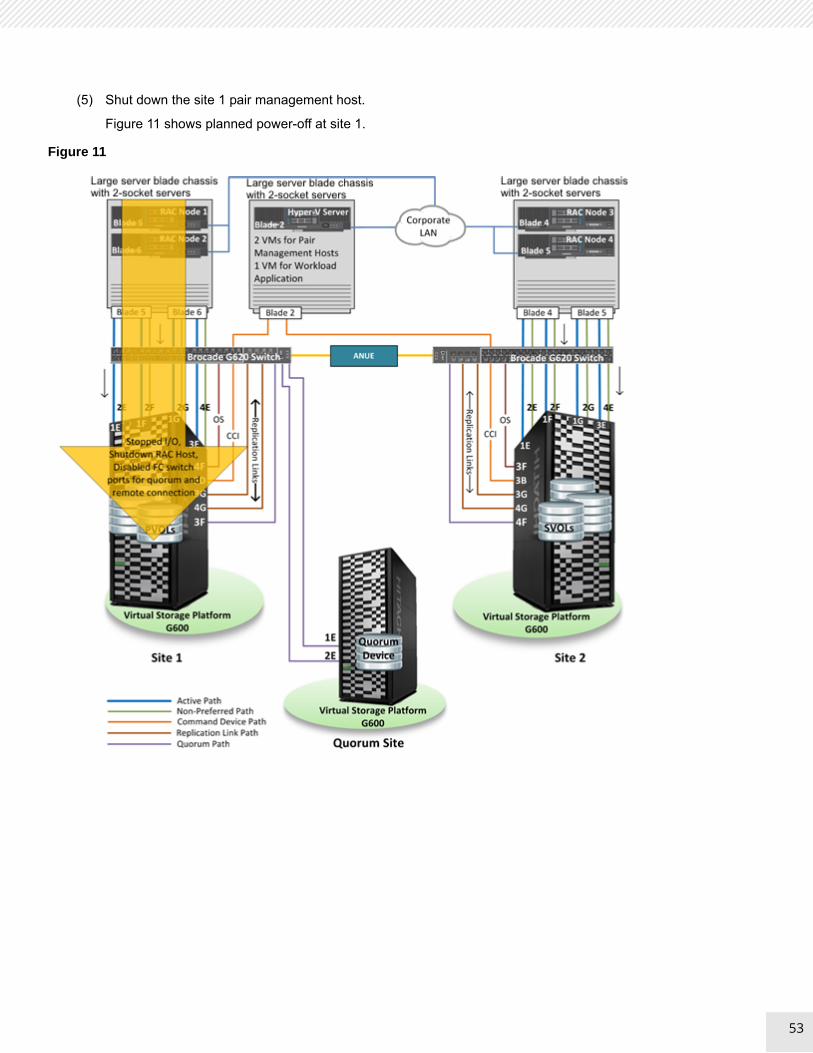
53
(5) Shut down the site 1 pair management host.
Figure 11 shows planned power-off at site 1.
Figure 11
53
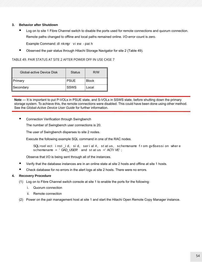
54
3. Behavior after Shutdown
Log on to site 1 Fibre Channel switch to disable the ports used for remote connections and quorum connection.
Remote paths changed to offline and local paths remained online. I/O-error count is zero.
Example Command: dlnkmgr view -path
Observed the pair status through Hitachi Storage Navigator for site 2 (Table 49).
Note — It is important to put P-VOLs in PSUE state, and S-VOLs in SSWS state, before shutting down the primary storage system. To achieve this, the remote connections were disabled. This could have been done using other method. See the Global-Active Device User Guide for further information.
Connection Verification through Swingbench
The number of Swingbench user connections is 20.
The user of Swingbench disperses to site 2 nodes.
Execute the following example SQL command in one of the RAC nodes.
SQL>select inst_id, sid, serial#, status, schemaname from gv$session where schemaname = 'GAD_USER' and status ='ACTIVE';
Observe that I/O is being sent through all of the instances.
Verify that the database instances are in an online state at site 2 hosts and offline at site 1 hosts.
Check database for no errors in the alert logs at site 2 hosts. There were no errors.
4. Recovery Procedure
(1) Log on to Fibre Channel switch console at site 1 to enable the ports for the following:
i. Quorum connection
ii. Remote connection
(2) Power on the pair management host at site 1 and start the Hitachi Open Remote Copy Manager instance.
TABLE 49. PAIR STATUS AT SITE 2 AFTER POWER OFF IN USE CASE 7
Global-active Device Disk Status R/W
Primary PSUE Block
Secondary SSWS Local
54
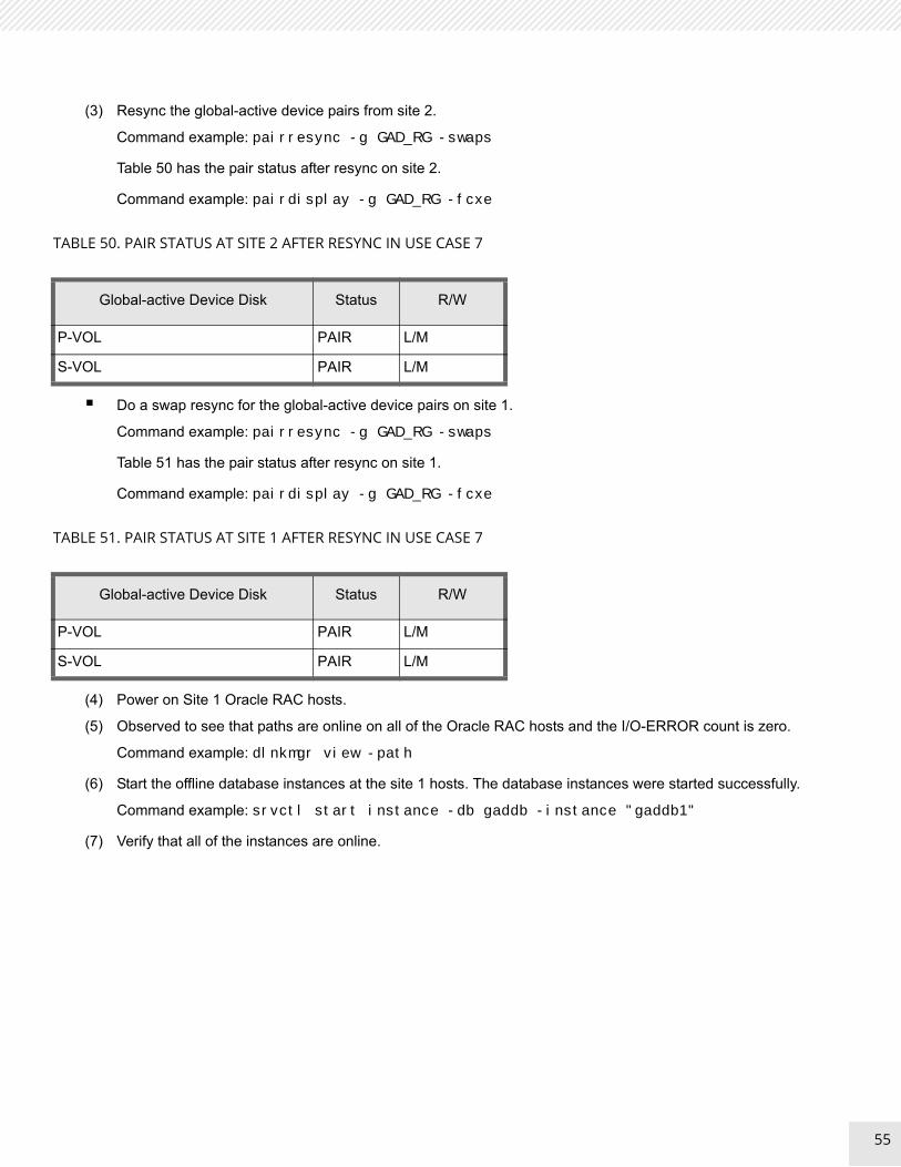
55
(3) Resync the global-active device pairs from site 2.
Command example: pairresync -g GAD_RG -swaps
Table 50 has the pair status after resync on site 2.
Command example: pairdisplay -g GAD_RG -fcxe
Do a swap resync for the global-active device pairs on site 1.
Command example: pairresync -g GAD_RG -swaps
Table 51 has the pair status after resync on site 1.
Command example: pairdisplay -g GAD_RG -fcxe
(4) Power on Site 1 Oracle RAC hosts.
(5) Observed to see that paths are online on all of the Oracle RAC hosts and the I/O-ERROR count is zero.
Command example: dlnkmgr view -path
(6) Start the offline database instances at the site 1 hosts. The database instances were started successfully.
Command example: srvctl start instance -db gaddb -instance "gaddb1"
(7) Verify that all of the instances are online.
TABLE 50. PAIR STATUS AT SITE 2 AFTER RESYNC IN USE CASE 7
Global-active Device Disk Status R/W
P-VOL PAIR L/M
S-VOL PAIR L/M
TABLE 51. PAIR STATUS AT SITE 1 AFTER RESYNC IN USE CASE 7
Global-active Device Disk Status R/W
P-VOL PAIR L/M
S-VOL PAIR L/M
55
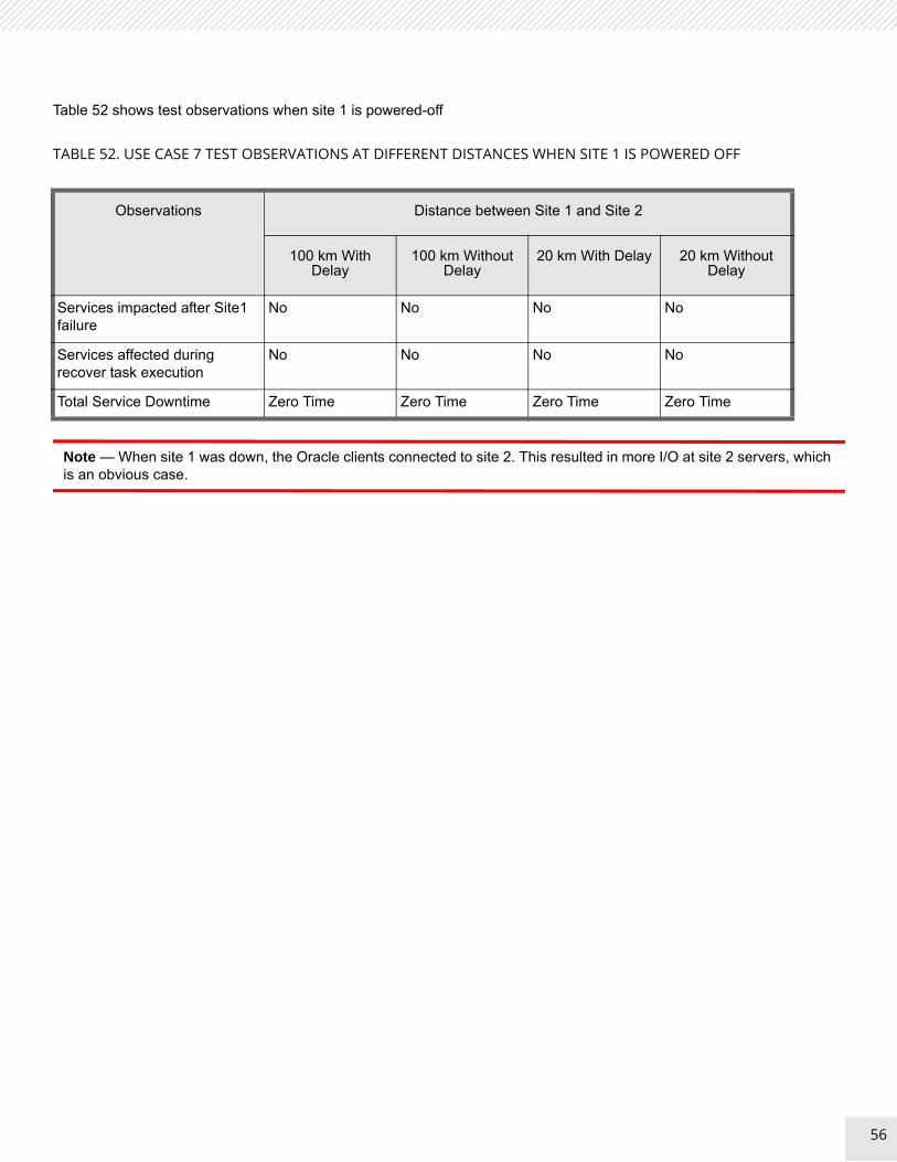
56
Table 52 shows test observations when site 1 is powered-off
Note — When site 1 was down, the Oracle clients connected to site 2. This resulted in more I/O at site 2 servers, which is an obvious case.
TABLE 52. USE CASE 7 TEST OBSERVATIONS AT DIFFERENT DISTANCES WHEN SITE 1 IS POWERED OFF
Observations Distance between Site 1 and Site 2
100 km With Delay
100 km Without Delay
20 km With Delay 20 km Without Delay
Services impacted after Site1 failure
No No No No
Services affected during recover task execution
No No No No
Total Service Downtime Zero Time Zero Time Zero Time Zero Time
56

1
Corporate Headquarters2845 Lafayette StreetSanta Clara, CA 96050-2639 USAHitachiVantara.com | community.HitachiVantara.com
Contact InformationUSA: 1-8000446-0744Global: 1-858-547-4526HitachiVantara.com/contact
Hitachi Vantara
© Hitachi Vantara Corporation 2018. All rights reserved. HITACHI is a trademark or registered trademark of Hitachi, Ltd. VSP is a trademark or registered trademark of Hitachi Vantara Corporation. Microsoft, Windows Server, and Hyper-V are trademarks or registered trademarks of Microsoft Corporation. All other trademarks, service marks, and company names are properties of their respective owners.
Notice: This document is for informational purposes only, and does not set forth any warranty, expressed or implied, concerning any equipment or service offered or to be offered by Hitachi Vantara Corporation.
MK-SL-077-00. June 2018.