Embed Size (px)
Citation preview

electronics
Article
Protecting Private Communications in Cyber-PhysicalSystems through Physical Unclonable Functions
Marina Pérez-Jiménez 1, Borja Bordel Sánchez 2,* , Andrea Migliorini 3 andRamón Alcarria 2
1 Instituto de Sistemas Optoelectrónicos y Microtecnología. Universidad Politécnica de Madrid, 28040 Madrid,Spain; [email protected]
2 Department of Geospatial Engineering. Universidad Politécnica de Madrid, 28031 Madrid, Spain;[email protected]
3 Max Planck Institute of Microstructure Physics, 06120 Halle, Germany; [email protected]* Correspondence: [email protected]; Tel.: +34-910672167
Received: 31 January 2019; Accepted: 27 March 2019; Published: 1 April 2019�����������������
Abstract: Cyber-physical systems (CPS) are envisioned to change the whole of society.New engineered systems joining physical and digital solutions are being employed in industry,education, etc. These new systems are networked by default, and private information is sharedamong the different components related to users, critical infrastructures, or business operations.In this context, it is essential to encrypt those communication links to protect such information.However, even most complicated schemes based on hybrid (asymmetric and symmetric) solutions,finally require physical devices to store a secret key. This approach is cryptographically weak, as anyperson with physical access to the device could obtain that key. Therefore, in this paper we proposethe use of physical unclonable functions (PUF) to generate secret keys for lightweight encryptionschemes. Using PUFs, any attempt to capture the key is changing the original secret stream, andeven manufacturers are not able to build two identical PUFs. The proposed key generator is basedon magnetic materials and lightweight pseudorandom number generators to meet the low-cost andsmall size requirements of CPS. In particular, materials with an activated exchange-bias effect areemployed, together with simple copper coils. The encryption process can be based on a simple XORgate because of the robustness of the proposed key generator. In order to evaluate the performance ofthe proposed technology, an experimental validation based on simulation scenarios is also provided.
Keywords: cyber-physical systems; physical unclonable functions; streaming communications;security; encryption
1. Introduction
Cyber-physical systems (CPS) [1] are defined as unions between physical and computationalprocesses. This new approach has opened a new era in industry (Industry 4.0) [2], education, andengineering. In CPS, feedback control loops [3] are employed to make physical and cybernetic processesevolve together. Several heterogenous components are interconnected to create pervasive systemssupporting these mechanisms. This new paradigm is particularly interesting to support real-timecontrol systems, fed by an information stream (biological signals, data from sensors, etc.) [4].
However, these new systems are also vulnerable to new, innovative, and more aggressive attacks,known as ‘cyber-physical attacks’ [5]. In fact, as CPS are made of many interconnected components,attacks may affect a critical component when non-relevant (and often less secure) elements fail andthe failure propagates due to a cascade effect. Besides, CPS are vulnerable not only to cybercrimes,but also to physical attacks. Thus, in these new systems, not only must attackers accessing to the
Electronics 2019, 8, 390; doi:10.3390/electronics8040390 www.mdpi.com/journal/electronics

Electronics 2019, 8, 390 2 of 22
system through the communication networks be considered, but also people physically accessing andmanipulating any device [6].
In this context, security for CPS is a critical issue. Many different schemes and solutions, then,have been proposed. Symmetric and asymmetric encryption schemes [7] or certificateless public keyinfrastructures [8] are probably some of the most common proposals. Nevertheless, those solutionsand any other previously reported, finally require physical devices to store a secret key.
Software components can protect secret keys through cyber-protection technologies, as they haveno physical existence, only logical. However, hardware devices must include memory (ROM memory)to store permanent information such as secret keys [9]. This configuration is vulnerable to physicalattacks (i.e., people physically manipulating the device), as the key could be read from the memoryby unauthorized people. This risk, moreover, is especially relevant in CPS, as many deployments areisolated, unmanaged, and unattended [10]. New mechanisms to create or protect keys against anycyber or physical attacker are, then, required.
Therefore, in this paper we propose a novel solution to protect communication links in CPS.The proposed encryption scheme is based on symmetric keys generated through physical unclonablefunctions (PUF) [11]. PUFs are systems whose response is unclonable, even if the manufacturingmethod of the system is known. They take advantage of certain naturally occurring physical properties(such as imperfections in dielectric materials) to create systems which are totally unrepeatable evenby the original creator. In this paper, we are defining a new PUF based on magnetic materials whichcan suffer a spontaneous and unclonable modification of their properties thanks to the exchange-biaseffect. This effect only needs an activation process that is done immediately after manufacturing thematerial. Modifications will depend on the room temperature and, probably (there is no conclusiveevidence) on other environmental factors. Besides the activation process, the atomic structure of thematerial greatly affects the final behavior of this PUF. A unique sample of an activated material shouldbe, then, divided into two elements to create the cipher and the receiver.
The objective of this paper is to provide a mathematical and engineering framework for thisnovel encryption scheme and key generator system. It is described the proposed architecture and thephysical foundations of the electronic device supporting the designed PUF. Moreover, using simulationtechniques, the performance of the proposed solution is evaluated.
The rest of the paper is organized as follows: Section 2 describes the state of the art on PUF andsecurity techniques for CPS; Section 3 presents the proposed encryption solution, including the keygenerator and its mathematical foundations; Section 4 describes the proposed performance evaluationand experimental validation; and Section 5 concludes the paper.
2. State of the Art: Physical Unclonable Functions and Encryption in CPS
Although security and CPS is one of the most interesting and popular research topics nowadays,encryption and security schemes for CPS are pretty standard. In particular, as in most applicationscenarios, these solutions can be classified into two groups: symmetric and asymmetric key schemes.
Cyber-physical systems, in particular, are usually solutions exchanging information packets,not information streams. Thus, symmetric key schemes in CPS are usually focused on block ciphers [12]of cyclic redundancy checks (CRC) [13] which can detect and/or correct transmission errors causedby natural or intentional causes. This solution, nevertheless, is very inefficient as the amount ofinformation to be exchanged grows. Nowadays, very large amounts of information need to be shared.
In order to improve efficiency in these symmetric key solutions, hardware-supported schemeshave been reported [14]. Different sequential circuits focused on encryption may be also found.Nevertheless, in real-time applications, even hardware-based block ciphers are not enough, and streamciphers are required. Different proposals may be found, although most authors agree the encryptionsystem must be as simple as possible, and the engineering cost must be put on key generation. In thissense, different techniques and pseudo-random number generators (PRNG) [15] for key creation havebeen described.

Electronics 2019, 8, 390 3 of 22
These symmetric solutions, however, present a very well-known problem: key distribution.Although this is a problem in any system, in CPS where sparse and resource constrained devices mustcommunication through very unsecure links and networks it is more critical if possible. To addressthis problem, asymmetric key solutions have been investigated.
Different proposals to adapt cryptography based on elliptic curves to cyber-physical systems maybe found [16]. In some occasions, even these mathematical procedures are mixed with nondeterministiceffects such as temperature measures to improve the encryption entropy [17]. Employed algorithms arestandard solutions such as ElGamal encryption [18,19], although innovative public key infrastructurehas also been reported to enable, for example, the transmission of signed information (using high-leveldata format as JSON) [20].
As a general problem of any of the previously described solutions, all of them require from devicesto store a secret key in a ROM or non-volatile memory. A very risky situation in CPS.
Other works have considered a totally new approach based on innovative characteristics of CPS.In particular, taxonomies to classify and analyze the attacks to be suffered by CPS [21] have beenproposed. Based on these taxonomies, some intelligent solutions to detect and react to cyber-physicalattacks in the most appropriate manner have been studied [5]. Besides, some domain-specific solutionsmay be also found, especially in the area of Smart Grids [22], industrial control systems [23], or feedbackcontrol loops [24].
Nevertheless, these approaches are totally reactive, and only valid to detect and react to attacksthat are already running. Although these solutions are needed, schemes to prevent those attacks andkeep the private information as a secret are even more important.
In this work, we combine both approaches and define a preventive security scheme (a symmetrickey encryption scheme), but which does not require to store a secret key in memory. This objective isreached thanks to physical unclonable functions (PUF).
PUFs [25] formalize the idea of one-way functions, later named ‘physical random functions’, whichconsist of the use of systems’ random nature properties to identify them [26,27]. In particular, PUFsbenefit from all these effects that are non-controllable or non-repeatable to create unique responsesfrom systems to common excitations or challenges. Up to three different types of PUF have beenreported: non-electric, electric, and intrinsic.
• Non-electronic PUFs [28] include all functions based on non-electric phenomena, although someelectrical components are employed to create challenges or collect responses. These technologiesare the oldest techniques in PUFs and are usually based on optical effects. Optical fibers,lasers, etc., present random and uncontrollable behaviors that may be employed to create a PUF.However, these mechanisms are expensive, complex, and require a very precise manipulation.These conditions do not fit CPS requirements, in general.
• Electronic PUFs [29] are those based on electric analog signals suffering random effects.For example, random and unclonable changes in the voltage threshold of solid-state devices suchas diodes or transistors. These changes create a personal behavior for each device. The mainproblem of these PUFs is they may be difficult to measure.
• Intrinsic PUFs [25] are those that naturally arise when manufacturing a system, whose mainfunction is usually different. For example, in logic circuits, time required by signals to go throughdifferent paths is slightly different and depends on the manufacturing conditions of each specificcircuit (a type of PUF known as an ‘arbitrary PUF’). ‘Ring oscillator PUF’ is also another exampleof intrinsic PUF.
Different applications for PUFs have been described, including security applications. PUFs havebeen employed into two basic schemes: key generators and authentication mechanisms. The oldestPUF proposals are related to RFID systems, which include key generators based on PUFs [30].Some hardware-supported algorithms also include PUFs to increase its entropy [31,32]; andPUF-based random number generators with high randomness levels have been also reported [33,34].

Electronics 2019, 8, 390 4 of 22
Authorization mechanisms [35] are based on challenge–response tables, which are employed tocompare responses to authorization queries.
The proposed encryption mechanism in this work considers an encryption scheme with anelectronic PUF embedded in a key generator, because of its low-cost character and reduced dimensions.Besides, only simple manufacturing processes are required to implement the proposed solution, whichperfectly fits the characteristics of CPS.
3. Proposed Encryption Scheme
In this section, we described the proposed encryption scheme for CPS. The proposed schemeincludes a simple encryption mechanism based on a XOR logic gate, and the PUF-based key generator.
3.1. Proposed Architecture and Global Overview
Figure 1 shows the proposed security solution for cyber-physical systems. In this figure, twodifferent modules are presented: a transmitter and a receiver. In the transmitter, a certain discrete-timedigital information m[n] is collected to be transmitted. This information is injected in a symmetricencryption module, represented by ε[·] operator, together with a key stream k[n]. As a result, anencrypted message e[n] is obtained (1).
e[n] = ε(m[n], k[n]) (1)
Electronics 2018, 7, x FOR PEER REVIEW 4 of 23
Authorization mechanisms [35] are based on challenge–response tables, which are employed to compare responses to authorization queries.
The proposed encryption mechanism in this work considers an encryption scheme with an electronic PUF embedded in a key generator, because of its low-cost character and reduced dimensions. Besides, only simple manufacturing processes are required to implement the proposed solution, which perfectly fits the characteristics of CPS.
3. Proposed Encryption Scheme
In this section, we described the proposed encryption scheme for CPS. The proposed scheme includes a simple encryption mechanism based on a XOR logic gate, and the PUF-based key generator.
3.1. Proposed Architecture and Global Overview
Figure 1 shows the proposed security solution for cyber-physical systems. In this figure, two different modules are presented: a transmitter and a receiver. In the transmitter, a certain discrete-time digital information 𝑚[𝑛] is collected to be transmitted. This information is injected in a symmetric encryption module, represented by 𝜀[∙] operator, together with a key stream 𝑘[𝑛]. As a result, an encrypted message 𝑒[𝑛] is obtained (1). e[n] = 𝜀(𝑚[𝑛], 𝑘[𝑛]) (1)
Figure 1. Global overview of the proposed solution.
This message is then transmitted through a wireless communication module. This module may be based on any existing technology such as Bluetooth, WiFi, or ZigBee. Hereinafter, we are assuming no errors are produced during the wireless transmission or, if produced, they are corrected by the native mechanisms considered by these technologies. For this analysis, thus, we are considering this module as a transparent component. The same solution could be applied to more complex scenarios, but additional mechanisms to manage data transmission should be considered (that are not the focus of this article).
Information is, then, recovered by the receiver. As a symmetric encryption scheme is being employed, the same encryption function may be employed to decrypt the original information (2). To this function, in this case, it is injected the encrypted message 𝑒[𝑛] and the key stream generated by the receiver 𝑘∗[𝑛]. A clear information 𝑚∗[𝑛] is then obtained. 𝑚∗[𝑛] = 𝜀(𝑒[𝑛], 𝑘∗[𝑛]) (2)
The recovered information 𝑚∗[𝑛] is only equivalent to the original information 𝑚[𝑛] only if encryption key 𝑘[𝑛] and decryption key 𝑘∗[𝑛] are equal. To guarantee both key streams have exactly the same sequence, a synchronization signal 𝑠[𝑛] is calculated and injected into the receiver’s
Figure 1. Global overview of the proposed solution.
This message is then transmitted through a wireless communication module. This module maybe based on any existing technology such as Bluetooth, WiFi, or ZigBee. Hereinafter, we are assumingno errors are produced during the wireless transmission or, if produced, they are corrected by thenative mechanisms considered by these technologies. For this analysis, thus, we are considering thismodule as a transparent component. The same solution could be applied to more complex scenarios,but additional mechanisms to manage data transmission should be considered (that are not the focusof this article).
Information is, then, recovered by the receiver. As a symmetric encryption scheme is beingemployed, the same encryption function may be employed to decrypt the original information (2).To this function, in this case, it is injected the encrypted message e[n] and the key stream generated bythe receiver k∗[n]. A clear information m∗[n] is then obtained.
m∗[n] = ε(e[n], k∗[n]) (2)
The recovered information m∗[n] is only equivalent to the original information m[n] only ifencryption key k[n] and decryption key k∗[n] are equal. To guarantee both key streams have exactly thesame sequence, a synchronization signal s[n] is calculated and injected into the receiver’s key generator.
Electronics 2019, 8, 390 5 of 22
This assumption may be hard to fulfill but different schemes have implemented this mechanismsuccessfully [15,36]. In particular, in our work, we are employing physical unclonable functions.The key generator design based on PUF (see Section 3.3) guarantees the same sequence is generated inboth the transmitter and the receiver (Sections 3.3 and 4 will provide evidence about this requirement).The described synchronization signal ensures, besides, both sequences present the same time base (asseen below).
This synchronization signal is calculated through a correlation algorithm in the synchronizationmodule (3). In this algorithm, a simple correlation estimator c[r] between both key streams is obtained.As the key generator guarantees both key streams (N bits length sequences in the transmitter andthe receiver) are the same sequence, it is only necessary to analyze the delay r between both keys.The delay to be corrected in the receiver’s key is the value for which c[r] is maximum.
c[r] =N−1−r
∑n=0
k[n + r]·k∗[n] (3)
With this synchronization correction, both stream keys are exactly the same sequence [37], andthe symmetric encryption algorithm in the receiver may recover the original information.
3.2. Encryption Mechanism
Any existing or new symmetric encryption algorithm could be integrated in the proposedarchitecture. However, devices in CPSs tend to be resource constrained and, then, computationallylow-cost algorithms are preferred. Thus, in this work we propose the use of the XOR (ExclusiveOR) encryption. The XOR operation is also employed in some existing encryption solutions such asthe Vernam cipher [37] or the one-time pad [38]. However, these mechanisms include some otherconfigurations (such as the key structure or the data format) which are not valid in our proposal. Thus,we are referring the basic encryption technology supporting all these schemes: XOR operation.
This encryption scheme may be easily implemented using a logic gate, and the obtainedsecurity level is sufficiently high. Mathematical evaluations can prove this result depends on therandomness of the key stream. In fact, XOR-based encryption presents some vulnerabilities (such asthe known-plaintext attack), but most of them are addressed below with the appropriate key generatorand, in any case, the balance between the reached security level and the lightweight implementationin XOR encryption is adequate for CPSs [39].
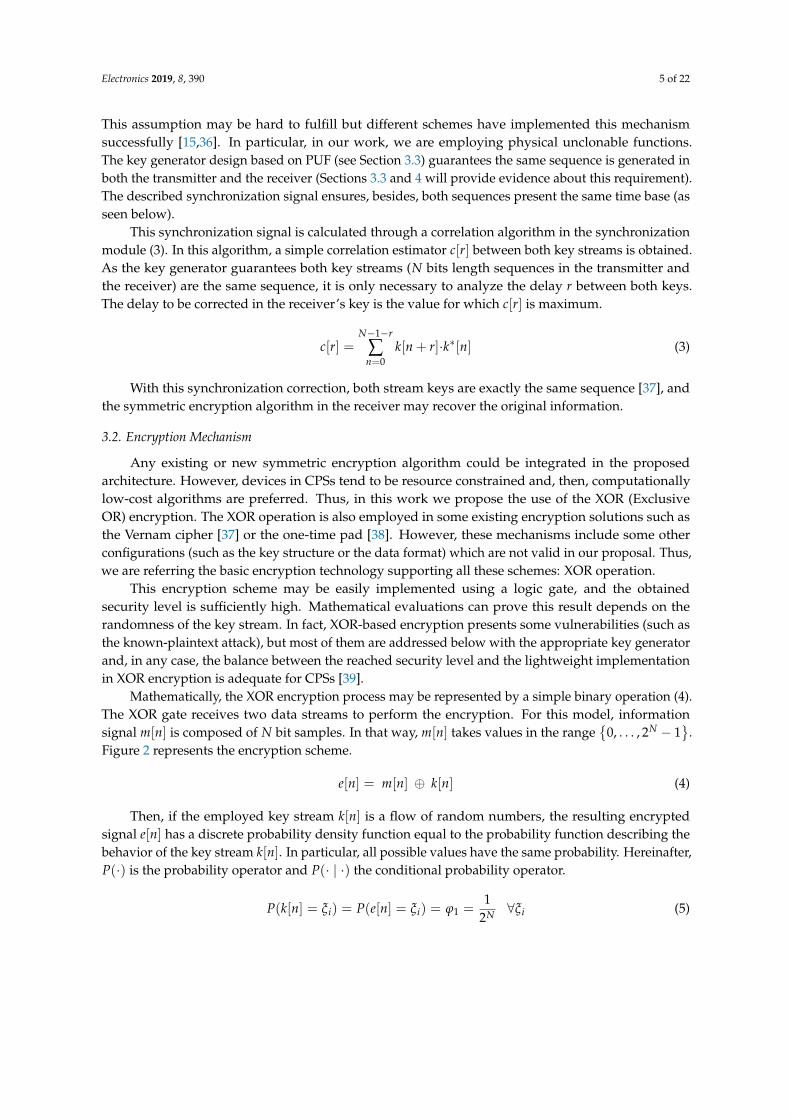
Mathematically, the XOR encryption process may be represented by a simple binary operation (4).The XOR gate receives two data streams to perform the encryption. For this model, informationsignal m[n] is composed of N bit samples. In that way, m[n] takes values in the range
{0, . . . , 2N − 1
}.
Figure 2 represents the encryption scheme.
e[n] = m[n] ⊕ k[n] (4)
Then, if the employed key stream k[n] is a flow of random numbers, the resulting encryptedsignal e[n] has a discrete probability density function equal to the probability function describing thebehavior of the key stream k[n]. In particular, all possible values have the same probability. Hereinafter,P(·) is the probability operator and P(· | ·) the conditional probability operator.
P(k[n] = ξi) = P(e[n] = ξi) = ϕ1 =1
2N ∀ξi (5)
Electronics 2019, 8, 390 6 of 22
Electronics 2018, 7, x FOR PEER REVIEW 6 of 23
Figure 2. Encryption scheme.
Then, if the employed key stream 𝑘[𝑛] is a flow of random numbers, the resulting encrypted signal 𝑒[𝑛] has a discrete probability density function equal to the probability function describing the behavior of the key stream 𝑘[𝑛]. In particular, all possible values have the same probability. Hereinafter, 𝑃(∙) is the probability operator and 𝑃(∙ | ∙) the conditional probability operator. 𝑃(𝑘[𝑛] = 𝜉 ) = 𝑃(𝑒[𝑛] = 𝜉 ) = 𝜑 = 12 ∀𝜉 (5)
Then, because of the structure of the XOR truth table, a known value from the encrypted signal 𝑒[𝑛] of all possible values in the range of the information signal 𝑚[𝑛] have the same probability of having generated that encrypted sample (6). 𝑃 𝑚[𝑛] = 𝜉 | 𝑒[𝑛] = 𝜉 = 𝜑 = 12 ∀𝜉 , 𝜉 (6)
In order to determine how secure the proposed XOR encryption is, we employ Shannon’s information theory. The mutual information between the encrypted and the original information flow 𝐼(𝑚; 𝑒) represents the residual information that remains in the encrypted signal about the original one (7). Considering expressions (5) and (6), it is easy to obtain this amount is zero; i.e., the encrypted signal does not provide any information about the original signal 𝑚[𝑛].
𝐼(𝑚; 𝑒) = 𝑃 𝑚 = 𝜉 , 𝑒 = 𝜉 ∙ 𝑙𝑜𝑔 𝑃 𝑚 = 𝜉 | 𝑒 = 𝜉𝑃(𝑒 = 𝜉 ) = 0 (7)
This mathematical demonstration is only valid for continuous random key streams. However, random numerical flows are impossible to generate in practice. Then, only pseudorandom number sequences are possible to obtain. Experiments show that a pseudorandom sequence may replace a random flow with some considerations:
• REQ#1: The pseudorandom sequence (which is periodical) must present a long period; enough to encrypt each information message using only one key period
• REQ#2: The same sequence cannot be employed to encrypt an undefined number of messages. The pseudorandom sequences must be changed each certain operation time.
• REQ#3: The algorithm generating the number sequence must be secret.
If these conditions are not fulfilled, then, simple cryptanalysis may break the encryption. The proposed key generator in the next subsection employs a lightweight PRNG connected to a
PUF in order to create pseudorandom sequences with a very large period, including also a dynamic mechanism to dynamically modify this sequence in a secret manner.
This encryption scheme also enables us to easily calculate the synchronization signal through the proposed correlation algorithm. As key streams have a random behavior, their correlation with
Figure 2. Encryption scheme.
Then, because of the structure of the XOR truth table, a known value from the encrypted signale[n] of all possible values in the range of the information signal m[n] have the same probability ofhaving generated that encrypted sample (6).
P(m[n] = ξ j
∣∣ e[n] = ξi)= ϕ2 =
12N ∀ξi, ξ j (6)
In order to determine how secure the proposed XOR encryption is, we employ Shannon’sinformation theory. The mutual information between the encrypted and the original information flowI(m; e) represents the residual information that remains in the encrypted signal about the original one(7). Considering expressions (5) and (6), it is easy to obtain this amount is zero; i.e., the encryptedsignal does not provide any information about the original signal m[n].
I(m; e) =2N−1
∑i=0
2N−1
∑j=0
P(m = ξ j , e = ξi
)·log
(P(m = ξ j
∣∣ e = ξi)
P(e = ξi)
)= 0 (7)
This mathematical demonstration is only valid for continuous random key streams. However,random numerical flows are impossible to generate in practice. Then, only pseudorandom numbersequences are possible to obtain. Experiments show that a pseudorandom sequence may replace arandom flow with some considerations:
• REQ#1: The pseudorandom sequence (which is periodical) must present a long period; enough toencrypt each information message using only one key period
• REQ#2: The same sequence cannot be employed to encrypt an undefined number of messages.The pseudorandom sequences must be changed each certain operation time.
• REQ#3: The algorithm generating the number sequence must be secret.
If these conditions are not fulfilled, then, simple cryptanalysis may break the encryption.The proposed key generator in the next subsection employs a lightweight PRNG connected to a
PUF in order to create pseudorandom sequences with a very large period, including also a dynamicmechanism to dynamically modify this sequence in a secret manner.
This encryption scheme also enables us to easily calculate the synchronization signal through theproposed correlation algorithm. As key streams have a random behavior, their correlation with any

Electronics 2019, 8, 390 7 of 22
other signal tends to be negligible (8). To prove that, we are obtaining a correlation estimator c∗[r]between the receiver key stream k∗[n] and the encrypted signal e[n].
c∗[r] =N−1−r
∑n=0
e[n + r]·k∗[n] =N−1−r
∑n=0
(m[n + r] ⊕ k[n + r])·k∗[n] =
=N−1−r
∑n=0
(m[n + r]·k∗[n])⊕ (k[n + r]·k∗[n]) ≈N−1−r
∑n=0
k[n + r]·k∗[n] = c[r](8)
3.3. Key Generator
As said before, in order to guarantee a total protection level, the proposed key generator mustgenerate a random key stream. Figure 3 shows the proposed design to reach that objective. In order tocreate a number sequence meeting the three basic requirements described in Section 3.2, in this keygenerator a simple lightweight pseudorandom number generator (PRNG) is considered to ensure abehavior as random as possible at low computational cost.
Electronics 2018, 7, x FOR PEER REVIEW 7 of 23
any other signal tends to be negligible (8). To prove that, we are obtaining a correlation estimator 𝑐∗[𝑟] between the receiver key stream 𝑘∗[𝑛] and the encrypted signal 𝑒[𝑛]. 𝑐∗[𝑟] = 𝑒[𝑛 + 𝑟] ∙ 𝑘∗[𝑛] = (𝑚[𝑛 + 𝑟] ⨁ 𝑘[𝑛 + 𝑟]) ∙ 𝑘∗[𝑛] =
= (𝑚[𝑛 + 𝑟] ∙ 𝑘∗[𝑛])⨁ (𝑘[𝑛 + 𝑟] ∙ 𝑘∗[𝑛]) ≈ 𝑘[𝑛 + 𝑟] ∙ 𝑘∗[𝑛] = 𝑐[𝑟] (8)
3.3. Key Generator
As said before, in order to guarantee a total protection level, the proposed key generator must generate a random key stream. Figure 3 shows the proposed design to reach that objective. In order to create a number sequence meeting the three basic requirements described in Section 3.2, in this key generator a simple lightweight pseudorandom number generator (PRNG) is considered to ensure a behavior as random as possible at low computational cost.
Figure 3. PUF-based key generator.
In particular, we propose the use of the Trifork PRNG [15,40]. This PRNG is based on three perturbed lagged Fibonacci generators (PLFGs), interconnected in such a manner that only using shift registers and OR logic gates make it possible to create a number sequence with a very long period (very random) and totally protected against cyberattacks (as proved by the NIST tests [40]). Then REQ#1 is met.
In order to create the key stream, Trifork must be configured with a secret seed 𝑆𝐸𝐸𝐷[𝑛]. This seed includes three N-bit length values (9), 𝑥 [𝑛], 𝑦 [𝑛], and 𝑧 [𝑛]. This collection is employed by a seeding module to create the initial sequence (not included in the secret key stream) to trigger the key generation process. 𝑆𝐸𝐸𝐷[𝑛] = 𝑥 [𝑛], 𝑦 [𝑛], 𝑧 [𝑛] (9)
This secret seed 𝑆𝐸𝐸𝐷[𝑛] also changes with time, in order to guarantee the same secret key stream is not used indefinitely. However, as the period of the sequences generated by Trifork is very long, the secret seed may change quite slowly.
Figure 3. PUF-based key generator.
In particular, we propose the use of the Trifork PRNG [15,40]. This PRNG is based on threeperturbed lagged Fibonacci generators (PLFGs), interconnected in such a manner that only using shiftregisters and OR logic gates make it possible to create a number sequence with a very long period (veryrandom) and totally protected against cyberattacks (as proved by the NIST tests [40]). Then REQ#1is met.
In order to create the key stream, Trifork must be configured with a secret seed SEED[n]. This seedincludes three N-bit length values (9), x0[n], y0[n], and z0[n]. This collection is employed by aseeding module to create the initial sequence (not included in the secret key stream) to trigger the keygeneration process.
SEED[n] = {x0[n], y0[n], z0[n]} (9)
This secret seed SEED[n] also changes with time, in order to guarantee the same secret key streamis not used indefinitely. However, as the period of the sequences generated by Trifork is very long,the secret seed may change quite slowly.

Electronics 2019, 8, 390 8 of 22
This secret seed is usually stored in a ROM memory, calculated through a certain algorithm orreceived from remote servers, but all these options have been proven to be unsecure. Thus, in thiswork this secret seed is calculated using PUF. Figure 4 shows the proposed PUF for seed generation.
Electronics 2018, 7, x FOR PEER REVIEW 8 of 23
This secret seed is usually stored in a ROM memory, calculated through a certain algorithm or received from remote servers, but all these options have been proven to be unsecure. Thus, in this work this secret seed is calculated using PUF. Figure 4 shows the proposed PUF for seed generation.
Figure 4. PUF schematics.
As can be seen, the proposed PUF is based on the parallel connection of 𝑁 exchange-bias magnetic elemental devices; and one additional non-EB magnetic device. All these elemental devices are challenged using the same analog excitation. In order to get all magnetic materials (devices) to respond to the excitation (challenge) with an unclonable signal changing with time, we propose the material is activated to suffer the exchange-bias effect (EB).
3.3.1. Exchange-Bias Effect: Overview
Discovered by Meiklejohn and Bean [41] in 1956, they describe the EB as a process that occurs as a result of the interaction between two layers of magnetic material composing the magnetic device: a ferromagnetic (FM) and an antiferromagnetic (AFM) layer. The first (and simplest) consequence of this phenomenon is a displacement of the hysteresis cycle showed by magnetic materials affected by a magnetic field (because of the influence of the atomic spins of the FM on the AFM ions in the contact zone of the two materials, or interface). In a physical sense, an EB device is seen as a united set of magnetic domains that do not interact with each other but have an interface with a ferromagnetic layer, so that each one of the domains in the AFM has a magnetic moment [42].
However, in a more practical context, this effect causes the material magnetization to evolve and change when the material is left at room temperature after activation. It is then when the dependence of the (exchange-bias) magnetic field with 𝑙𝑛(𝑡) (logarithm of time instant) becomes noticeable, as stated by O’Grady et al. [43] and Paetzold and Röll [44]. The importance of these results lies in the demonstration that a magnetic device composed of a FM and AFM bilayer behaves depending on the logarithm of time instant and without the intervention of any other variable.
In order to cause a magnetic bilayer to behave in that way, the material must be activated according to a specific process. The manufacturing methods of exchange-bias materials are not a subject of study in this work, but it is important to mention that the activation requires a distribution of the AF material in grains suitable to achieve this activation and thermal stability [43]. This manufacturing process, which will be called ‘activation’, consists of converting the behavior of the AFM from antiferromagnetic to paramagnetic in such a way that the spins are oriented in a random
Figure 4. PUF schematics.
As can be seen, the proposed PUF is based on the parallel connection of Nd exchange-biasmagnetic elemental devices; and one additional non-EB magnetic device. All these elemental devicesare challenged using the same analog excitation. In order to get all magnetic materials (devices) torespond to the excitation (challenge) with an unclonable signal changing with time, we propose thematerial is activated to suffer the exchange-bias effect (EB).
3.3.1. Exchange-Bias Effect: Overview
Discovered by Meiklejohn and Bean [41] in 1956, they describe the EB as a process that occurs asa result of the interaction between two layers of magnetic material composing the magnetic device: aferromagnetic (FM) and an antiferromagnetic (AFM) layer. The first (and simplest) consequence ofthis phenomenon is a displacement of the hysteresis cycle showed by magnetic materials affected by amagnetic field (because of the influence of the atomic spins of the FM on the AFM ions in the contactzone of the two materials, or interface). In a physical sense, an EB device is seen as a united set ofmagnetic domains that do not interact with each other but have an interface with a ferromagnetic layer,so that each one of the domains in the AFM has a magnetic moment [42].
However, in a more practical context, this effect causes the material magnetization to evolve andchange when the material is left at room temperature after activation. It is then when the dependenceof the (exchange-bias) magnetic field with ln(t) (logarithm of time instant) becomes noticeable, asstated by O’Grady et al. [43] and Paetzold and Röll [44]. The importance of these results lies in thedemonstration that a magnetic device composed of a FM and AFM bilayer behaves depending on thelogarithm of time instant and without the intervention of any other variable.
In order to cause a magnetic bilayer to behave in that way, the material must be activated accordingto a specific process. The manufacturing methods of exchange-bias materials are not a subject of studyin this work, but it is important to mention that the activation requires a distribution of the AF materialin grains suitable to achieve this activation and thermal stability [43]. This manufacturing process,which will be called ‘activation’, consists of converting the behavior of the AFM from antiferromagnetic

Electronics 2019, 8, 390 9 of 22
to paramagnetic in such a way that the spins are oriented in a random manner. This is achieved byheating the material in a temperature range that is between the Néel temperature, TN (above whichan antiferromagnetic material becomes paramagnetic), and the Curie temperature, TC (above whichcertain magnetic materials undergo a sharp change in their magnetic properties). This heating is donein the presence of a magnetic field Hext high enough to saturate the ferromagnetic layer, as shownin Figure 5. Once the antiferromagnetic spins are aligned in a random manner, the sample is cooledbelow the Néel temperature, in what is called the alignment temperature, TAL. If the presence of thesaturation field is maintained, not only the spins of the ferromagnetic will be aligned but also those ofthe interface of the AFM, due to the influence of the spins of the interface of the FM, as seen in Figure 5.
Electronics 2018, 7, x FOR PEER REVIEW 9 of 23
manner. This is achieved by heating the material in a temperature range that is between the Néel temperature, 𝑇 (above which an antiferromagnetic material becomes paramagnetic), and the Curie temperature, 𝑇 (above which certain magnetic materials undergo a sharp change in their magnetic properties). This heating is done in the presence of a magnetic field 𝐻 high enough to saturate the ferromagnetic layer, as shown in Figure 5. Once the antiferromagnetic spins are aligned in a random manner, the sample is cooled below the Néel temperature, in what is called the alignment temperature, 𝑇 . If the presence of the saturation field is maintained, not only the spins of the ferromagnetic will be aligned but also those of the interface of the AFM, due to the influence of the spins of the interface of the FM, as seen in Figure 5.
Figure 5. (a) Paramagnetic behavior of the AFM. (b) Reaching the alignment temperature.
Then, as a conclusion, an EB magnetic device presents a behavior that varies with time. This phenomenon enables us to create seeds also varying with time, so the entire secret key stream will dynamically and automatically change with time, as required (see Section 3.2). This dynamic evolution, besides, does not require any key distribution or communication; benefits from a natural phenomenon. Thus, the proposed scheme is more secure than any other previous proposal. REQ#2 is, therefore, fulfilled.
Although the evolution speed may be quite slow, a Trifork generator can produce very long-period number sequences, fulfilling REQ#1.
Any case, if any manufacturer or attacker could create an EB material behaving in the same manner as those materials employed in our PUF, no security will be provided by this mechanism (REQ#3 will not be met). Nevertheless, the next section describes how unclonable the behavior of these EB materials is; and how impossible it is in practice to either manufacture two identical or similar EB devices or to manipulate an existing EB-based PUF to be employed by cybercriminals.
3.3.2. Unclonable Behavior in EB devices
Only one last requirement (REQ#3) must be fulfilled. It must be guaranteed that the proposed PUF is secret; i.e., the PUF is unclonable and nobody could extract a magnetic device from a hardware node and employ it with unethical objectives.
Figure 6a shows a graphic schematic of an EB device. To create an elemental EB -PUF, two copper coils are associated to the EB material (bilayer). The first coil is a magnetic field generator, wound directly on top of the material. The second copper winding or sensing coil is also on top, to collect the response from the EB material. With this configuration, the proposed device presents a very reduced size.
To perform an electromagnetic analysis, this compact configuration may be expanded (see Figure 6b). In fact, at a short distance, the generator or field source, the magnetic material, and the signal receiving coil operate as if all them are put together.
Figure 5. (a) Paramagnetic behavior of the AFM. (b) Reaching the alignment temperature.
Then, as a conclusion, an EB magnetic device presents a behavior that varies with time.This phenomenon enables us to create seeds also varying with time, so the entire secret key streamwill dynamically and automatically change with time, as required (see Section 3.2). This dynamicevolution, besides, does not require any key distribution or communication; benefits from a naturalphenomenon. Thus, the proposed scheme is more secure than any other previous proposal. REQ#2 is,therefore, fulfilled.
Although the evolution speed may be quite slow, a Trifork generator can produce very long-periodnumber sequences, fulfilling REQ#1.
Any case, if any manufacturer or attacker could create an EB material behaving in the samemanner as those materials employed in our PUF, no security will be provided by this mechanism(REQ#3 will not be met). Nevertheless, the next section describes how unclonable the behavior of theseEB materials is; and how impossible it is in practice to either manufacture two identical or similar EBdevices or to manipulate an existing EB-based PUF to be employed by cybercriminals.
3.3.2. Unclonable Behavior in EB devices
Only one last requirement (REQ#3) must be fulfilled. It must be guaranteed that the proposedPUF is secret; i.e., the PUF is unclonable and nobody could extract a magnetic device from a hardwarenode and employ it with unethical objectives.
Figure 6a shows a graphic schematic of an EB device. To create an elemental EB -PUF, two coppercoils are associated to the EB material (bilayer). The first coil is a magnetic field generator, wounddirectly on top of the material. The second copper winding or sensing coil is also on top, to collectthe response from the EB material. With this configuration, the proposed device presents a veryreduced size.
To perform an electromagnetic analysis, this compact configuration may be expanded (seeFigure 6b). In fact, at a short distance, the generator or field source, the magnetic material, andthe signal receiving coil operate as if all them are put together.
Electronics 2019, 8, 390 10 of 22Electronics 2018, 7, x FOR PEER REVIEW 10 of 23
(a)
(b)
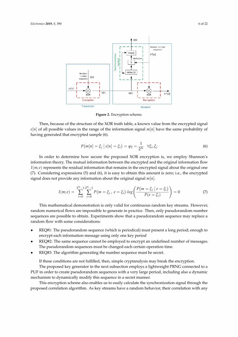
Figure 6. (a) Elemental EB device; (b) EB device with magnetic core (bilayer material) and separate field sensor.
In order to challenge (excite) the EB material, the field-generator coil produces a magnetic field 𝐻 with two components: a great continuous component 𝐻 and a variable field with time (10). The great continuous component is required by EB devices to operate, and the variable field is the challenge to the PUF. 𝐻 = 𝐻 + ℎ 𝑒 (10)
Generating controlled magnetic fields is quite complicated, especially in resource constrained nodes, but using an electrical (current) signal I (11) and the field-generator coil, the required magnetic field (10) may be produced. 𝐼 = 𝐼 + 𝑖 𝑒 (11)
The field that is generated in the coil will have a frequential composition that will be equal, as is evident, to the frequential composition of the signal in the excitation current. Thus, the material is subjected to a variable magnetic field and a variable magnetic flux will pass through it. This flow will induce an electromotive force in the sensing coil that will be measured and acquired to create the PUF response, as seen later.
This excitation will generate a magnetization (12) in the material, M, where 𝑀 is the saturation magnetization at room temperature and 𝑚 is the corresponding RF component. Hereinafter, in order to mathematically demonstrate the unclonable behavior of these EB devices, we are considering the superposition theorem to study each one of the frequential components ω in the magnetization and magnetic fields separately (13). 𝑀 = 𝑀 + 𝑚 𝑒 (12) 𝑀 = 𝑀 + 𝑚 𝑒 (13)
The relation between the magnetic field and the magnetization may take different forms (14). However, in EB devices (see Section 3.3.1), the magnetic material (analyzed on a macroscopic scale) is divided around domains with a magnetization 𝑀 when an external continuous magnetic field 𝐻 is applied in such a way that it can be said that each domain precesses inside the material around the
Figure 6. (a) Elemental EB device; (b) EB device with magnetic core (bilayer material) and separatefield sensor.
In order to challenge (excite) the EB material, the field-generator coil produces a magnetic field Hwith two components: a great continuous component Ho and a variable field with time (10). The greatcontinuous component is required by EB devices to operate, and the variable field is the challenge tothe PUF.
H = Ho + ∑k
h ejωkt (10)
Generating controlled magnetic fields is quite complicated, especially in resource constrainednodes, but using an electrical (current) signal I (11) and the field-generator coil, the required magneticfield (10) may be produced.
I = Io + ∑k
i ejωkt (11)
The field that is generated in the coil will have a frequential composition that will be equal, as isevident, to the frequential composition of the signal in the excitation current. Thus, the material issubjected to a variable magnetic field and a variable magnetic flux will pass through it. This flow willinduce an electromotive force in the sensing coil that will be measured and acquired to create the PUFresponse, as seen later.
This excitation will generate a magnetization (12) in the material, M, where Mo is the saturationmagnetization at room temperature and m is the corresponding RF component. Hereinafter, in orderto mathematically demonstrate the unclonable behavior of these EB devices, we are considering thesuperposition theorem to study each one of the frequential componentsωk in the magnetization andmagnetic fields separately (13).
M = Mo + ∑k
m ejωkt (12)
M = Mo + m ejωt (13)
The relation between the magnetic field and the magnetization may take different forms (14).However, in EB devices (see Section 3.3.1), the magnetic material (analyzed on a macroscopic scale) isdivided around domains with a magnetization M when an external continuous magnetic field Ho isapplied in such a way that it can be said that each domain precesses inside the material around the

Electronics 2019, 8, 390 11 of 22
axis of application of the magnetic field. Using the equation describing this movement, a new relationbetween the magnetic field and magnetization is deducted (15).
M =
(µ
µ0− 1)
H (14)
dMdt
= −γµo M× Ho (15)
Where µ is the magnetic permeability in the material (considered isotropic), µ0 is the magneticpermeability of free space, and γ is a gyromagnetic ratio. This ratio describes the relation between thespin magnetic moment in the material, µB, which is the moment that an electron spinning has on itself;and the kinetic moment that the electron has in the opposite direction, that will be named p (16).
γ = −µBp
(16)
In all of these expressions, the permeability and gyromagnetic parameters depend on the electronicconfiguration of the constituent atoms of the magnetic material, as well as on the interaction thatexists between them. Both parameters are then, in practice, unclonable and are the basis for theproposed PUF.
In order to create a PUF, the EB devices must respond to the applied challenge or excitation.In magnetic material, this response is the magnetic induction (17); where
=µ is a tensor describing the
magnetic permeability in the EB device (which is an anisotropic device, composed by two layers).
B ==µH (17)
In order to determine how variable the behavior of an EB device is, the value of this tensor mustbe studied. In particular, considering a second definition of the magnetic induction depending on themagnetic field and the magnetization vector (18), it can be deducted this tensor is the Polder tensor(19) and (20).
B = µ0(
H + M)
(18)
=µ = µo
µp −jK 0jK µp 00 0 1
(19)
µp = 1 +ωoωM
ω2o −ω2 K = −ω−ωM
ω2o −ω2 (20)
The Polder tensor describes, in general, the magnetic permeability of ferrites, but in this case,it may be also employed for EB devices. Two relevant parameters are identified (21): the Larmorfrequency ωo and a new parameter ωM dependent on the atomic structure of the material (i.e.,the magnetization vector).
γµo Ho = ωo
γµo M = ωM(21)
Although the Lamor frequency may be controlled through the excitation current generatingthe excitation magnetic field Ho; the ‘natural frequency’ ωM (in fact, a resonance frequency, seeSection 3.3.3) is uncontrollable and unclonable [45]. Besides, because of the EB effect (see Section 3.3.1)the magnetization vector induced in the device varies with time (depending on the logarithmof the time instant). Then, ωM will also evolve with time in an autonomous, independent, anduncontrollable manner.
Nowadays, however, there are no instruments or procedures to predict, manipulate, or clone thebehavior of this ‘natural frequency’ ωM or the EB devices (as it depends on atomic structures) [45].

Electronics 2019, 8, 390 12 of 22
In fact, in order to create two identical EB devices, a unique magnetic material must be firstly activatedand, later, divided into two samples. Besides, any attempt to extract or manipulate the PUF from itscasing and operation conditions will modify the magnetization vector and, in consequence, the systembehavior, the generated seed and, finally, the secret key stream.
However, before ensuring REQ#3 is fulfilled, it must be evaluated how variations inωM affectthe PUF responses. Figure 7 shows the evolution in µp and K depending on the excitation frequencyfor different possible values ofωM.
Electronics 2018, 7, x FOR PEER REVIEW 12 of 23
from its casing and operation conditions will modify the magnetization vector and, in consequence, the system behavior, the generated seed and, finally, the secret key stream.
However, before ensuring REQ#3 is fulfilled, it must be evaluated how variations in ω affect the PUF responses. Figure 7 shows the evolution in μ and 𝐾 depending on the excitation frequency for different possible values of ω .
Figure 7. Schematic representation of two possible work zones for the presented EB device.
As can be seen, the response of μ and 𝐾 is similar for all material around the Larmor frequency 𝜔 , regardless of the value of 𝜔 . Besides, the same situation occurs for very high or very low frequencies. Then, we will configure the device to work around high frequencies relatively far from the Larmor pulsation. This means that none of the previous terms tend to infinity and, in addition, the term 𝜔 influences the frequency behavior of the material (see Figure 7).
Finally, it is necessary to acquire or sense the magnetic induction to generate an analog electrical signal. As variable components are always considered in the fields, it is easy to generate that electrical (voltage) signal through an induced electromotive force in a second copper coil (22). ℰ = 𝐸 · 𝑑𝑙 = 𝑁𝐵 · 𝑛𝑑𝐴 = 𝑁𝐵 𝑑𝐴 = − 𝑑𝜙𝑑𝑡 (22)
With the previous expressions and discussions, it is demonstrated that there is a direct relationship between the magnetization of the material and its behavior as a transmission line for radio frequency signals. Then, as (nowadays) magnetization in EB devices is uncontrollable and unclonable (no work has reported a method to control the natural frequency 𝜔 )[45], the response of these devices as a transmission line to the applied excitation (challenge) will also be unclonable. REQ#3 is then met.
Then, to create a cipher and decipher pair, an EB material must be generated, divided into two identical samples; and using these samples, two EB devices are constructed. The same process must be repeated to build all required EB devices for both the cipher and the decipher.
3.3.3. Global Behavior and Seed Obtention
Previous equations establish a clear relationship between the components of the permeability tensor and the resonance frequencies of EB devices. In fact, a simple analysis shows that the EB device’s resonance frequency (that for which all reactive or imaginary components in μ are vanish) is the ‘natural frequency’, 𝜔 .
As in any other resonant system, at this resonance frequency, an EB device stores (or consumes) all received energy, so no signal or magnetic induction is transmitted. Then, each one of the EB devices will have the resonance at 𝑓 = (the particular value will depend of the atomic structure of the material) and will filter any signal within this bandwidth, known as notch band (see Figure 8).
Figure 7. Schematic representation of two possible work zones for the presented EB device.
As can be seen, the response of µp and K is similar for all material around the Larmor frequencyωo, regardless of the value of ωM. Besides, the same situation occurs for very high or very lowfrequencies. Then, we will configure the device to work around high frequencies relatively far fromthe Larmor pulsation. This means that none of the previous terms tend to infinity and, in addition,the term ωM influences the frequency behavior of the material (see Figure 7).
Finally, it is necessary to acquire or sense the magnetic induction to generate an analog electricalsignal. As variable components are always considered in the fields, it is easy to generate that electrical(voltage) signal through an induced electromotive force in a second copper coil (22).
ε =∮
CE·dl =
∫S
NB·ndA =∫
SNBndA = −dφm
dt(22)
With the previous expressions and discussions, it is demonstrated that there is a direct relationshipbetween the magnetization of the material and its behavior as a transmission line for radio frequencysignals. Then, as (nowadays) magnetization in EB devices is uncontrollable and unclonable (no workhas reported a method to control the natural frequency ωM) [45], the response of these devices as atransmission line to the applied excitation (challenge) will also be unclonable. REQ#3 is then met.
Then, to create a cipher and decipher pair, an EB material must be generated, divided into twoidentical samples; and using these samples, two EB devices are constructed. The same process must berepeated to build all required EB devices for both the cipher and the decipher.
3.3.3. Global Behavior and Seed Obtention
Previous equations establish a clear relationship between the components of the permeabilitytensor and the resonance frequencies of EB devices. In fact, a simple analysis shows that the EBdevice’s resonance frequency (that for which all reactive or imaginary components in
=µ are vanish) is
the ‘natural frequency’, ωM.As in any other resonant system, at this resonance frequency, an EB device stores (or consumes)
all received energy, so no signal or magnetic induction is transmitted. Then, each one of the EB deviceswill have the resonance at fM = ωM
2π (the particular value will depend of the atomic structure of thematerial) and will filter any signal within this bandwidth, known as notch band (see Figure 8).

Electronics 2019, 8, 390 13 of 22
Electronics 2018, 7, x FOR PEER REVIEW 13 of 23
Figure 8. Frequential response of an EB device.
On the other hand, this resonance frequency will vary with time (as already said), with a speed 𝑣 . Experimental studies [45], besides, prove this frequency evolves in downward direction (see Figure 8).
Then, the global PUF proposed in Figure 4 will present a global frequential response calculated as the superposition of 𝑁 notch filters, one for each EB device (see Figure 9). Mathematically, then, when applying a challenge 𝑐ℎ(𝑡) , a response 𝑟𝑝(𝑡) is obtained whose frequential structure is variable and unclonable (23), as the natural frequency 𝜔 cannot be controlled [45]. 𝑐ℎ(𝑡) = 𝐶 e
𝑟𝑝(𝑡) = 𝑃𝑈𝐹 𝑐ℎ(𝑡) = 𝐴 (𝑡)𝐶 e
(23)
Figure 9. Operation of the complete PUF.
However, to maintain EB devices in the operation conditions, challenges must be mixed with great continuous signals, to create the required continuous magnetic fields. Then, the obtained response will also be mixed with the great signal which must be removed to extract the real PUF response. To perform this operation, in the proposed PUF (see Figure 4) a non-EB device and a lock-in are included.
The non-EB device has the two windings described above and the core is composed of either a bilayer material where the exchange-bias has not been activated and has the initial permeability value) or is an air core (vacuum). The objective of using this core is to isolate the effect on the phase shift of the signal due to the effect of the couplings that may exist in the windings and which, being identical to those that are mounted in the devices with the activated bilayer core, introduce a similar phase shift. In this way, the two signals that enter the lock-in are differentiated only due to the effect generated by the exchange-bias phenomenon.
Figure 8. Frequential response of an EB device.
On the other hand, this resonance frequency will vary with time (as already said), with a speed vM.Experimental studies [45], besides, prove this frequency evolves in downward direction (see Figure 8).
Then, the global PUF proposed in Figure 4 will present a global frequential response calculatedas the superposition of Nd notch filters, one for each EB device (see Figure 9). Mathematically, then,when applying a challenge ch(t), a response rp(t) is obtained whose frequential structure is variableand unclonable (23), as the natural frequency ωM cannot be controlled [45].
ch(t) = ∑k
Ck ejωkt
rp(t) = PUF{ch(t)} =Nd∑
s=1∑k
As(t)Ck ejωkt(23)
Electronics 2018, 7, x FOR PEER REVIEW 13 of 23
Figure 8. Frequential response of an EB device.
On the other hand, this resonance frequency will vary with time (as already said), with a speed 𝑣 . Experimental studies [45], besides, prove this frequency evolves in downward direction (see Figure 8).
Then, the global PUF proposed in Figure 4 will present a global frequential response calculated as the superposition of 𝑁 notch filters, one for each EB device (see Figure 9). Mathematically, then, when applying a challenge 𝑐ℎ(𝑡) , a response 𝑟𝑝(𝑡) is obtained whose frequential structure is variable and unclonable (23), as the natural frequency 𝜔 cannot be controlled [45]. 𝑐ℎ(𝑡) = 𝐶 e
𝑟𝑝(𝑡) = 𝑃𝑈𝐹 𝑐ℎ(𝑡) = 𝐴 (𝑡)𝐶 e
(23)
Figure 9. Operation of the complete PUF.
However, to maintain EB devices in the operation conditions, challenges must be mixed with great continuous signals, to create the required continuous magnetic fields. Then, the obtained response will also be mixed with the great signal which must be removed to extract the real PUF response. To perform this operation, in the proposed PUF (see Figure 4) a non-EB device and a lock-in are included.
The non-EB device has the two windings described above and the core is composed of either a bilayer material where the exchange-bias has not been activated and has the initial permeability value) or is an air core (vacuum). The objective of using this core is to isolate the effect on the phase shift of the signal due to the effect of the couplings that may exist in the windings and which, being identical to those that are mounted in the devices with the activated bilayer core, introduce a similar phase shift. In this way, the two signals that enter the lock-in are differentiated only due to the effect generated by the exchange-bias phenomenon.
Figure 9. Operation of the complete PUF.
However, to maintain EB devices in the operation conditions, challenges must be mixed with greatcontinuous signals, to create the required continuous magnetic fields. Then, the obtained response willalso be mixed with the great signal which must be removed to extract the real PUF response. To performthis operation, in the proposed PUF (see Figure 4) a non-EB device and a lock-in are included.
The non-EB device has the two windings described above and the core is composed of either abilayer material where the exchange-bias has not been activated and has the initial permeability value)or is an air core (vacuum). The objective of using this core is to isolate the effect on the phase shift ofthe signal due to the effect of the couplings that may exist in the windings and which, being identicalto those that are mounted in the devices with the activated bilayer core, introduce a similar phase shift.In this way, the two signals that enter the lock-in are differentiated only due to the effect generated bythe exchange-bias phenomenon.
The lock-in amplifier is often a device that returns a DC signal proportional to the phase shiftbetween two signals and to the amplitude of both signals. Therefore, if the same signal flows throughtwo different paths, the differences in the circuitry of these paths will be what cause the changes in thesignal and the difference that the lock-in will measure.
At this point, then, an unclonable and dynamic PUF response to the applied challenge is obtained.

Electronics 2019, 8, 390 14 of 22
The output signal of the lock-in goes through a post-processing system that measures it andconverts it into a valid seed. The output seed of that unit will be the result of a mathematical operationthat relates the amplitude of the received signal and its frequency; and therefore, will depend as muchon the state of the cores of material bilayer with the effect of exchange-bias developing over time,as the set of signal frequencies that will be introduced into the material (challenge).
Complex algorithms to control the challenge to be applied or the seed calculation could beemployed in order to increase the global entropy of the key generator. However, for this initial workpresenting the solution, we are considering as challenge a simple composition of Nc harmonics; and theseed calculation was based on a sampling scheme (a sigma-delta modulator) to extract from the analogsignal three digital words with the appropriate length. Besides, in order to remove transitory responsesand other exogenous effects affecting the seed calculation, the post-processing module was configuredto only respond to long-term changes in PUF response. Moving average filters are implemented toperform this function. This technological feature might limit the randomness of the generated keys,but the use of PRNG prevents this problem.
4. Performance Evaluation and Results
In relation to the proposed solution, an evaluation focused on security analyses has no sense,as the final obtained security level is directly dependent on the Trifork PRNG, a technology that hasalready been validated [40]. On the other hand, a qualitative risk analysis is not relevant at this point,as previous discussions have already proved that most relevant security risks have been addressed.Therefore, for this work, we are proposing an experimental validation based on a performanceevaluation and key performance indicators (KPI).
4.1. Experiment Description
Five different experiments were carried out in order to evaluate five basic indicators:(1) randomness level; (2) the bit error rate depending on the accumulated operation time; (3) thedistance between key streams generated by a similar PUF; (4) the malfunction probability dependingon the number of EB devices in the PUF; and (5) the resource consumption caused by the proposedencryption scheme.
The first four parameters are going to be evaluated with experiments based on simulationscenarios and tools. The last and fifth KPI is evaluated using a real implementation.
Simulation scenarios were built using the MATLAB and SimuLink software tools, which alsoinclude mechanisms for electromagnetic and engineering simulations. It is a proprietary suite thatemploys a specific programming language based on C syntaxis. However, libraries based on othertechnologies such as C or Java may be employed. This suite was deployed in a Linux (Ubuntu 16.04)machine with 8GB of RAM memory and an Intel i7 processor.
The simulation scenario consisted of two nodes creating a bidirectional communication linkbetween them (see Figure 1). Models for magnetic materials, radio channels, magnetization vectors, etc.,were taken from standard existing libraries. The simulation model for the EB devices was configuredand characterized through numerical functions fitted to follow and behave as the measures obtainedby Migliorini and other authors [45] indicate. Apart from the magnetic components, each node wasconstructed with a relatively small amount of hardware: a general-purpose embedded processor withanalog-digital converters, 5 kilobits of SRAM and 32 kilobytes of DRAM.
In order to pack and assign the described resources to the nodes, virtual containers were employed.In particular, Kernel-based Virtual Machine (KVM) technologies were employed with the libVirtApplication Programming Interface (API). In that way, a simple C++ program may be employed tocontrol virtual instances and they may be managed from the MATLAB suite.
With the objective of connecting the virtual instances and the MATLAB suite where the simulationscenario runs, the bridges provided by the MATLAB and Simulink libraries are deployed and executed.
Electronics 2019, 8, 390 15 of 22
These bridges forward the input traffic in the simulated nodes to the external virtual machine, so realalgorithms, solutions, and protocols may be easily tested.
In the first four experiments, simulation tools are adequate to provide relevant results as thelimitations due to hardware issues are not evaluated (we are considering nodes can easily implementthe proposed cipher). In the last experiment, hardware limitations were considered and real deviceswere employed.
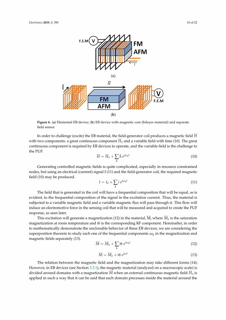
For the first experiment, the NIST SP 800-22 test suite [46] was considered. This suite includes15 tests that are usually employed to evaluate the randomness of key generators, PUFs, and othersimilar proposals. These tests consider two parameters (usually known as α and p) to determine if theevaluated number sequence is random. Basically, the tests evaluate if a sequence is random with aconfidence equal to (1− α). Tests obtain the p-value and they are successful (the sequence is random)if it is greater than α. In our experiment we are considering α = 0.01. The simulation scenario consistedof the proposed key generator where 64 different EB devices where integrated.
For the second experiment, a collection of different simulations was carried out. For each differentsimulation, the number of EB devices in the proposed PUF was increased. A bidirectional securecommunication link is stablished between both the transmitter and the receiver for each configuration.As a supporting wireless communication module, we have selected a Bluetooth 4.0 technology solution(available in the NS3 libraries). Communication links were configured to be 10Mbps links (Bluetooth4.0 enables up to 32 Mbps connections). Using these links, 100 information packets per second weretransmitted. Each packet was configured to have 100 information bits. Time was divided into 5-h slots.In this time period, Npackets = 1.8× 10⁶ packets (or Nbits = 1.8× 10⁹ information bits) are transmitted.Then, the resulting amounts are enough to evaluate the bit error rate (BER). Thus, the BER in thestablished communication link was evaluated and measured for each different slot.
The third experiment was performed using a simulation scenario similar to the previous one.Nevertheless, in this case, for each PUF configuration, cipher and decipher were built using ‘cloned’PUF. The similarity level between PUF and the resulting key streams are measured and evaluated.
For these three initial experiments, simulations considering PRNG were configured as follows:N = 16 to represent a common current situation; and the applied excitation (challenge) to the PUFconsisted of a composition of 100 harmonics whose frequencies were calculated using an automaticalgorithm (24).
fk = 1000·2k3
(24)
Later, in the fourth experiment, some modifications in the scenario were applied. The cipherand decipher were reconsidered to implement two identical PUF (two samples from a unique EBactivated material). The probability of the cipher and decipher not being able to operate correctly dueto malfunctions in the PUF is then evaluated. Different configurations and numbers of EB devices inthe PUF were considered. With this experiment, the probability of a magnetic material so anisotropicthat two samples from the same material do not behave in the same manner is analyzed. The sameconfiguration parameters were employed in this fourth experiment for the cipher and the decipher.
Simulations for these fourth initial experiments were repeated 12 times for each case.Each simulation was configured to represent 360 h of operation.
The fifth and last experiment was completely different from all already described. With theobjective of evaluating the effect of hardware limitations, especially in the context of CPS whereresource constrained devices are usually employed, in the proposed architecture; a real implementationof the proposed solution was executed. We evaluated the consumption in terms of RAM memory,program space, and computational time. The experiment was repeated for different values of N (thebit-length of number in the PRNG).
As a hardware platform, we employed an Arduino Nano board. It includes an AVRmicrocontroller, the ATmega328 microcontroller. It also has 32 KB of flash memory, 2 KB of SRAMmemory, and 1 KB of EEPROM (which is rarely employed).
Electronics 2019, 8, 390 16 of 22
The implemented PUF for this experiment was manufactured as indicated by Migliorini [45].Four different EB devices were employed in the designed PUF.
4.2. Results
In this section, results of the described experiments in the previous section are presentedand discussed.
In order to remove from the simulation results (as much as possible) fluctuations in the simulationexecution process caused by exogenous variables (e.g., delays operations performed by the operatingsystems), the average of all obtained results from the 12 performed simulation repetitions are employedto calculate the final results.
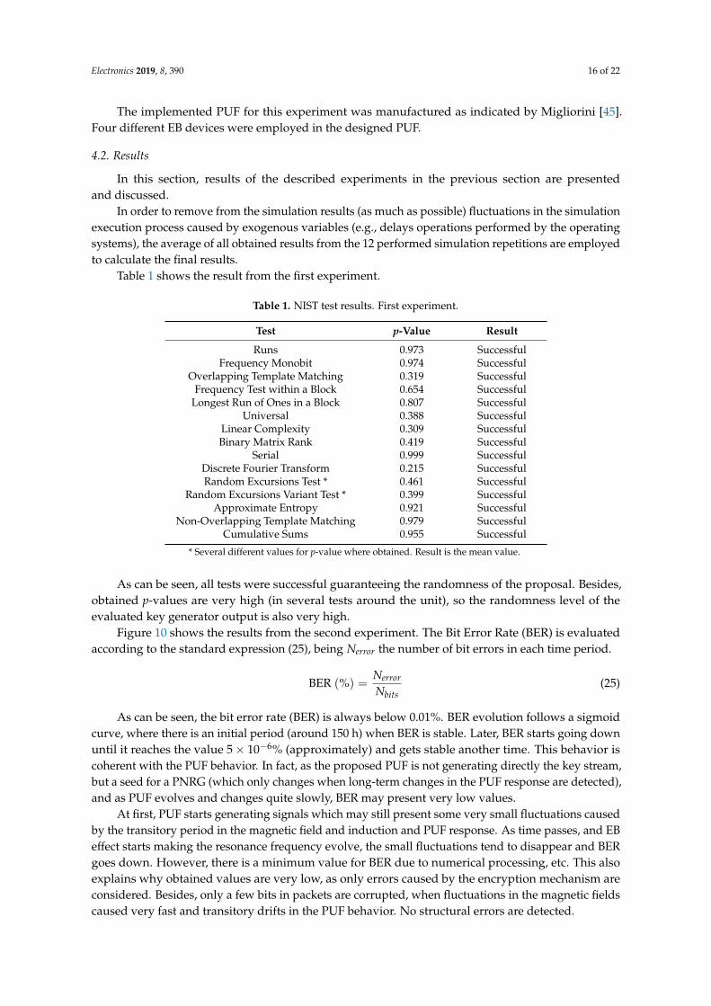
Table 1 shows the result from the first experiment.
Table 1. NIST test results. First experiment.
Test p-Value Result
Runs 0.973 SuccessfulFrequency Monobit 0.974 Successful
Overlapping Template Matching 0.319 SuccessfulFrequency Test within a Block 0.654 Successful
Longest Run of Ones in a Block 0.807 SuccessfulUniversal 0.388 Successful
Linear Complexity 0.309 SuccessfulBinary Matrix Rank 0.419 Successful
Serial 0.999 SuccessfulDiscrete Fourier Transform 0.215 SuccessfulRandom Excursions Test * 0.461 Successful
Random Excursions Variant Test * 0.399 SuccessfulApproximate Entropy 0.921 Successful
Non-Overlapping Template Matching 0.979 SuccessfulCumulative Sums 0.955 Successful
* Several different values for p-value where obtained. Result is the mean value.
As can be seen, all tests were successful guaranteeing the randomness of the proposal. Besides,obtained p-values are very high (in several tests around the unit), so the randomness level of theevaluated key generator output is also very high.
Figure 10 shows the results from the second experiment. The Bit Error Rate (BER) is evaluatedaccording to the standard expression (25), being Nerror the number of bit errors in each time period.
BER (%) =Nerror
Nbits(25)
As can be seen, the bit error rate (BER) is always below 0.01%. BER evolution follows a sigmoidcurve, where there is an initial period (around 150 h) when BER is stable. Later, BER starts going downuntil it reaches the value 5× 10⁻⁶% (approximately) and gets stable another time. This behavior iscoherent with the PUF behavior. In fact, as the proposed PUF is not generating directly the key stream,but a seed for a PNRG (which only changes when long-term changes in the PUF response are detected),and as PUF evolves and changes quite slowly, BER may present very low values.
At first, PUF starts generating signals which may still present some very small fluctuations causedby the transitory period in the magnetic field and induction and PUF response. As time passes, and EBeffect starts making the resonance frequency evolve, the small fluctuations tend to disappear and BERgoes down. However, there is a minimum value for BER due to numerical processing, etc. This alsoexplains why obtained values are very low, as only errors caused by the encryption mechanism areconsidered. Besides, only a few bits in packets are corrupted, when fluctuations in the magnetic fieldscaused very fast and transitory drifts in the PUF behavior. No structural errors are detected.

Electronics 2019, 8, 390 17 of 22Electronics 2018, 7, x FOR PEER REVIEW 17 of 23
Figure 10. Results from the second experiment.
As can be seen, the bit error rate (BER) is always below 0.01%. BER evolution follows a sigmoid curve, where there is an initial period (around 150 hours) when BER is stable. Later, BER starts going down until it reaches the value 5 × 10 % (approximately) and gets stable another time. This behavior is coherent with the PUF behavior. In fact, as the proposed PUF is not generating directly the key stream, but a seed for a PNRG (which only changes when long-term changes in the PUF response are detected), and as PUF evolves and changes quite slowly, BER may present very low values.
At first, PUF starts generating signals which may still present some very small fluctuations caused by the transitory period in the magnetic field and induction and PUF response. As time passes, and EB effect starts making the resonance frequency evolve, the small fluctuations tend to disappear and BER goes down. However, there is a minimum value for BER due to numerical processing, etc. This also explains why obtained values are very low, as only errors caused by the encryption mechanism are considered. Besides, only a few bits in packets are corrupted, when fluctuations in the magnetic fields caused very fast and transitory drifts in the PUF behavior. No structural errors are detected.
On the other hand, it can be also seen, as the number of EB devices in the PUF is increased, the initial BER is also higher. In fact, as more different magnetic materials are considered, the power and energy associated to fluctuations in magnetic materials are also higher. Consequently, more errors are induced. In any case, the obtained BER values are similar to those associated to traditional encryption and communication systems [47].
It is important to note that, contrary to other works where real implementations are employed to evaluate BER [34], in this case we are using a simulation scenario where only some effects are considered (in particular, only effects related to EB phenomenon are analyzed). For example, fluctuations in the electrical challenges are not considered. Thus, results with real devices might strongly change (BER may go up several magnitude orders) and advanced techniques, such as error correction modules, could be necessary.
Figure 11 shows the results of the third experiment. Distances between key streams are calculated using a statistical expression. In particular, this distance is defined as the mutual information between both key streams (a similar understating to which employed in context-tree weighting method [48]). Mutual information is null when both streams are statistically independent and equal to 𝑁 (the number of bits per sample, see Section 3), when they are statistically equivalent. To normalize the mutual information, ranging between zero and 𝑁, and turn this function into a distance function a simple algebraic expression is employed (26). This definition guarantees two streams that are 100% different are statistically independent, contrary to traditional (Euclidean) distance definitions.
Figure 10. Results from the second experiment.
On the other hand, it can be also seen, as the number of EB devices in the PUF is increased,the initial BER is also higher. In fact, as more different magnetic materials are considered, the powerand energy associated to fluctuations in magnetic materials are also higher. Consequently, moreerrors are induced. In any case, the obtained BER values are similar to those associated to traditionalencryption and communication systems [47].
It is important to note that, contrary to other works where real implementations are employedto evaluate BER [34], in this case we are using a simulation scenario where only some effectsare considered (in particular, only effects related to EB phenomenon are analyzed). For example,fluctuations in the electrical challenges are not considered. Thus, results with real devices mightstrongly change (BER may go up several magnitude orders) and advanced techniques, such as errorcorrection modules, could be necessary.
Figure 11 shows the results of the third experiment. Distances between key streams are calculatedusing a statistical expression. In particular, this distance is defined as the mutual information betweenboth key streams (a similar understating to which employed in context-tree weighting method [48]).Mutual information is null when both streams are statistically independent and equal to N (the numberof bits per sample, see Section 3), when they are statistically equivalent. To normalize the mutualinformation, ranging between zero and N, and turn this function into a distance function a simplealgebraic expression is employed (26). This definition guarantees two streams that are 100% differentare statistically independent, contrary to traditional (Euclidean) distance definitions.
d(k; k∗) =N − I(k; k∗)
N(26)
Distance between the manufacturing conditions of two PUF is evaluated using a Euclideandistance and the notion of mean square error. Being C1 and C2 vectors describing the manufacturingconditions (M variables), the distance between the two corresponding PUF may be directlyobtained (27).
d(C1; C2) =1M
√√√√ M
∑i=1
(C1(i)− C2(i))2 (27)

Electronics 2019, 8, 390 18 of 22
Electronics 2018, 7, x FOR PEER REVIEW 18 of 23
𝑑(𝑘; 𝑘∗) = 𝑁 − 𝐼(𝑘; 𝑘∗) 𝑁 (26)
Distance between the manufacturing conditions of two PUF is evaluated using a Euclidean distance and the notion of mean square error. Being 𝐶 and 𝐶 vectors describing the manufacturing conditions (𝑀 variables), the distance between the two corresponding PUF may be directly obtained (27).
𝑑(𝐶 ; 𝐶 ) = 1𝑀 𝐶 (𝑖) − 𝐶 (𝑖) (27)
Figure 11. Results from the third experiment.
As can be seen, even two PUFs manufactured as ‘clones’ generate key streams that are 50% different. In other words, and considering the distance between key streams is evaluated using the mutual information, only half of bits per sample in the key streams are statistically independent. For configurations including more than two EB devices, even PUFs manufactured with only 10% difference generate statistically independent key streams (distance 100%). Configurations including only one or two EB devices also generate independent key streams and secure encryptions (as only identical key streams may grant access to the private information).
However, similar PUFs generate dependent key streams if fewer EB devices are included. Even if as more different PUFs are manufactured the distance between key streams also increases, one-device configurations only produce totally independent key streams for totally different PUFs; while two-device configuration required materials with at least 50% differences.
Any case, this experiment validates the unclonable behavior of the proposed PUF and encryption solution.
Figure 12 shows the results of the fourth experiment.
Figure 11. Results from the third experiment.
As can be seen, even two PUFs manufactured as ‘clones’ generate key streams that are 50%different. In other words, and considering the distance between key streams is evaluated using themutual information, only half of bits per sample in the key streams are statistically independent.For configurations including more than two EB devices, even PUFs manufactured with only 10%difference generate statistically independent key streams (distance 100%). Configurations includingonly one or two EB devices also generate independent key streams and secure encryptions (as onlyidentical key streams may grant access to the private information).
However, similar PUFs generate dependent key streams if fewer EB devices are included.Even if as more different PUFs are manufactured the distance between key streams also increases,one-device configurations only produce totally independent key streams for totally different PUFs;while two-device configuration required materials with at least 50% differences.
Any case, this experiment validates the unclonable behavior of the proposed PUF andencryption solution.
Figure 12 shows the results of the fourth experiment.Electronics 2018, 7, x FOR PEER REVIEW 19 of 23
Figure 12. Results from the fourth experiment.
As Figure 12 shows, the malfunction probability is also higher as more EB devices are employed to build the PUF. In fact, as more identical EB devices must be manufactured, the malfunction probability grows up. In any case, above 𝑁 = 16 , configurations present a stable malfunction probability around 0,01%. Between 𝑁 = 1 and 𝑁 = 16 , the malfunction probability goes up exponentially, being 10 % the minimum probability (for a one EB device configuration).
With the four previously described experiments, the performance of the PUF is evaluated. However, one final experiment is required to evaluate indicators related to hardware nodes and limitations.
Table 2 shows the obtained results from the fifth experiment.
Table 2. Resource consumption. Results from the fifth experiment. 𝑵 Use of RAM Use of program space Processing time to generate the first
key sample 4 12% 65% 120 𝜇s 8 14% 67% 3.9 𝑚s
10 14% 67% 5 𝑚s 12 14% 67% 5 𝑚s 16 14% 67% 5 𝑚s
As can be seen, results are almost independent from the sample length (𝑁). In general, the proposed solution consumes around 70% of available program space in resource constrained nodes. Although this amount may seem too high, the remaining 30% is enough to implement sensing algorithms and other similar small software solutions.
On the other hand, the consumed processing time is quite low, so sampling algorithms can be easily implemented. Considering the required time to encrypt one sample, the fastest signal our nodes could sample is 200 KHz. Traditionally, an Arduino board may consider an analog signal with a maximum bandwidth up to 4.5 MHz. When using our cipher, this quantity is reduced to 200 KHz, but this speed is still enough for most applications.
Once the proposed solution is proven to be adequate for implementation in resource constrained nodes, we can compare resource consumption in our proposal to previously reported solutions. Table 3 shows that comparison.
Figure 12. Results from the fourth experiment.
As Figure 12 shows, the malfunction probability is also higher as more EB devices are employed tobuild the PUF. In fact, as more identical EB devices must be manufactured, the malfunction probability
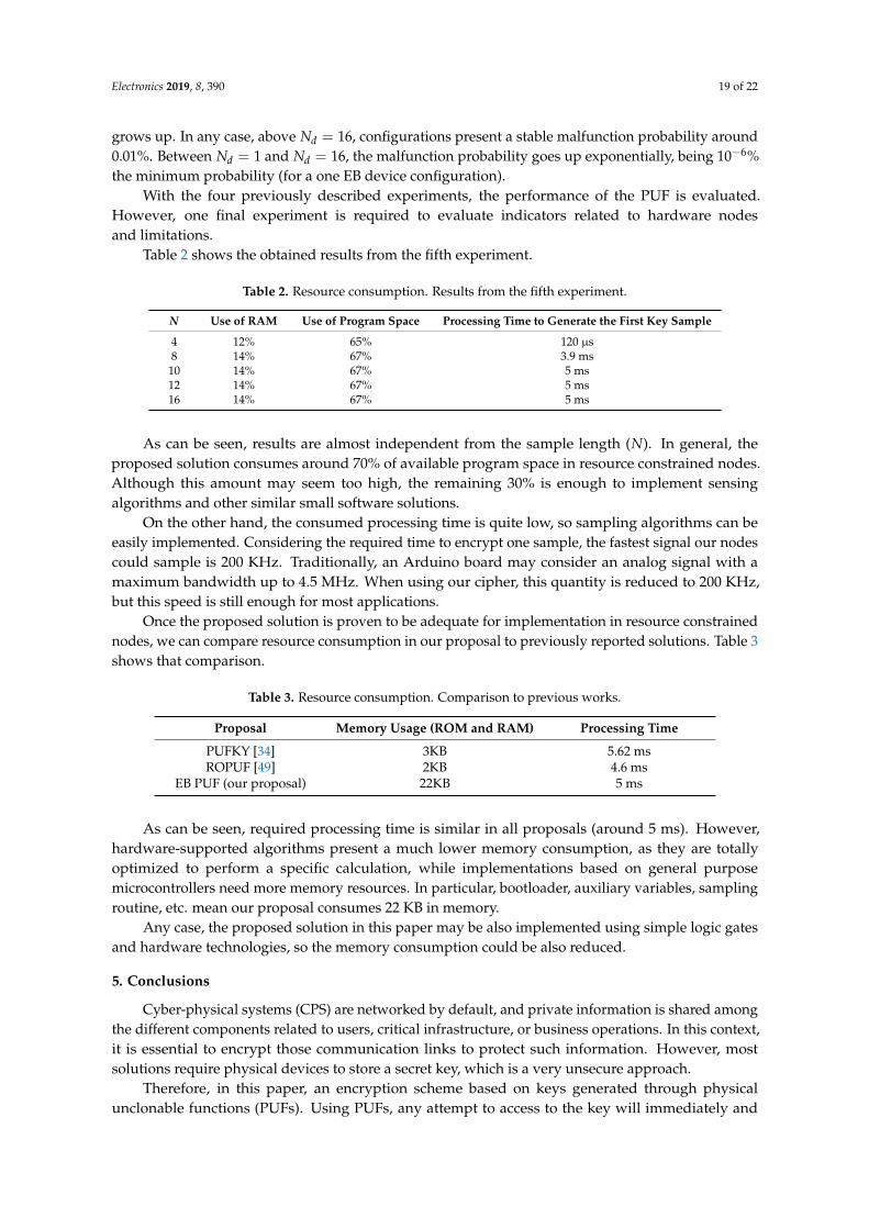
Electronics 2019, 8, 390 19 of 22
grows up. In any case, above Nd = 16, configurations present a stable malfunction probability around0.01%. Between Nd = 1 and Nd = 16, the malfunction probability goes up exponentially, being 10−6%the minimum probability (for a one EB device configuration).
With the four previously described experiments, the performance of the PUF is evaluated.However, one final experiment is required to evaluate indicators related to hardware nodesand limitations.
Table 2 shows the obtained results from the fifth experiment.
Table 2. Resource consumption. Results from the fifth experiment.
N Use of RAM Use of Program Space Processing Time to Generate the First Key Sample
4 12% 65% 120 µs8 14% 67% 3.9 ms10 14% 67% 5 ms12 14% 67% 5 ms16 14% 67% 5 ms
As can be seen, results are almost independent from the sample length (N). In general, theproposed solution consumes around 70% of available program space in resource constrained nodes.Although this amount may seem too high, the remaining 30% is enough to implement sensingalgorithms and other similar small software solutions.
On the other hand, the consumed processing time is quite low, so sampling algorithms can beeasily implemented. Considering the required time to encrypt one sample, the fastest signal our nodescould sample is 200 KHz. Traditionally, an Arduino board may consider an analog signal with amaximum bandwidth up to 4.5 MHz. When using our cipher, this quantity is reduced to 200 KHz,but this speed is still enough for most applications.
Once the proposed solution is proven to be adequate for implementation in resource constrainednodes, we can compare resource consumption in our proposal to previously reported solutions. Table 3shows that comparison.
Table 3. Resource consumption. Comparison to previous works.
Proposal Memory Usage (ROM and RAM) Processing Time
PUFKY [34] 3KB 5.62 msROPUF [49] 2KB 4.6 ms
EB PUF (our proposal) 22KB 5 ms
As can be seen, required processing time is similar in all proposals (around 5 ms). However,hardware-supported algorithms present a much lower memory consumption, as they are totallyoptimized to perform a specific calculation, while implementations based on general purposemicrocontrollers need more memory resources. In particular, bootloader, auxiliary variables, samplingroutine, etc. mean our proposal consumes 22 KB in memory.
Any case, the proposed solution in this paper may be also implemented using simple logic gatesand hardware technologies, so the memory consumption could be also reduced.
5. Conclusions
Cyber-physical systems (CPS) are networked by default, and private information is shared amongthe different components related to users, critical infrastructure, or business operations. In this context,it is essential to encrypt those communication links to protect such information. However, mostsolutions require physical devices to store a secret key, which is a very unsecure approach.
Therefore, in this paper, an encryption scheme based on keys generated through physicalunclonable functions (PUFs). Using PUFs, any attempt to access to the key will immediately and

Electronics 2019, 8, 390 20 of 22
irreversibly change the key, and given one PUF, even the manufacturer cannot clone it into an identicalone. The proposed key generator is based on magnetic materials to meet the low-cost and small sizerequirements of CPS. In particular, materials with an activated exchange-bias effect are employed,together with simple copper coils. The encryption process can be based on a simple XOR gate becauseof the robustness of the proposed key generator.
Results prove the unclonable behavior of the proposed PUF and the security level of the describedencryption scheme. On the other hand, the described solution also meets the requirements of resourceconstrained nodes in a CPS.
Author Contributions: The contributions described in this work are distributed among the authors as follows:All authors wrote the paper; M.P.-J. and A.M. contributed to the theoretical formalization; R.A. contributed to theproposal of the different simulation paradigms; and B.B. developed the global architecture and application model.
Funding: The research leading to these results has received funding from the Ministry of Economy andCompetitiveness through SEMOLA (TEC2015-68284-R) project and from the Ministry of Science, Innovation andUniversities through VACADENA (RTC-2017-6031-2) project.
Conflicts of Interest: The authors declare no conflict of interest.
References
1. Bordel, B.; Alcarria, R.; Robles, T.; Martín, D. Cyber–physical systems: Extending pervasive sensing fromcontrol theory to the Internet of Things. Pervasive Mob. Comput. 2017, 40, 156–184. [CrossRef]
2. Sánchez, B.B.; Alcarria, R.; de Rivera, D.S.; Sánchez-Picot, A. Enhancing Process Control in Industry 4.0Scenarios using Cyber-Physical Systems. JoWUA 2016, 7, 41–64.
3. Lee, E.A. Cyber-physical systems-are computing foundations adequate. In Proceedings of the Position Paperfor NSF Workshop on Cyber-Physical Systems: Research Motivation, Techniques and Roadmap, Austin, TX,USA, 16–17 October 2006; Volume 2, pp. 1–9.
4. Bordel, B.; Alcarria, R.; Jara, A. Process execution in humanized Cyber-physical systems: Soft processes.In Proceedings of the 12th Iberian Conference on Information Systems and Technologies (CISTI), Lisbon,Portugal, 21–24 June 2017; pp. 1–7.
5. Bordel, B.; Alcarria, R.; Sánchez-de-Rivera, D.; Robles, T. Protecting industry 4.0 systems against the maliciouseffects of cyber-physical attacks. In Proceedings of the International Conference on Ubiquitous Computingand Ambient Intelligence, Philadelphia, PA, USA, 7–10 November 2017; pp. 161–171.
6. Bordel, B.; Alcarria, R.; Robles, T.; Sánchez-Picot, Á. Stochastic and information theory techniques toreduce large datasets and detect cyberattacks in Ambient Intelligence Environments. IEEE Access 2018, 6,34896–34910. [CrossRef]
7. Ashibani, Y.; Mahmoud, Q.H. Cyber physical systems security: Analysis, challenges and solutions. Comput.Secur. 2017, 68, 81–97. [CrossRef]
8. Xu, Z.; Liu, X.; Zhang, G.; He, W.; Dai, G.; Shu, W. A certificateless signature scheme for mobile wirelesscyber-physical systems. In Proceedings of the 28th International Conference on Distributed ComputingSystems Workshops, ICDCS’08, Beijing, China, 17–20 June 2008; pp. 489–494.
9. Robles, T.; Bordel, B.; Alcarria, R.; Sánchez-de-Rivera, D. Blockchain Technologies for Private DataManagement in AmI Environments. Proceedings 2018, 2, 1230. [CrossRef]
10. Sánchez-de-Rivera, D.; Martín, D.; Alcarria, R.; Bordel, B.; Robles, T. Towards a Wireless and Low-PowerInfrastructure for Representing Information Based on E-Paper Displays. Sustainability 2017, 9, 76. [CrossRef]
11. Herder, C.; Yu, M.D.; Koushanfar, F.; Devadas, S. Physical unclonable functions and applications: A tutorial.Proc. IEEE 2014, 102, 1126–1141. [CrossRef]
12. Lai, X. On the Design and Security of Block Ciphers; Eidgenössische Technische Hochschule Zürich: Zürich,Switzerland, 1992.
13. Koopman, P.; Chakravarty, T. Cyclic redundancy code (CRC) polynomial selection for embedded networks.In Proceedings of the International Conference on Dependable Systems and Networks (DNS’04), Florence,Italy, 28 June–1 July 2004; pp. 145–154.
14. Martin, H.; Peris-Lopez, P.; Tapiador, J.E.; San Millan, E. An Estimator for the ASIC Footprint Area ofLightweight Cryptographic Algorithms. IEEE Trans. Ind. Inform. 2014, 10, 1216–1225. [CrossRef]

Electronics 2019, 8, 390 21 of 22
15. Bordel, B.; Orue, A.B.; Alcarria, R.; Sanchez-De-Rivera, D. An Intra-Slice Security Solution for Emerging 5GNetworks Based on Pseudo-Random Number Generators. IEEE Access 2018, 6, 16149–16164. [CrossRef]
16. Miller, V.S. Use of Elliptic Curves in Cryptography. In Advances in Cryptology—CRYPTO ’85 Proceedings;Lecture Notes in Computer Science; Springer: Berlin, Heidelberg, 1985; Volume 218.
17. Porambage, P.; Schmitt, C.; Kumar, P.; Gurtov, A.; Ylianttila, M. Two-phase authentication protocolfor wireless sensor networks in distributed IoT applications. In Proceedings of the 2014 IEEEWirelessCommunications and Networking Conference (WCNC’14), Istanbul, Turkey, 6–9 April 2014; pp. 2728–2733.
18. Vegh, L.; Miclea, L. Enhancing security in cyber-physical systems through cryptographic and steganographictechniques. In Proceedings of the 2014 IEEE International Conference on Automation, Quality and Testing,Robotics (AQTR), Cluj-Napoca, Romania, 22–24 May 2014; pp. 1–6.
19. Kogiso, K.; Fujita, T. Cyber-security enhancement of networked control systems using homomorphicencryption. In Proceedings of the 54th Annual Conference on Decision and Control (CDC), Osaka, Japan,15–18 December 2015; pp. 6836–6843.
20. Pohls, H.C. JSON Sensor Signatures (JSS): End-to-End Integrity Protection from Constrained Device to IoTApplication. In Proceedings of the 9th International Conference on Innovative Mobile and Internet Servicesin Ubiquitous Computing (IMIS’15), Blumenau, Brazil, 8–10 July 2015; pp. 306–312.
21. Yampolskiy, M.; Horváth, P.; Koutsoukos, X.D.; Xue, Y.; Sztipanovits, J. A language for describing attacks oncyber-physical systems. Int. J. Crit. Infrastruct. Prot. 2015, 8, 40–52. [CrossRef]
22. Mo, Y.; Kim, T.H.-J.; Brancik, K.; Dickinson, D.; Lee, H.; Perrig, A.; Sinopoli, B. Cyber–Physical Security of aSmart Grid Infrastructure. Proc. IEEE 2012, 100, 195–209.
23. Pasqualetti, F.; Dorfler, F.; Bullo, F. Cyber-physical attacks in power networks: Models, fundamentallimitations and monitor design. In Proceedings of the 50th IEEE Conference on Decision and Control,a European Control Conference (CDC-ECC’11), Orlando, FL, USA, 12–15 December 2011; pp. 2195–2201.
24. Sridhar, S.; Hahn, A.; Govindarasu, M. Cyber–Physical System Security for the Electric Power Grid. Proc. IEEE2012, 100, 210–224. [CrossRef]
25. Maes, R.; Verbauwhede, I. Physically Unclonable Functions: A Study on the State of the Art and Future ResearchDirections; Springer: Berlin, Heidelberg, 2010.
26. Gassend, B.; Clarke, D.; Van Dijk, M.; Devadas, S. Silicon physical random functions. In Proceedings of the9th ACM conference on Computer and communications security, Washington, DC, USA, 18–22 November2002; pp. 148–160.
27. Gassend, B.; Clarke, D.; Van Dijk, M.; Devadas, S. Controlled physical random functions. In Proceedings ofthe 18th Annual Computer Security Applications Conference, Las Vegas, NV, USA, 9–13 December 2002;pp. 149–160.
28. Chen, Q.; Csaba, G.; Lugli, P.; Schlichtmann, U.; Ruhrmair, U. The Bistable Ring PUF: A new architecturefor strong Physical Unclonable Functions. In Proceedings of the 2011 IEEE International Symposium onHardware- Oriented Security and Trust (HOST’11), San Diego, CA, USA, 5–6 June 2011; pp. 134–141.
29. Bohm, C.; Hofer, M. Physical Unclonable Functions in Theory and Practice; Springer: New York, NY, USA, 2013.30. Devadas, S.; Suh, E.; Paral, S.; Sowell, R.; Ziola, T.; Khandelwal, V. Design and Implementation of PUFBased
“Unclonable” RFID ICs for Anti-Counterfeiting and Security Applications. In Proceedings of the 2008 IEEEInternational Conference on RFID (IEEE RFID’08), Las Vegas, NV, USA, 16–17 April 2008; pp. 58–64.
31. Guajardo, J.; Kumar, S.S.; Schrijen, G.-J.; Tuyls, P. Physical Unclonable Functions and Public-Key Crypto forFPGA IP Protection. In Proceedings of the 2007 International Conference on Field Programmable Logic andApplications (FPL’07), Amsterdam, The Netherlands, 27–29 August 2007; pp. 189–195.
32. Kumar, S.S.; Guajardo, J.; Maes, R.; Schrijen, G.-J.; Tuyls, P. Extended abstract: The butterfly PUF protectingIP on every FPGA. In Proceedings of the 2008 IEEE International Workshop on Hardware-Oriented Securityand Trust (HOST’08), Anaheim, CA, USA, 9 June 2008; pp. 67–70.
33. Yu, M.-D.; Sowell, R.; Singh, A.; M’Raihi, D.; Devadas, S. Performance metrics and empirical results of a PUFcryptographic key generation ASIC. In Proceedings of the 2012 IEEE International Symposium on Hardware-Oriented Security and Trust (HOST’12), San Francisco, CA, USA, 3–4 June 2012; pp. 108–115.
34. Maes, R.; Van Herrewege, A.; Verbauwhede, I. PUFKY: A Fully Functional PUF-Based Cryptographic KeyGenerator. In Proceedings of the International Workshop on Cryptographic Hardware and EmbeddedSystems (CHES’12), Leuven, Belgium, 9–12 September 2012; Springer: Berlin, Heidelberg, 2012; Volume 7428,pp. 302–319.
Electronics 2019, 8, 390 22 of 22
35. Suh, G.E.; Devadas, S. Physical Unclonable Functions for Device Authentication and Secret Key Generation.In Proceedings of the 44th ACM/IEEE Design Automation Conference, San Diego, CA, USA, 4–8 June 2007;pp. 9–14.
36. Mareca, P.; Bordel, B. Robust hardware-supported chaotic cryptosystems for streaming commutations amongreduced computing power nodes. Analog Integr. Circuits Signal Process. 2019, 98, 11–26. [CrossRef]
37. Ryabko, B.Y. The Vernam cipher is robust to small deviations from randomness. Probl. Inf. Trans. 2015, 51,82–86. [CrossRef]
38. Dodis, Y.; Spencer, J. On the (non) universality of the one-time pad. In Proceedings of the 43rd AnnualIEEE Symposium on Foundations of Computer Science, Vancouver, BC, Canada, 16–19 November 2002;pp. 376–385.
39. Buchanan, W.J.; Li, S.; Asif, R. Lightweight cryptography methods. J. Cyber Secur. Technol. 2017, 1, 187–201.[CrossRef]
40. Orue, A.B.; Montoya, F.; Hernández Encinas, L. Trifork, a new pseudorandom number generator based onlagged fibonacci maps. J. Comput. Sci. Eng. 2010, 2, 46–51.
41. Meiklejohn, W.H.P.; Bean, C.P. New Magnetic Anisotropy. Phys. Rev. 1956, 102, 1413–1414. [CrossRef]42. Fulcomer, E.; Charap, S.H. Temperature and frequency dependence of exchange anisotropy effects in
oxidized NiFe films. J. Appl. Phys. 1972, 43, 4184–4190. [CrossRef]43. O’Grady, K.; Fernandez-Outon, L.E.; Vallejo-Fernandez, G. A new paradigm for exchange bias polycrystalline
thin films. J. Magn. Magn. Mater. 2010, 322, 883–889. [CrossRef]44. Paetzold, A.; Röll, K. Thermally activated self-alignment of exchange coupling in NiO/NiFe bilayers.
J. Appl. Phys. 2002, 91, 7748. [CrossRef]45. Migliorini, A.; Kuerbanjiang, B.; Huminiuc, T.; Kepaptsoglou, D.; Muñoz, M.; Cuñado, J.L.F.; Camarero, J.;
Aroca, C.; Vallejo-Fernández, G.; Lazarov, V.K.; et al. Spontaneous exchange bias formation driven by astructural phase transition in the antiferromagnetic material. Nat. Mater. 2018, 17, 28. [CrossRef] [PubMed]
46. NIST Special Publication 800-22 (2001). Available online: https://csrc.nist.gov/publications/detail/sp/800-22/rev-1a/final (accessed on 30 March 2019).
47. Argyris, A.; Syvridis, D.; Larger, L.; Annovazzi-Lodi, V.; Colet, P.; Fischer, I.; García-Ojalvo, J.; Mirasso, C.R.;Pesquera, L.; Shore, K.A. Chaos-based communications at high bit rates using commercial fibre-optic links.Nature 2005, 438, 343–346. [CrossRef] [PubMed]
48. Schrijen, G.J.; Van Der Leest, V. Comparative analysis of SRAM memories used as PUF primitives.In Proceedings of the 2012 Design, Automation & Test in Europe Conference & Exhibition (DATE), Dresden,Germany, 12–16 March 2012; pp. 1319–1324.
49. Günlü, O.; Kernetzky, T.; Iscan, O.; Sidorenko, V.; Kramer, G.; Schaefer, R. Secure and Reliable Key Agreementwith Physical Unclonable Functions. Entropy 2018, 20, 340. [CrossRef]
© 2019 by the authors. Licensee MDPI, Basel, Switzerland. This article is an open accessarticle distributed under the terms and conditions of the Creative Commons Attribution(CC BY) license (http://creativecommons.org/licenses/by/4.0/).