Embed Size (px)
Citation preview
HAL Id: lirmm-01688166https://hal-lirmm.ccsd.cnrs.fr/lirmm-01688166
Submitted on 19 Jan 2018
HAL is a multi-disciplinary open accessarchive for the deposit and dissemination of sci-entific research documents, whether they are pub-lished or not. The documents may come fromteaching and research institutions in France orabroad, or from public or private research centers.
L’archive ouverte pluridisciplinaire HAL, estdestinée au dépôt et à la diffusion de documentsscientifiques de niveau recherche, publiés ou non,émanant des établissements d’enseignement et derecherche français ou étrangers, des laboratoirespublics ou privés.
Protection against Hardware Trojans with LogicTesting: Proposed Solutions and Challenges AheadSophie Dupuis, Marie-Lise Flottes, Giorgio Di Natale, Bruno Rouzeyre
To cite this version:Sophie Dupuis, Marie-Lise Flottes, Giorgio Di Natale, Bruno Rouzeyre. Protection against HardwareTrojans with Logic Testing: Proposed Solutions and Challenges Ahead. IEEE Design & Test, IEEE,2018, 35 (2), pp.73-90. �10.1109/MDAT.2017.2766170�. �lirmm-01688166�
2168-2356 (c) 2017 IEEE. Personal use is permitted, but republication/redistribution requires IEEE permission. See http://www.ieee.org/publications_standards/publications/rights/index.html for more information.
This article has been accepted for publication in a future issue of this journal, but has not been fully edited. Content may change prior to final publication. Citation information: DOI 10.1109/MDAT.2017.2766170, IEEE Designand Test
> REPLACE THIS LINE WITH YOUR PAPER IDENTIFICATION NUMBER (DOUBLE-CLICK HERE TO EDIT) <
1
Abstract— Due to the evolution in the Integrated Circuit (IC)
supply chain, soft/firm/hard cores involved in a system under development and manufactured ICs come from numerous, and possibly unreliable, sources. This loss of control over the entire design/production flow leads to several threats including the insertion by an attacker of malicious circuitries known as Hardware Trojans. Hardware Trojan insertion modifies the functionality of the circuit, possibly its reliability, in order to alter its behavior, generate a denial of service or leak secret information for instance. Numerous methods have been proposed in the literature to detect the presence of such alterations, or prevent their insertion. This paper focuses on methods based on logic testing. Researches in this domain are surveyed and remaining unresolved challenges are described along with proposals to meet these challenges.
Index Terms—Hardware Trojan, Logic testing
I. INTRODUCTION HE possible insertion of a Hardware Trojan (HT) in an
Integrated Circuit (IC) has been considered as a serious threat for nearly a decade [1-5]. These malicious
modifications of an IC can be done during the design or the fabrication steps. The insertion of a HT in an unreliable foundry was initially considered as the most likely threat [6]. Outsourcing the manufacturing process to low-cost locations has indeed become a major trend in the ICs industry given manufacturing increasing cost with ever-shrinking transistor technologies. This paper focuses on this insertion scenario. A wide variety of HTs can be implemented in order to alter the intended functionality of a design. Few additional logic gates are indeed generally sufficient for inferring a behavior not expected in the original specifications. The challenge lies in HT detection or/and prevention knowing the stealthy nature of that threat and the multiple possible forms of HTs.
Numerous techniques have been proposed to counteract the potentially catastrophic effect of the insertion of a HT [5, 7-9]. Proposed methods are usually classified into three categories: detection methods, split manufacturing and prevention methods, called Design-for-Trust or Design-for-Hardware-Trust (DfHT) methods. Detection methods aim to
S. Dupuis, M.-L. Flottes, G. Di Natale and B. Rouzeyre are with the Microelectronics Department of the Institute of Computer Sciences, Microelectronics and Robotics of Montpellier (LIRMM), Montpellier, France (e-mail: [email protected]).
test ICs after their fabrication in order to ensure HT-free circuitry. Split manufacturing consists in splitting the manufacturing process to two foundries. DfHT aims to either help detection methods or prevent the insertion of a HT [10].
This paper surveys related detection/prevention methods, focusing on approaches based on logic testing. We also propose some enhancements and highlight remaining challenges. Detailed background information is given in Section II. Detection methods are reviewed in Section III and DfHT methods in Section IV. Section V summarizes the limitations and challenges of logic testing in that field. Eventually, Section VI concludes the paper.
II. CONTEXT
A. HT taxonomy Due to the wide variety of HTs that can be created, with
various characteristics and various effects, several taxonomies have been proposed in the literature. The goal was to properly evaluate the threat and the effectiveness of the proposed countermeasures.
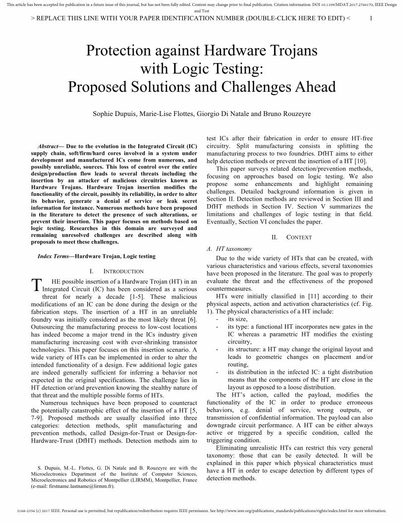
HTs were initially classified in [11] according to their physical aspects, action and activation characteristics (cf. Fig. 1). The physical characteristics of a HT include:
- its size, - its type: a functional HT incorporates new gates in the
IC whereas a parametric HT modifies the existing circuitry,
- its structure: a HT may change the original layout and leads to geometric changes on placement and/or routing,
- its distribution in the infected IC: a tight distribution means that the components of the HT are close in the layout as opposed to a loose distribution.
The HT’s action, called the payload, modifies the functionality of the IC in order to produce erroneous behaviors, e.g. denial of service, wrong outputs, or transmission of confidential information. The payload can also downgrade circuit performance. A HT can be either always active or triggered by a specific condition, called the triggering condition.
Eliminating unrealistic HTs can restrict this very general taxonomy: those that can be easily detected. It will be explained in this paper which physical characteristics must have a HT in order to escape detection by different types of detection methods.
Protection against Hardware Trojans with Logic Testing:
Proposed Solutions and Challenges Ahead Sophie Dupuis, Marie-Lise Flottes, Giorgio Di Natale and Bruno Rouzeyre
T
2168-2356 (c) 2017 IEEE. Personal use is permitted, but republication/redistribution requires IEEE permission. See http://www.ieee.org/publications_standards/publications/rights/index.html for more information.
This article has been accepted for publication in a future issue of this journal, but has not been fully edited. Content may change prior to final publication. Citation information: DOI 10.1109/MDAT.2017.2766170, IEEE Designand Test
> REPLACE THIS LINE WITH YOUR PAPER IDENTIFICATION NUMBER (DOUBLE-CLICK HERE TO EDIT) <
2
Besides, this taxonomy focuses on HTs possibly inserted in an unreliable foundry. All steps in the design are nowadays considered as unreliable. To take into account these new threats, new taxonomies were proposed to characterize HTs inserted at design time, in a third party Intellectual Property for instance. Abstraction level and insertion phase are taken into account in such taxonomies [12]. These HTs are beyond the scope of this paper.
Moreover, the knowledge of the circuit that an attacker must have, depending on the desired functionality of the HT, is presented in [12]. For example, the knowledge of the functionality and/or the netlist is not necessary to notch a few signals in order to cause an eventual failure. On the contrary, this knowledge is necessary to modify the functionality, e.g. to transmit a specific internal value at a given time.
B. Protection methods taxonomy Many techniques have been proposed to counteract the
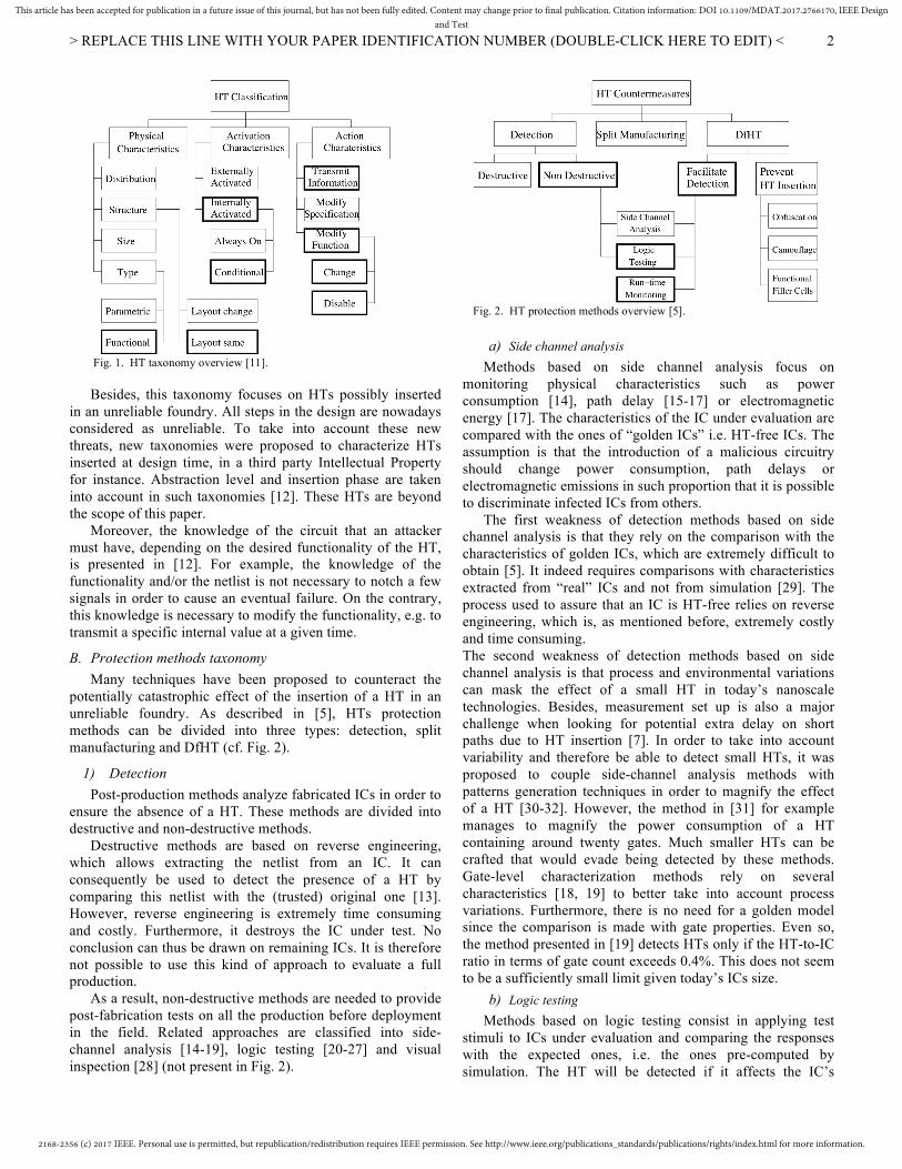
potentially catastrophic effect of the insertion of a HT in an unreliable foundry. As described in [5], HTs protection methods can be divided into three types: detection, split manufacturing and DfHT (cf. Fig. 2).
1) Detection Post-production methods analyze fabricated ICs in order to
ensure the absence of a HT. These methods are divided into destructive and non-destructive methods.
Destructive methods are based on reverse engineering, which allows extracting the netlist from an IC. It can consequently be used to detect the presence of a HT by comparing this netlist with the (trusted) original one [13]. However, reverse engineering is extremely time consuming and costly. Furthermore, it destroys the IC under test. No conclusion can thus be drawn on remaining ICs. It is therefore not possible to use this kind of approach to evaluate a full production.
As a result, non-destructive methods are needed to provide post-fabrication tests on all the production before deployment in the field. Related approaches are classified into side-channel analysis [14-19], logic testing [20-27] and visual inspection [28] (not present in Fig. 2).
a) Side channel analysis Methods based on side channel analysis focus on
monitoring physical characteristics such as power consumption [14], path delay [15-17] or electromagnetic energy [17]. The characteristics of the IC under evaluation are compared with the ones of “golden ICs” i.e. HT-free ICs. The assumption is that the introduction of a malicious circuitry should change power consumption, path delays or electromagnetic emissions in such proportion that it is possible to discriminate infected ICs from others.
The first weakness of detection methods based on side channel analysis is that they rely on the comparison with the characteristics of golden ICs, which are extremely difficult to obtain [5]. It indeed requires comparisons with characteristics extracted from “real” ICs and not from simulation [29]. The process used to assure that an IC is HT-free relies on reverse engineering, which is, as mentioned before, extremely costly and time consuming. The second weakness of detection methods based on side channel analysis is that process and environmental variations can mask the effect of a small HT in today’s nanoscale technologies. Besides, measurement set up is also a major challenge when looking for potential extra delay on short paths due to HT insertion [7]. In order to take into account variability and therefore be able to detect small HTs, it was proposed to couple side-channel analysis methods with patterns generation techniques in order to magnify the effect of a HT [30-32]. However, the method in [31] for example manages to magnify the power consumption of a HT containing around twenty gates. Much smaller HTs can be crafted that would evade being detected by these methods. Gate-level characterization methods rely on several characteristics [18, 19] to better take into account process variations. Furthermore, there is no need for a golden model since the comparison is made with gate properties. Even so, the method presented in [19] detects HTs only if the HT-to-IC ratio in terms of gate count exceeds 0.4%. This does not seem to be a sufficiently small limit given today’s ICs size.
b) Logic testing Methods based on logic testing consist in applying test
stimuli to ICs under evaluation and comparing the responses with the expected ones, i.e. the ones pre-computed by simulation. The HT will be detected if it affects the IC’s
Fig. 2. HT protection methods overview [5].
Fig. 1. HT taxonomy overview [11].
2168-2356 (c) 2017 IEEE. Personal use is permitted, but republication/redistribution requires IEEE permission. See http://www.ieee.org/publications_standards/publications/rights/index.html for more information.
This article has been accepted for publication in a future issue of this journal, but has not been fully edited. Content may change prior to final publication. Citation information: DOI 10.1109/MDAT.2017.2766170, IEEE Designand Test
> REPLACE THIS LINE WITH YOUR PAPER IDENTIFICATION NUMBER (DOUBLE-CLICK HERE TO EDIT) <
3
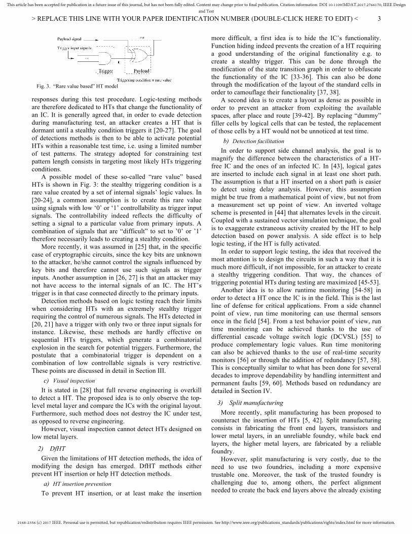
responses during this test procedure. Logic-testing methods are therefore dedicated to HTs that change the functionality of an IC. It is generally agreed that, in order to evade detection during manufacturing test, an attacker creates a HT that is dormant until a stealthy condition triggers it [20-27]. The goal of detections methods is then to be able to activate potential HTs within a reasonable test time, i.e. using a limited number of test patterns. The strategy adopted for constraining test pattern length consists in targeting most likely HTs triggering conditions.
A possible model of these so-called “rare value” based HTs is shown in Fig. 3: the stealthy triggering condition is a rare value created by a set of internal signals’ logic values. In [20-24], a common assumption is to create this rare value using signals with low ‘0’ or ‘1’ controllability as trigger input signals. The controllability indeed reflects the difficulty of setting a signal to a particular value from primary inputs. A combination of signals that are “difficult” to set to ’0’ or ’1’ therefore necessarily leads to creating a stealthy condition.
More recently, it was assumed in [25] that, in the specific case of cryptographic circuits, since the key bits are unknown to the attacker, he/she cannot control the signals influenced by key bits and therefore cannot use such signals as trigger inputs. Another assumption in [26, 27] is that an attacker may not have access to the internal signals of an IC. The HT’s trigger is in that case connected directly to the primary inputs.
Detection methods based on logic testing reach their limits when considering HTs with an extremely stealthy trigger requiring the control of numerous signals. The HTs detected in [20, 21] have a trigger with only two or three input signals for instance. Likewise, these methods are hardly effective on sequential HTs triggers, which generate a combinatorial explosion in the search for potential triggers. Furthermore, the postulate that a combinatorial trigger is dependent on a combination of low controllable signals is very restrictive. These points are discussed in detail in Section III.
c) Visual inspection It is stated in [28] that full reverse engineering is overkill
to detect a HT. The proposed idea is to only observe the top-level metal layer and compare the ICs with the original layout. Furthermore, such method does not destroy the IC under test, as opposed to reverse engineering.
However, visual inspection cannot detect HTs designed on low metal layers.
2) DfHT Given the limitations of HT detection methods, the idea of
modifying the design has emerged. DfHT methods either prevent HT insertion or help HT detection methods.
a) HT insertion prevention To prevent HT insertion, or at least make the insertion
more difficult, a first idea is to hide the IC’s functionality. Function hiding indeed prevents the creation of a HT requiring a good understanding of the original functionality e.g. to create a stealthy trigger. This can be done through the modification of the state transition graph in order to obfuscate the functionality of the IC [33-36]. This can also be done through the modification of the layout of the standard cells in order to camouflage their functionality [37, 38].
A second idea is to create a layout as dense as possible in order to prevent an attacker from exploiting the available spaces, after place and route [39-42]. By replacing “dummy” filler cells by logical cells that can be tested, the replacement of those cells by a HT would not be unnoticed at test time.
b) Detection facilitation In order to support side channel analysis, the goal is to
magnify the difference between the characteristics of a HT-free IC and the ones of an infected IC. In [43], logical gates are inserted to include each signal in at least one short path. The assumption is that a HT inserted on a short path is easier to detect using delay analysis. However, this assumption might be true from a mathematical point of view, but not from a measurement set up point of view. An inverted voltage scheme is presented in [44] that alternates levels in the circuit. Coupled with a sustained vector simulation technique, the goal is to exaggerate extraneous activity created by the HT to help detection based on power analysis. A side effect is to help logic testing, if the HT is fully activated.
In order to support logic testing, the idea that received the most attention is to design the circuits in such a way that it is much more difficult, if not impossible, for an attacker to create a stealthy triggering condition. That way, the chances of triggering potential HTs during testing are maximized [45-53].
Another idea is to allow runtime monitoring [54-58] in order to detect a HT once the IC is in the field. This is the last line of defense for critical applications. From a side channel point of view, run time monitoring can use thermal sensors once in the field [54]. From a test behavior point of view, run time monitoring can be achieved thanks to the use of differential cascade voltage switch logic (DCVSL) [55] to produce complementary logic values. Run time monitoring can also be achieved thanks to the use of real-time security monitors [56] or through the addition of redundancy [57, 58]. This is conceptually similar to what has been done for several decades to improve dependability by handling intermittent and permanent faults [59, 60]. Methods based on redundancy are detailed in Section IV.
3) Split manufacturing More recently, split manufacturing has been proposed to
counteract the insertion of HTs [5, 42]. Split manufacturing consists in fabricating the front end layers, transistors and lower metal layers, in an unreliable foundry, while back end layers, the higher metal layers, are fabricated by a reliable foundry.
However, split manufacturing is very costly, due to the need to use two foundries, including a more expensive trustable one. Moreover, the task of the trusted foundry is challenging due to, among others, the perfect alignment needed to create the back end layers above the already existing
Fig. 3. “Rare value based” HT model
2168-2356 (c) 2017 IEEE. Personal use is permitted, but republication/redistribution requires IEEE permission. See http://www.ieee.org/publications_standards/publications/rights/index.html for more information.
This article has been accepted for publication in a future issue of this journal, but has not been fully edited. Content may change prior to final publication. Citation information: DOI 10.1109/MDAT.2017.2766170, IEEE Designand Test
> REPLACE THIS LINE WITH YOUR PAPER IDENTIFICATION NUMBER (DOUBLE-CLICK HERE TO EDIT) <
4
front end layers. Besides, it has been shown that split manufacturing doesn’t provide the expected security [61]: an attacker in the unreliable foundry can indeed guess most of the missing connections. More research on split manufacturing is still therefore needed, not only on 2D integration, but also on 3D integration [5].
C. Threat model The remainder of this paper focuses on HTs possibly
introduced in an unreliable foundry. We assume that the attacker does his/her best to craft a HT that will not be detected by any existing method. The HT is therefore supposed to be small enough to escape detection by methods based on side channel analysis and visual inspection.
Besides, focus is made on methods based on logic testing (cf. bolded rectangles in Fig. 2). The HTs covered by this type of methods are supposed to be stealthy triggered HTs that modify the functionality of the IC. In other words, an erroneous output can be observed when the HT is triggered by a stealthy condition (cf. bolded rectangles in Fig. 1). So that the erroneous behavior is detected, a comparison is made with the expected answers, known thanks to the test sequence. It should be noted the “golden model” with which to compare is not a HT free IC as for methods based on side channel analysis. Only the expected behavior of the circuit is needed. Since, in our threat model, no HT is supposed to be inserted during the design, the golden model is the test sequence generated from the HT free netlist by the trusted designer.
Based on these assumptions, the goal of the detection methods is to generate a reduced set of test patterns dedicated to the activation, and thus detection through output observation, of potential HTs at test time. DfHT methods aim at facilitating detection by preventing the attacker from creating a stealthy condition, or/and allowing HT detection at run-time.
The following sections provide a review of solutions from the literature and discuss possible improvements.
III. DETECTION This Section reviews HT detection methods based on logic
testing after showing similarities and difference with stuck-at fault logic testing. Eventually, two limitations are put forward: the difficulty of managing sequential triggers and triggers based on controllable signals.
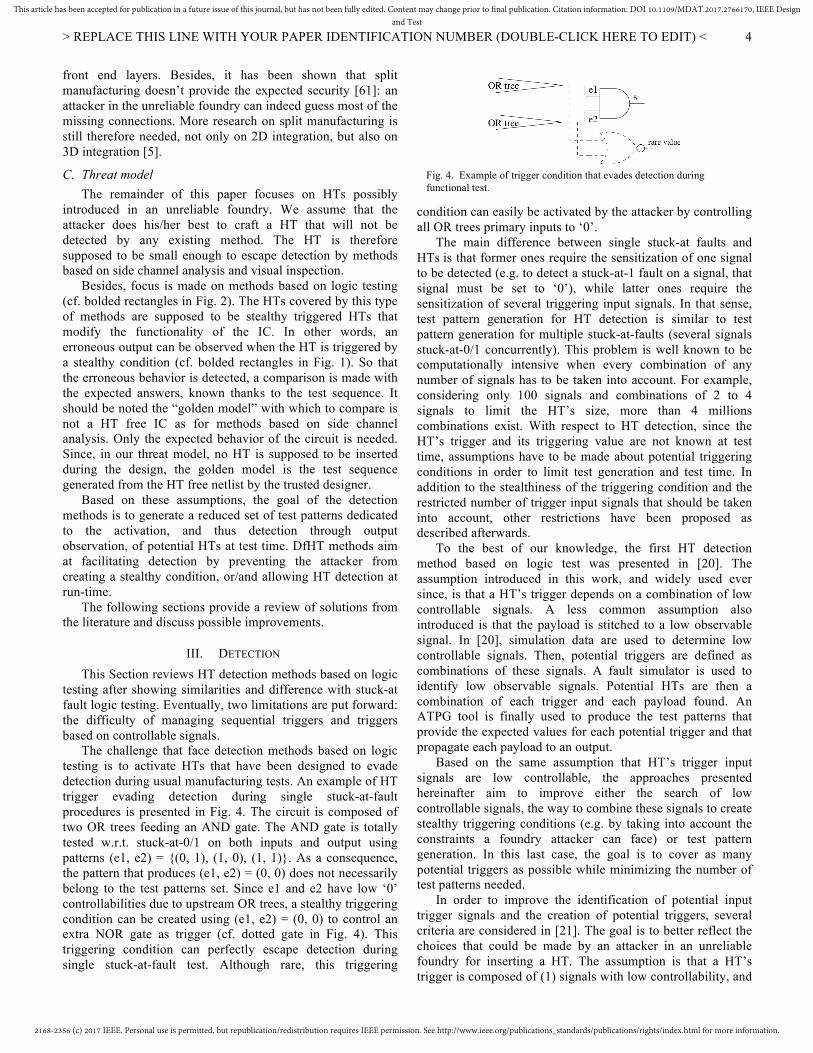
The challenge that face detection methods based on logic testing is to activate HTs that have been designed to evade detection during usual manufacturing tests. An example of HT trigger evading detection during single stuck-at-fault procedures is presented in Fig. 4. The circuit is composed of two OR trees feeding an AND gate. The AND gate is totally tested w.r.t. stuck-at-0/1 on both inputs and output using patterns (e1, e2) = {(0, 1), (1, 0), (1, 1)}. As a consequence, the pattern that produces (e1, e2) = (0, 0) does not necessarily belong to the test patterns set. Since e1 and e2 have low ‘0’ controllabilities due to upstream OR trees, a stealthy triggering condition can be created using (e1, e2) = (0, 0) to control an extra NOR gate as trigger (cf. dotted gate in Fig. 4). This triggering condition can perfectly escape detection during single stuck-at-fault test. Although rare, this triggering
condition can easily be activated by the attacker by controlling all OR trees primary inputs to ‘0’.
The main difference between single stuck-at faults and HTs is that former ones require the sensitization of one signal to be detected (e.g. to detect a stuck-at-1 fault on a signal, that signal must be set to ‘0’), while latter ones require the sensitization of several triggering input signals. In that sense, test pattern generation for HT detection is similar to test pattern generation for multiple stuck-at-faults (several signals stuck-at-0/1 concurrently). This problem is well known to be computationally intensive when every combination of any number of signals has to be taken into account. For example, considering only 100 signals and combinations of 2 to 4 signals to limit the HT’s size, more than 4 millions combinations exist. With respect to HT detection, since the HT’s trigger and its triggering value are not known at test time, assumptions have to be made about potential triggering conditions in order to limit test generation and test time. In addition to the stealthiness of the triggering condition and the restricted number of trigger input signals that should be taken into account, other restrictions have been proposed as described afterwards.
To the best of our knowledge, the first HT detection method based on logic test was presented in [20]. The assumption introduced in this work, and widely used ever since, is that a HT’s trigger depends on a combination of low controllable signals. A less common assumption also introduced is that the payload is stitched to a low observable signal. In [20], simulation data are used to determine low controllable signals. Then, potential triggers are defined as combinations of these signals. A fault simulator is used to identify low observable signals. Potential HTs are then a combination of each trigger and each payload found. An ATPG tool is finally used to produce the test patterns that provide the expected values for each potential trigger and that propagate each payload to an output.
Based on the same assumption that HT’s trigger input signals are low controllable, the approaches presented hereinafter aim to improve either the search of low controllable signals, the way to combine these signals to create stealthy triggering conditions (e.g. by taking into account the constraints a foundry attacker can face) or test pattern generation. In this last case, the goal is to cover as many potential triggers as possible while minimizing the number of test patterns needed.
In order to improve the identification of potential input trigger signals and the creation of potential triggers, several criteria are considered in [21]. The goal is to better reflect the choices that could be made by an attacker in an unreliable foundry for inserting a HT. The assumption is that a HT’s trigger is composed of (1) signals with low controllability, and
Fig. 4. Example of trigger condition that evades detection during functional test.
2168-2356 (c) 2017 IEEE. Personal use is permitted, but republication/redistribution requires IEEE permission. See http://www.ieee.org/publications_standards/publications/rights/index.html for more information.
This article has been accepted for publication in a future issue of this journal, but has not been fully edited. Content may change prior to final publication. Citation information: DOI 10.1109/MDAT.2017.2766170, IEEE Designand Test
> REPLACE THIS LINE WITH YOUR PAPER IDENTIFICATION NUMBER (DOUBLE-CLICK HERE TO EDIT) <
5
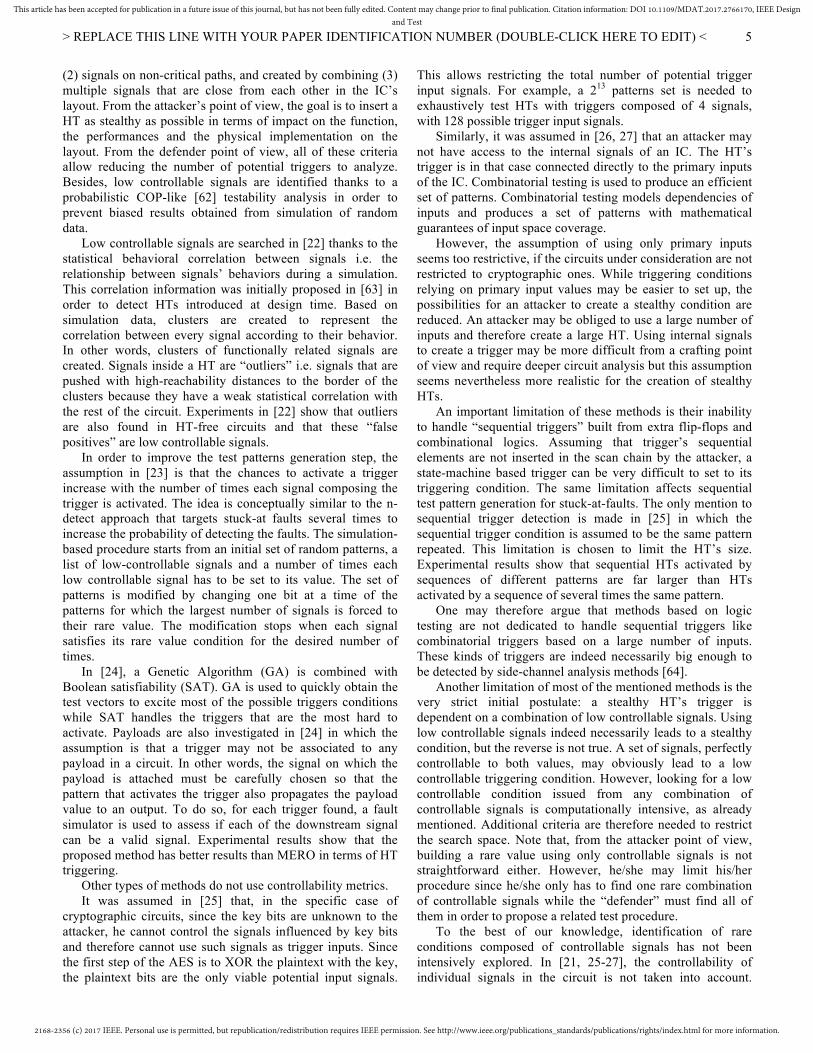
(2) signals on non-critical paths, and created by combining (3) multiple signals that are close from each other in the IC’s layout. From the attacker’s point of view, the goal is to insert a HT as stealthy as possible in terms of impact on the function, the performances and the physical implementation on the layout. From the defender point of view, all of these criteria allow reducing the number of potential triggers to analyze. Besides, low controllable signals are identified thanks to a probabilistic COP-like [62] testability analysis in order to prevent biased results obtained from simulation of random data.
Low controllable signals are searched in [22] thanks to the statistical behavioral correlation between signals i.e. the relationship between signals’ behaviors during a simulation. This correlation information was initially proposed in [63] in order to detect HTs introduced at design time. Based on simulation data, clusters are created to represent the correlation between every signal according to their behavior. In other words, clusters of functionally related signals are created. Signals inside a HT are “outliers” i.e. signals that are pushed with high-reachability distances to the border of the clusters because they have a weak statistical correlation with the rest of the circuit. Experiments in [22] show that outliers are also found in HT-free circuits and that these “false positives” are low controllable signals.
In order to improve the test patterns generation step, the assumption in [23] is that the chances to activate a trigger increase with the number of times each signal composing the trigger is activated. The idea is conceptually similar to the n-detect approach that targets stuck-at faults several times to increase the probability of detecting the faults. The simulation-based procedure starts from an initial set of random patterns, a list of low-controllable signals and a number of times each low controllable signal has to be set to its value. The set of patterns is modified by changing one bit at a time of the patterns for which the largest number of signals is forced to their rare value. The modification stops when each signal satisfies its rare value condition for the desired number of times.
In [24], a Genetic Algorithm (GA) is combined with Boolean satisfiability (SAT). GA is used to quickly obtain the test vectors to excite most of the possible triggers conditions while SAT handles the triggers that are the most hard to activate. Payloads are also investigated in [24] in which the assumption is that a trigger may not be associated to any payload in a circuit. In other words, the signal on which the payload is attached must be carefully chosen so that the pattern that activates the trigger also propagates the payload value to an output. To do so, for each trigger found, a fault simulator is used to assess if each of the downstream signal can be a valid signal. Experimental results show that the proposed method has better results than MERO in terms of HT triggering.
Other types of methods do not use controllability metrics. It was assumed in [25] that, in the specific case of
cryptographic circuits, since the key bits are unknown to the attacker, he cannot control the signals influenced by key bits and therefore cannot use such signals as trigger inputs. Since the first step of the AES is to XOR the plaintext with the key, the plaintext bits are the only viable potential input signals.
This allows restricting the total number of potential trigger input signals. For example, a 213 patterns set is needed to exhaustively test HTs with triggers composed of 4 signals, with 128 possible trigger input signals.
Similarly, it was assumed in [26, 27] that an attacker may not have access to the internal signals of an IC. The HT’s trigger is in that case connected directly to the primary inputs of the IC. Combinatorial testing is used to produce an efficient set of patterns. Combinatorial testing models dependencies of inputs and produces a set of patterns with mathematical guarantees of input space coverage.
However, the assumption of using only primary inputs seems too restrictive, if the circuits under consideration are not restricted to cryptographic ones. While triggering conditions relying on primary input values may be easier to set up, the possibilities for an attacker to create a stealthy condition are reduced. An attacker may be obliged to use a large number of inputs and therefore create a large HT. Using internal signals to create a trigger may be more difficult from a crafting point of view and require deeper circuit analysis but this assumption seems nevertheless more realistic for the creation of stealthy HTs.
An important limitation of these methods is their inability to handle “sequential triggers” built from extra flip-flops and combinational logics. Assuming that trigger’s sequential elements are not inserted in the scan chain by the attacker, a state-machine based trigger can be very difficult to set to its triggering condition. The same limitation affects sequential test pattern generation for stuck-at-faults. The only mention to sequential trigger detection is made in [25] in which the sequential trigger condition is assumed to be the same pattern repeated. This limitation is chosen to limit the HT’s size. Experimental results show that sequential HTs activated by sequences of different patterns are far larger than HTs activated by a sequence of several times the same pattern.
One may therefore argue that methods based on logic testing are not dedicated to handle sequential triggers like combinatorial triggers based on a large number of inputs. These kinds of triggers are indeed necessarily big enough to be detected by side-channel analysis methods [64].
Another limitation of most of the mentioned methods is the very strict initial postulate: a stealthy HT’s trigger is dependent on a combination of low controllable signals. Using low controllable signals indeed necessarily leads to a stealthy condition, but the reverse is not true. A set of signals, perfectly controllable to both values, may obviously lead to a low controllable triggering condition. However, looking for a low controllable condition issued from any combination of controllable signals is computationally intensive, as already mentioned. Additional criteria are therefore needed to restrict the search space. Note that, from the attacker point of view, building a rare value using only controllable signals is not straightforward either. However, he/she may limit his/her procedure since he/she only has to find one rare combination of controllable signals while the “defender” must find all of them in order to propose a related test procedure.
To the best of our knowledge, identification of rare conditions composed of controllable signals has not been intensively explored. In [21, 25-27], the controllability of individual signals in the circuit is not taken into account.
2168-2356 (c) 2017 IEEE. Personal use is permitted, but republication/redistribution requires IEEE permission. See http://www.ieee.org/publications_standards/publications/rights/index.html for more information.
This article has been accepted for publication in a future issue of this journal, but has not been fully edited. Content may change prior to final publication. Citation information: DOI 10.1109/MDAT.2017.2766170, IEEE Designand Test
> REPLACE THIS LINE WITH YOUR PAPER IDENTIFICATION NUMBER (DOUBLE-CLICK HERE TO EDIT) <
6
Exploration of potential triggering conditions is driven by a signal proximity criterion in [21], assuming that it is easier for an attacker to use nearby signals. Only primary inputs are considered in [26, 27] (also from a easiness point of view for the attacker) and in [25] (specific case of cryptographic circuits).
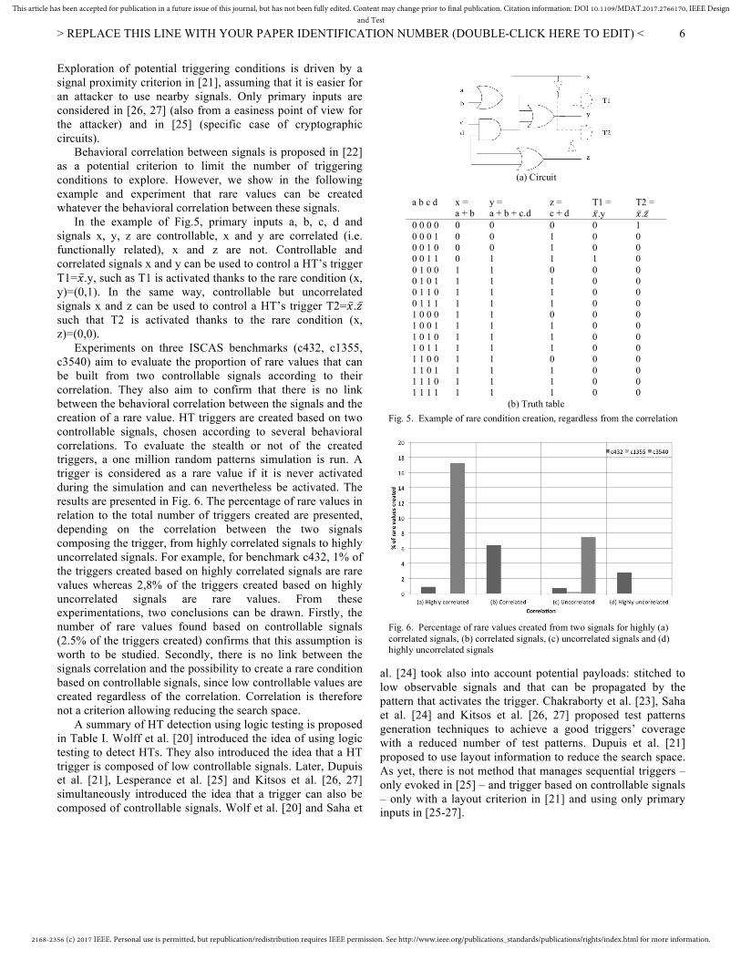
Behavioral correlation between signals is proposed in [22] as a potential criterion to limit the number of triggering conditions to explore. However, we show in the following example and experiment that rare values can be created whatever the behavioral correlation between these signals.
In the example of Fig.5, primary inputs a, b, c, d and signals x, y, z are controllable, x and y are correlated (i.e. functionally related), x and z are not. Controllable and correlated signals x and y can be used to control a HT’s trigger T1=𝑥.y, such as T1 is activated thanks to the rare condition (x, y)=(0,1). In the same way, controllable but uncorrelated signals x and z can be used to control a HT’s trigger T2=𝑥.𝑧 such that T2 is activated thanks to the rare condition (x, z)=(0,0).
Experiments on three ISCAS benchmarks (c432, c1355, c3540) aim to evaluate the proportion of rare values that can be built from two controllable signals according to their correlation. They also aim to confirm that there is no link between the behavioral correlation between the signals and the creation of a rare value. HT triggers are created based on two controllable signals, chosen according to several behavioral correlations. To evaluate the stealth or not of the created triggers, a one million random patterns simulation is run. A trigger is considered as a rare value if it is never activated during the simulation and can nevertheless be activated. The results are presented in Fig. 6. The percentage of rare values in relation to the total number of triggers created are presented, depending on the correlation between the two signals composing the trigger, from highly correlated signals to highly uncorrelated signals. For example, for benchmark c432, 1% of the triggers created based on highly correlated signals are rare values whereas 2,8% of the triggers created based on highly uncorrelated signals are rare values. From these experimentations, two conclusions can be drawn. Firstly, the number of rare values found based on controllable signals (2.5% of the triggers created) confirms that this assumption is worth to be studied. Secondly, there is no link between the signals correlation and the possibility to create a rare condition based on controllable signals, since low controllable values are created regardless of the correlation. Correlation is therefore not a criterion allowing reducing the search space.
A summary of HT detection using logic testing is proposed in Table I. Wolff et al. [20] introduced the idea of using logic testing to detect HTs. They also introduced the idea that a HT trigger is composed of low controllable signals. Later, Dupuis et al. [21], Lesperance et al. [25] and Kitsos et al. [26, 27] simultaneously introduced the idea that a trigger can also be composed of controllable signals. Wolf et al. [20] and Saha et
al. [24] took also into account potential payloads: stitched to low observable signals and that can be propagated by the pattern that activates the trigger. Chakraborty et al. [23], Saha et al. [24] and Kitsos et al. [26, 27] proposed test patterns generation techniques to achieve a good triggers’ coverage with a reduced number of test patterns. Dupuis et al. [21] proposed to use layout information to reduce the search space. As yet, there is not method that manages sequential triggers – only evoked in [25] – and trigger based on controllable signals – only with a layout criterion in [21] and using only primary inputs in [25-27].
(a) Circuit
a b c d x =
a + b y = a + b + c.d
z = c + d
T1 = �̅�.y
T2 = �̅�.𝑧 ̅
0 0 0 0 0 0 0 1 0 0 1 0 0 0 1 1 0 1 0 0 0 1 0 1 0 1 1 0 0 1 1 1 1 0 0 0 1 0 0 1 1 0 1 0 1 0 1 1 1 1 0 0 1 1 0 1 1 1 1 0 1 1 1 1
0 0 0 0 1 1 1 1 1 1 1 1 1 1 1 1
0 0 0 1 1 1 1 1 1 1 1 1 1 1 1 1
0 1 1 1 0 1 1 1 0 1 1 1 0 1 1 1
0 0 0 1 0 0 0 0 0 0 0 0 0 0 0 0
1 0 0 0 0 0 0 0 0 0 0 0 0 0 0 0
(b) Truth table Fig. 5. Example of rare condition creation, regardless from the correlation
Fig. 6. Percentage of rare values created from two signals for highly (a) correlated signals, (b) correlated signals, (c) uncorrelated signals and (d) highly uncorrelated signals
2168-2356 (c) 2017 IEEE. Personal use is permitted, but republication/redistribution requires IEEE permission. See http://www.ieee.org/publications_standards/publications/rights/index.html for more information.
This article has been accepted for publication in a future issue of this journal, but has not been fully edited. Content may change prior to final publication. Citation information: DOI 10.1109/MDAT.2017.2766170, IEEE Designand Test
> REPLACE THIS LINE WITH YOUR PAPER IDENTIFICATION NUMBER (DOUBLE-CLICK HERE TO EDIT) <
7
IV. DFHT
A. Logic testing This sub-section reviews prevention methods that aim to
enhance HT detection. In order to help detection with logic testing, all these methods share the common goal to facilitate the activation of potential HTs. Still assuming that stealthy triggers are controlled by low controllable signals, prevention techniques consist in increasing the controllability of low controllable signals such that HT triggering is more likely to happen during any test procedure (including random testing). Controllability improvement is easily achieved thanks to Design-for-Testability (DfT) methods commonly used for improving test pattern generation for stuck-at fault testing such as test point insertion [65] and partitioning [66]. Note that, unlike detection methods, these two types of methods are not specifically adapted to the problem of HT detection. These methods are intrinsically suited to the problem, and their use in this context is evaluated. Duality, initially dedicated to circuits’ reliability [59] is also explored as a way to help detection methods; so is logic masking, initially dedicated to counteract overproduction [67]. After reviewing proposed prevention methods, an improvement of test point insertion is proposed. Finally, one limitation is put forward: the difficulty of preventing triggers based on controllable signals.
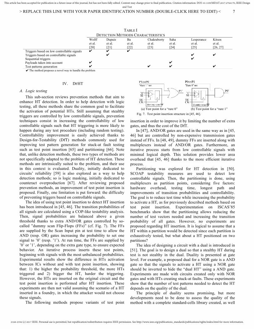
The idea of using test point insertion to detect HT insertion has been introduced in [45, 46]. The transition probabilities of all signals are calculated using a COP-like testability analysis. Then, signal probabilities are balanced above a given threshold thanks to extra AND/OR gates controlled by so-called ”dummy scan Flip-Flops (FFs)” (cf. Fig. 7). The FFs are supplied by the Scan Input pin at test time to allow the AND (resp. OR) gates increasing the probability to set one signal to ’0’ (resp. ’1’). At run time, the FFs are supplied by ’0’ or ’1’, depending on the extra gate type, to ensure expected behavior. An iterative process inserts these test points, beginning with signals with the most unbalanced probabilities. Experimental results show the difference in HTs activation between ICs without and with test point insertion, showing that: 1) the higher the probability threshold, the more HTs triggered and 2) bigger the HT, harder the triggering. However, the HTs are inserted on the original circuit and the test point insertion is performed after HT insertion. These experiments are then not valid assuming the scenario of a HT inserted in a foundry, in which the attacker would not choose these signals.
The following methods propose variants of test point
insertion in order to improve it by limiting the number of extra gates, and thus the cost of the DfT.
In [47], AND/OR gates are used in the same way as in [45, 46] but are controlled by non-expensive transmission gates instead of FFs. In [48, 49], dummy FFs are inserted along with multiplexers instead of AND/OR gates. Furthermore, an iterative process starts from low controllable signals with minimal logical depth. This solution provides lower area overhead that [45, 46] thanks to the more efficient iterative process.
Partitioning was explored for HT detection in [50]. SCOAP testability measures are used to detect low controllable signals. Then, the partitioning is done, using multiplexers as partition points, considering five factors: hardware overhead, testing time, longest path and improvements of transition probabilities and controllability. The goal is to reduce test time while increasing the probability to activate a HT, as for previously described methods based on test point insertion. Experimentation on ISCAS’85 benchmarks show that the partitioning allows reducing the number of test vectors needed and increasing the transition probability of all gates. However, no experiments are proposed regarding HT insertion. It is logical to assume that a HT within a partition would be detected since each partition is exhaustively tested, but what about a HT positioned on two partitions?
The idea of designing a circuit with a dual is introduced in [51]. The goal is to design a dual so that a stealthy HT during test is not stealthy in the dual. Duality is presented at gate level. For example, a proposed dual for a NOR gate is a AND gate so that the signals to activate a HT using a NOR gate should be inverted to hide the “dual HT” using a AND gate. Experiments are made with circuits created only with NOR gates and with HTs creating stuck-at faults. These experiments show that the number of test patterns needed to detect the HT depends on the quality of the dual.
The principle of duality seems promising, but more developments need to be done to assess the quality of the method with a complete standard-cells library created, as well
(a) Test point for a “rare 0” (b) Test point for a “rare 1”
Fig. 7. Test point insertion structure in [45, 46].
TABLE I DETECTION METHODS CHARACTERISTICS
Wolff et al. [20]
Dupuis et al. [21]
Ba et al. [22]
Chakraborty et al. [23]
Saha et al. [24]
Lesperance et al. [25]
Kitsos et al. [26, 27]
Triggers based on low controllable signals ✔ ✔ ✔ Triggers based on controllable signals ✔ ✔ ✔ Sequential triggers ✔ Payloads taken into account ✔ ✔ Test patterns generation ✔ ✔ ✔ ✔ ✔ The method proposes a novel way to handle the problem
2168-2356 (c) 2017 IEEE. Personal use is permitted, but republication/redistribution requires IEEE permission. See http://www.ieee.org/publications_standards/publications/rights/index.html for more information.
This article has been accepted for publication in a future issue of this journal, but has not been fully edited. Content may change prior to final publication. Citation information: DOI 10.1109/MDAT.2017.2766170, IEEE Designand Test
> REPLACE THIS LINE WITH YOUR PAPER IDENTIFICATION NUMBER (DOUBLE-CLICK HERE TO EDIT) <
8
as the overhead associated. Two variants of test point insertion are proposed in [52,
53], based on logic masking. Logic masking consists in inserting in the design extra logical gates and primary inputs to control them in order to change the behavior of the IC if the extra inputs are not controlled by an appropriate “secret key” [67].
In [52], a FSM is inserted controlled by a secret sequential key, that allows entering in a special operating mode upon the application of the right key (a specific sequence of inputs). In the special mode, called transparent mode, the least controllable signals are forced to their rare value and the least observable signals are compacted into a signature. As for some detection methods, potential payloads are taken into account. Due to the management of the transparent mode activation, and the management of both triggers and payloads, this method is more costly. However, it also provides the obfuscation of the initial design, as presented in the experimental results. Experiments regarding HT insertion are also proposed; however, the HT insertion is made randomly, which does not illustrate the behavior of an attacker.
AND/OR gates are inserted in [53], controlled by a combinational key, in order to remove low controllable signals. When the key bit is set to the non-dominant value, the signal can be controlled to its low controllable value, otherwise, the circuit behaves as defined by the specification.
These methods counteract both overproduction and HT insertion. Note that the protection against overproduction is thwarted if the attacker is able to retrieve the value of the key. However, the protection against HT insertion is not thwarted since, even if he/she knows which signals are not controllable in normal mode, this does not prevent these signals from being controlled during test by changing the value of the key. Protection against overproduction is beyond the scope of this paper, interested readers can refer to proposed methods [68-70], attacks [70, 71] and counterattacks [72-74].
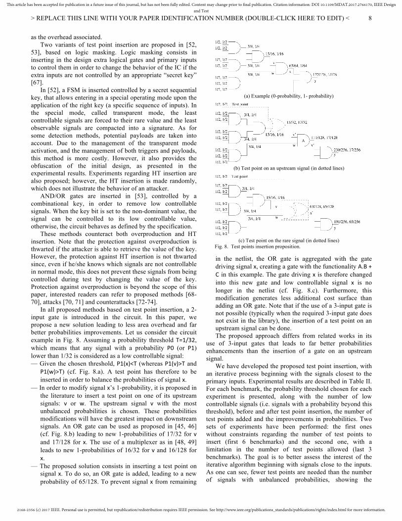
In all proposed methods based on test point insertion, a 2-input gate is introduced in the circuit. In this paper, we propose a new solution leading to less area overhead and far better probabilities improvements. Let us consider the circuit example in Fig. 8. Assuming a probability threshold T=1/32, which means that any signal with a probability P0 (or P1) lower than 1/32 is considered as a low controllable signal: — Given the chosen threshold, P1(x)<T (whereas P1(v)>T and
P1(w)>T) (cf. Fig. 8.a). A test point has therefore to be inserted in order to balance the probabilities of signal x.
— In order to modify signal x’s 1-probability, it is proposed in the literature to insert a test point on one of its upstream signals: v or w. The upstream signal v with the most unbalanced probabilities is chosen. These probabilities modifications will have the greatest impact on downstream signals. An OR gate can be used as proposed in [45, 46] (cf. Fig. 8.b) leading to new 1-probabilities of 17/32 for v and 17/128 for x. The use of a multiplexer as in [48, 49] leads to new 1-probabilities of 16/32 for v and 16/128 for x.
— The proposed solution consists in inserting a test point on signal x. To do so, an OR gate is added, leading to a new probability of 65/128. To prevent signal x from remaining
in the netlist, the OR gate is aggregated with the gate driving signal x, creating a gate with the functionality A.B+C in this example. The gate driving x is therefore changed into this new gate and low controllable signal x is no longer in the netlist (cf. Fig. 8.c). Furthermore, this modification generates less additional cost surface than adding an OR gate. Note that if the use of a 3-input gate is not possible (typically when the required 3-input gate does not exist in the library), the insertion of a test point on an upstream signal can be done. The proposed approach differs from related works in its
use of 3-input gates that leads to far better probabilities enhancements than the insertion of a gate on an upstream signal.
We have developed the proposed test point insertion, with an iterative process beginning with the signals closest to the primary inputs. Experimental results are described in Table II. For each benchmark, the probability threshold chosen for each experiment is presented, along with the number of low controllable signals (i.e. signals with a probability beyond this threshold), before and after test point insertion, the number of test points added and the improvements in probabilities. Two sets of experiments have been performed: the first ones without constraints regarding the number of test points to insert (first 6 benchmarks) and the second one, with a limitation in the number of test points allowed (last 3 benchmarks). The goal is to better assess the interest of the iterative algorithm beginning with signals close to the inputs. As one can see, fewer test points are needed than the number of signals with unbalanced probabilities, showing the
(a) Example (0-probability, 1- probability)
(b) Test point on an upstream signal (in dotted lines)
(c) Test point on the rare signal (in dotted lines)
Fig. 8. Test points insertion proposition.
2168-2356 (c) 2017 IEEE. Personal use is permitted, but republication/redistribution requires IEEE permission. See http://www.ieee.org/publications_standards/publications/rights/index.html for more information.
This article has been accepted for publication in a future issue of this journal, but has not been fully edited. Content may change prior to final publication. Citation information: DOI 10.1109/MDAT.2017.2766170, IEEE Designand Test
> REPLACE THIS LINE WITH YOUR PAPER IDENTIFICATION NUMBER (DOUBLE-CLICK HERE TO EDIT) <
9
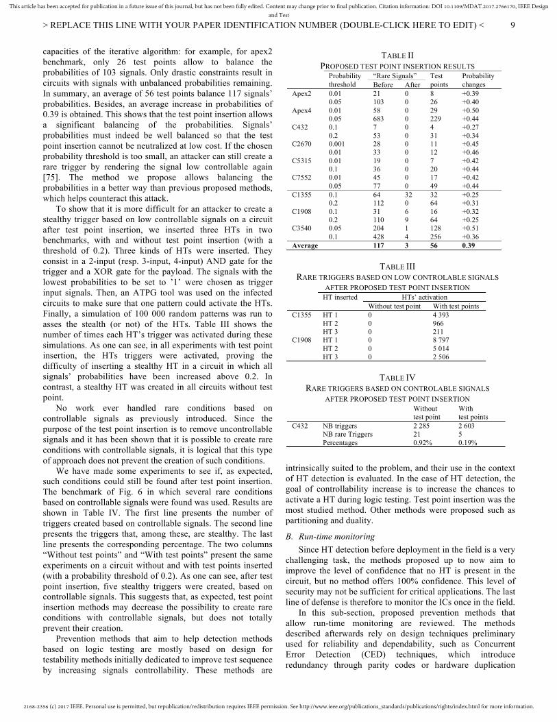
capacities of the iterative algorithm: for example, for apex2 benchmark, only 26 test points allow to balance the probabilities of 103 signals. Only drastic constraints result in circuits with signals with unbalanced probabilities remaining. In summary, an average of 56 test points balance 117 signals’ probabilities. Besides, an average increase in probabilities of 0.39 is obtained. This shows that the test point insertion allows a significant balancing of the probabilities. Signals’ probabilities must indeed be well balanced so that the test point insertion cannot be neutralized at low cost. If the chosen probability threshold is too small, an attacker can still create a rare trigger by rendering the signal low controllable again [75]. The method we propose allows balancing the probabilities in a better way than previous proposed methods, which helps counteract this attack.
To show that it is more difficult for an attacker to create a stealthy trigger based on low controllable signals on a circuit after test point insertion, we inserted three HTs in two benchmarks, with and without test point insertion (with a threshold of 0.2). Three kinds of HTs were inserted. They consist in a 2-input (resp. 3-input, 4-input) AND gate for the trigger and a XOR gate for the payload. The signals with the lowest probabilities to be set to ’1’ were chosen as trigger input signals. Then, an ATPG tool was used on the infected circuits to make sure that one pattern could activate the HTs. Finally, a simulation of 100 000 random patterns was run to asses the stealth (or not) of the HTs. Table III shows the number of times each HT’s trigger was activated during these simulations. As one can see, in all experiments with test point insertion, the HTs triggers were activated, proving the difficulty of inserting a stealthy HT in a circuit in which all signals’ probabilities have been increased above 0.2. In contrast, a stealthy HT was created in all circuits without test point.
No work ever handled rare conditions based on controllable signals as previously introduced. Since the purpose of the test point insertion is to remove uncontrollable signals and it has been shown that it is possible to create rare conditions with controllable signals, it is logical that this type of approach does not prevent the creation of such conditions.
We have made some experiments to see if, as expected, such conditions could still be found after test point insertion. The benchmark of Fig. 6 in which several rare conditions based on controllable signals were found was used. Results are shown in Table IV. The first line presents the number of triggers created based on controllable signals. The second line presents the triggers that, among these, are stealthy. The last line presents the corresponding percentage. The two columns “Without test points” and “With test points” present the same experiments on a circuit without and with test points inserted (with a probability threshold of 0.2). As one can see, after test point insertion, five stealthy triggers were created, based on controllable signals. This suggests that, as expected, test point insertion methods may decrease the possibility to create rare conditions with controllable signals, but does not totally prevent their creation.
Prevention methods that aim to help detection methods based on logic testing are mostly based on design for testability methods initially dedicated to improve test sequence by increasing signals controllability. These methods are
intrinsically suited to the problem, and their use in the context of HT detection is evaluated. In the case of HT detection, the goal of controllability increase is to increase the chances to activate a HT during logic testing. Test point insertion was the most studied method. Other methods were proposed such as partitioning and duality.
B. Run-time monitoring Since HT detection before deployment in the field is a very
challenging task, the methods proposed up to now aim to improve the level of confidence that no HT is present in the circuit, but no method offers 100% confidence. This level of security may not be sufficient for critical applications. The last line of defense is therefore to monitor the ICs once in the field.
In this sub-section, proposed prevention methods that allow run-time monitoring are reviewed. The methods described afterwards rely on design techniques preliminary used for reliability and dependability, such as Concurrent Error Detection (CED) techniques, which introduce redundancy through parity codes or hardware duplication
TABLE II PROPOSED TEST POINT INSERTION RESULTS
Probability threshold
“Rare Signals” Test points
Probability changes Before After
Apex2 Apex4 C432 C2670 C5315 C7552
0.01 0.05 0.01 0.05 0.1 0.2 0.001 0.01 0.01 0.1 0.01 0.05
21 103 58 683 7 53 28 33 19 36 45 77
0 0 0 0 0 0 0 0 0 0 0 0
8 26 29 229 4 31 11 12 7 20 17 49
+0.39 +0.40 +0.50 +0.44 +0.27 +0.34 +0.45 +0.46 +0.42 +0.44 +0.42 +0.44
C1355 C1908 C3540
0.1 0.2 0.1 0.2 0.05 0.1
64 112 31 110 204 428
32 0 6 9 1 4
32 64 16 64 128 256
+0.25 +0.31 +0.32 +0.25 +0.51 +0.36
Average 117 3 56 0.39
TABLE III RARE TRIGGERS BASED ON LOW CONTROLABLE SIGNALS
AFTER PROPOSED TEST POINT INSERTION HT inserted HTs’ activation Without test point With test points C1355 C1908
HT 1 HT 2 HT 3 HT 1 HT 2 HT 3
0 0 0 0 0 0
4 393 966 211 8 797 5 014 2 506
TABLE IV RARE TRIGGERS BASED ON CONTROLABLE SIGNALS
AFTER PROPOSED TEST POINT INSERTION Without
test point With test points
C432 NB triggers NB rare Triggers Percentages
2 285 21 0.92%
2 603 5 0.19%
2168-2356 (c) 2017 IEEE. Personal use is permitted, but republication/redistribution requires IEEE permission. See http://www.ieee.org/publications_standards/publications/rights/index.html for more information.
This article has been accepted for publication in a future issue of this journal, but has not been fully edited. Content may change prior to final publication. Citation information: DOI 10.1109/MDAT.2017.2766170, IEEE Designand Test
> REPLACE THIS LINE WITH YOUR PAPER IDENTIFICATION NUMBER (DOUBLE-CLICK HERE TO EDIT) <
10
along with a checker [76]. Then, the limitation of duplication is put forward: the difficulty of creating two "different" replicates of the same circuit in order to prevent an attacker from creating an identical HT in both replicates.
In [57], the proposed CED technique consists in a duplication-based on one-to-many code in order to protect the most “valuable” words that may appear on the ICs’ outputs. To do so, the IC is composed of two sub-circuits producing each a subgroup of the outputs (with the corresponding redundancy bits). A checker is then used to check the codewords. However, in order to limit the cost of the implementation, one has to choose the set of protected words (e.g. the most valuable or probable that appear on the outputs). Furthermore, the HT has to be activated for a certain period of time in order to be detected. The proposed method does not deal with HTs activated for a single cycle.
Hardware duplication is proposed [58]. The idea is to create a redundant and functionally equivalent circuit to the original one along with a comparator. If a HT is inserted in one of the two replicates, the comparator reports the abnormal behavior once the HT is activated and both replicates do not provide the same value. For this technique not to be countered by the attacker, he/she must not be able to create an identical HT in both replicates or tamper the comparator. The authors give leads to follow in order to create different replicates: different synthesis tools, different restrictions on the standard cell library, different design constraints, different state encoding (for finite-state-machines). Then, experimental data results are given to assess the difference between two replicates in terms of number of cells and area.
The idea introduced in [58] of using redundancy in order to hinder HT insertion is appealing. However, the experiments proposed to affirm that it is impossible for an attacker to create the same stealthy trigger in both replicates are not sufficient.
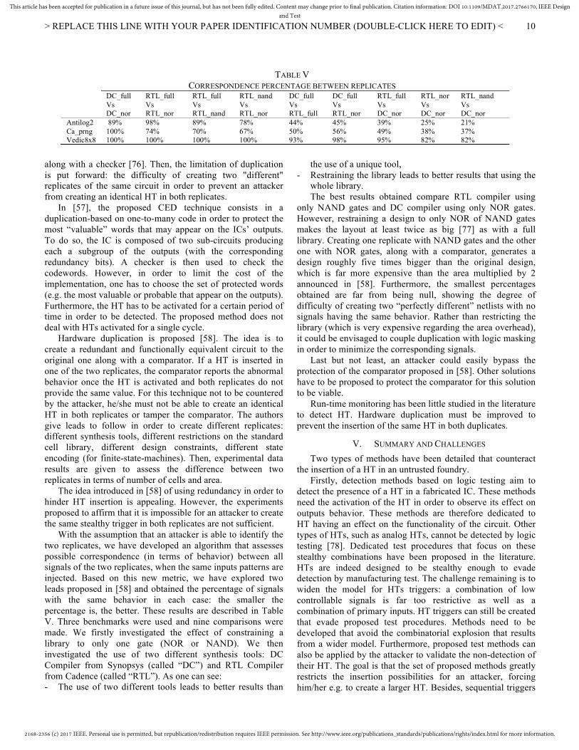
With the assumption that an attacker is able to identify the two replicates, we have developed an algorithm that assesses possible correspondence (in terms of behavior) between all signals of the two replicates, when the same inputs patterns are injected. Based on this new metric, we have explored two leads proposed in [58] and obtained the percentage of signals with the same behavior in each case: the smaller the percentage is, the better. These results are described in Table V. Three benchmarks were used and nine comparisons were made. We firstly investigated the effect of constraining a library to only one gate (NOR or NAND). We then investigated the use of two different synthesis tools: DC Compiler from Synopsys (called “DC”) and RTL Compiler from Cadence (called “RTL”). As one can see: - The use of two different tools leads to better results than
the use of a unique tool, - Restraining the library leads to better results that using the
whole library. The best results obtained compare RTL compiler using
only NAND gates and DC compiler using only NOR gates. However, restraining a design to only NOR of NAND gates makes the layout at least twice as big [77] as with a full library. Creating one replicate with NAND gates and the other one with NOR gates, along with a comparator, generates a design roughly five times bigger than the original design, which is far more expensive than the area multiplied by 2 announced in [58]. Furthermore, the smallest percentages obtained are far from being null, showing the degree of difficulty of creating two “perfectly different” netlists with no signals having the same behavior. Rather than restricting the library (which is very expensive regarding the area overhead), it could be envisaged to couple duplication with logic masking in order to minimize the corresponding signals.
Last but not least, an attacker could easily bypass the protection of the comparator proposed in [58]. Other solutions have to be proposed to protect the comparator for this solution to be viable.
Run-time monitoring has been little studied in the literature to detect HT. Hardware duplication must be improved to prevent the insertion of the same HT in both duplicates.
V. SUMMARY AND CHALLENGES Two types of methods have been detailed that counteract
the insertion of a HT in an untrusted foundry. Firstly, detection methods based on logic testing aim to
detect the presence of a HT in a fabricated IC. These methods need the activation of the HT in order to observe its effect on outputs behavior. These methods are therefore dedicated to HT having an effect on the functionality of the circuit. Other types of HTs, such as analog HTs, cannot be detected by logic testing [78]. Dedicated test procedures that focus on these stealthy combinations have been proposed in the literature. HTs are indeed designed to be stealthy enough to evade detection by manufacturing test. The challenge remaining is to widen the model for HTs triggers: a combination of low controllable signals is far too restrictive as well as a combination of primary inputs. HT triggers can still be created that evade proposed test procedures. Methods need to be developed that avoid the combinatorial explosion that results from a wider model. Furthermore, proposed test methods can also be applied by the attacker to validate the non-detection of their HT. The goal is that the set of proposed methods greatly restricts the insertion possibilities for an attacker, forcing him/her e.g. to create a larger HT. Besides, sequential triggers
TABLE V CORRESPONDENCE PERCENTAGE BETWEEN REPLICATES
DC_full Vs DC_nor
RTL_full Vs RTL_nor
RTL_full Vs RTL_nand
RTL_nand Vs RTL_nor
DC_full Vs RTL_full
DC_full Vs RTL_nor
RTL_full Vs DC_nor
RTL_nor Vs DC_nor
RTL_nand Vs DC_nor
Antilog2 89% 98% 89% 78% 44% 45% 39% 25% 21% Ca_prng 100% 74% 70% 67% 50% 56% 49% 38% 37% Vedic8x8 100% 100% 100% 100% 93% 98% 95% 82% 82%
2168-2356 (c) 2017 IEEE. Personal use is permitted, but republication/redistribution requires IEEE permission. See http://www.ieee.org/publications_standards/publications/rights/index.html for more information.
This article has been accepted for publication in a future issue of this journal, but has not been fully edited. Content may change prior to final publication. Citation information: DOI 10.1109/MDAT.2017.2766170, IEEE Designand Test
> REPLACE THIS LINE WITH YOUR PAPER IDENTIFICATION NUMBER (DOUBLE-CLICK HERE TO EDIT) <
11
are even more difficult to find. They are commonly supposed to be large enough to be found by methods based on side-channel analysis, however, the perfect complementarity of the two types of methods has never been shown.
Secondly Design-for-Hardware-Trust methods enhance the design flow to prevent the insertion of a HT, help detection methods or allow run-time monitoring. In order to help detection based on logic testing, the goal is to remove low controllable signals in a circuit to prevent the creation of a stealthy condition based on low controllable signals. The limitations lie in the same initial postulate regarding the way to create HTs triggers. In order to allow run-time monitoring, CED techniques have been proposed. They generate a large increase in area and do not provide a satisfactory solution for totally preventing the insertion of a HT.
One should notice that a HT must also escape detection by methods based on side-channel analysis. The HT must therefore be small enough to hidden within manufacturing variability. Logic testing and side-channel analysis are commonly described as complementary. However, to the best of our knowledge, no study has shown that the limits of one method fit perfectly within the abilities of the other.
VI. CONCLUSION Being able to detect a HT introduced in an unreliable
foundry during manufacturing test is a very challenging problem. For the past ten years, detection methods based on logic testing have been proposed. These methods allow assuring with a good degree of confidence that no HT has been inserted. Other detection methods, such as side-channel analysis, are also useful to detect other types of HTs. Furthermore, DfHT methods have been proposed to harden the insertion of a HT or to enhance detection methods capabilities. Besides, if detection at test time is not sufficient (e.g. for critical applications), detection at run-time has also been proposed in order to continuously monitor the ICs once in the field.
Given the diversity of possible types of HTs, one unique method cannot be effective for all HTs. Each method focuses on a particular type of HT. Ensuring 100% detectability seems impossible. Methods have to be combined to state with a great degree of confidence that no HT has been inserted. The task of an attacker is indeed rendered a lot more difficult, with great limits to what he can do due to various protections incorporated into the ICs: the HT has to be as small as possible to evade being detected by side channel analysis or visual inspection, and as stealthy as possible to evade being detected by logic testing.
In this paper, we have reviewed several methods proposed in the literature over the last decade, focusing on methods based on logic testing. The goal in that case is to generate reduced sets of test patterns that are likely to activate potential HTs activated by a stealthy condition. Most proposals are inspired by Design-for-Testability methods or methods that enhance reliability. They have been adapted for dealing with HTs. We have proposed enhancements for some methods and have also pointed the challenges that have not been resolved yet.
Besides, HTs inserted in unreliable foundries were the first
threat to be studied extensively; it was more recently considered that the threat might as well come from the design phase where a HT can be introduced by a rogue designer or through an IP from third party providers [5, 79-82].
ACKNOWLEDGMENTS The authors would like to thank Dr. Papa-Sidy Ba and M. Bastien Deveautour for their valuable work regarding the proposed experimentations.
REFERENCES [1] M. Tehranipoor and F. Koushanfar, “A survey of hardware trojan
taxonomy and detection”, In IEEE Design & Test of Computer, 27:10– 25, 2010.
[2] U. Guin, K. Huang, D. DiMase, J. M. Carulli, M. Tehranipoor and Y. Makris, “Counterfeit integrated circuits: a rising threat in the global semicondictor supply chain”, In Proceedings of the IEEE, Special Issue on Trustworthy Hardware, 102(8):1207–1228, 2014.
[3] S. Bhunia, M. S. Hsiao, M. Banga, S. Narasimhan, “Hardware Trojan Attacks: Threat Analysis and Countermeasures”, In Proceedings of the IEEE, Special Issue on Trustworthy Hardware, 102(8):1229–1247, 2014.
[4] H. Li, Q. Liu and J. Zhang, “A Survey of hardware Trojan threat and defense”, In Integration, the VLSI journal (2016), http://dx.doi.org/10.1016/j.vlsi.2016.01.004
[5] K. Xiao, D. Forte, Y. Jin, R. Karri, S. Bhunia and M. Tehranipoor, “Hardware Trojans: Lessons Learned after One Decade of Research”, In ACM Transactions od Design Automation of Electronic Systems, 22(1):1–23, 2016.
[6] R. S. Chakraborty, S. Narasimhan and S. Bhunia, “Hardware Trojan: Threats and Emerging Solutions”, In IEEE International High Level Design Validation and Test Workshop (HLDVT’09), pp. 166–171, 2009.
[7] M Tehranipoor, H. Salmani, X. Zhang, X. Wang, R. Karri, J. Rajendran and K. Rosenfeld, “Trustworthy Hardware: Trojan Detection and Design-for-Trust Challenges”, In IEEE Computer, pp. 66–74, 2011.
[8] S. Moein, J. Subramnian, T.A. Gulliver, F. Gebali and M.W. El-Kharashi, “Classification of Hardware Trojan Detection Techniques”, In International Conference on Computer Engineering and Systems, pp. 357–362, 2015.
[9] J. Francq and F. Frick, “Introduction to Hardware Trojan Detection Methods”, In Design Automation & Test in Europe (DATE’15), pp. 770–775, 2015.
[10] J. Rajendran, O. Sinanoglu and R. Karri, “Regaining Trust in VLSI Design: Design-for-Trust Techniques“, In Proceedings of the IEEE, Special Issue on Trustworthy Hardware, 102(8):1266–1282, 2014.
[11] X. Wang, M. Tehranipoor and J. Plusquellic, “Detecting Malicious Inclusion in Secure Hardware: Challenges and Solutions”, In IEEE International Workshop on Hardware-Oriented Security and Trust (HOST’08), pp. 15–19, 2008.
[12] R. Karri, J. Rajendran, K. Rosenfeld and M. Tehranipoor, “Trustworthy Hardware: Identifying and Classifying Hardware Trojans”, In IEEE Computer, pp. 39–46, 2010.
[13] C. Bao, D. Forte and A. Srivastava, “On Reverse Engineering-Based Hardware Trojan Detection”, In IEEE Transactions on Computer-Aided Design of Integrated Circuits and Sytems, 35(1):49–57, 2016.
[14] D.Agrawal, S.Baktir, D.Karakoyunlu, P.Rohatgi, and B.Sunar, “Trojan detection using IC fingerprinting“, In IEEE Symposium on Security and Privacy (SP’07), pp. 296–310, 2007.
[15] Y. Jin and Y. Makris, “Hardware Trojan Detection Using Path Delay Fingerprint“, In IEEE International Workshop on Hardware-Oriented Security and Trust (HOST’08), pp. 51–57, 2008.
[16] I. Exurville, L. Zussa, J.B. Rigaud and B. Robisson, “Resilient Hardware Trojans Detection based on Path Delay Measurement”, In International symposium on Hardware-Oriented Security and Trust (HOST’15), pp. 151–156, 2015.
[17] X.T. Ngo, I. Exurville, S. Bhasin, J.L. Danger, S. Guilley, Z. Najm, J.B. Rigaud and B. Robisson, “Hardware Trojan Detection by Delay and Electromagnetic Measurements”, In Design Automation & Test in
2168-2356 (c) 2017 IEEE. Personal use is permitted, but republication/redistribution requires IEEE permission. See http://www.ieee.org/publications_standards/publications/rights/index.html for more information.
This article has been accepted for publication in a future issue of this journal, but has not been fully edited. Content may change prior to final publication. Citation information: DOI 10.1109/MDAT.2017.2766170, IEEE Designand Test
> REPLACE THIS LINE WITH YOUR PAPER IDENTIFICATION NUMBER (DOUBLE-CLICK HERE TO EDIT) <
12
Europe (DATE’15), pp. 782–787, 2015. [18] M. Potkonjak, A. Nahapetian, M. Nelson and T. Massey, “Hardware
Trojan Horse Detection Using Gate-Level Characterisation”, In ACM/IEEE Design Automation Conference (DAC’09), pp. 688–693, 2009.
[19] L. Zhang and C.-H. Chang, “Hardware Trojan Detection with Linear Regression Based Gate-Level Characterisation”, In IEEE Asia Pacific Conference on Circuit sand Systems (APCCAS’14), pp. 256–259, 2014.
[20] F. Wolf, C. Papachristou, S. Bhunia and R. S. Chakraborty, “Towards Trojan-Free Trusted ICs: Problem Analysis and Detection Scheme“, In Design, Automation and Test in Europe (DATE’08), pp. 1362–1365, 2008.
[21] S. Dupuis, P.-S. Ba, M.-L. Flottes, G. Di Natale and B. Rouzeyre, “New Testing Procedure for Finding Insertion Sites of Stealthy Hardware Trojans”, In Design Automation & Test in Europe (DATE’15), pp. 776–781, 2015.
[22] P.-S. Ba, S. Dupuis, a, M.-L. Flottes, G. Di Natale and B. Rouzeyre, “Using Outliers to Detect Stealthy Hardware Trojan Triggering?”, In IEEE International Vefirication and Security Workshop (IVSW’16), pp. 39–44, 2016.
[23] R.S. Chakraborty, F. Wolff, S. Paul, C. Papachristou, and S. Bhunia, “MERO: a Statistical Approach for Hardware Trojan Detection“, In International Conference on Cryptographic Hardware and Embedded Systems (CHES’09), pp. 396–410, 2009.
[24] S. Saha, R.S. Chakraborty, S. Shashank, N. Anshul and D. Mukhopadhyay, “Improved Test Pattern Generation for Hardware Trojan Detection Using Genetic Algorithm and Boolean Satisfability”, In Cryptographic Hardware and Embedded Systems (CHES’15), pp. 577–596, 2015.
[25] N. Lesperance, S. Kulkarni and K.T. Cheng, “Hardware Trojan Detection Using Exhaustive Testing of k-bit Subspaces”, In Asia and South Pacific Design Automation Conference (ASP-DAC’15), 2015.
[26] P. Kitsos, D.E. Simos, J. Torres-Jimenez and A.G. Voyiatzis, “Exciting FPGA Cryptographic Trojans using Combinatorial Testing”, In IEEE International Symposium on Software Reliability Engineering (ISSRE’15), 2015.
[27] A.G. Voyiatzis, K.G. Stefanidis and P. Kitsos, “Efficient Triggering of Trojan Hardware Logic”, In International Symposium on Design and Diagnostics of Electronic Circuits and Systems (DDECS’16), pp. 200–205, 2016.
[28] S. Bhasin, J.L. Danger, X.T. Ngo and S. Guilley, “Hardware trojans horses in cryptographic IP cores”, In Fault Diagnostic and Tolerance in Cryptography (FDTC’13), pp. 15–29, 2013.
[29] S. Dupuis, G. Di Natale, M.-L. Flottes and B. Rouzeyre, “On the Effectiveness of Hardware Trojan Horse Detection via Side-Channel Analysis”, In Information Security Journal: A Global Perspective, 22(5–6):226–236, 2013.
[30] M. Banga, M. Chandrasekar, L. Fang and M.S. Hsiao, “Guided Test Generation for Isolation and Detection of Embedded Trojans in ICs”, In ACM Great Lakes Symposium on VLSI (GLSVLSI’08), pp. 363–366, 2008.
[31] M. Banga and M.S Hsiao, “A Novel Sustained Vector Technique for the Detection of Hardware Trojans”, In International Conference on VLSI Design (VLSI’09), pp. 327–332, 2009.
[32] X. Mingfu, H. Aiqun, H. Yi and L. Guyue, “Monte Carlo based Test Pattern Generation for Harware Trojan Detection”, In IEEE International Conference on Dependable, Automotic and Secure Computing (DASC’13), pp. 131–136, 2013.
[33] R.S Chakraborty and S. Bhunia, “HARPOON: An Obfuscation-Based SoC Design Methodology for Hardware Protection”, In IEEE Transactions on Computer-Aided Design of Integrated Circuits and Systems, 29(10):1493–1502, 2009.
[34] R.S. Chakraborty and S. Bhunia, “Security Against Hardware Trojan Attacks Using Key-Based Design Obfuscation”, In Journal of Electronic Testing, 27(6):767–785, 2011.
[35] X.T. Ngo, S. Bhasin, J.L. Danger, S. Guilley and Z. Najm, “Linear Complementary Dual Code Improvement to Strenghten Encoded Circuits against Hardware Trojan horses”, In IEEE International Workshop on Hardware-Oriented Security and Trust (HOST’15), pp. 82–87, 2015.
[36] J. Dofe, Y. Zhang and Q. Yu, “DSD: A Dynamic State-Deflection
Method for Gate-Level Netlist Obfuscation”, In IEEE Computer Society Annual Symposium on VLSI (ISVLSI’16), pp. 565–570, 2016.
[37] J. Rajendran, M. Sam, O. Sinagolu and R. Karri, “Security Analysis of Integrated Circuit Camouflaging”, In ACM SIGSAC Conference on Computer & Communications Security (CCS’13), pp. 709–720, 2013.
[38] M.I.R. Collantes, M.E. Massad and S. Garg, “Threshold Dependent Camouflaged Cells to Secure Circuits against Reverse Engineering Attacks”, In IEEE Computer Society annual Symposium on VLSI (ISLVI’16), pp. 443–448, 2016.
[39] K. Xiao and M. Tehranipoor, “BISA: Built-in Self-Authentication for Preventing Hardware Trojan Insertion”, In International Symposium on Hardware-Oriented Security and Trust (HOST’13), pp. 45–50, 2013.
[40] K. Xiao, D. Forte and M. Tehranipoor, “A Novel Built-In Self-Authentication Technique to Prevent Inserting Hardware Trojans”, In IEEE Transactions on Computer-aided Design of Integraded Circuits, 33(12):1778–1791, 2014.
[41] P.S. Ba, S. Dupuis, P. Manikandan, M.L. Flottes, G. Di Natale and B. Rouzeyre, “Hardware Trust through Layout Filling: a Hardware Trojan Prevention Technique”, In IEEE Computer Society annual Symposium on VLSI (ISLVI’16), pp. 254–259, 2016.
[42] K. Xiao, D. Forte and M. Tehranipoor, “Efficient and Secure Split Manufacturing via Obfuscated Built-In Self-Authentication”, In IEEE International Symposium on Hardware-Oriented Security and Trust (HOST’15), pp. 14–19, 2015.
[43] A. Nejat, D. Hely and V. Beroulle, “Facilitating Side Channel Analysis by Obfuscation for Hardware Trojan Detection”, In International Design & Test Symposium (IDT’15), pp. 129–134, 2015.
[44] M. Banga and M. S. Hsiao, “VITAMIN: Voltage Inversion Technique to Ascertain Malicious Insertions in ICs”, In IEEE International Workshop on Hardware-Oriented Security and Trust (HOST’09), pp. 104–107, 2009.
[45] H. Salmani, M. Tehranipoor and J. Plusquellic, “New Design Strategy for Improving Hardware Trojan Detection and Reducing Trojan Activation Time”, In IEEE International Workshop on Hardware-Oriented Security and Trust (HOST’09), pp. 66–73, 2009.
[46] H. Salmani, M. Tehranipoor, and J. Plusquellic, “A Novel Technique for Improving Hardware Trojan Detection and Reducing Trojan Activation Time“, In IEEE Transactions on Very Large Scale Integration (VLSI) Systems, 20(1):112–125, 2012.
[47] H. Xue, T. Moody, S. Li, X. Zhang and S. Ren, “Low Overhead Design for Improving Hardware Trojan Detection Efficiency”, In Aerospace and Electronics Conference (NAECON’14), pp. 379–383, 2014.
[48] B. Zhou, W. Zhang, S. Thambipillai and J.K.J. Teo, “A Low Cost Acceleration Method for Hardware Trojan Detection Based on Fan-Out Cone Analysis”, In International Conference on Hardware/Software Codesign and System Synthesis (CODES’14), 2014.
[49] B. Zhou, W. Zhang, S. Thambipillai, J.T.K Jin, V. Chaturvedi and T. Luo, “Cost Efficient Acceleration of Hardware Trojan Detection through Fan-out Cone Analysis and Weighted Random Pattern Technique”, In IEEE Transactions on Computer-Aided Design of Integrated Circuits and Systems, 35(5):792– 805, 2015.F. Nejadmoghadam, A. Mahani and Y.S. Kavian, “A New Testing Method for Hardware Trojan Detection”, In Procedia Technology 17:713–719, 2014.
[50] Y. Alkabani, “Trojan immune circuits using duality”, In Euromocro Conference on Digital System Design (DSD’12), pp. 177–184, 2012.
[51] R.S. Chakraborty, S. Paul and S. Bhunia, “On-Demand Transparency for Improving Hardware Trojan Detectability”, In IEEE International Workshop on Hardware-Oriented Security and Trust (HOST’08), pp. 48–50, 2008.
[52] S. Dupuis, P.S. Ba, G. Di Natale, , M.L. Flottes, and B. Rouzeyre, “A Novel Hardware Logic Encryption Technique for Thwarting Illegal Overproduction and Hardware Trojans“, In IEEE International On-Line Testing Symposium (IOLTS’14), 2014.
[53] C. Bao, D. Forte and A. Srivastava, “Temperature Tracking: Twoard Robust Run-Time Detection of Hardware Trojans”, In IEEE Transactions on Computer-Aided Design of Integrated Circuits and Systems 34(10):1577–1585, 2015.
[54] W. Danesh, J. Dofe and Q. Yu, “Efficient Hardware Trojan Detection with Differential Cascade Voltage Switch Logic”, In VLSI Design, Special Issue on Advanced VLSI Architecture Design for Emerging Digital Systems, 2014.M.
2168-2356 (c) 2017 IEEE. Personal use is permitted, but republication/redistribution requires IEEE permission. See http://www.ieee.org/publications_standards/publications/rights/index.html for more information.
This article has been accepted for publication in a future issue of this journal, but has not been fully edited. Content may change prior to final publication. Citation information: DOI 10.1109/MDAT.2017.2766170, IEEE Designand Test
> REPLACE THIS LINE WITH YOUR PAPER IDENTIFICATION NUMBER (DOUBLE-CLICK HERE TO EDIT) <
13
[55] Abramovici and P. Bradey, “Integrated Circuit Security – New Threats and Solutions”, In Cyber Security and Information Intelligence Research Workshop (CSIIRW’09), 2009.
[56] O. Keren, I. Levin and M. Karpovsky, “Duplication Based One-to-many Coding for Trojan HW Detection”, In IEEE International Symposium on Defect and Fault Tolerance in VLSI Systems (DFT’10), pp. 160–166, 2010
[57] M. Palanichamy, P.S. Ba, S. Dupuis, M.L. FLottes, G. Di Natale and B. Rouzeyre, “Duplication-based Concurrent Detection of Hardware Trojans in Integrated Circuits”, In Workshop on Trustworthy Manufacturing and Utilization of Secure Devices (TRUDEVICE’16), 2016.
[58] C. Constantinescu, “Trends and Challenges in VLSI Circuit Reliability”, In IEEE Micro, 23(4):14–19, 2003.
[59] J. Biernat, “Self-Dual Modules in Design of Dependable Digital Devices”, In International Conference on Dependability of Computer Systems (DepCos-RELCOMEX’06), 2006.
[60] J. Rajendran, O. Sinagolu and R. Karri, “Is Manufacturing Secure?”, In Design, Automation & Test in Europe (DATE’15), pp. 1259–1264, 2013.
[61] F. Brglez, P. Pownall and H. Hum, “Applications of testability analysis: from ATPG to critical delay path tracing”, In International Test Conference (ITC’84), pp.705–712, 1984.
[62] B. Cakir and S. Malik, “Hardware Trojan Detection for Gate-level ICs using Signal Correlation based Clustering”, In Design, Automation & Test in Europe (DATE’15), pp. 471–476, 2015.
[63] S. Narasimhan, X. Wang, D. Du, R.S. Chakraborty and S. Bhunia, “TeSR: A Robust Temporal Self-Referencing Approach for Hardware Trojan Detection”, In IEEE International Workshop on Hardware-Oriented Security and Trust (HOST’11), pp.71–74, 2011.
[64] M. Abramovici, M.A. Breuer and A.D. Friedman, Digital Systems Testing and Testable Design, IEEE Press, Revised Printing 1994.
[65] E.J. McCluskey and S. Bozorgui-Nesbat, “Design for Autonomous Test”, In IEEE Transactions on Circuits and Systems, 28(11):1070– 1079, 1981.
[66] B. Colombier, L. Bossuet and D. Hely, “From secured logic to IP protection”, In Microprocessors and Microsytems, 2016.
[67] J.A. Roy, F. Koushanfar and I.L. Markov, “EPIC: Ending Piracy of Integrated Circuits”, In Design Automation & Test in Europe (DATE’08), pp. 1069–1074, 2008.
[68] J. Rajendran, Y. Pino, O. Sinagolu and R. Karri, “Logic Encryption: A Fault Analysis Perspective”, In Design Automation & Test in Europe (DATE’12), pp. 953–958, 2012.
[69] J. Rajendran, Y. Pino, O. Sinagolu and R. Karri, “Security Analysis of Logic Obfuscation”, In ACM/IEEE Design Automation Conference (DAC’12), pp. 83–89, 2012.
[70] P. Subramanyan, S. Ray and S. Malik, “Evaluating the Security of Logic Encryption Algorithms”, In IEEE International Symposium on Hardware-Oriented Security and Trust (HOST’15), pp. 137–143, 2015.
[71] M. Yasin, J. Rajendran, O. Sinagolu and R. Karri, “On Improving the Security of Logic Locking”, In ITTT Transactions on Computer-Aided Design of Integrated Circuits and Systems, 35(9):1411– 1424, 2016.
[72] Y. Xie and A. Srivastava, “Mitigating SAT Attack on Logic Locking”, In Conference on Cryptographic Hardware and Embedded Systems (CHES’16), pp. 127–146, 2016.
[73] M. Yasin, B. Mazumdar, J. Rajendran and O. Sinagolu, “SARLock: SAT Attack Resistant Logic Locking”, In IEEE International Symposium on Hardware-Oriented Security and Trust (HOST’16), pp. 236–241, 2016.
[74] S.M.H. Shekarian, M.S. Zamani and S. Alami, “Neutralizing a Design-for-Hardware-Trust Technique”, In International Symposium on Computer Architecture & Digital Systems (CADS’13), pp. 73–78, 2013.
[75] S. Mitra and E.J. McCluskey, “Which concurrent error detection scheme to choose?”, In IEEE International Test Conference (TC’00), 2000.
[76] S. Dupuis, L. Noury and N. Fel, “A regular fabric design methodology for applications requiring specific layout-level design rules”, In Microelectronics Journal, 45(2):217– 225, 2014.
[77] K. Yang, M. Hicks, Q. Dong, T. Austin and D. Sylvester, “A2: Analogic Malicious Hardware”, In IEEE Symposium on Security and Piracy (SP’16), 2016.
[78] M. Banga and M.S. Hsiao, “TrustedRTL: Trojan Detection Methodology in Pre-Silicon Designs”, In IEEE International Symposium on Hardware-Oriented Security and Trust (HOST’10), pp.56–59, 2010.
[79] X. Zhang and M. Tehranipoor, “Case Study: Detecting Hardware Trojans in Third-Party Digital IP Cores”, In IEEE International Symposium on Hardware-Oriented Security and Trust (HOST’11), pp. 67–70, 2011.
[80] Y. Jin and Y. Makris, “Proof Carrying-Based Information Flow Tracking for Data Secrecy Protection and Hardware Trust”, In IEEE VLSI Test Symposium (VTS’12), pp. 252–257, 2012.
[81] N. Jacob, D. Merli, J. Heiszl and G. Sigl, “Hardware Trojans: current challenges and approaches”, in IET Computers & Digital Techniques, 8(6):264– 273, 2014.
Sophie Dupuis received the Ph.D. degree from the Pierre & Marie Curie University, Paris, France, in 2009. Since 2011, she has been an Associate Professor with the Institute of Computer Sciences, Microelectronics and Robotics of Montpellier (LIRMM), France. Her current research interests include design and test of integrated circuits and
hardware security.
Marie-Lise Flottes received the Ph.D. degree in 1990 from the University of Montpellier. She is a researcher for the French National Research Center (CNRS). Since 1990, she has been conducting research at LIRMM, France. Her interests include Design for testability, testability and dependability of secure circuits, test data
compression and test management for SoC and SiP.
Giorgio Di Natale received the Ph.D. degree in Computer Engineering from the Politecnico di Torino, Italy, in 2003. Since 2007, he has been a researcher for the French National Research Center (CNRS). His research interests include memory testing, fault tolerance, software implemented hardware fault tolerance and secure circuits.
Bruno Rouzeyre received the Ph.D. degree on CAD from the University of Montpellier, France, in 1984. He is a Professor at LIRMM, France. His research interests include several aspects of CAD for digital circuits and are particularly oriented toward optimization, verification, test and test synthesis of digital and secure circuits.


![Hardware Security Primitives: Physical Unclonable ... · Hardware Trojans Examples Hardware Trojans [1][2] [1] Y. Jin, “Experiences in Hardware Trojans Design and Implementation”](https://img.pdfslide.net/doc/110x75/5f04882c7e708231d40e6f88/hardware-security-primitives-physical-unclonable-hardware-trojans-examples.jpg)