Embed Size (px)
Citation preview
Protection Common Functional Requirements
Document Number: 1-09-FR-01
VERSION 1.0 June 2018
This functional requirements document is in line with the organisation's 1-OP01 Protection System Policy
Intellectual property rights and disclaimer
This document is published in accordance with the requirements of Chapter 5 of the National Electricity Rules (NER). It is a functional requirement document only and is not intended to contain any comprehensive or project specific designs, specifications or other information. Whilst care has been taken to ensure that the contents of this document are accurate, ElectraNet Pty Limited (ElectraNet) does not represent or warrant that the information contained in this document is complete, accurate or adequate in any respect. ElectraNet reserves the right to amend this document at any time without notice to any person.
The user must carefully examine and check the information contained in this document and carry out its own independent technical and legal assessment and due diligence to ensure that the information in this document is used appropriately and that in doing so, all requirements (including requirements at law) are satisfied. For the avoidance of any doubt, the publication of this document does not limit or detract from the user’s obligations at law, and does not and will not give rise to any claim (including, without limitation, in contract, tort, equity, under statute or otherwise) against ElectraNet or any of its ‘Associates’ (as that term is defined in Corporations Act 2001 (Cth)).
All intellectual property rights (including without limitation any copyright, patents, logos, designs, circuit layouts, trademarks, moral rights and know how) in the whole and every part of this document are owned by or licenced to ElectraNet. Except as expressly provided in Chapter 5 of the NER or with the prior written consent of ElectraNet, the contents of this document cannot be used, transferred, copied, modified or reproduced in whole or in part in any manner or form or in any media.
© ElectraNet Pty Limited. All rights reserved.
Protection Common Functional Requirements l Document No: 1-09-FR-01
Security Classification: Public WHEN PRINTED THIS DOCUMENT IS UNCONTROLLED
Date: June 2018
Version: 1.0 ©ElectraNet Pty Limited 2018 – all rights reserved
Page 3 of 22
Contents
1. Definitions .................................................................................................................. 4
2. Purpose ...................................................................................................................... 5
3. Scope.......................................................................................................................... 5
4. Referenced Documents ............................................................................................ 6
5. Functional Requirements ......................................................................................... 7 5.1 Safety Requirements .................................................................................................... 7 5.2 Planning and Design Requirements ............................................................................ 7
5.2.1 General Requirements ............................................................................................. 7 5.2.2 Feeder Protection Systems ...................................................................................... 8 5.2.3 Circuit Breaker Management Systems ....................................................................11 5.2.4 Transformer Protection Systems .............................................................................11 5.2.5 Transformer Low Side Protection Systems .............................................................13 5.2.6 Reactor Protection Systems ...................................................................................14 5.2.7 Bus Protection Systems ..........................................................................................15 5.2.8 Capacitor Bank Protection Systems ........................................................................15 5.2.9 Automatic Voltage Regulation (AVR) Systems ........................................................16
5.3 Constructability Requirements ...................................................................................16 5.4 Maintainability Requirements .....................................................................................17 5.5 Operability Requirements ...........................................................................................17 5.6 Availability Requirements ...........................................................................................18 5.7 Reliability Requirements .............................................................................................18 5.8 Testing and Validation Requirements ........................................................................18
6. SAP Data Capture Requirements ........................................................................... 18
Appendix A AR Signalling Arrangement ................................................................... 21
Protection Common Functional Requirements l Document No: 1-09-FR-01
Security Classification: Public WHEN PRINTED THIS DOCUMENT IS UNCONTROLLED
Date: June 2018
Version: 1.0 ©ElectraNet Pty Limited 2018 – all rights reserved
Page 4 of 22
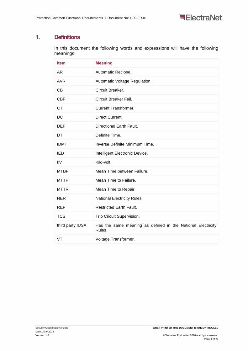
1. Definitions
In this document the following words and expressions will have the following meanings:
Item Meaning
AR Automatic Reclose.
AVR Automatic Voltage Regulation.
CB Circuit Breaker.
CBF Circuit Breaker Fail.
CT Current Transformer.
DC Direct Current.
DEF Directional Earth Fault.
DT Definite Time.
IDMT Inverse Definite Minimum Time.
IED Intelligent Electronic Device.
kV Kilo-volt.
MTBF Mean Time between Failure.
MTTF Mean Time to Failure.
MTTR Mean Time to Repair.
NER National Electricity Rules.
REF Restricted Earth Fault.
TCS Trip Circuit Supervision.
third party IUSA Has the same meaning as defined in the National Electricity Rules
VT Voltage Transformer.
Protection Common Functional Requirements l Document No: 1-09-FR-01
Security Classification: Public WHEN PRINTED THIS DOCUMENT IS UNCONTROLLED
Date: June 2018
Version: 1.0 ©ElectraNet Pty Limited 2018 – all rights reserved
Page 5 of 22
2. Purpose
This document details the common functional requirements for ElectraNet’s protection systems.
3. Scope
This document defines the common functional requirements for all protection systems applied to ElectraNet’s 275 kV, 132 kV and 66 kV transmission network assets including transformer low voltage and tertiary voltage connections. The individual requirements for specific protection systems are detailed within the relevant, specific protection system documents. The setting of protection systems is defined within 1-09-AG-02 Protection and Control Setting Application Guide.
Protection Common Functional Requirements l Document No: 1-09-FR-01
Security Classification: Public WHEN PRINTED THIS DOCUMENT IS UNCONTROLLED
Date: June 2018
Version: 1.0 ©ElectraNet Pty Limited 2018 – all rights reserved
Page 6 of 22
4. Referenced Documents
The table below lists applicable legislations, standards, referenced documents:
Legislation
NER National Electricity Rules
SAEA Electricity Act 1996 (SA)
TC/08 Electricity Transmission Code
ElectraNet’s Documentation
1-09-ACS Protection System – Digital
1-09-FR-02 Feeder Differential Protection
1-09-FR-03 Feeder Distance Protection
1-09-FR-04 Non-Feeder Differential Protection
1-09-FR-05 Thermal Overload Protection
1-09-FR-06 Overcurrent Protection
1-09-FR-07 Overvoltage and Loss of Voltage Protection
1-09-FR-08 Mechanical Protection
1-09-FR-09 Protection Signalling and Intertripping
1-09-FR-10 Circuit Breaker Fail
1-09-FR-13 Trip Circuit Supervision
1-09-FR-15 Synchronising
1-09-FR-17 Auto-reclose Switching
1-09-FR-18 Automatic Voltage Regulation
1-09-FR-26 Cubicles and Panels
1-09-FR-28 Equipment Hardware and Software
1-11-ADM-27 Air Insulated HV Current Transformers
Protection Common Functional Requirements l Document No: 1-09-FR-01
Security Classification: Public WHEN PRINTED THIS DOCUMENT IS UNCONTROLLED
Date: June 2018
Version: 1.0 ©ElectraNet Pty Limited 2018 – all rights reserved
Page 7 of 22
5. Functional Requirements
5.1 Safety Requirements
Protection systems are classified, by ElectraNet, as safety critical systems and consequently must be designed such that no single component failure will prevent the protection system from operating when it is required to do so.
Informative: In the context of this document structure, failure shall mean failure to operate, or failure to operate within a specified maximum operating time, or in a time whereby other protection has sufficient time to perform a correct back-up function.
5.2 Planning and Design Requirements
5.2.1 General Requirements
5.2.1.1 Protection System Philosophy
Protection systems must be designed such that all power system faults are detected by at least two independent, high speed main protection systems, designated as Set X and Set Y. The outputs of the protection systems must be selectively allocated to independent tripping systems supplied from separate direct current (DC) systems. The Set X and Set Y protection systems must avoid the use of common hardware and common software in order to minimise the risk of common mode failure and common setting error. To cater for the failure of downstream protection systems, back-up protection functionality must be provided within both Set X and Set Y protection systems. In addition, duplicated circuit breaker failure (CBF) protection must be provided to clear faults occurring within dead zones and to cater for the failure of circuit breakers and their associated tripping systems. The circuit breaker failure protection must be arranged to trip and transfer trip all contiguous circuit breakers.
Informative: A dead zone occurs within a substation between a protection zone and a circuit breaker adjacent to that protection zone that is required to open and clear the fault.
5.2.1.2 Protection System Selectivity
In the event of a power system fault occurring on the equipment that the protection systems are deployed to protect, both Set X and Set Y protection systems are required to rapidly detect the fault and initiate the opening of all the circuit breakers that are required to be opened in order to isolate the faulted equipment from the power system. Protection systems must be capable of discriminating between faults occurring on an adjacent items of equipment and faults occurring on the item of equipment they are deployed to protect.
5.2.1.3 Protection System Sensitivity
Protection systems must be configured to clear all faults occurring on the equipment they are deployed to protect whilst remaining secure under all rated loading conditions.
Protection Common Functional Requirements l Document No: 1-09-FR-01
Security Classification: Public WHEN PRINTED THIS DOCUMENT IS UNCONTROLLED
Date: June 2018
Version: 1.0 ©ElectraNet Pty Limited 2018 – all rights reserved
Page 8 of 22
5.2.1.4 Protection System Operating Time
Protection systems must be designed such that the total fault clearance times are in accordance with the maximum fault clearance times specified within the current version of the National Electricity Rules (NER).
5.2.1.5 Protection Trip Outputs
All protection trip outputs must be configured for unlatched operation.
5.2.1.6 Equipment Technology
ElectraNet’s protection systems shall be established utilising microprocessor based equipment that is capable of providing integrated functionality, a high degree of self-supervision, event recording, oscillography and information exchange via communication channels. Electromechanical and static analogue electronic based protection systems must not be deployed. The requirements for equipment hardware platforms are specified within 1-09-FR-28 Equipment Hardware and Software.
5.2.1.7 Setting Group Definitions
All protection systems must be capable of supporting a minimum of four user defined setting groups, configured to be applied as the follows:
a) Setting Group 1 must be applied for power system normal conditions;
b) Setting Group 2 must be applied for power system abnormal conditions;
c) Setting Group 3 must be applied for commissioning activities; and
d) Setting Group 4 must be reserved for special applications and configured as Setting Group 1 when no such applications are specified within the contract-specific documentation.
5.2.2 Feeder Protection Systems
For all feeder protection applications, redundant Set X and Set Y feeder protection systems must be arranged to operate on an either-one-out-of-two tripping philosophy. Each of the Set X and Set Y feeder protection systems must incorporate the following functionality:
a) Main Protection;
b) Direct Transfer Trip Send and Direct Transfer Trip Receive;
c) Back-up Protection;
d) Directional Earth Fault (DEF) Protection;
e) CBF Protection (for both controlling circuit breakers);
f) Stub Bus Protection;
g) Fault Location; and
h) Automatic Reclose (AR) Initiation and Blocking.
Protection Common Functional Requirements l Document No: 1-09-FR-01
Security Classification: Public WHEN PRINTED THIS DOCUMENT IS UNCONTROLLED
Date: June 2018
Version: 1.0 ©ElectraNet Pty Limited 2018 – all rights reserved
Page 9 of 22
5.2.2.1 Main Protection
The preferred feeder main protection arrangement is for both Set X and Set Y protection systems to employ current differential protection schemes in accordance with the requirements specified within 1-09-FR-02 Feeder Differential Protection. An alternative arrangement for Set X to employ a current differential protection scheme and for Set Y to employ a communications aided distance protection scheme. The requirements of the distance protection scheme are specified within 1-09-FR-03 Feeder Distance Protection. Both the current differential and distance protection schemes must be capable of directly transferring a local trip signal to the remote end via associated communication channels. ElectraNet will specify, within the contract-specific documentation, which of the two feeder main protection arrangements should be deployed.
5.2.2.2 Exclusion of Current Differential Protection
Feeder current differential protection schemes must be deployed for all feeder main protection systems except where suitable communication channels are not available. Under this situation, distance protection scheme(s) must be deployed.
5.2.2.3 Exclusion of Distance Protection
The circumstances in which distance protection schemes must not be deployed as a feeder main protection system are:
a) On feeders where duplicate current differential protection can be deployed;
b) On feeders not equipped with three phase voltage transformers;
c) On feeders that are either compensated by series capacitors or adjacent to feeders that are compensated by series capacitors; or
d) On feeders of insufficient electrical length to allow a distance protection scheme to comply with the selectivity requirements of Section 5.2.1.2.
5.2.2.4 Direct Transfer Trip
To ensure faults are selectively isolated under all fault levels, on both interconnected and radial feeders, the main protection must, on detection of faults, transfer phase segregated direct trip signals to the remote end(s). Back-up protection and circuit breaker failure protection must transfer three phase direct trip signals to the remote end(s). The requirements for protection signalling are specified within 1-09-FR-09 - Protection Signalling and Intertripping.
5.2.2.5 Back-up Protection
Time-stepped and overreached distance protections must be applied as feeder back-up protection. Within feeder current differential protection systems, this arrangement must be permanently activated.
In applications where back-up distance protection cannot be deployed, a 3-phase overcurrent protection with a definite time (DT) characteristic must be applied as the back-up protection. The requirements of 3 phase overcurrent protection are specified within 1-09-FR-06 Overcurrent Protection.
Protection Common Functional Requirements l Document No: 1-09-FR-01
Security Classification: Public WHEN PRINTED THIS DOCUMENT IS UNCONTROLLED
Date: June 2018
Version: 1.0 ©ElectraNet Pty Limited 2018 – all rights reserved
Page 10 of 22
5.2.2.6 Commissioning Overcurrent (Setting Group 3)
Each 3-phase current transformer input for the protected feeder must be equipped with instantaneous overcurrent elements connected prior to any internal summation. The elements must be enabled through the selection of Setting Group 3.
5.2.2.7 Directional Earth Fault Protection
Where the sensitivity requirements defined within Section 5.2.1.3 cannot be achieved, the main protection must be supplemented by the addition of a directional earth fault protection scheme based on DT overcurrent protection. The DEF protection scheme must be arranged to co-ordinate selectively with the main protection. The requirements for overcurrent derived DEF protection are specified within 1-09-FR-06 Overcurrent Protection.
5.2.2.8 Stub Bus Protection
The purpose of stub bus protection is to isolate faults which occur between the feeder’s current transformers and the open line disconnector. The preferred arrangement for stub protection is to be integrated into the feeder main protection system’s differential or distance protection functions. Where this cannot be achieved, stub protection must be based on an overcurrent function with Inverse Definite Minimum Time (IDMT) characteristic. The requirements for overcurrent derived stub protection are specified within 1-09-FR-06 Overcurrent Protection. Stub bus protection must be conditioned by the line disconnector status and must only be active when the line disconnector is in the open status.
5.2.2.9 Circuit Breaker Failure Protection
Phase segregated, current and status checked CBF protection must be located within the feeder protection system for each of the feeder’s controlling circuit breakers. The requirements for CBF protection are specified within 1-09-FR-10 Circuit Breaker Failure Protection.
5.2.2.10 Fault Location
At least one set of feeder protection systems must provide fault location facilities on the protected line with the accuracy of better than 5% of feeder length.
5.2.2.11 Circuit Breaker Auto Reclose Initiation and Blocking
AR initiation and blocking functions must satisfy the following requirements:
a) AR functions must be initiated by the reset of feeder main protection operations resulting from single phase to ground faults; and
b) All protection functions, other than clause 5.2.2.11(a) must block AR systems.
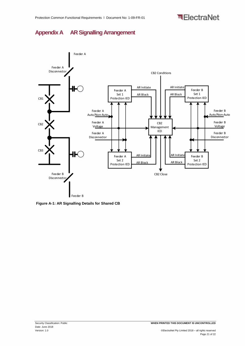
The requirements for the AR function are specified within 1-09-FR-02 Feeder Differential Protection, 1-09-FR-03 Feeder Distance Protection and 1-09-FR-17 Automatic Reclose Switching documents respectively. The signalling requirements between feeder protection systems and CB management systems, associated with shared circuit breakers, are appended to this document.
Protection Common Functional Requirements l Document No: 1-09-FR-01
Security Classification: Public WHEN PRINTED THIS DOCUMENT IS UNCONTROLLED
Date: June 2018
Version: 1.0 ©ElectraNet Pty Limited 2018 – all rights reserved
Page 11 of 22
5.2.3 Circuit Breaker Management Systems
A circuit breaker management system must be deployed for each circuit breaker. The circuit breaker management system must consist of a multifunction IED and a single function device. The single function device must provide the trip circuit supervision (TCS) function for the Set Y trip system. The multifunction IED must incorporate the following functionality:
a) Synchronising;
b) AR; and
c) TCS for the Set X trip system.
5.2.3.1 Synchronising Function
The synchronising function must be utilised for both automatic and manual closing of a circuit breaker. The requirements for the synchronising function are specified within 1-09-FR-15 Synchronising document.
5.2.3.2 AR Function
The AR must be implemented within the circuit breaker management IED and must be performed in conjunction with the AR initiate and AR block signals initiated from feeder protection systems according to Section 5.2.2.11. The AR function must satisfy the following requirements:
a) AR functions must be limited to a single re-close attempt, power system faults occurring within the reclaim time must result in a reclose lockout condition;
b) AR functions must be capable of being manually switched in and out of service;
c) AR functions must be blocked immediately following CB supervisory close operations; and
d) AR functions must be applied to both single pole and three pole circuit breakers (CBs).
a) The requirements for AR function are specified within 1-09-FR-17 Auto-reclose Switching
Informative: The reclaim time is a period which is commenced following a circuit breaker re-close.
5.2.3.3 Trip Circuit Supervision Function
TCS must be applied to every circuit breaker trip system and must monitor the trip supply, trip circuit wiring, trip circuit field cables and CB trip coil. Trip systems must be monitored with the CB in both the open and closed positions. In the event of a trip circuit failure the TCS must initiate local and remote alarms. The requirements for TCS function are specified within 1-09-FR-13 Trip Circuit Supervision.
5.2.4 Transformer Protection Systems
For all transformer protection applications, redundant Set X and Set Y transformer protection systems must be arranged to operate on an either-one-
Protection Common Functional Requirements l Document No: 1-09-FR-01
Security Classification: Public WHEN PRINTED THIS DOCUMENT IS UNCONTROLLED
Date: June 2018
Version: 1.0 ©ElectraNet Pty Limited 2018 – all rights reserved
Page 12 of 22
out-of-two tripping philosophy. Each of the Set X and Set Y transformer protection systems must incorporate the following functionality:
a) Main Protection;
b) Back-up Protection;
c) Mechanical Protection Management;
d) Neutral Overcurrent Protection;
e) Overload Protection;
f) Tertiary Winding Protection;
g) Auxiliary Transformer Protection; and
h) High Side CBF Protection.
5.2.4.1 Main Protection
The main protection arrangement must comprise of a phase segregated, two stage differential protection scheme. Stage 1 must be a load restrained, low set differential protection function. Stage 2 protection must be an unrestrained, high set differential protection function. Highset instantaneous overcurrent protection may be applied as a substitute to unrestrained, high set differential protection. In applications where transformer secondary windings are non-effectively earthed the differential protection must be supplemented by the application of Restricted Earth Fault (REF) protection. The requirements for transformer differential protection are specified within 1-09-FR-04 Non-feeder Differential Protection.
5.2.4.2 Back-up Protection
Three phase overcurrent protection with IDMT characteristic must be applied to transformer high side as back-up protection. An additional neutral overcurrent protection with DT or IDMT characteristic must be applied to transformer low side neutral connection as a backup protection. The backup phase protection must be arranged to operate selectively with the overload protection specified within Section 5.2.4.5. The detailed requirements for phase and neutral overcurrent protection are specified within 1-09-FR-06 Overcurrent Protection.
5.2.4.3 Mechanical Protection Management
Transformer protection systems must initiate protection trips based on the received operation signals from transformer mechanical protection devices.
Each of Set X and Set Y protection systems must be equipped with sufficient optical inputs to manage two Buchholz relay trips, three winding temperature trips, one oil temperature trip and one pressure relief device trip. The detailed requirements for mechanical protection are specified within 1-09-FR-08 Mechanical Protection.
5.2.4.4 Neutral Overcurrent Protection
For the transformers with low side windings earthed through a resistance or reactance, protection of the neutral earthing resistor or reactor must be provided by a single overcurrent element with DT or IDMT characteristic. The overcurrent element must be supplied from a current transformer mounted on the low side
Protection Common Functional Requirements l Document No: 1-09-FR-01
Security Classification: Public WHEN PRINTED THIS DOCUMENT IS UNCONTROLLED
Date: June 2018
Version: 1.0 ©ElectraNet Pty Limited 2018 – all rights reserved
Page 13 of 22
winding’s neutral connection. The requirements for neutral overcurrent are specified within 1-09-FR-06 Overcurrent Protection.
5.2.4.5 Overload Protection
Three phase overcurrent with DT characteristic must be applied to the low side of transformer as overload protection. The overload protection must be arranged to operate selectively with the high side back-up protection as specified within Section 5.2.4.2. The requirements for 3-phase high side overcurrent protection are specified within 1-09-FR-06 Overcurrent Protection.
5.2.4.6 Tertiary Winding Protection
For the transformers that are equipped with a stabilising winding, the preferred protection arrangement for the tertiary winding is to be integrated into the transformer main differential protection. Discreet tertiary earth fault protection must only be applied in instances where the differential protection is unable to provide the required sensitivity to adequately protect tertiary winding. Where discreet tertiary winding protection is required, it must be provided by an overcurrent function with IDMT characteristic supplied from a current transformer mounted on the tertiary winding’s earth connection. The requirements for overcurrent derived tertiary winding protection are specified within 1-09-FR-06 Overcurrent Protection.
5.2.4.7 Auxiliary Transformer Protection
Tertiary connected auxiliary transformers must be included within the transformer main protection zone, unless:
a) Faults on the low side of auxiliary transformer terminals would cause operation of the power transformer main protection; or
b) The auxiliary transformer rating exceeds 2% of the transformer rating.
Under the above circumstances, the auxiliary transformers must be equipped with overcurrent devices, which run IDMT characteristic, fitted on both its high side and low side. ElectraNet shall specify, on an individual contract basis, where auxiliary transformers must be excluded from the main protection zone.
5.2.4.8 High Side CBF Protection
Three phase current and status checked CB failure protection must be located within the transformer protection system for each of the transformer high side controlling circuit breakers. The requirements of circuit breaker failure protection are specified within 1-09-FR-10 Circuit Breaker Failure.
5.2.5 Transformer Low Side Protection Systems
The transformer low side protection systems must consist of redundant Set X and Set Y multifunction IEDs. The protection systems must be arranged to operate on an either-one-out-of-two tripping philosophy. Each of the Set X and Set Y transformer protection systems must incorporate the following functionality:
a) CBF Protection; and
b) TCS Monitoring.
Protection Common Functional Requirements l Document No: 1-09-FR-01
Security Classification: Public WHEN PRINTED THIS DOCUMENT IS UNCONTROLLED
Date: June 2018
Version: 1.0 ©ElectraNet Pty Limited 2018 – all rights reserved
Page 14 of 22
5.2.5.1 CBF Protection
Three phase current and status checked circuit breaker failure protection must be applied for each of the transformer low side controlling circuit breakers. The requirements of circuit breaker failure protection are specified within 1-09-FR-10 Circuit Breaker Failure.
5.2.5.2 TCS Function
TCS must be applied to the low side circuit breaker trip systems and must monitor the trip supply, trip circuit wiring, trip circuit field cables and CB trip coil. Trip systems must be monitored with the CB in both the open and closed positions. In the event of a trip circuit failure the TCS must initiate local and remote alarms. The requirements for TCS function are specified within 1-09-FR-13 Trip Circuit Supervision.
5.2.6 Reactor Protection Systems
For all reactor protection applications, redundant Set X and Set Y reactor protection systems must be arranged to operate on an either-one-out-of-two tripping philosophy. Each of the Set X and Set Y reactor protection systems must incorporate the following functionality:
a) Main Protection;
b) Mechanical Protection Management; and
c) CBF Protection.
5.2.6.1 Main Protection
The main protection arrangement must comprise of a phase segregated, two stage differential protection scheme. Stage 1 must be a load restrained, low set differential protection function. Stage 2 protection must be an unrestrained, high set differential protection function. Highset instantaneous overcurrent protection may be applied as a substitute to unrestrained, high set differential protection. The requirements for reactor differential protection are specified within 1-09-FR-04 Non-feeder Differential Protection.
5.2.6.2 Mechanical Protection Management
Reactor protection systems must initiate protection trips based on the received operation signals from reactor mechanical protection devices.
Each of Set X and Set Y protection systems must be equipped with sufficient optical inputs to manage two Buchholz relay trips, one winding temperature trips, one oil temperature trip and one pressure relief device trip. The detailed requirements for mechanical protection are specified within 1-09-FR-08 Mechanical Protection.
5.2.6.3 CBF Protection
Three phase current and status checked circuit breaker failure protection must be located within the reactor protection systems for its controlling circuit breaker. The requirements of circuit breaker failure protection are specified within 1-09-FR-10 Circuit Breaker Failure.
Protection Common Functional Requirements l Document No: 1-09-FR-01
Security Classification: Public WHEN PRINTED THIS DOCUMENT IS UNCONTROLLED
Date: June 2018
Version: 1.0 ©ElectraNet Pty Limited 2018 – all rights reserved
Page 15 of 22
5.2.7 Bus Protection Systems
For all bus protection applications, redundant Set X and Set Y bus protection systems must be arranged to operate on an either-one-out-of-two tripping philosophy. Each of the Set X and Set Y bus protection systems must incorporate the following functionality:
a) Main Protection; and
b) CBF Protection.
5.2.7.1 Main Protection
The main protection arrangement must comprise of a phase segregated, two stage differential protection scheme. Stage 1 protection must be a load restrained, low set differential protection function. Stage 2 protection must be an unrestrained, high set differential protection function. Highset instantaneous overcurrent protection may be applied as a substitute to unrestrained, high set differential protection. The requirements for bus differential protection are specified within 1-09-FR-04 Non-feeder Differential Protection.
5.2.7.2 CBF Protection
Three phase current and status checked circuit breaker failure protection must be located within the bus protection system for the each circuit breaker connected to the protected bus. The requirements of circuit breaker failure protection are specified within 1-09-FR-10
5.2.8 Capacitor Bank Protection Systems
For all capacitor bank protection applications, redundant Set X and Set Y capacitor bank protection systems must be arranged to operate on an either-one-out-of-two tripping philosophy. Each of the Set X and Set Y capacitor bank protection systems must incorporate the following functionality:
a) Overcurrent Protection;
b) Overvoltage Protection;
c) Dead Bus Protection; and
d) CBF Protection.
5.2.8.1 Overcurrent Protection
The following overcurrent protection must provide the following functionality:
a) An unbalance overcurrent protection function with DT characteristic according to 1-09-FR-06 Overcurrent Protection;
b) A three phase overcurrent protection function with DT characteristic according to 1-09-FR-06 Overcurrent Protection;
c) A Harmonic overcurrent protection function with DT characteristic according to 1-09-FR-05 Thermal Overload Protection; and
d) A dead bus protection function.
Protection Common Functional Requirements l Document No: 1-09-FR-01
Security Classification: Public WHEN PRINTED THIS DOCUMENT IS UNCONTROLLED
Date: June 2018
Version: 1.0 ©ElectraNet Pty Limited 2018 – all rights reserved
Page 16 of 22
5.2.8.2 Overvoltage Protection
Voltage protection arrangement must be provided by the following functionalities according to 1-09-FR-07 Overvoltage and Loss of Voltage Protection:
a) An overvoltage protection function with definite time delay;
b) A harmonic overvoltage protection function; and
c) A dead bus protection function.
5.2.8.3 Dead Bus Protection
Dead bus protection may be supplied from voltage or current references, and consequently may be included in either the overcurrent or overvoltage protection scheme. The dead bus protection must be arranged to trip the capacitor bank on loss of supply, following a short delay.
5.2.8.4 CBF Protection
Three phase current and status checked circuit breaker failure protection must be located within the capacitor bank’s protection systems for its controlling circuit breaker. The requirements of circuit breaker failure protection are specified within 1-09-FR-10 Circuit Breaker Failure.
5.2.9 Automatic Voltage Regulation (AVR) Systems
An AVR system must be provided at every third party connection point on ElectraNet’s transmission network, in order to maintain the required bus voltage level. The detailed requirements of the function are specified in 1-09-FR-18 Automatic Voltage Regulation.
5.3 Constructability Requirements
The protection system must be designed with the following features:
a) Each protection device must be designed such that its input / output capability is expandable. The preferred method of expansion is through the addition of modular input / output boards. Protection systems that do not support the expansion of input / outputs must be equipped a minimum of two normally open spare output contacts and two spare digital inputs;
b) Hardware and software requirements as defined within 1-09-FR-28 Equipment Hardware and Software;
c) Accommodation requirements as defined within 1-09-FR-26 Cubicles and Panels;
d) Circuitry and connections requirements as defined within 1-09-FR-27 Circuitry; and
e) Clearly labelled test and isolation facilities must be provided at the front of protection and control cubicles with clear labels1-09-FR-26 Cubicles and Panels and 1-09-FR-27 Circuitry.
Protection Common Functional Requirements l Document No: 1-09-FR-01
Security Classification: Public WHEN PRINTED THIS DOCUMENT IS UNCONTROLLED
Date: June 2018
Version: 1.0 ©ElectraNet Pty Limited 2018 – all rights reserved
Page 17 of 22
5.4 Maintainability Requirements
Protection systems must be designed with the maintenance facilities described below:
a) Each protection device must be equipped with self-monitoring and diagnostic capabilities to minimise hidden failures;
b) Where equipment incorporates firmware, a unique number, traceable to the release of the firmware and the version of the system to which it pertains, must be clearly marked on the component, or be available from the informative interface, as well as being documented in the instruction manual;
c) Maintenance aids such as printed wiring extension boards, jumper leads and other special tools must be provided;
d) Each protection device, which is in service, must be capable of being safely and individually isolated from the rest of secondary system without the need for primary system outages, specialist tools and knowledge. This requirement extends to current transformer circuits, voltage transformer circuits, DC supplies and control and tripping circuits;
e) If the device, which is to be isolated, is connected to other device(s) to form a protection scheme (e.g. feeder protection), the isolation must be conditioned with the isolation status of the remotely connected device(s);
f) Each protection device must be capable of being tested by analogue and digital injections from an external test set after being isolated from the rest of secondary system. This requirement is also extended to the ability to monitor communication messages to the substation automation system;
g) A live trip test facility, which operates the selected phase of the selected circuit breaker, must be provided for each protection device;
h) The live trip test facility must not initiate CBF functions;
i) The live trip test facility must initiate Automatic Reclose (AR) function for the selected phase of the selected circuit breaker; and
j) If a protection device becomes defective, the failed equipment must be capable of being removed and replaced without primary system outages.
5.5 Operability Requirements
The protection system must be designed with the following functionality:
a) Power System Conditions
The protection system must be designed to perform correctly for all foreseeable conditions which may occur on the power system condition, which includes:
(i) Variable fault current contributions;
(ii) Variable X/R ratios;
(iii) Balanced and unbalanced circuit loading;
(iv) Under and over voltages;
(v) Shunt capacitance currents;
Protection Common Functional Requirements l Document No: 1-09-FR-01
Security Classification: Public WHEN PRINTED THIS DOCUMENT IS UNCONTROLLED
Date: June 2018
Version: 1.0 ©ElectraNet Pty Limited 2018 – all rights reserved
Page 18 of 22
(vi) Harmonic currents;
(vii) Oscillatory currents;
(viii) Various resonance conditions; and
(ix) Travelling wave effects.
No component of the protection system, must mal-operate during primary equipment energisation or de-energisation. This requirement must be met without the use of additional guard relays or additional time delays that could degrade protection dependability.
b) Current Transformer (CT) Saturation
Although the CTs specified in 1-11-ADM-27 Air Insulated HV Current Transformers are designed not to saturate, remnant flux could in some circumstances cause a degree of saturation during fault conditions. Some tolerance to CT saturation is therefore required during protection system design.
5.6 Availability Requirements
The protection scheme design must comply with the availability requirements listed in 1-09-ACS-01 Protection System – Digital. The relay must clearly state the mean time between failure (MTBF) and mean time to repair (MTTR) for each device.
5.7 Reliability Requirements
The protection scheme design must comply with the availability requirements listed in 1-09-ACS-01 Protection System – Digital. The relay supplier shall clearly state the mean time to failure (MTTF) for each device.
5.8 Testing and Validation Requirements
Each secondary system device must comply with the requirement listed in 1-09-FR-28 Equipment Hardware and Software.
6. SAP Data Capture Requirements
The following information on each protection devices is required to be captured in SAP or relevant software database:
a) Installed location;
b) Functional location identifier;
c) Description text;
d) Make/manufacturer;
e) Model number;
f) Manufacturer part number;
g) Manufacturer serial number;
h) Acquisition date;
Protection Common Functional Requirements l Document No: 1-09-FR-01
Security Classification: Public WHEN PRINTED THIS DOCUMENT IS UNCONTROLLED
Date: June 2018
Version: 1.0 ©ElectraNet Pty Limited 2018 – all rights reserved
Page 19 of 22
i) Start-up date; and
j) ElectraNet’s barcode/inventory number.

Protection Common Functional Requirements l Document No: 1-09-FR-01
Security Classification: Public WHEN PRINTED THIS DOCUMENT IS UNCONTROLLED
Date: June 2018
Version: 1.0 ©ElectraNet Pty Limited 2018 – all rights reserved
Page 20 of 22
Appendices
Protection Common Functional Requirements l Document No: 1-09-FR-01
Security Classification: Public WHEN PRINTED THIS DOCUMENT IS UNCONTROLLED
Date: June 2018
Version: 1.0 ©ElectraNet Pty Limited 2018 – all rights reserved
Page 21 of 22
Appendix A AR Signalling Arrangement
CB1
CB2
CB3
Feeder ADisconnector
Feeder BDisconnector
Feeder A
Feeder B
Feeder ASet 1
Protection IED
Feeder BSet 1
Protection IED
Feeder ASet 2
Protection IED
Feeder BSet 2
Protection IED
CB2 Management
IED
Feeder AAuto/Non-Auto
Feeder AVoltage
Feeder ADisconnector
Feeder BAuto/Non-Auto
Feeder BVoltage
Feeder BDisconnector
CB2 Conditions
CB2 Close
AR Initiate
AR Block
AR Initiate
AR Block
AR Initiate
AR Block
AR Initiate
AR Block
Figure A-1: AR Signalling Details for Shared CB