Embed Size (px)
Citation preview
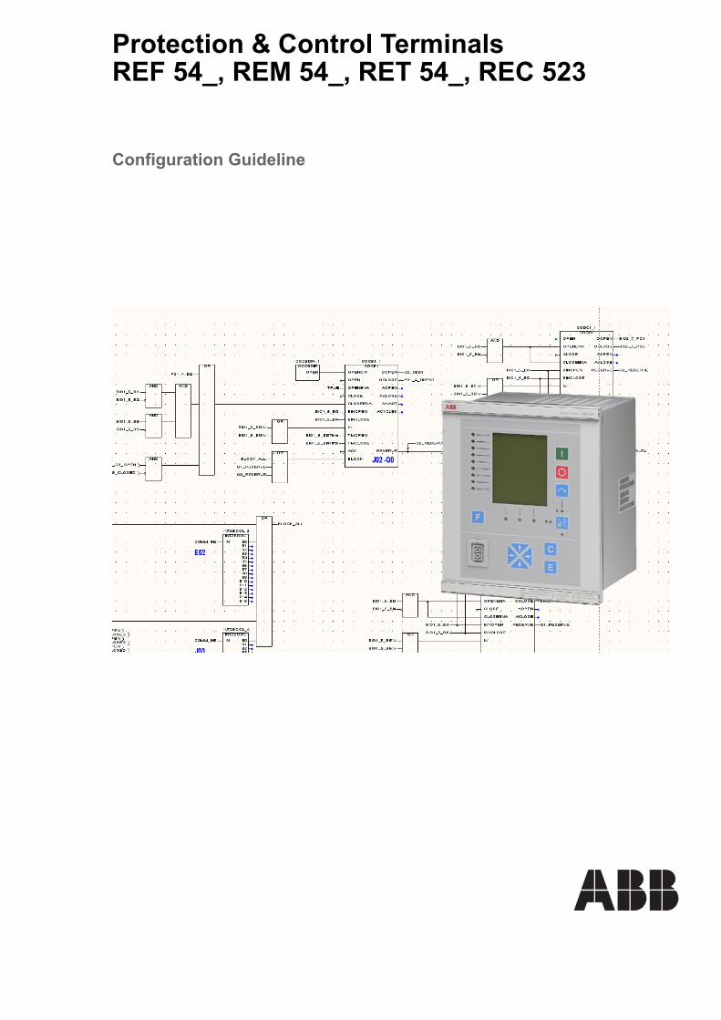
Protection & Control TerminalsREF 54_, REM 54_, RET 54_, REC 523
Configuration Guideline

Protection & Control Terminals Configuration Guideline
REF 54_, REM 54_,RET 54_, REC 523
1MRS750745-MUM
Issued: 20.10.1998Version: L/08.07.2005
Contents1. About this manual .....................................................................7
1.1. Copyrights .....................................................................................71.2. Trademarks ...................................................................................71.3. General .........................................................................................71.4. Use of symbols ..............................................................................81.5. Document conventions ..................................................................91.6. Abbreviations ................................................................................91.7. Terminology ..................................................................................91.8. Related documents .....................................................................101.9. Document revisions .....................................................................11
2. Safety information ...................................................................133. Relay Configuration Tool .......................................................154. Specification for relay configuration .....................................175. Editing the relay configurations ............................................19
5.1. Getting started .............................................................................195.1.1. Libraries ...........................................................................195.1.2. Program organisation unit ................................................215.1.3. Logical POUs ...................................................................235.1.4. Physical hardware ............................................................25
5.1.4.1. Configuration ......................................................265.1.4.2. Resource for REF 54_, REM 54_
and REC 523 ......................................................275.1.4.3. Resource for REF 54_ Release 2.5 or later,
REC 523 revision F and RET 54_ 375.1.4.4. Tasks ..................................................................47
5.2. Declaring variables ......................................................................495.2.1. Global variables ...............................................................525.2.2. Local variables .................................................................52
5.3. Compiling project ........................................................................575.4. Add-on protocol ...........................................................................575.5. Downloading the configuration ....................................................57
5.5.1. REF 54_ Release 2.5, RET 54_ and REC 523 revision F additions ..........................................59
6. Main configuration rules ........................................................636.1. General .......................................................................................636.2. Digital inputs and outputs ............................................................636.3. Explicit feedback path .................................................................646.4. Analog inputs ..............................................................................656.5. Error outputs of application function blocks ................................66
©Copyright 2005 ABB Oy, Distribution Automation, Vaasa, FINLAND 3
1MRS750745-MUMProtection & Control Terminals Configuration Guideline
REF 54_, REM 54_, RET 54_, REC 523
6.6. Warnings ..................................................................................... 676.7. Execution order ........................................................................... 676.8. F-key ........................................................................................... 68
7. Engineering tips ..................................................................... 717.1. Horizontal communication .......................................................... 71
7.1.1. Guideline for using LON NV-variables in PLC logic ......... 717.1.1.1. COMM_IN .......................................................... 717.1.1.2. COMM_OUT ...................................................... 727.1.1.3. Cyclic sending generation .................................. 737.1.1.4. Cyclic communication check .............................. 747.1.1.5. Blocking ............................................................. 747.1.1.6. Control of objects ............................................... 757.1.1.7. Bypass mode ..................................................... 76
7.2. Events from the measurement function blocks ........................... 76
8. APPENDIX A: Relay configuration procedure ..................... 779. APPENDIX B: Specification for REF 54_ feeder
terminal configuration 799.1. General data ............................................................................... 799.2. Electrotechnical data .................................................................. 80
9.2.1. Analog inputs ................................................................... 809.2.2. System frequency ............................................................ 829.2.3. Digital inputs .................................................................... 829.2.4. Digital outputs .................................................................. 849.2.5. RTD module .................................................................... 88
9.2.5.1. RTD/analog inputs ............................................. 889.2.5.2. RTD outputs ....................................................... 89
9.3. Functionality ................................................................................ 899.3.1. Order number .................................................................. 899.3.2. Application function blocks used ..................................... 909.3.3. Communication ................................................................ 91
9.4. Relay MIMIC configuration ......................................................... 939.4.1. Illustration of the system, MIMIC diagram ....................... 939.4.2. Alarm LEDs ..................................................................... 94
9.5. Functionality logic ....................................................................... 959.6. Feeder terminal settings ............................................................. 96
10.APPENDIX C: Specification for REM 54_ machine terminal configuration 9710.1.General data .............................................................................. 9710.2.Electrotechnical data .................................................................. 97
10.2.1.Analog inputs ................................................................... 97
4
1MRS750745-MUM REF 54_, REM 54_,RET 54_, REC 523
Protection & Control Terminals Configuration Guideline
10.2.1.1.Hardware versions with 5 current and 4 voltage transformers 97
10.2.1.2.Hardware versions with 6 current and 3 voltage transformers 98
10.2.1.3.Hardware versions with 7 current and 2 voltage transformers 99
10.2.1.4.Hardware versions with 8 current and 1 voltage transformer 101
10.2.1.5.Sensor inputs ...................................................10210.2.2.System frequency ..........................................................10210.2.3.Digital inputs ..................................................................10310.2.4.Digital outputs ................................................................10510.2.5.RTD module ...................................................................108
10.2.5.1.RTD/analog inputs ...........................................10810.2.5.2.RTD outputs .....................................................109
10.3.Functionality .............................................................................10910.3.1.Order number .................................................................10910.3.2.Application function blocks used ................................11010.3.3.Communication ..............................................................111
10.4.Relay MIMIC configuration .......................................................11210.4.1.Illustration of the system, MIMIC diagram ......................11210.4.2.Alarm LEDs ....................................................................113
10.5.Functionality logic .....................................................................11410.6.Machine terminal settings .........................................................115
11.APPENDIX D: Specification for RET 54_ transformer terminal configuration .....................................11711.1.General data .............................................................................11711.2.Electrotechnical data ................................................................118
11.2.1.Analog inputs .................................................................11811.2.1.1.Hardware versions with 6 current
and 3 voltage transformers 11811.2.1.2.Hardware versions with 7 current
and 2 voltage transformers 11911.2.1.3.Hardware versions with 8 current
and 1 voltage transformer 12011.2.2.System frequency ..........................................................12011.2.3.Digital inputs ..................................................................12111.2.4.Digital outputs ................................................................12311.2.5.RTD module ...................................................................126
11.2.5.1.RTD/analog inputs ...........................................12611.2.5.2.RTD outputs .....................................................127
11.3.Functionality .............................................................................12711.3.1.Order number .................................................................127
5
1MRS750745-MUMProtection & Control Terminals Configuration Guideline
REF 54_, REM 54_, RET 54_, REC 523
11.3.2.Application function blocks used ................................... 12811.3.3.Communication .............................................................. 129
11.4.Relay MIMIC configuration ....................................................... 13011.4.1.Illustration of the system, MIMIC diagram ..................... 13011.4.2.Alarm LEDs ................................................................... 131
11.5.Functionality logic ..................................................................... 13211.6.Transformer terminal settings .................................................. 133
12.APPENDIX E: Specification for REC 523 Remote Monitoring and Control Unit configuration 13512.1.General data ............................................................................ 13512.2.Electrotechnical data ................................................................ 136
12.2.1.Analog inputs ................................................................. 13612.2.2.System frequency .......................................................... 14012.2.3.Digital inputs .................................................................. 14112.2.4.Digital outputs ................................................................ 142
12.3.Functionality ............................................................................. 14312.3.1.Order number ................................................................ 14312.3.2.Application function blocks used ................................... 14312.3.3.Communication .............................................................. 144
12.4.Virtual channels ........................................................................ 14412.4.1.LED configuration .......................................................... 144
12.5.Remote monitoring and control unit settings ............................ 146
13.APPENDIX F: Power quality application guide for harmonics 14713.1.Power quality and harmonics ................................................... 14713.2.Background for harmonics ....................................................... 14713.3.Harmonic sources .................................................................... 149
13.3.1.Single-phase power supplies ......................................... 14913.3.2.Three-phase power converters ...................................... 15013.3.3.Other harmonic sources ................................................ 151
13.4.System response characteristics ............................................. 15213.5.Effects of harmonics ................................................................. 15413.6.Applications for harmonic measurements ................................ 155
13.6.1.Power quality and harmonics ......................................... 15513.6.2.Harmonic monitoring with individual loads and devices 15613.6.3.Locating sources of harmonics ...................................... 15713.6.4.Harmonic filter performance monitoring ......................... 157
14.Index ..................................................................................... 159
6
1MRS750745-MUM REF 54_, REM 54_,RET 54_, REC 523
Protection & Control Terminals Configuration Guideline
The information in this document is subject to change without notice and should not be construed as a commitment by ABB Oy. ABB Oy assumes no responsibility for any errors that may appear in this document.
In no event shall ABB Oy be liable for direct, indirect, special, incidental or consequential damages of any nature or kind arising from the use of this document, nor shall ABB Oy be liable for incidental or consequential damages arising from use of any software or hardware described in this document.
This document and parts thereof must not be reproduced or copied without written permission from ABB Oy, and the contents thereof must not be imparted to a third party nor used for any unauthorized purpose.
The software or hardware described in this document is furnished under a license and may be used, copied, or disclosed only in accordance with the terms of such license.
Copyright © 2005 ABB Oy All rights reserved.
1. About this manual
1.1. Copyrights
1.2. TrademarksBrand and product names mentioned in this document are trademarks or registered trademarks of their respective companies.
1.3. GeneralThis guideline describes in general the procedures for configuring REF 54_ feeder terminals, REM 54_ machine terminals, RET 54_ transformer terminals and REC 523 remote monitoring and control units correctly with the Relay Configuration Tool. In this document, the term �device� is used when referring to all the above mentioned products.
Chapter 5. Editing the relay configurations describes step-by-step the engineering actions required to create a relay configuration for a single device.
Chapter 6. Main configuration rules defines a set of programming rules that should be followed while creating the configuration. These rules should be carefully checked when finalizing the configuration.
Chapter 7. Engineering tips provides some engineering tips for doing the configuration.
For instructions on operating the tool itself, refer to the operator�s manual for CAP 505 (see Section 1.8. Related documents). This version of the Configuration Guideline complies with products of Release 3.01. For information about the changes and additions compared to earlier revisions, refer to the technical reference manual of the appropriate product (see Section 1.8. Related documents).
1. Except REC 523 with revision D or later, and REM 54_ with Release 2.5
7
1MRS750745-MUMProtection & Control Terminals Configuration Guideline
REF 54_, REM 54_, RET 54_, REC 523
For information on what RE_ 5__ products support which add-on protocols, refer to the product manuals (Section 1.8. Related documents).
Note that in this manual, the examples and dialog box pictures of the Relay Configuration Tool refer to REF 54_ feeder terminals (except Fig. 5.5.-1). The corresponding cases and dialog boxes can be slightly different for REM 54_, RET 54_ and REC 523.
1.4. Use of symbolsThis publication includes warning, caution, and information icons that point out safety-related conditions or other important information. It also includes tip icons to point out useful information to the reader. The corresponding icons should be interpreted as follows:
Although warning hazards are related to personal injury, and caution hazards are associated with equipment or property damage, it should be understood that operation of damaged equipment could, under certain operational conditions, result in degraded process performance leading to personal injury or death. Therefore, comply fully with all warning and caution notices.
The electrical warning icon indicates the presence of a hazard which could result in electrical shock.
The warning icon indicates the presence of a hazard which could result in personal injury.
The caution icon indicates important information or warning related to the concept discussed in the text. It might indicate the presence of a hazard which could result in corruption of software or damage to equipment or property.
The information icon alerts the reader to relevant facts and conditions.
The tip icon indicates advice on, for example, how to design your project or how to use a certain function.
8
1MRS750745-MUM REF 54_, REM 54_,RET 54_, REC 523
Protection & Control Terminals Configuration Guideline
1.5. Document conventionsThe following conventions are used for the presentation of material:
� The words in names of screen elements (for example, the title in the title bar of a dialog box, the label for a field of a dialog box) are initially capitalized.
� The names of push and toggle buttons are boldfaced. For example, click OK.� The names of menus and menu items are boldfaced. For example, the File menu.
� The following convention is used for menu operations: Menu Name > Menu Item > Cascaded Menu Item. For example: select File > Open > New Project.
1.6. Abbreviations
1.7. Terminology
ASD Adjustable speed driveCPU Central processing unitCSI Current source inverterFBD Function block diagramHMI Human-machine interfaceI/O Input/outputLCD Liquid chrystal displayLED Light-emitting diodeLON Locally operating networkNV Network variablePLC Programmable logic controllerPOU Program organisation unitPWM Pulse width modulationRCT Relay Configuration ToolRMS Root mean squareRS Rogowski sensorRTD Resistance temperature deviceVD Voltage Divider
device In this document refers to REF 54_ feeder terminal, REM 54_ machine terminal, RET 54_ transformer terminal and REC 523 remote monitoring and control unit
DNP 3.0 Distributed Network Protocol, a communication protocol controlled by the DNP Users Group
IEC 60870-5-101 Communication protocol standardized by International Electrotechnical Commission
IEC 60870-5-103 Communication protocol standardized by International Electrotechnical Commission
MIMIC Graphic configuration picture on the relay�s LCDModbus Communication protocol introduced by Modicon Inc.RCT project file Relay Configuration Tool project, a zipped project fileSPA Communication protocol developed by ABB
9
1MRS750745-MUMProtection & Control Terminals Configuration Guideline
REF 54_, REM 54_, RET 54_, REC 523
1.8. Related documents
Document ID
Manuals for REF 54_, REM 54_, RET 54_ and REC 523
Installation Manual RE_ 5_ _a
a. Included on the CD-ROM Technical Descriptions of Functions, 1MRS750889-MCD
1MRS750526-MUM
Operator�s Manual RE_ 54_a 1MRS750500-MUM
Feeder Terminal REF 54_ Technical Reference Manual, Generala
1MRS750527-MUM
Technical Reference Manual REM 54_a 1MRS750915-MUM
Transformer Terminal RET 54_ Technical Reference Manual, General
1MRS755225
Remote Monitoring and Control Unit REC 523 Technical Reference Manuala
1MRS750881-MUM
REM 54_ Machine Terminal Technical Reference Manual, General 1MRS750915-MUMTechnical Descriptions of Functions (CD-ROM) 1MRS750889-MCDREF 54_ and RET 54_ Modbus Communication Protocol Technical Description
1MRS755238
Modbus Remote Communication Protocol for REM 54_ Technical Description
1MRS750781-MUM
REM 543 Modbus Configurations (CD-ROM) 1MRS151023-MUMModbus Remote Communication Protocol for REC 523 Technical Description
1MRS752015-MUM
REF 54_, RET 54_ and REX 521 DNP 3.0 Communication Protocol Technical Description
1MRS755260
DNP 3.0 Remote Communication Protocol for REC 523 Technical Description
1MRS750958-MUM
IEC 60870-5-101 Remote Communication Protocol for REC 523, Technical Description
1MRS750956-MUM
Tool-specific manuals
CAP 505 Installation and Commissioning Manualb
b. Included on the CD-ROM Relay Product Engineering Tools
1MRS751273-MEN
CAP 505 Operator�s Manualb 1MRS751709-MUM
CAP 505 Protocol Mapping Tool Operator�s Manualb 1MRS755277
CAP 501 Installation and Commissioning Manualc
c. Included on the CD-ROM Relay Setting Tools
1MRS751270-MEN
CAP 501 Operator�s Manualc 1MRS751271-MUM
Relay Configuration Tool, Quick Start Referenceb 1MRS751275-MEN
Relay Configuration Tool, Tutorialb 1MRS751272-MEN
Relay Mimic Editor, Configuration Manualb 1MRS751274-MEN
LIB, CAP and SMS, Tools for Relays and Terminals, User�s Guide 1MRS752008-MUM
10

1MRS750745-MUM REF 54_, REM 54_,RET 54_, REC 523
Protection & Control Terminals Configuration Guideline
1.9. Document revisions
Version Date HistoryG 02.04.2004 Manual updatedH 20.01.2005 RET 54_ added to manualK 01.03.2005 Updates according to REC 523 revision FL 08.07.2005 Updates according to REF 54_, Release 3.5
11

12
1MRS750745-MUM REF 54_, REM 54_,RET 54_, REC 523
Protection & Control Terminals Configuration Guideline
2. Safety information
Dangerous voltages can occur on the connectors, even though the auxiliary voltage has been disconnected.National and local electrical safety regulations must always be followed.The device contains components which are sensitive to electrostatic discharge. Unnecessary touching of electronic components must therefore be avoided.The frame of the device has to be carefully earthed.Only a competent electrician is allowed to carry out the electrical installation.Non-observance can result in death, personal injury or substantial property damage.Breaking the sealing tape on the rear panel of the device will result in loss of warranty and proper operation will no longer be guaranteed.When a plug-in unit has been detached from the case, do not touch the inside of the case. The relay case internals may contain high voltage potential and touching these may cause personal injury.
�
13

14

1MRS750745-MUM REF 54_, REM 54_,RET 54_, REC 523
Protection & Control Terminals Configuration Guideline
3. Relay Configuration Tool
The Relay Configuration Tool is a standard programming system for RED 500 devices. It is used for configuring the protection, control, condition monitoring, measurement and logic functions of the feeder terminal. The tool is based on the IEC 61131-3 standard, which defines the programming language for relay terminals, and includes a wide range of IEC features. The programmable logic controller (PLC) logics are programmed with Boolean functions, timers, counters, comparators and flip-flops. The programming language described in this manual is a function block diagram (FBD) language.
15

16

1MRS750745-MUM REF 54_, REM 54_,RET 54_, REC 523
Protection & Control Terminals Configuration Guideline
4. Specification for relay configuration
Prior to starting the configuration of a product, the specification for relay configuration is to be filled out. Separate specifications for REF 54_, REM 54_, RET 54_ and REC 523 can be found in appendices B, C, D and E in the end of this manual.
The purpose of the specification is to provide the technical information required for the proper configuration of the products.
17

18
1MRS750745-MUM REF 54_, REM 54_,RET 54_, REC 523
Protection & Control Terminals Configuration Guideline
5. Editing the relay configurations
5.1. Getting started1. Start up the CAP 505 tool by double clicking the tool icon. 2. Add a new object as an empty configuration to the CAP 505 environment. For
instructions, refer to the operator�s manual for CAP 505 (see Section 1.8. Related documents). The program opens an empty project template (see Fig. 5.1.-1) with a toolbar at the top.
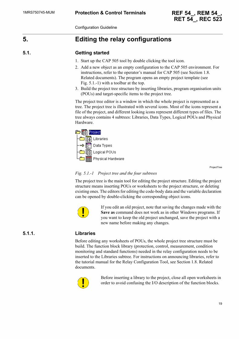
3. Build the project tree structure by inserting libraries, program organisation units (POUs) and target-specific items to the project tree.
The project tree editor is a window in which the whole project is represented as a tree. The project tree is illustrated with several icons. Most of the icons represent a file of the project, and different looking icons represent different types of files. The tree always contains 4 subtrees: Libraries, Data Types, Logical POUs and Physical Hardware.
ProjectTree
Fig. 5.1.-1 Project tree and the four subtrees
The project tree is the main tool for editing the project structure. Editing the project structure means inserting POUs or worksheets to the project structure, or deleting existing ones. The editors for editing the code-body data and the variable declaration can be opened by double-clicking the corresponding object icons.
5.1.1. LibrariesBefore editing any worksheets of POUs, the whole project tree structure must be build. The function block library (protection, control, measurement, condition monitoring and standard functions) needed in the relay configuration needs to be inserted to the Libraries subtree. For instructions on announcing libraries, refer to the tutorial manual for the Relay Configuration Tool, see Section 1.8. Related documents.
If you edit an old project, note that saving the changes made with the Save as command does not work as in other Windows programs. If you want to keep the old project unchanged, save the project with a new name before making any changes.
Before inserting a library to the project, close all open worksheets in order to avoid confusing the I/O description of the function blocks.
19
1MRS750745-MUMProtection & Control Terminals Configuration Guideline
REF 54_, REM 54_, RET 54_, REC 523
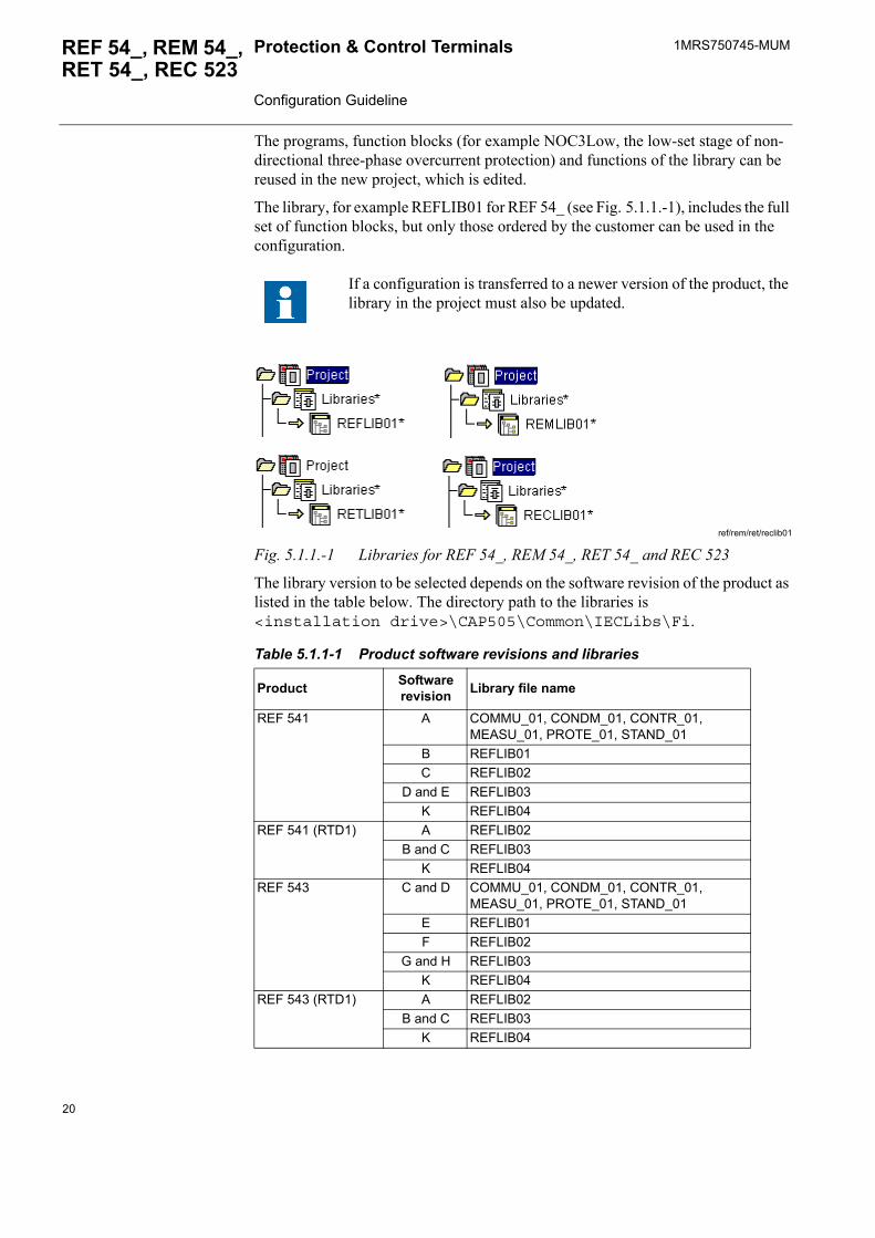
The programs, function blocks (for example NOC3Low, the low-set stage of non-directional three-phase overcurrent protection) and functions of the library can be reused in the new project, which is edited.
The library, for example REFLIB01 for REF 54_ (see Fig. 5.1.1.-1), includes the full set of function blocks, but only those ordered by the customer can be used in the configuration.
ref/rem/ret/reclib01
Fig. 5.1.1.-1 Libraries for REF 54_, REM 54_, RET 54_ and REC 523
The library version to be selected depends on the software revision of the product as listed in the table below. The directory path to the libraries is <installation drive>\CAP505\Common\IECLibs\Fi.
If a configuration is transferred to a newer version of the product, the library in the project must also be updated.
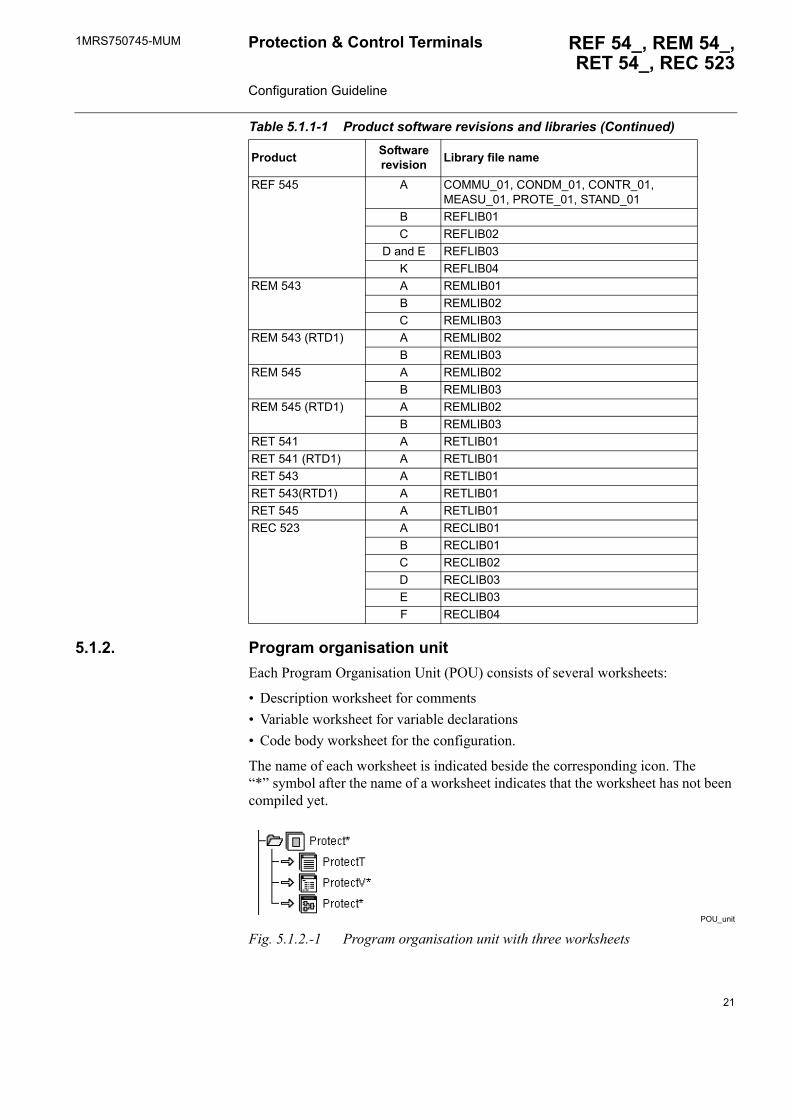
Table 5.1.1-1 Product software revisions and libraries
Product Software revision Library file name
REF 541 A COMMU_01, CONDM_01, CONTR_01, MEASU_01, PROTE_01, STAND_01
B REFLIB01C REFLIB02
D and E REFLIB03K REFLIB04
REF 541 (RTD1) A REFLIB02B and C REFLIB03
K REFLIB04REF 543 C and D COMMU_01, CONDM_01, CONTR_01,
MEASU_01, PROTE_01, STAND_01E REFLIB01F REFLIB02
G and H REFLIB03K REFLIB04
REF 543 (RTD1) A REFLIB02B and C REFLIB03
K REFLIB04
20
1MRS750745-MUM REF 54_, REM 54_,RET 54_, REC 523
Protection & Control Terminals Configuration Guideline
5.1.2. Program organisation unitEach Program Organisation Unit (POU) consists of several worksheets:
� Description worksheet for comments � Variable worksheet for variable declarations � Code body worksheet for the configuration.
The name of each worksheet is indicated beside the corresponding icon. The �*� symbol after the name of a worksheet indicates that the worksheet has not been compiled yet.
POU_unit
Fig. 5.1.2.-1 Program organisation unit with three worksheets
REF 545 A COMMU_01, CONDM_01, CONTR_01, MEASU_01, PROTE_01, STAND_01
B REFLIB01C REFLIB02
D and E REFLIB03K REFLIB04
REM 543 A REMLIB01B REMLIB02C REMLIB03
REM 543 (RTD1) A REMLIB02B REMLIB03
REM 545 A REMLIB02B REMLIB03
REM 545 (RTD1) A REMLIB02B REMLIB03
RET 541 A RETLIB01RET 541 (RTD1) A RETLIB01RET 543 A RETLIB01RET 543(RTD1) A RETLIB01RET 545 A RETLIB01REC 523 A RECLIB01
B RECLIB01C RECLIB02D RECLIB03E RECLIB03F RECLIB04
Table 5.1.1-1 Product software revisions and libraries (Continued)
Product Software revision Library file name
21
1MRS750745-MUMProtection & Control Terminals Configuration Guideline
REF 54_, REM 54_, RET 54_, REC 523
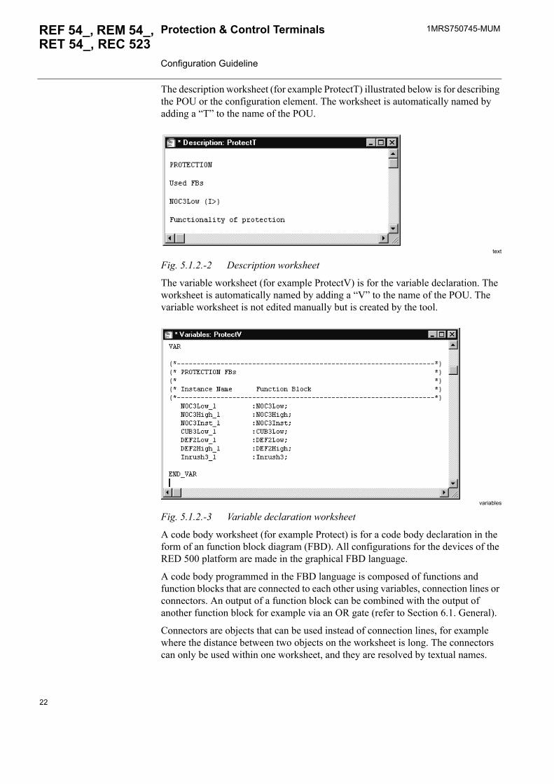
The description worksheet (for example ProtectT) illustrated below is for describing the POU or the configuration element. The worksheet is automatically named by adding a �T� to the name of the POU.
text
Fig. 5.1.2.-2 Description worksheet
The variable worksheet (for example ProtectV) is for the variable declaration. The worksheet is automatically named by adding a �V� to the name of the POU. The variable worksheet is not edited manually but is created by the tool.
variables
Fig. 5.1.2.-3 Variable declaration worksheet
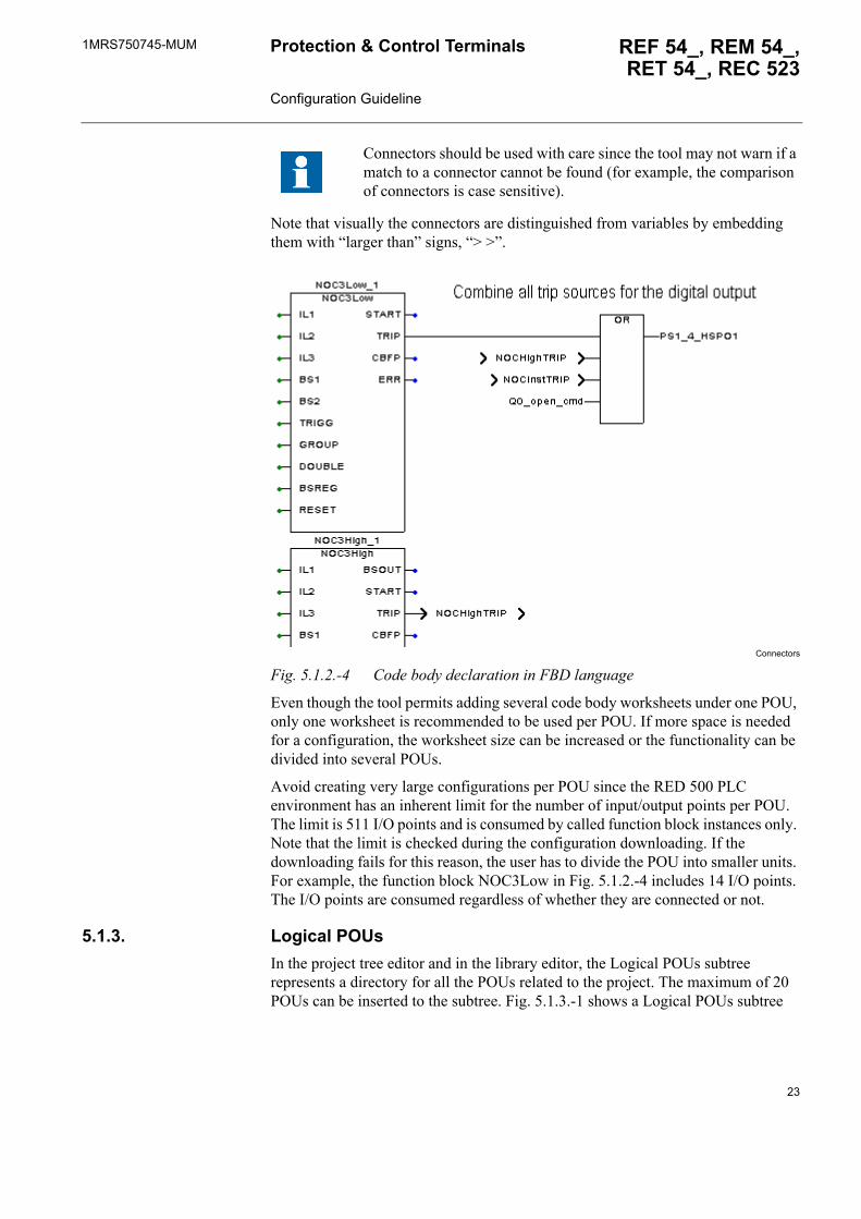
A code body worksheet (for example Protect) is for a code body declaration in the form of an function block diagram (FBD). All configurations for the devices of the RED 500 platform are made in the graphical FBD language.
A code body programmed in the FBD language is composed of functions and function blocks that are connected to each other using variables, connection lines or connectors. An output of a function block can be combined with the output of another function block for example via an OR gate (refer to Section 6.1. General).
Connectors are objects that can be used instead of connection lines, for example where the distance between two objects on the worksheet is long. The connectors can only be used within one worksheet, and they are resolved by textual names.
22
1MRS750745-MUM REF 54_, REM 54_,RET 54_, REC 523
Protection & Control Terminals Configuration Guideline
Note that visually the connectors are distinguished from variables by embedding them with �larger than� signs, �> >�.
Connectors
Fig. 5.1.2.-4 Code body declaration in FBD language
Even though the tool permits adding several code body worksheets under one POU, only one worksheet is recommended to be used per POU. If more space is needed for a configuration, the worksheet size can be increased or the functionality can be divided into several POUs.
Avoid creating very large configurations per POU since the RED 500 PLC environment has an inherent limit for the number of input/output points per POU. The limit is 511 I/O points and is consumed by called function block instances only. Note that the limit is checked during the configuration downloading. If the downloading fails for this reason, the user has to divide the POU into smaller units. For example, the function block NOC3Low in Fig. 5.1.2.-4 includes 14 I/O points. The I/O points are consumed regardless of whether they are connected or not.
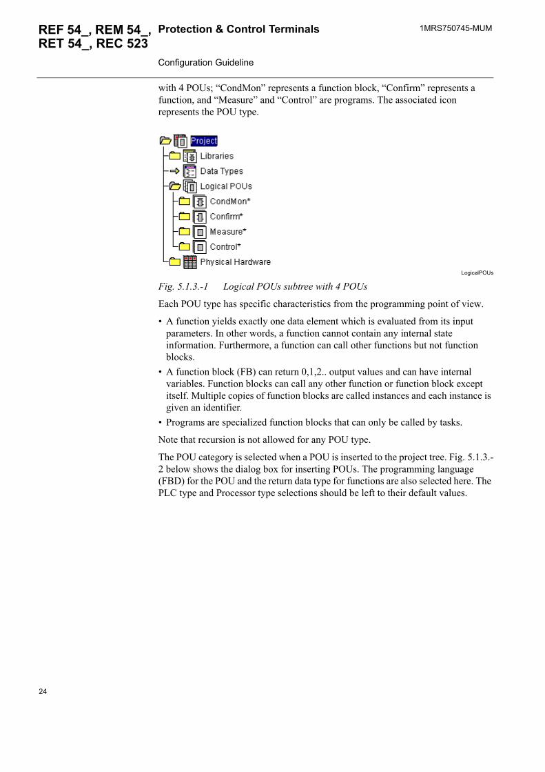
5.1.3. Logical POUsIn the project tree editor and in the library editor, the Logical POUs subtree represents a directory for all the POUs related to the project. The maximum of 20 POUs can be inserted to the subtree. Fig. 5.1.3.-1 shows a Logical POUs subtree
Connectors should be used with care since the tool may not warn if a match to a connector cannot be found (for example, the comparison of connectors is case sensitive).
23
1MRS750745-MUMProtection & Control Terminals Configuration Guideline
REF 54_, REM 54_, RET 54_, REC 523
with 4 POUs; �CondMon� represents a function block, �Confirm� represents a function, and �Measure� and �Control� are programs. The associated icon represents the POU type.
LogicalPOUs
Fig. 5.1.3.-1 Logical POUs subtree with 4 POUs
Each POU type has specific characteristics from the programming point of view.
� A function yields exactly one data element which is evaluated from its input parameters. In other words, a function cannot contain any internal state information. Furthermore, a function can call other functions but not function blocks.
� A function block (FB) can return 0,1,2.. output values and can have internal variables. Function blocks can call any other function or function block except itself. Multiple copies of function blocks are called instances and each instance is given an identifier.
� Programs are specialized function blocks that can only be called by tasks.
Note that recursion is not allowed for any POU type.
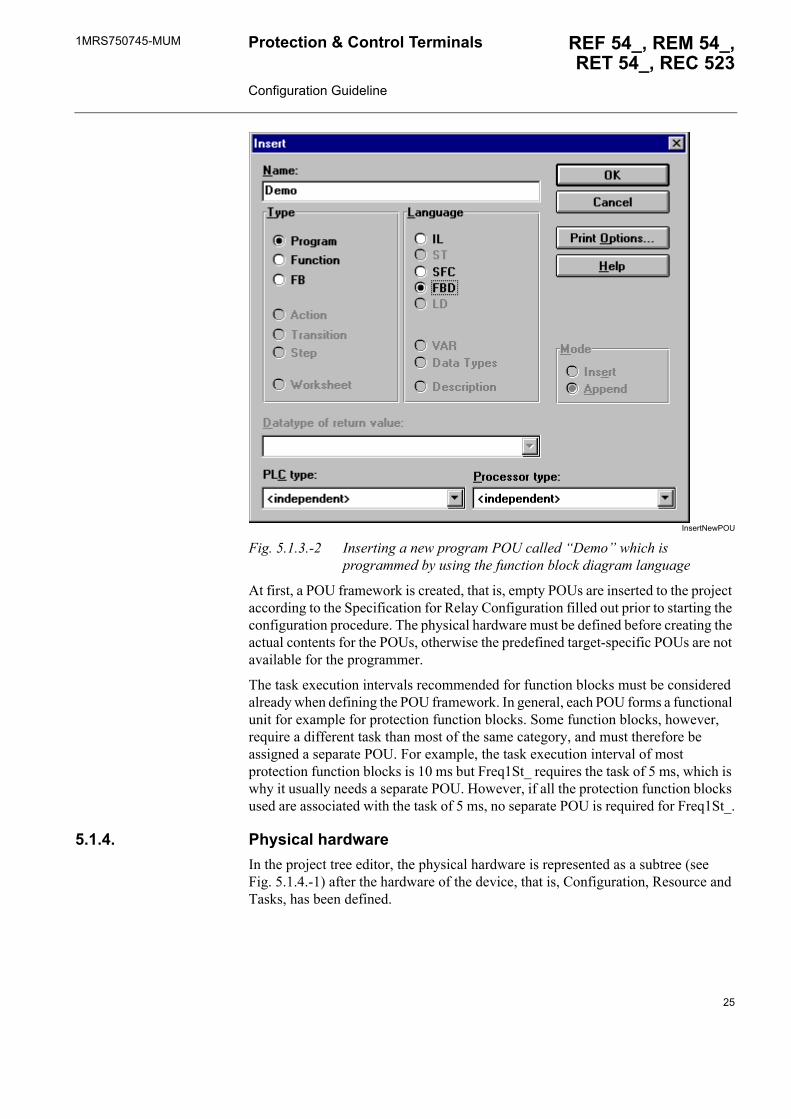
The POU category is selected when a POU is inserted to the project tree. Fig. 5.1.3.-2 below shows the dialog box for inserting POUs. The programming language (FBD) for the POU and the return data type for functions are also selected here. The PLC type and Processor type selections should be left to their default values.
24
1MRS750745-MUM REF 54_, REM 54_,RET 54_, REC 523
Protection & Control Terminals Configuration Guideline
InsertNewPOU
Fig. 5.1.3.-2 Inserting a new program POU called �Demo� which is programmed by using the function block diagram language
At first, a POU framework is created, that is, empty POUs are inserted to the project according to the Specification for Relay Configuration filled out prior to starting the configuration procedure. The physical hardware must be defined before creating the actual contents for the POUs, otherwise the predefined target-specific POUs are not available for the programmer.
The task execution intervals recommended for function blocks must be considered already when defining the POU framework. In general, each POU forms a functional unit for example for protection function blocks. Some function blocks, however, require a different task than most of the same category, and must therefore be assigned a separate POU. For example, the task execution interval of most protection function blocks is 10 ms but Freq1St_ requires the task of 5 ms, which is why it usually needs a separate POU. However, if all the protection function blocks used are associated with the task of 5 ms, no separate POU is required for Freq1St_.
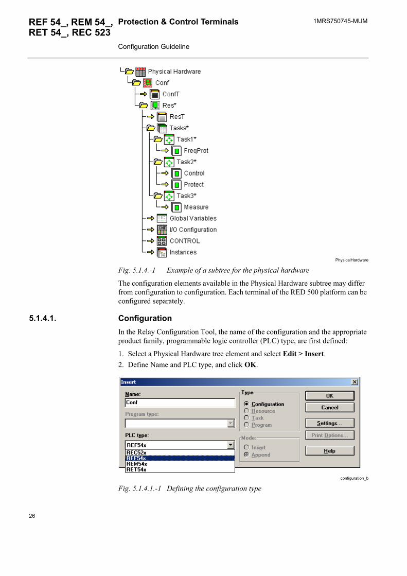
5.1.4. Physical hardwareIn the project tree editor, the physical hardware is represented as a subtree (see Fig. 5.1.4.-1) after the hardware of the device, that is, Configuration, Resource and Tasks, has been defined.
25
1MRS750745-MUMProtection & Control Terminals Configuration Guideline
REF 54_, REM 54_, RET 54_, REC 523
PhysicalHardware
Fig. 5.1.4.-1 Example of a subtree for the physical hardware
The configuration elements available in the Physical Hardware subtree may differ from configuration to configuration. Each terminal of the RED 500 platform can be configured separately.
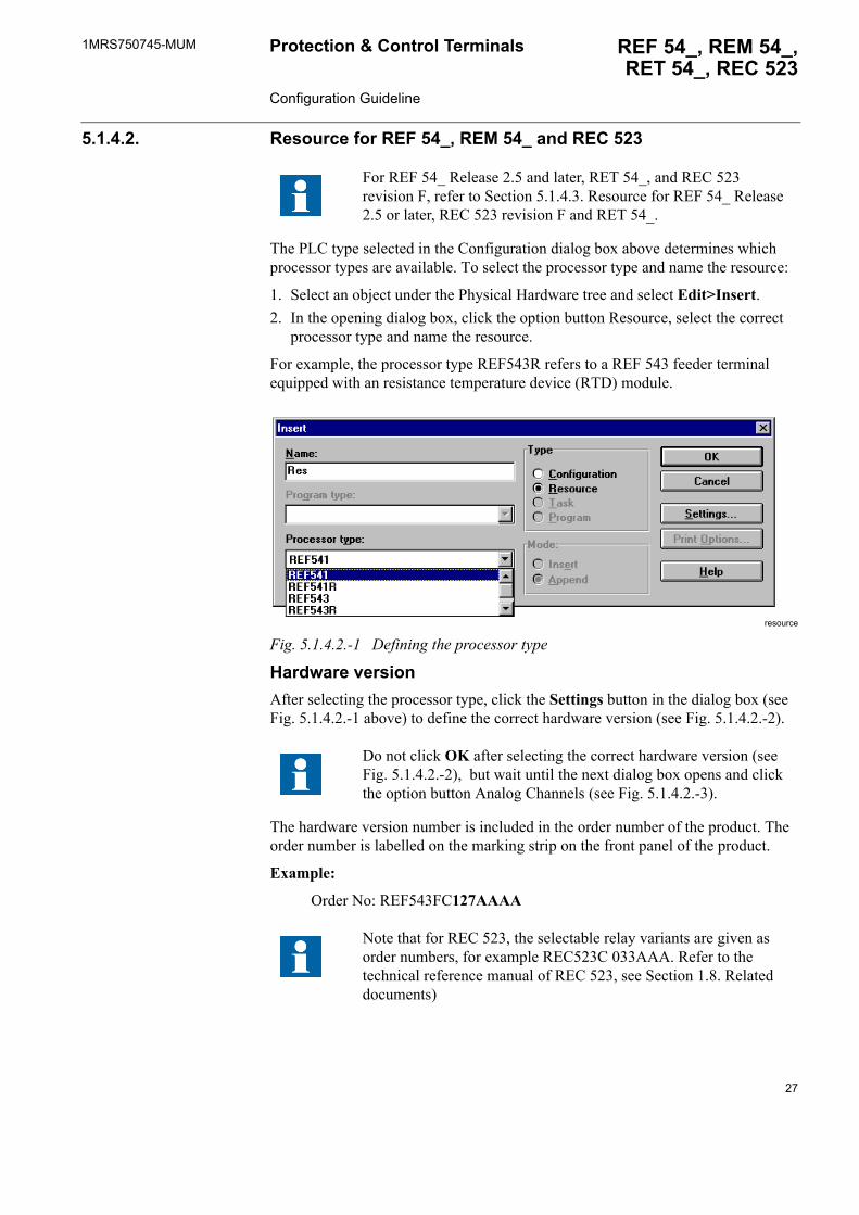
5.1.4.1. ConfigurationIn the Relay Configuration Tool, the name of the configuration and the appropriate product family, programmable logic controller (PLC) type, are first defined:
1. Select a Physical Hardware tree element and select Edit > Insert. 2. Define Name and PLC type, and click OK.
configuration_b
Fig. 5.1.4.1.-1 Defining the configuration type
26
1MRS750745-MUM REF 54_, REM 54_,RET 54_, REC 523
Protection & Control Terminals Configuration Guideline
5.1.4.2. Resource for REF 54_, REM 54_ and REC 523
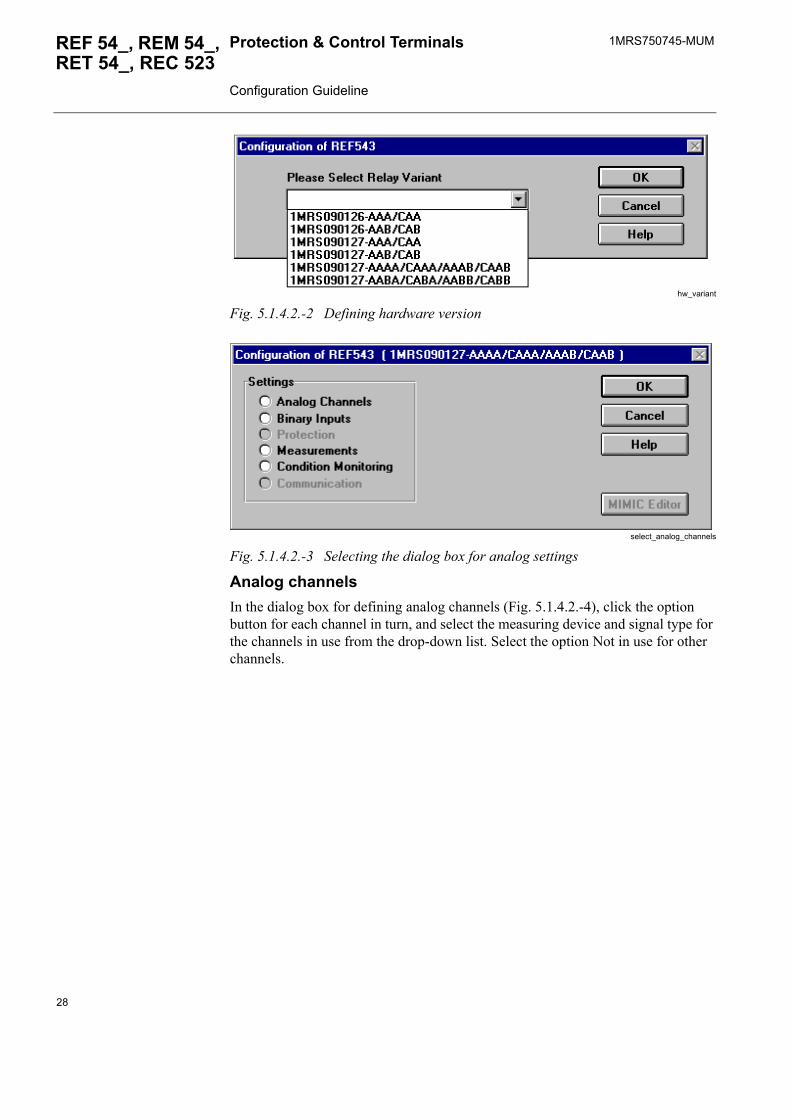
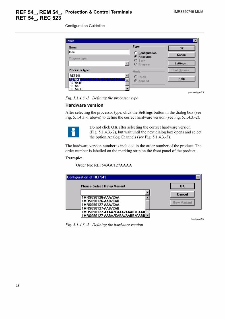
The PLC type selected in the Configuration dialog box above determines which processor types are available. To select the processor type and name the resource:
1. Select an object under the Physical Hardware tree and select Edit>Insert.2. In the opening dialog box, click the option button Resource, select the correct
processor type and name the resource.
For example, the processor type REF543R refers to a REF 543 feeder terminal equipped with an resistance temperature device (RTD) module.
resource
Fig. 5.1.4.2.-1 Defining the processor type
Hardware versionAfter selecting the processor type, click the Settings button in the dialog box (see Fig. 5.1.4.2.-1 above) to define the correct hardware version (see Fig. 5.1.4.2.-2).
The hardware version number is included in the order number of the product. The order number is labelled on the marking strip on the front panel of the product.
Example:
Order No: REF543FC127AAAA
For REF 54_ Release 2.5 and later, RET 54_, and REC 523 revision F, refer to Section 5.1.4.3. Resource for REF 54_ Release 2.5 or later, REC 523 revision F and RET 54_.
Do not click OK after selecting the correct hardware version (see Fig. 5.1.4.2.-2), but wait until the next dialog box opens and click the option button Analog Channels (see Fig. 5.1.4.2.-3).
Note that for REC 523, the selectable relay variants are given as order numbers, for example REC523C 033AAA. Refer to the technical reference manual of REC 523, see Section 1.8. Related documents)
27
1MRS750745-MUMProtection & Control Terminals Configuration Guideline
REF 54_, REM 54_, RET 54_, REC 523
hw_variant
Fig. 5.1.4.2.-2 Defining hardware version
select_analog_channels
Fig. 5.1.4.2.-3 Selecting the dialog box for analog settings
Analog channelsIn the dialog box for defining analog channels (Fig. 5.1.4.2.-4), click the option button for each channel in turn, and select the measuring device and signal type for the channels in use from the drop-down list. Select the option Not in use for other channels.
28
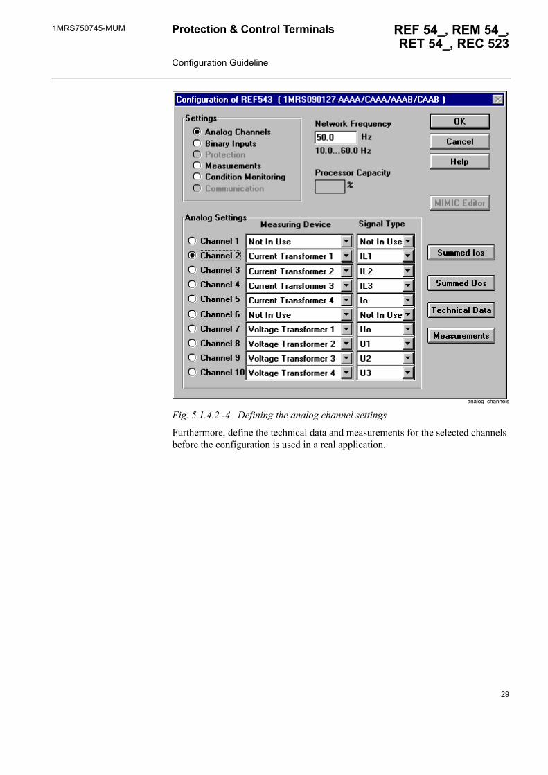
1MRS750745-MUM REF 54_, REM 54_,RET 54_, REC 523
Protection & Control Terminals Configuration Guideline
analog_channels
Fig. 5.1.4.2.-4 Defining the analog channel settings
Furthermore, define the technical data and measurements for the selected channels before the configuration is used in a real application.
29
1MRS750745-MUMProtection & Control Terminals Configuration Guideline
REF 54_, REM 54_, RET 54_, REC 523
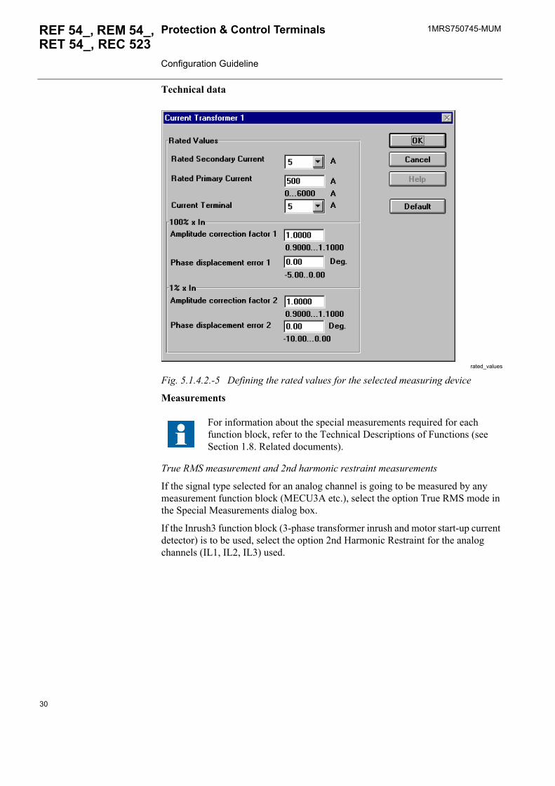
Technical data
rated_values
Fig. 5.1.4.2.-5 Defining the rated values for the selected measuring device
Measurements
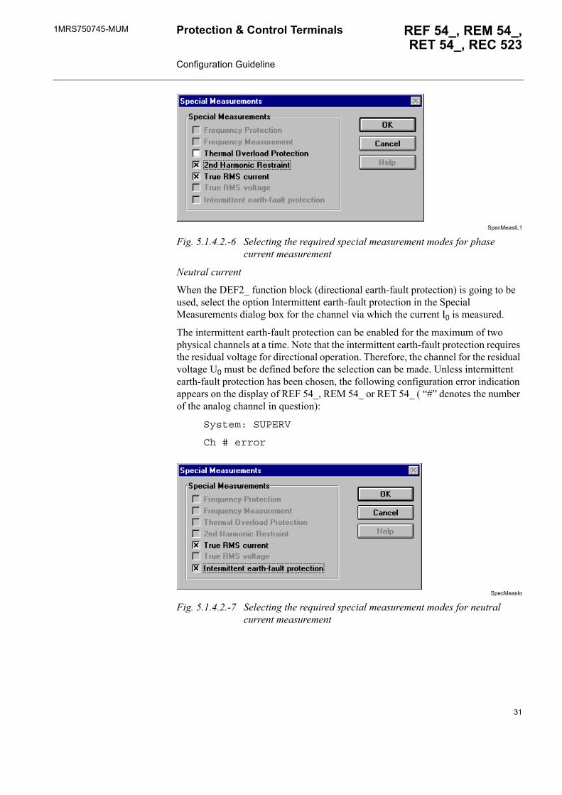
True RMS measurement and 2nd harmonic restraint measurements
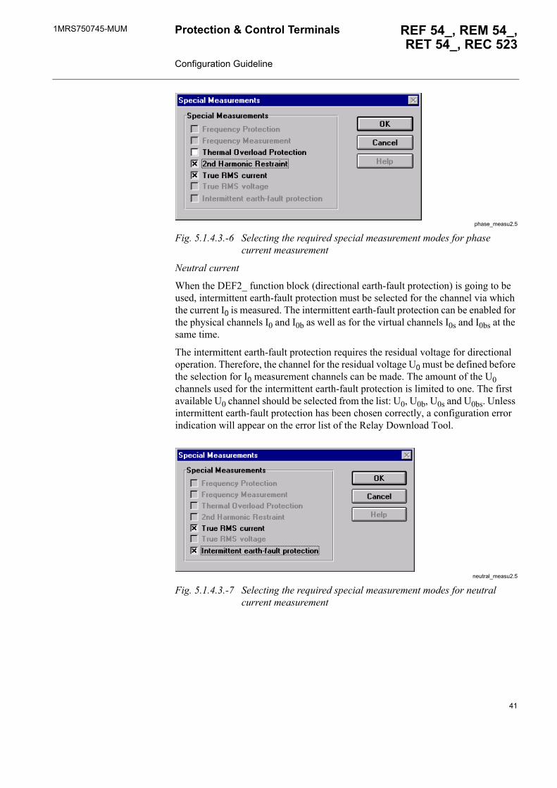
If the signal type selected for an analog channel is going to be measured by any measurement function block (MECU3A etc.), select the option True RMS mode in the Special Measurements dialog box.
If the Inrush3 function block (3-phase transformer inrush and motor start-up current detector) is to be used, select the option 2nd Harmonic Restraint for the analog channels (IL1, IL2, IL3) used.
For information about the special measurements required for each function block, refer to the Technical Descriptions of Functions (see Section 1.8. Related documents).
30
1MRS750745-MUM REF 54_, REM 54_,RET 54_, REC 523
Protection & Control Terminals Configuration Guideline
SpecMeasIL1
Fig. 5.1.4.2.-6 Selecting the required special measurement modes for phase current measurement
Neutral current
When the DEF2_ function block (directional earth-fault protection) is going to be used, select the option Intermittent earth-fault protection in the Special Measurements dialog box for the channel via which the current I0 is measured.
The intermittent earth-fault protection can be enabled for the maximum of two physical channels at a time. Note that the intermittent earth-fault protection requires the residual voltage for directional operation. Therefore, the channel for the residual voltage U0 must be defined before the selection can be made. Unless intermittent earth-fault protection has been chosen, the following configuration error indication appears on the display of REF 54_, REM 54_ or RET 54_ ( �#� denotes the number of the analog channel in question):
System: SUPERV
Ch # error
SpecMeasIo
Fig. 5.1.4.2.-7 Selecting the required special measurement modes for neutral current measurement
31
1MRS750745-MUMProtection & Control Terminals Configuration Guideline
REF 54_, REM 54_, RET 54_, REC 523
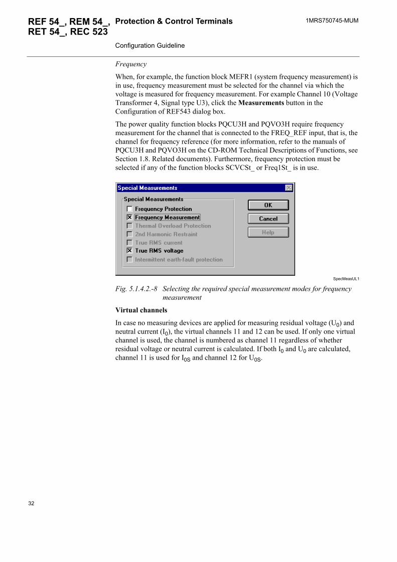
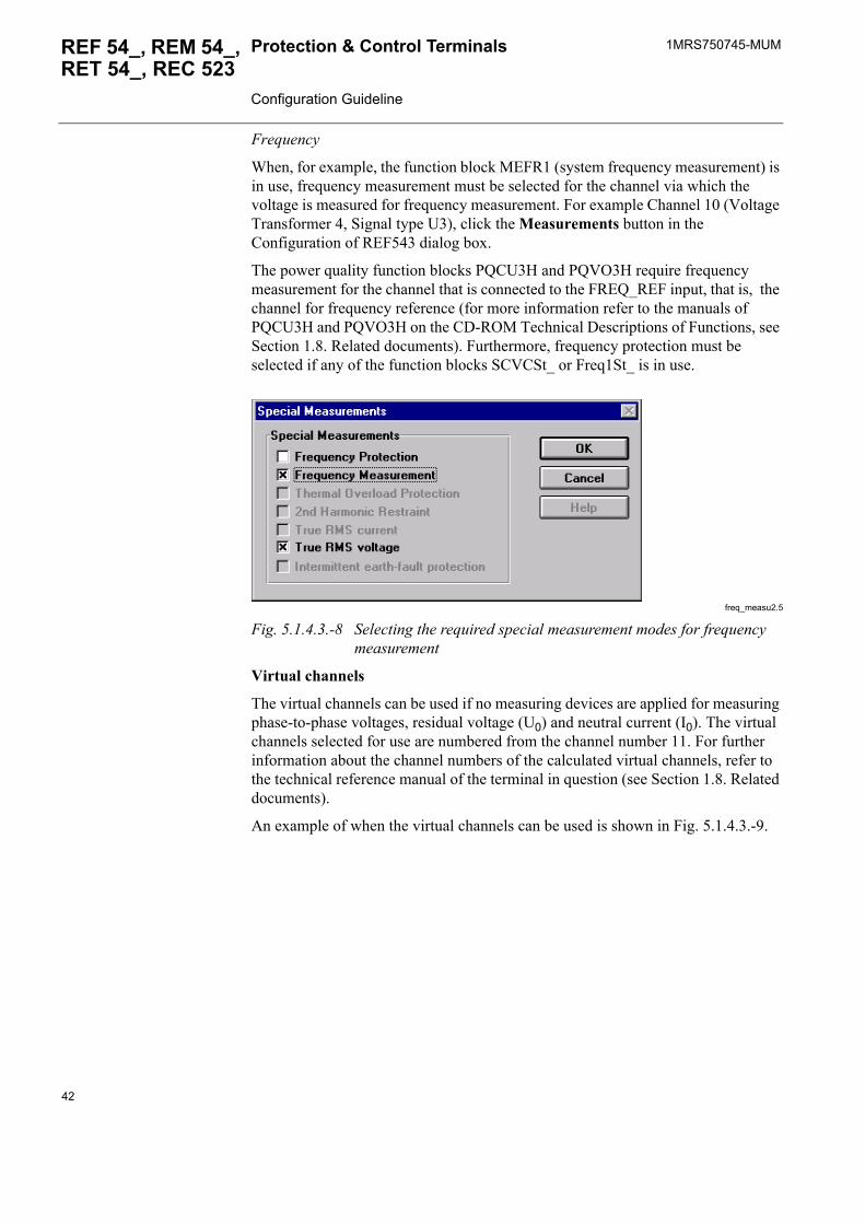
Frequency
When, for example, the function block MEFR1 (system frequency measurement) is in use, frequency measurement must be selected for the channel via which the voltage is measured for frequency measurement. For example Channel 10 (Voltage Transformer 4, Signal type U3), click the Measurements button in the Configuration of REF543 dialog box.
The power quality function blocks PQCU3H and PQVO3H require frequency measurement for the channel that is connected to the FREQ_REF input, that is, the channel for frequency reference (for more information, refer to the manuals of PQCU3H and PQVO3H on the CD-ROM Technical Descriptions of Functions, see Section 1.8. Related documents). Furthermore, frequency protection must be selected if any of the function blocks SCVCSt_ or Freq1St_ is in use.
SpecMeasUL1
Fig. 5.1.4.2.-8 Selecting the required special measurement modes for frequency measurement
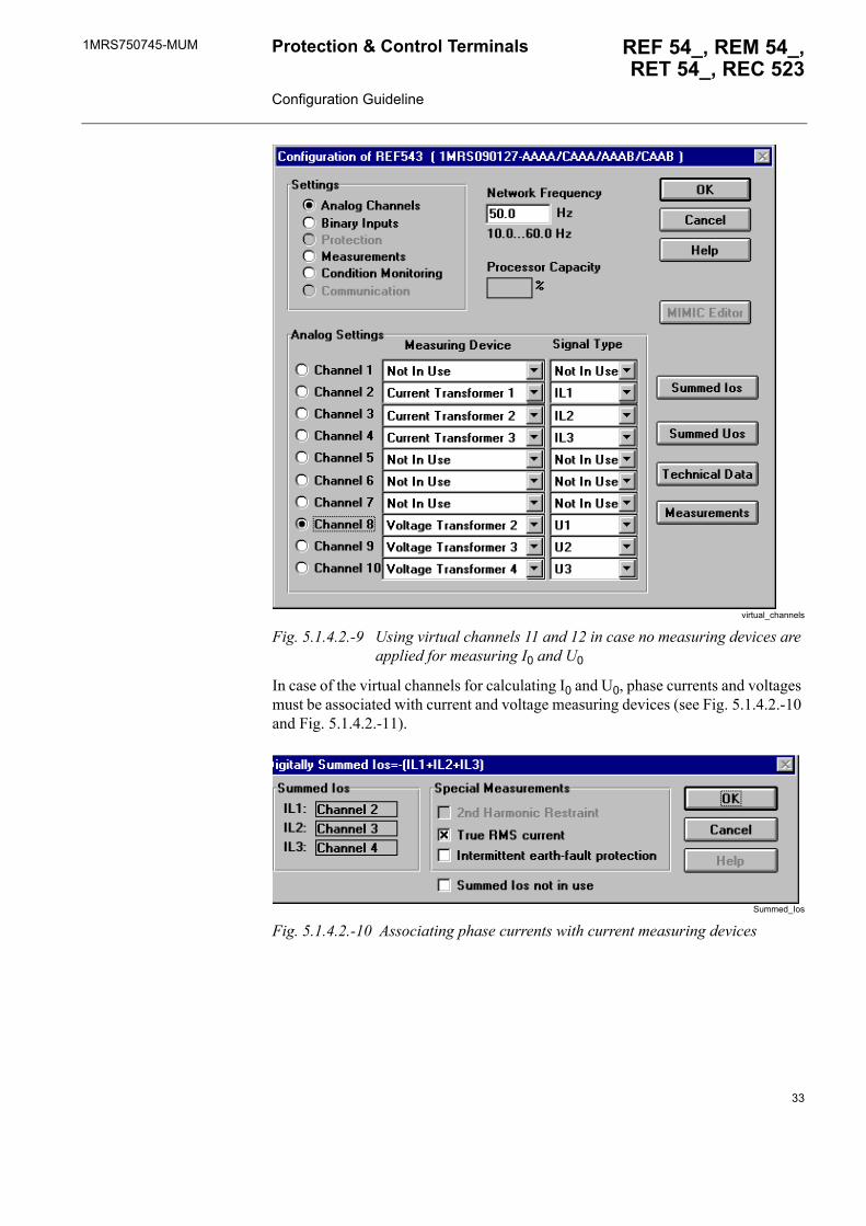
Virtual channels
In case no measuring devices are applied for measuring residual voltage (U0) and neutral current (I0), the virtual channels 11 and 12 can be used. If only one virtual channel is used, the channel is numbered as channel 11 regardless of whether residual voltage or neutral current is calculated. If both I0 and U0 are calculated, channel 11 is used for I0S and channel 12 for U0S.
32
1MRS750745-MUM REF 54_, REM 54_,RET 54_, REC 523
Protection & Control Terminals Configuration Guideline
virtual_channels
Fig. 5.1.4.2.-9 Using virtual channels 11 and 12 in case no measuring devices are applied for measuring I0 and U0
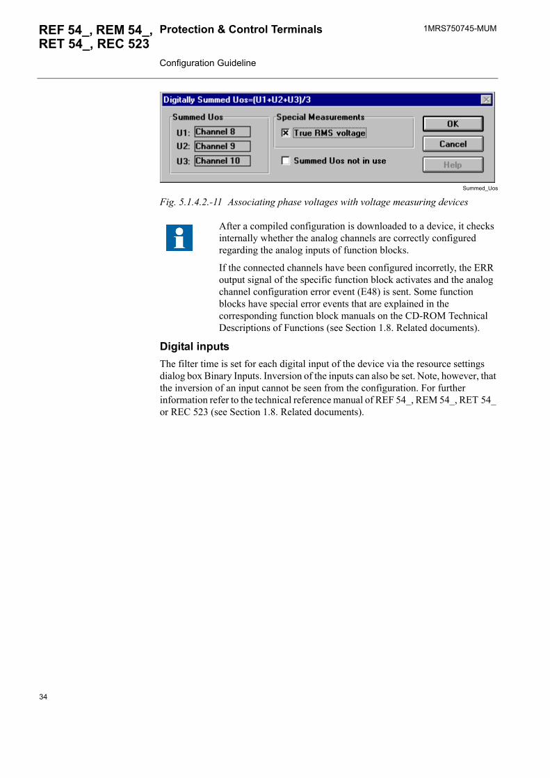
In case of the virtual channels for calculating I0 and U0, phase currents and voltages must be associated with current and voltage measuring devices (see Fig. 5.1.4.2.-10 and Fig. 5.1.4.2.-11).
Summed_Ios
Fig. 5.1.4.2.-10 Associating phase currents with current measuring devices
33
1MRS750745-MUMProtection & Control Terminals Configuration Guideline
REF 54_, REM 54_, RET 54_, REC 523
Summed_Uos
Fig. 5.1.4.2.-11 Associating phase voltages with voltage measuring devices
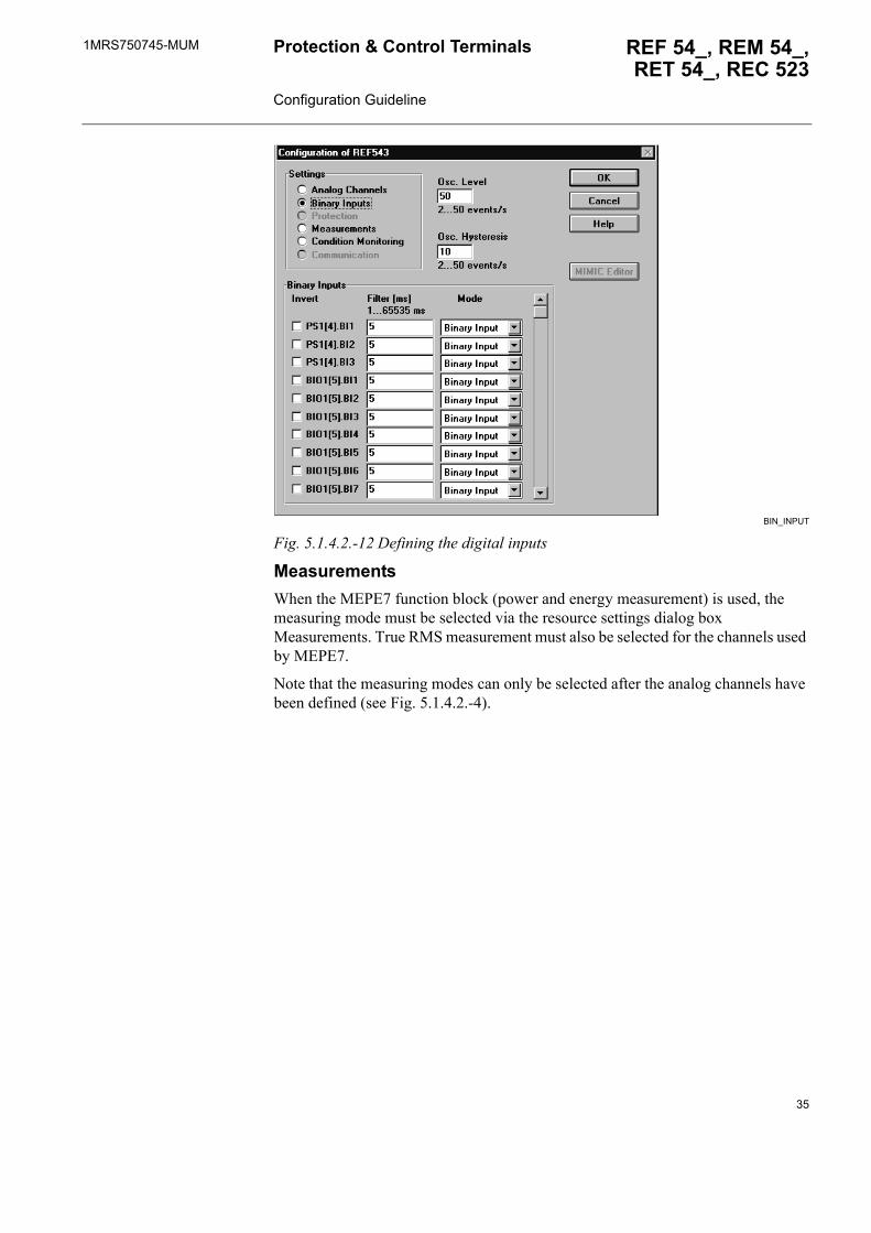
Digital inputsThe filter time is set for each digital input of the device via the resource settings dialog box Binary Inputs. Inversion of the inputs can also be set. Note, however, that the inversion of an input cannot be seen from the configuration. For further information refer to the technical reference manual of REF 54_, REM 54_, RET 54_ or REC 523 (see Section 1.8. Related documents).
After a compiled configuration is downloaded to a device, it checks internally whether the analog channels are correctly configured regarding the analog inputs of function blocks.
If the connected channels have been configured incorretly, the ERR output signal of the specific function block activates and the analog channel configuration error event (E48) is sent. Some function blocks have special error events that are explained in the corresponding function block manuals on the CD-ROM Technical Descriptions of Functions (see Section 1.8. Related documents).
34
1MRS750745-MUM REF 54_, REM 54_,RET 54_, REC 523
Protection & Control Terminals Configuration Guideline
BIN_INPUT
Fig. 5.1.4.2.-12 Defining the digital inputs
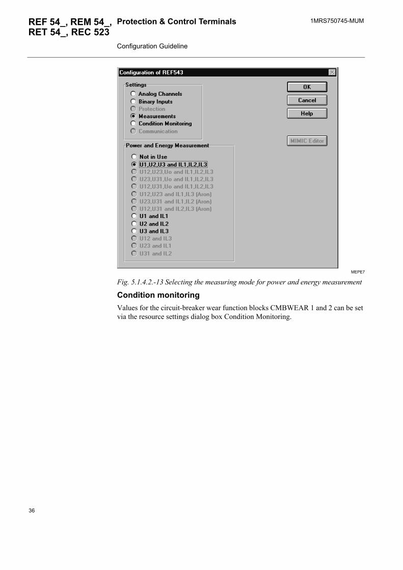
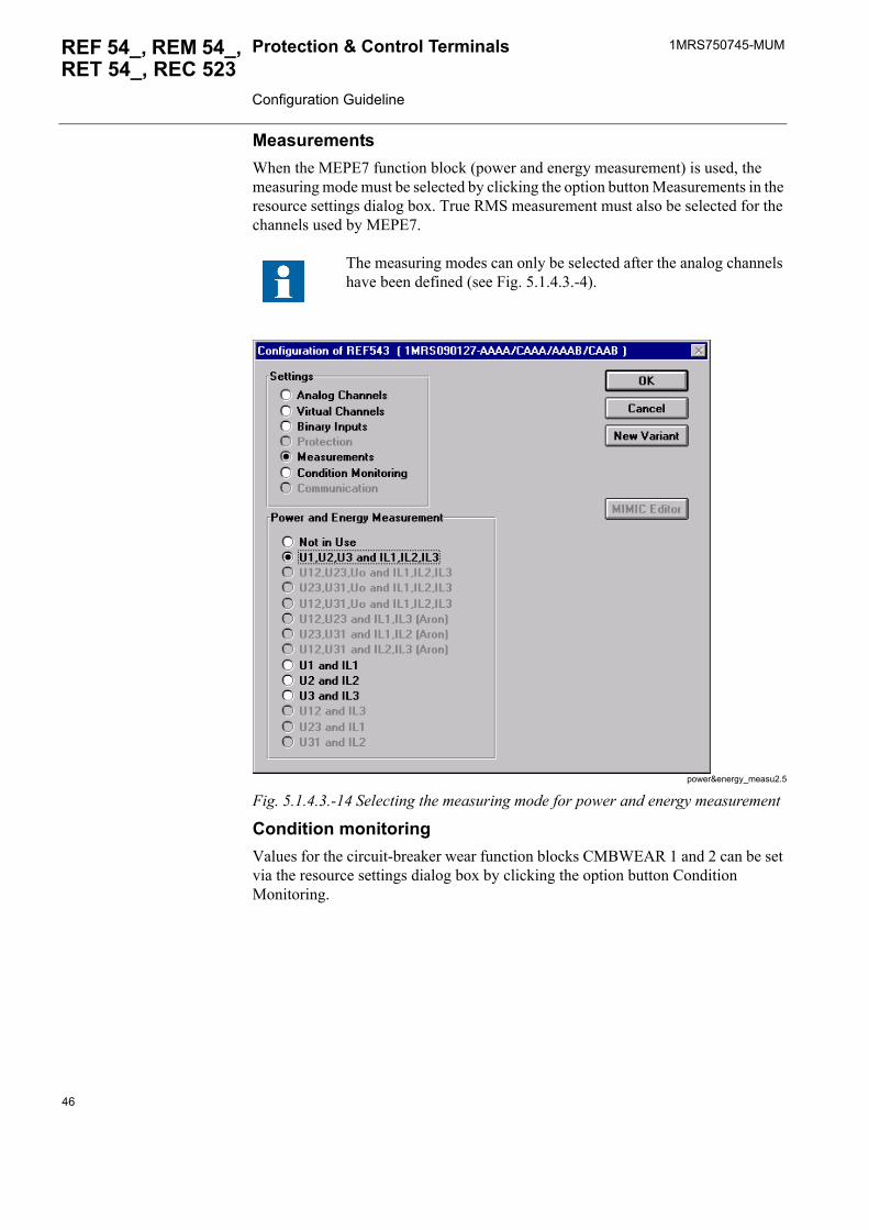
MeasurementsWhen the MEPE7 function block (power and energy measurement) is used, the measuring mode must be selected via the resource settings dialog box Measurements. True RMS measurement must also be selected for the channels used by MEPE7.
Note that the measuring modes can only be selected after the analog channels have been defined (see Fig. 5.1.4.2.-4).
35
1MRS750745-MUMProtection & Control Terminals Configuration Guideline
REF 54_, REM 54_, RET 54_, REC 523
MEPE7
Fig. 5.1.4.2.-13 Selecting the measuring mode for power and energy measurement
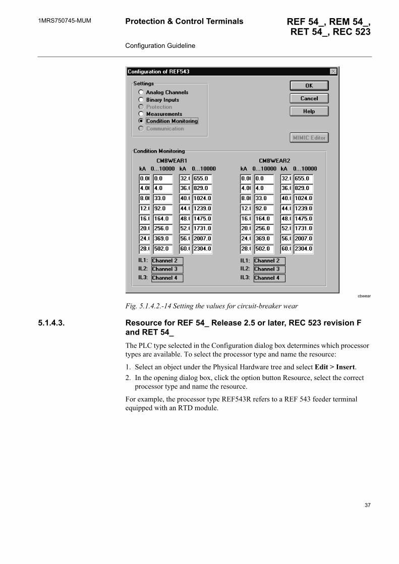
Condition monitoringValues for the circuit-breaker wear function blocks CMBWEAR 1 and 2 can be set via the resource settings dialog box Condition Monitoring.
36
1MRS750745-MUM REF 54_, REM 54_,RET 54_, REC 523
Protection & Control Terminals Configuration Guideline
cbwear
Fig. 5.1.4.2.-14 Setting the values for circuit-breaker wear
5.1.4.3. Resource for REF 54_ Release 2.5 or later, REC 523 revision F and RET 54_The PLC type selected in the Configuration dialog box determines which processor types are available. To select the processor type and name the resource:
1. Select an object under the Physical Hardware tree and select Edit > Insert.2. In the opening dialog box, click the option button Resource, select the correct
processor type and name the resource.
For example, the processor type REF543R refers to a REF 543 feeder terminal equipped with an RTD module.
37
1MRS750745-MUMProtection & Control Terminals Configuration Guideline
REF 54_, REM 54_, RET 54_, REC 523
processtype2.5
Fig. 5.1.4.3.-1 Defining the processor type
Hardware versionAfter selecting the processor type, click the Settings button in the dialog box (see Fig. 5.1.4.3.-1 above) to define the correct hardware version (see Fig. 5.1.4.3.-2).
The hardware version number is included in the order number of the product. The order number is labelled on the marking strip on the front panel of the product.
Example:
Order No: REF543GC127AAAA
hardware2.5
Fig. 5.1.4.3.-2 Defining the hardware version
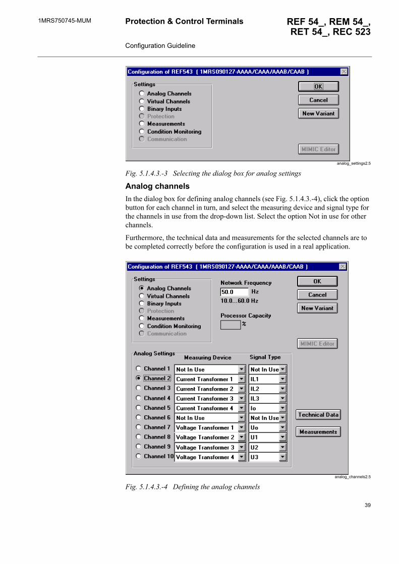
Do not click OK after selecting the correct hardware version (Fig. 5.1.4.3.-2), but wait until the next dialog box opens and select the option Analog Channels (see Fig. 5.1.4.3.-3).
38
1MRS750745-MUM REF 54_, REM 54_,RET 54_, REC 523
Protection & Control Terminals Configuration Guideline
analog_settings2.5
Fig. 5.1.4.3.-3 Selecting the dialog box for analog settings
Analog channelsIn the dialog box for defining analog channels (see Fig. 5.1.4.3.-4), click the option button for each channel in turn, and select the measuring device and signal type for the channels in use from the drop-down list. Select the option Not in use for other channels.
Furthermore, the technical data and measurements for the selected channels are to be completed correctly before the configuration is used in a real application.
analog_channels2.5
Fig. 5.1.4.3.-4 Defining the analog channels
39

1MRS750745-MUMProtection & Control Terminals Configuration Guideline
REF 54_, REM 54_, RET 54_, REC 523
Technical data
rated_values2.5
Fig. 5.1.4.3.-5 Defining the rated values for the selected measuring device
Measurements
True RMS and 2nd harmonic restraint measurements
If the signal type selected for an analog channel is going to be measured by any measurement function block (MECU3A etc.), the true RMS mode must be selected in the Special Measurements dialog box. Moreover, in case the Inrush3 function block (3-phase transformer inrush and motor start-up current detector) is to be used, the 2nd harmonic restraint must be selected for the analog channels (IL1, IL2, IL3) used.
For information about the special measurements required for each function block, refer to the Technical Descriptions of Functions (see Section 1.8. Related documents).
40
1MRS750745-MUM REF 54_, REM 54_,RET 54_, REC 523
Protection & Control Terminals Configuration Guideline
phase_measu2.5
Fig. 5.1.4.3.-6 Selecting the required special measurement modes for phase current measurement
Neutral current
When the DEF2_ function block (directional earth-fault protection) is going to be used, intermittent earth-fault protection must be selected for the channel via which the current I0 is measured. The intermittent earth-fault protection can be enabled for the physical channels I0 and I0b as well as for the virtual channels I0s and I0bs at the same time.
The intermittent earth-fault protection requires the residual voltage for directional operation. Therefore, the channel for the residual voltage U0 must be defined before the selection for I0 measurement channels can be made. The amount of the U0 channels used for the intermittent earth-fault protection is limited to one. The first available U0 channel should be selected from the list: U0, U0b, U0s and U0bs. Unless intermittent earth-fault protection has been chosen correctly, a configuration error indication will appear on the error list of the Relay Download Tool.
neutral_measu2.5
Fig. 5.1.4.3.-7 Selecting the required special measurement modes for neutral current measurement
41
1MRS750745-MUMProtection & Control Terminals Configuration Guideline
REF 54_, REM 54_, RET 54_, REC 523
Frequency
When, for example, the function block MEFR1 (system frequency measurement) is in use, frequency measurement must be selected for the channel via which the voltage is measured for frequency measurement. For example Channel 10 (Voltage Transformer 4, Signal type U3), click the Measurements button in the Configuration of REF543 dialog box.
The power quality function blocks PQCU3H and PQVO3H require frequency measurement for the channel that is connected to the FREQ_REF input, that is, the channel for frequency reference (for more information refer to the manuals of PQCU3H and PQVO3H on the CD-ROM Technical Descriptions of Functions, see Section 1.8. Related documents). Furthermore, frequency protection must be selected if any of the function blocks SCVCSt_ or Freq1St_ is in use.
freq_measu2.5
Fig. 5.1.4.3.-8 Selecting the required special measurement modes for frequency measurement
Virtual channels
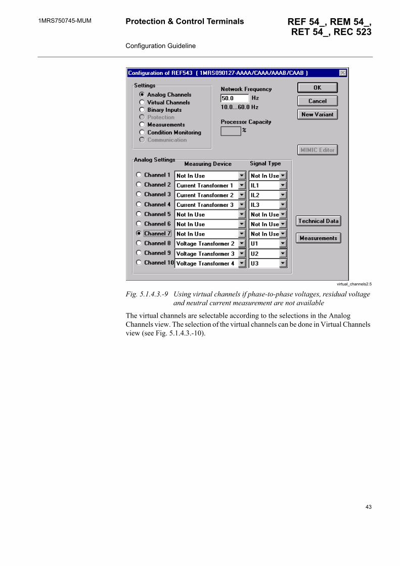
The virtual channels can be used if no measuring devices are applied for measuring phase-to-phase voltages, residual voltage (U0) and neutral current (I0). The virtual channels selected for use are numbered from the channel number 11. For further information about the channel numbers of the calculated virtual channels, refer to the technical reference manual of the terminal in question (see Section 1.8. Related documents).
An example of when the virtual channels can be used is shown in Fig. 5.1.4.3.-9.
42
1MRS750745-MUM REF 54_, REM 54_,RET 54_, REC 523
Protection & Control Terminals Configuration Guideline
virtual_channels2.5
Fig. 5.1.4.3.-9 Using virtual channels if phase-to-phase voltages, residual voltage and neutral current measurement are not available
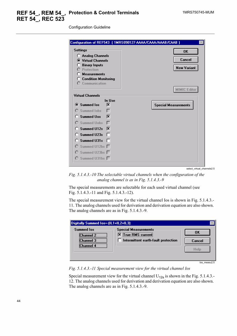
The virtual channels are selectable according to the selections in the Analog Channels view. The selection of the virtual channels can be done in Virtual Channels view (see Fig. 5.1.4.3.-10).
43
1MRS750745-MUMProtection & Control Terminals Configuration Guideline
REF 54_, REM 54_, RET 54_, REC 523
select_virtual_channels2.5
Fig. 5.1.4.3.-10 The selectable virtual channels when the configuration of the analog channel is as in Fig. 5.1.4.3.-9
The special measurements are selectable for each used virtual channel (see Fig. 5.1.4.3.-11 and Fig. 5.1.4.3.-12).
The special measurement view for the virtual channel Ios is shown in Fig. 5.1.4.3.-11. The analog channels used for derivation and derivation equation are also shown. The analog channels are as in Fig. 5.1.4.3.-9.
Ios_measu2.5
Fig. 5.1.4.3.-11 Special measurement view for the virtual channel Ios
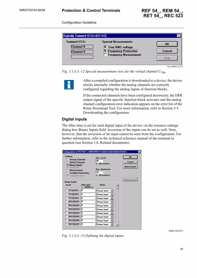
Special measurement view for the virtual channel U12s is shown in the Fig. 5.1.4.3.-12. The analog channels used for derivation and derivation equation are also shown. The analog channels are as in Fig. 5.1.4.3.-9.
44
1MRS750745-MUM REF 54_, REM 54_,RET 54_, REC 523
Protection & Control Terminals Configuration Guideline
Ios_measu_2.5_2
Fig. 5.1.4.3.-12 Special measurement view for the virtual channel U12s.
Digital inputsThe filter time is set for each digital input of the device via the resource settings dialog box Binary Inputs field. Inversion of the inputs can be set as well. Note, however, that the inversion of an input cannot be seen from the configuration. For further information, refer to the technical reference manual of the terminal in question (see Section 1.8. Related documents).
digital_inputs2.5
Fig. 5.1.4.3.-13 Defining the digital inputs
After a compiled configuration is downloaded to a device, the device checks internally whether the analog channels are correctly configured regarding the analog inputs of function blocks.
If the connected channels have been configured incorrectly, the ERR output signal of the specific function block activates and the analog channel configuration error indication appears on the error list of the Relay Download Tool. For more information, refer to Section 5.5. Downloading the configuration.
45
1MRS750745-MUMProtection & Control Terminals Configuration Guideline
REF 54_, REM 54_, RET 54_, REC 523
MeasurementsWhen the MEPE7 function block (power and energy measurement) is used, the measuring mode must be selected by clicking the option button Measurements in the resource settings dialog box. True RMS measurement must also be selected for the channels used by MEPE7.
power&energy_measu2.5
Fig. 5.1.4.3.-14 Selecting the measuring mode for power and energy measurement
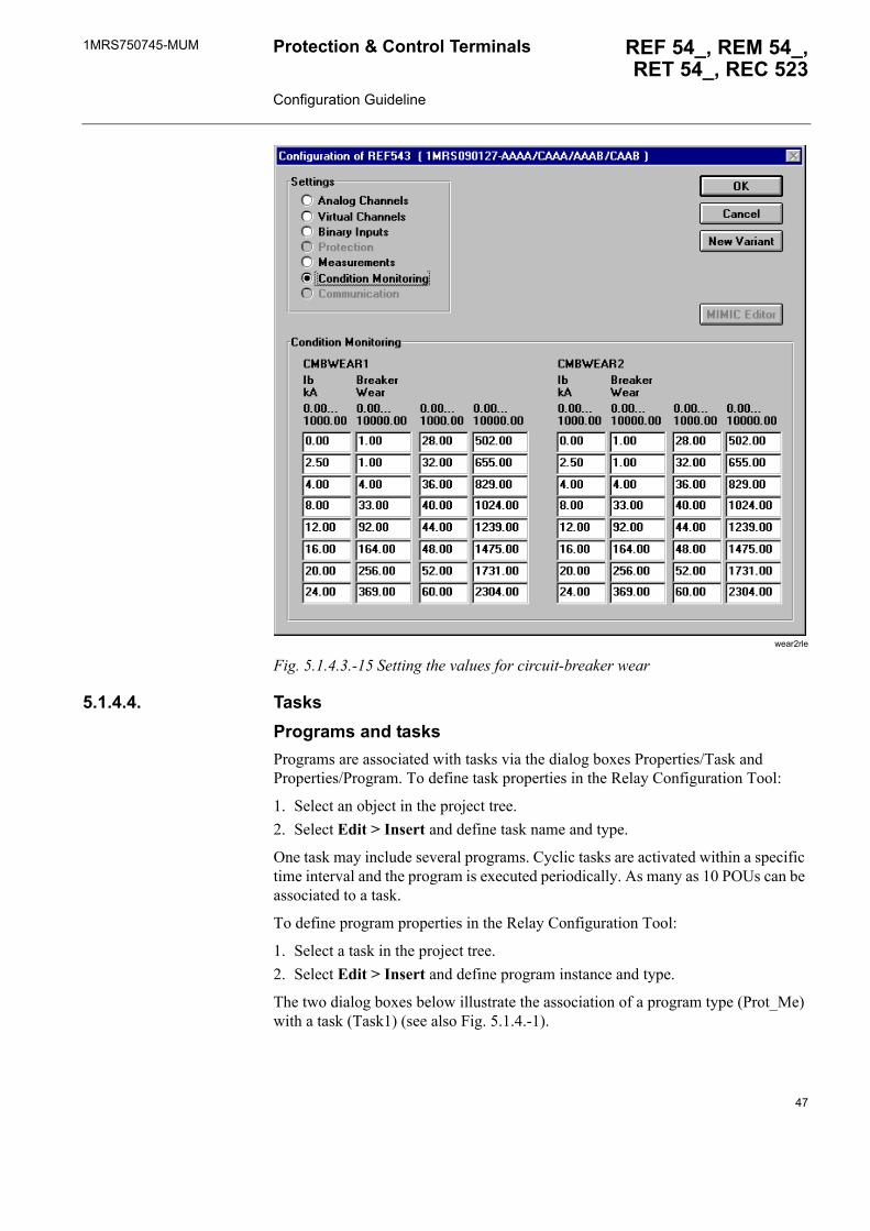
Condition monitoringValues for the circuit-breaker wear function blocks CMBWEAR 1 and 2 can be set via the resource settings dialog box by clicking the option button Condition Monitoring.
The measuring modes can only be selected after the analog channels have been defined (see Fig. 5.1.4.3.-4).
46
1MRS750745-MUM REF 54_, REM 54_,RET 54_, REC 523
Protection & Control Terminals Configuration Guideline
wear2rle
Fig. 5.1.4.3.-15 Setting the values for circuit-breaker wear
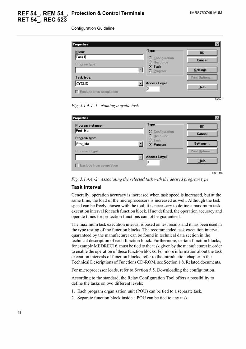
5.1.4.4. TasksPrograms and tasksPrograms are associated with tasks via the dialog boxes Properties/Task and Properties/Program. To define task properties in the Relay Configuration Tool:
1. Select an object in the project tree.2. Select Edit > Insert and define task name and type.
One task may include several programs. Cyclic tasks are activated within a specific time interval and the program is executed periodically. As many as 10 POUs can be associated to a task.
To define program properties in the Relay Configuration Tool:
1. Select a task in the project tree.2. Select Edit > Insert and define program instance and type.
The two dialog boxes below illustrate the association of a program type (Prot_Me) with a task (Task1) (see also Fig. 5.1.4.-1).
47
1MRS750745-MUMProtection & Control Terminals Configuration Guideline
REF 54_, REM 54_, RET 54_, REC 523
TASK1
Fig. 5.1.4.4.-1 Naming a cyclic task
PROT_ME
Fig. 5.1.4.4.-2 Associating the selected task with the desired program type
Task intervalGenerally, operation accuracy is increased when task speed is increased, but at the same time, the load of the microprocessors is increased as well. Although the task speed can be freely chosen with the tool, it is necessary to define a maximum task execution interval for each function block. If not defined, the operation accuracy and operate times for protection functions cannot be guaranteed.
The maximum task execution interval is based on test results and it has been used in the type testing of the function blocks. The recommended task execution interval quaranteed by the manufacturer can be found in technical data section in the technical description of each function block. Furthermore, certain function blocks, for example MEDREC16, must be tied to the task given by the manufacturer in order to enable the operation of these function blocks. For more information about the task execution intervals of function blocks, refer to the introduction chapter in the Technical Descriptions of Functions CD-ROM, see Section 1.8. Related documents.
For microprocessor loads, refer to Section 5.5. Downloading the configuration.
According to the standard, the Relay Configuration Tool offers a possibility to define the tasks on two different levels:
1. Each program organisation unit (POU) can be tied to a separate task.2. Separate function block inside a POU can be tied to any task.
48
1MRS750745-MUM REF 54_, REM 54_,RET 54_, REC 523
Protection & Control Terminals Configuration Guideline
However, the second alternative is not supported in the RED 500 environment; if a separate function block inside a POU is given a separate task definition, it is ignored when transferred to the device. This means that when the function blocks are being placed in different POUs, not only the category of the function (protection, control, and so on) but also the maximum task execution interval should be considered, since all function blocks inside a POU run at the same speed.
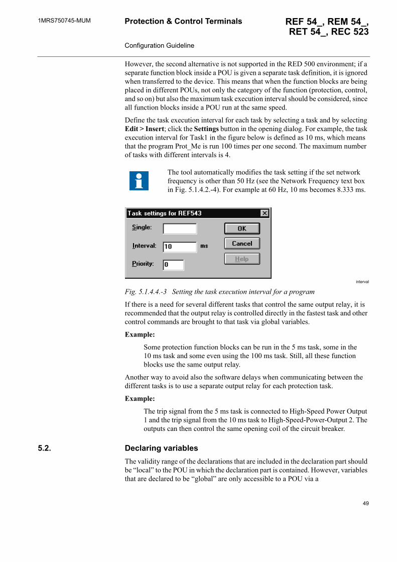
Define the task execution interval for each task by selecting a task and by selecting Edit > Insert; click the Settings button in the opening dialog. For example, the task execution interval for Task1 in the figure below is defined as 10 ms, which means that the program Prot_Me is run 100 times per one second. The maximum number of tasks with different intervals is 4.
interval
Fig. 5.1.4.4.-3 Setting the task execution interval for a program
If there is a need for several different tasks that control the same output relay, it is recommended that the output relay is controlled directly in the fastest task and other control commands are brought to that task via global variables.
Example:
Some protection function blocks can be run in the 5 ms task, some in the 10 ms task and some even using the 100 ms task. Still, all these function blocks use the same output relay.
Another way to avoid also the software delays when communicating between the different tasks is to use a separate output relay for each protection task.
Example:
The trip signal from the 5 ms task is connected to High-Speed Power Output 1 and the trip signal from the 10 ms task to High-Speed-Power-Output 2. The outputs can then control the same opening coil of the circuit breaker.
5.2. Declaring variablesThe validity range of the declarations that are included in the declaration part should be �local� to the POU in which the declaration part is contained. However, variables that are declared to be �global� are only accessible to a POU via a
The tool automatically modifies the task setting if the set network frequency is other than 50 Hz (see the Network Frequency text box in Fig. 5.1.4.2.-4). For example at 60 Hz, 10 ms becomes 8.333 ms.
49
1MRS750745-MUMProtection & Control Terminals Configuration Guideline
REF 54_, REM 54_, RET 54_, REC 523
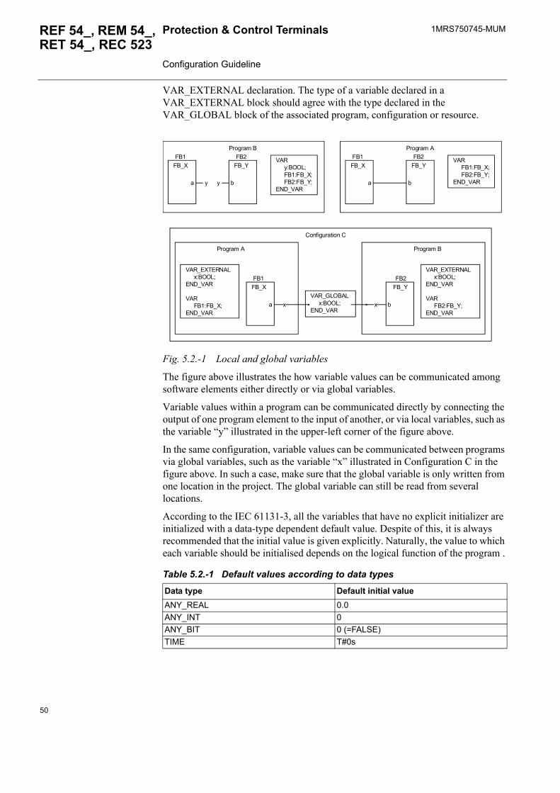
VAR_EXTERNAL declaration. The type of a variable declared in a VAR_EXTERNAL block should agree with the type declared in the VAR_GLOBAL block of the associated program, configuration or resource.
Fig. 5.2.-1 Local and global variables
The figure above illustrates the how variable values can be communicated among software elements either directly or via global variables.
Variable values within a program can be communicated directly by connecting the output of one program element to the input of another, or via local variables, such as the variable �y� illustrated in the upper-left corner of the figure above.
In the same configuration, variable values can be communicated between programs via global variables, such as the variable �x� illustrated in Configuration C in the figure above. In such a case, make sure that the global variable is only written from one location in the project. The global variable can still be read from several locations.
According to the IEC 61131-3, all the variables that have no explicit initializer are initialized with a data-type dependent default value. Despite of this, it is always recommended that the initial value is given explicitly. Naturally, the value to which each variable should be initialised depends on the logical function of the program .
Table 5.2.-1 Default values according to data types
Data type Default initial valueANY_REAL 0.0ANY_INT 0ANY_BIT 0 (=FALSE)TIME T#0s
VAR y:BOOL; FB1:FB_X; FB2:FB_Y;END_VAR
FB_XFB1
a y
FB_YFB2
by
Program B
VAR_EXTERNAL x:BOOL;END_VAR
VAR FB1:FB_X;END_VAR
FB_XFB1
a x
Program A
VAR_GLOBAL x:BOOL;END_VAR
Configuration C
VAR FB1:FB_X; FB2:FB_Y;END_VAR
FB_XFB1
a
FB_YFB2
b
Program A
VAR_EXTERNAL x:BOOL;END_VAR
VAR FB2:FB_Y;END_VAR
FB_YFB2
bx
Program B
50
1MRS750745-MUM REF 54_, REM 54_,RET 54_, REC 523
Protection & Control Terminals Configuration Guideline
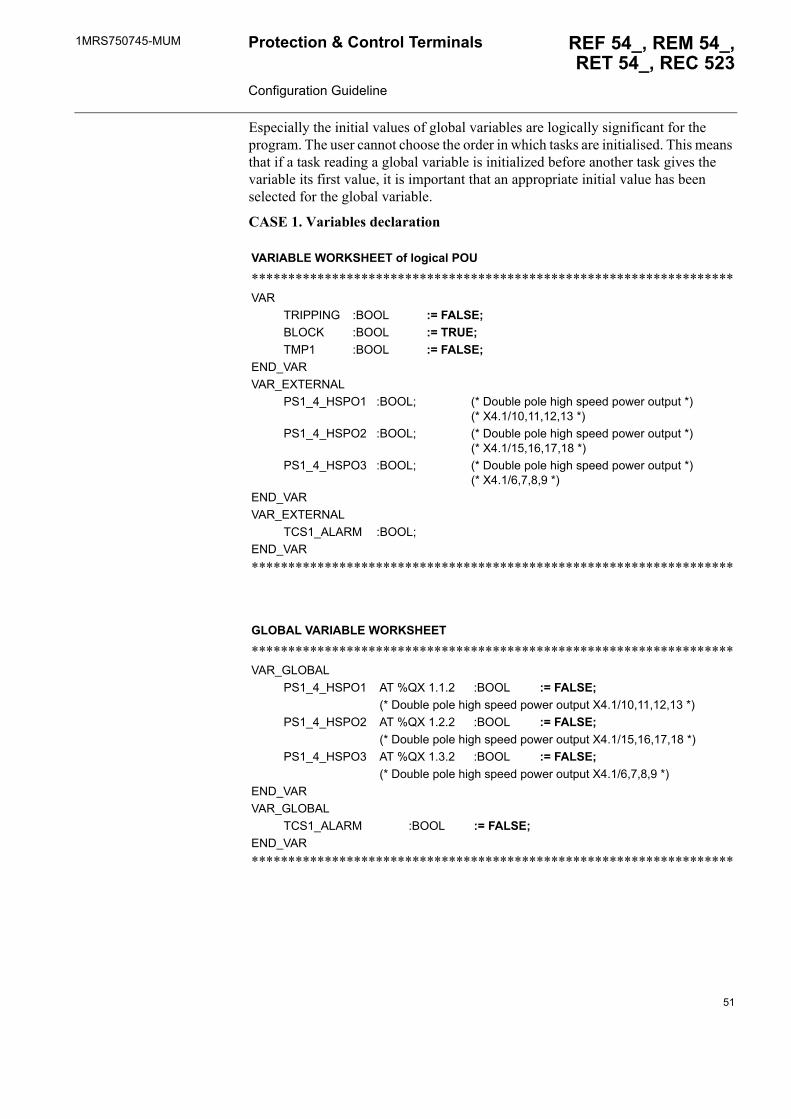
Especially the initial values of global variables are logically significant for the program. The user cannot choose the order in which tasks are initialised. This means that if a task reading a global variable is initialized before another task gives the variable its first value, it is important that an appropriate initial value has been selected for the global variable.
CASE 1. Variables declaration
VARIABLE WORKSHEET of logical POU
******************************************************************VAR
TRIPPING :BOOL := FALSE; BLOCK :BOOL := TRUE; TMP1 :BOOL := FALSE;
END_VARVAR_EXTERNAL
PS1_4_HSPO1 :BOOL; (* Double pole high speed power output *)(* X4.1/10,11,12,13 *)
PS1_4_HSPO2 :BOOL; (* Double pole high speed power output *)(* X4.1/15,16,17,18 *)
PS1_4_HSPO3 :BOOL; (* Double pole high speed power output *)(* X4.1/6,7,8,9 *)
END_VARVAR_EXTERNAL
TCS1_ALARM :BOOL;END_VAR******************************************************************
GLOBAL VARIABLE WORKSHEET
******************************************************************VAR_GLOBAL
PS1_4_HSPO1 AT %QX 1.1.2 :BOOL := FALSE; (* Double pole high speed power output X4.1/10,11,12,13 *)
PS1_4_HSPO2 AT %QX 1.2.2 :BOOL := FALSE; (* Double pole high speed power output X4.1/15,16,17,18 *)
PS1_4_HSPO3 AT %QX 1.3.2 :BOOL := FALSE; (* Double pole high speed power output X4.1/6,7,8,9 *)
END_VARVAR_GLOBAL
TCS1_ALARM :BOOL := FALSE; END_VAR******************************************************************
51
1MRS750745-MUMProtection & Control Terminals Configuration Guideline
REF 54_, REM 54_, RET 54_, REC 523
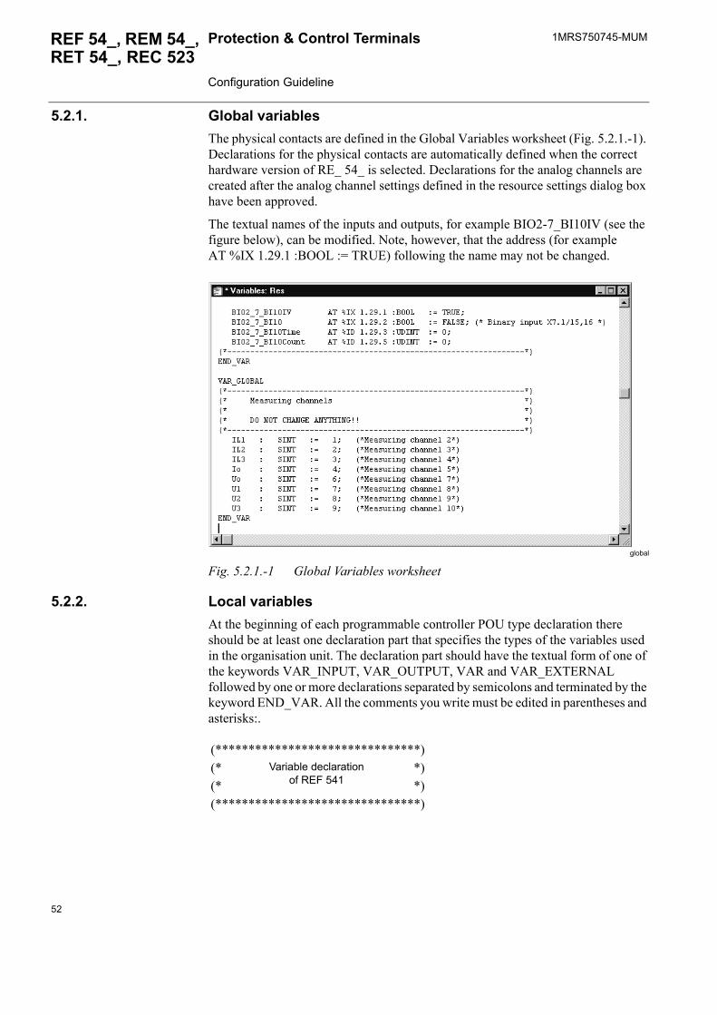
5.2.1. Global variablesThe physical contacts are defined in the Global Variables worksheet (Fig. 5.2.1.-1). Declarations for the physical contacts are automatically defined when the correct hardware version of RE_ 54_ is selected. Declarations for the analog channels are created after the analog channel settings defined in the resource settings dialog box have been approved.
The textual names of the inputs and outputs, for example BIO2-7_BI10IV (see the figure below), can be modified. Note, however, that the address (for example AT %IX 1.29.1 :BOOL := TRUE) following the name may not be changed.
global
Fig. 5.2.1.-1 Global Variables worksheet
5.2.2. Local variablesAt the beginning of each programmable controller POU type declaration there should be at least one declaration part that specifies the types of the variables used in the organisation unit. The declaration part should have the textual form of one of the keywords VAR_INPUT, VAR_OUTPUT, VAR and VAR_EXTERNAL followed by one or more declarations separated by semicolons and terminated by the keyword END_VAR. All the comments you write must be edited in parentheses and asterisks:.
(*******************************)(* Variable declaration
of REF 541 *)
(* *)(*******************************)
52
1MRS750745-MUM REF 54_, REM 54_,RET 54_, REC 523
Protection & Control Terminals Configuration Guideline
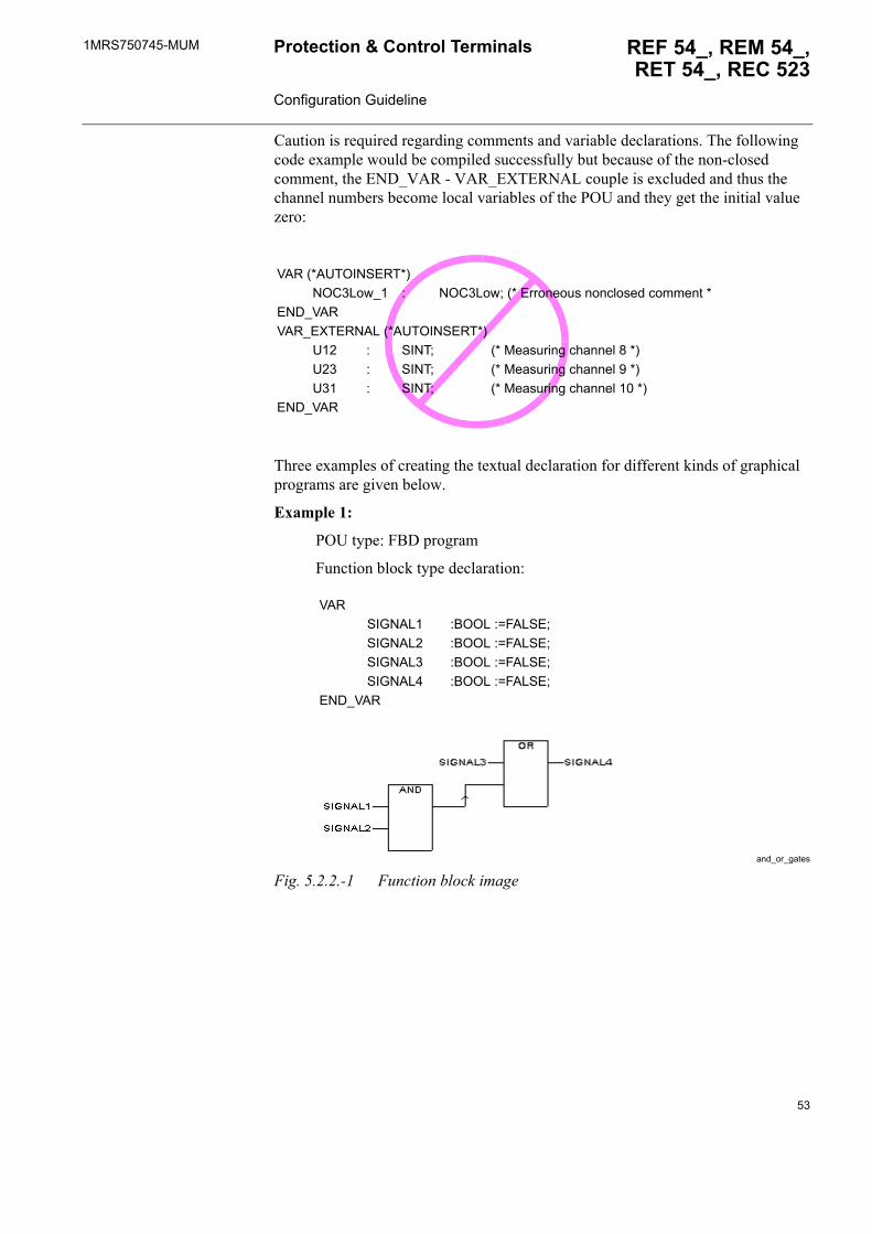
Caution is required regarding comments and variable declarations. The following code example would be compiled successfully but because of the non-closed comment, the END_VAR - VAR_EXTERNAL couple is excluded and thus the channel numbers become local variables of the POU and they get the initial value zero:
Three examples of creating the textual declaration for different kinds of graphical programs are given below.
Example 1:
POU type: FBD program
Function block type declaration:
and_or_gates
Fig. 5.2.2.-1 Function block image
VARSIGNAL1 :BOOL :=FALSE;SIGNAL2 :BOOL :=FALSE;SIGNAL3 :BOOL :=FALSE;SIGNAL4 :BOOL :=FALSE;
END_VAR
VAR (*AUTOINSERT*)NOC3Low_1 : NOC3Low; (* Erroneous nonclosed comment *
END_VARVAR_EXTERNAL (*AUTOINSERT*)
U12 : SINT; (* Measuring channel 8 *)U23 : SINT; (* Measuring channel 9 *)U31 : SINT; (* Measuring channel 10 *)
END_VAR
53
1MRS750745-MUMProtection & Control Terminals Configuration Guideline
REF 54_, REM 54_, RET 54_, REC 523
Example 2:
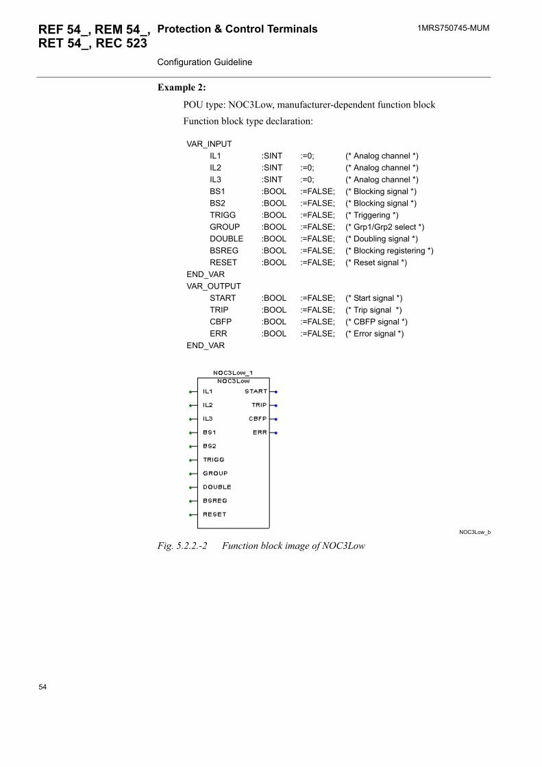
POU type: NOC3Low, manufacturer-dependent function blockFunction block type declaration:
NOC3Low_b
Fig. 5.2.2.-2 Function block image of NOC3Low
VAR_INPUTIL1 :SINT :=0; (* Analog channel *)IL2 :SINT :=0; (* Analog channel *)IL3 :SINT :=0; (* Analog channel *)BS1 :BOOL :=FALSE; (* Blocking signal *)BS2 :BOOL :=FALSE; (* Blocking signal *)TRIGG :BOOL :=FALSE; (* Triggering *)GROUP :BOOL :=FALSE; (* Grp1/Grp2 select *)DOUBLE :BOOL :=FALSE; (* Doubling signal *)BSREG :BOOL :=FALSE; (* Blocking registering *)RESET :BOOL :=FALSE; (* Reset signal *)
END_VARVAR_OUTPUT
START :BOOL :=FALSE; (* Start signal *)TRIP :BOOL :=FALSE; (* Trip signal *)CBFP :BOOL :=FALSE; (* CBFP signal *)ERR :BOOL :=FALSE; (* Error signal *)
END_VAR
54
1MRS750745-MUM REF 54_, REM 54_,RET 54_, REC 523
Protection & Control Terminals Configuration Guideline
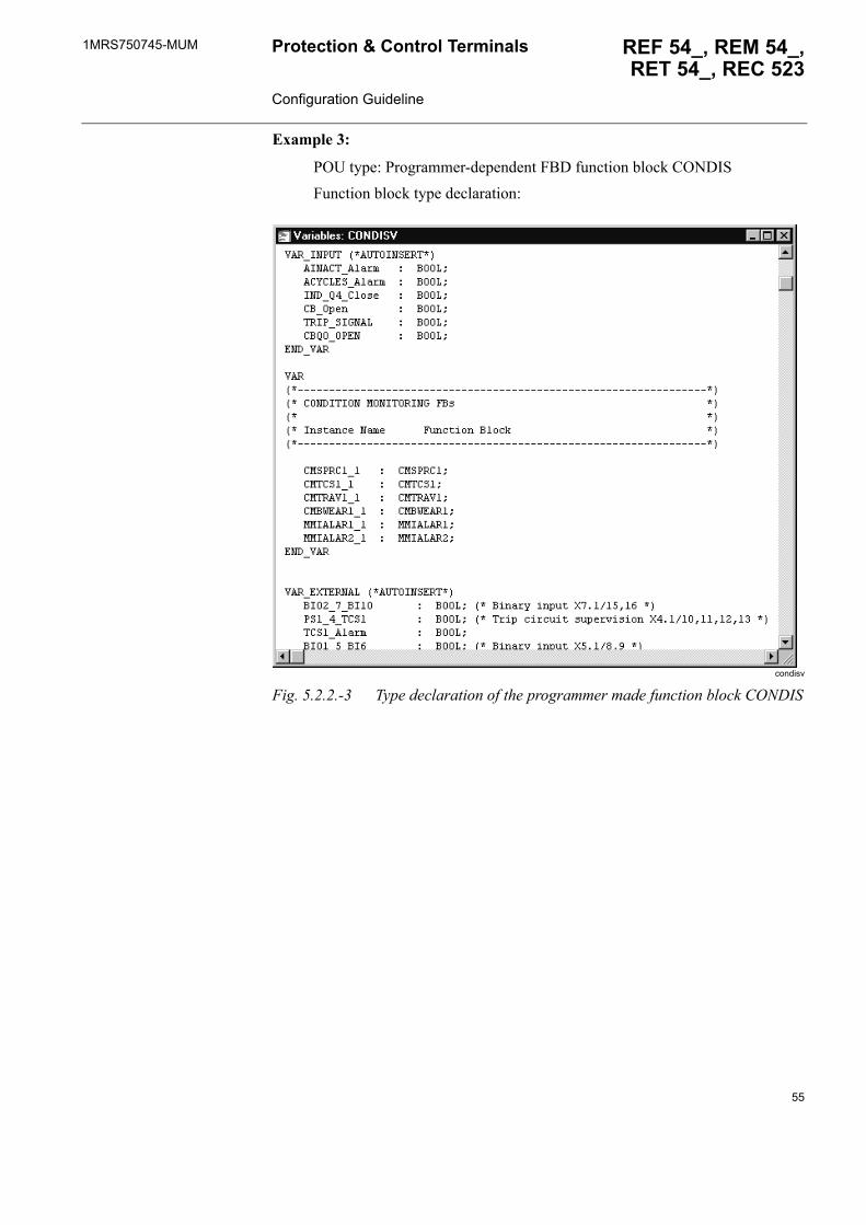
Example 3:
POU type: Programmer-dependent FBD function block CONDISFunction block type declaration:
condisv
Fig. 5.2.2.-3 Type declaration of the programmer made function block CONDIS
55
1MRS750745-MUMProtection & Control Terminals Configuration Guideline
REF 54_, REM 54_, RET 54_, REC 523
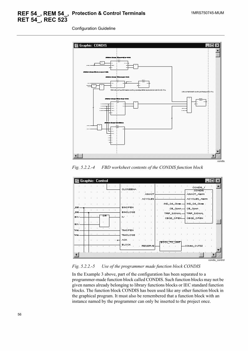
condis
Fig. 5.2.2.-4 FBD worksheet contents of the CONDIS function block
condis_control
Fig. 5.2.2.-5 Use of the programmer made function block CONDIS
In the Example 3 above, part of the configuration has been separated to a programmer-made function block called CONDIS. Such function blocks may not be given names already belonging to library functions blocks or IEC standard function blocks. The function block CONDIS has been used like any other function block in the graphical program. It must also be remembered that a function block with an instance named by the programmer can only be inserted to the project once.
56
1MRS750745-MUM REF 54_, REM 54_,RET 54_, REC 523
Protection & Control Terminals Configuration Guideline
5.3. Compiling projectIn the Relay Configuration Tool�s Make menu, select the command Build Project to compile the whole project for the first time after editing. This means compiling all POUs, global variables, resources and so on.
In the Make menu, use the Make command to compile the worksheets that have been edited. The changed worksheets are marked with an asterisk, �*�, in the project tree editor. The Make command is the standard mode for compiling and should normally be used when you have finished editing.
In the Relay Configuration Tool you can view the execution order of the different functions or function blocks in your worksheet. The execution order corresponds to the intermediate PLC code created while compiling. Note that the execution order can only be seen if you have already compiled the worksheet by using the menu command Make > Compile Worksheet.
5.4. Add-on protocolIf an add-on protocol is used, the protocol mapping must be created by using the Protocol Mapping Tool (PMT). For more information, refer to the documents in Section 1.8. Related documents.
5.5. Downloading the configurationAfter the configuration has been built and succesfully compiled in the Relay Configuration Tool and the MIMIC configuration has been designed, the project can be downloaded to the device.
It is recommended that the Build Project command is given once more just before downloading the configuration to the product.
Table 5.4.-1 Available add-on protocols
Relay version Modbus DNP 3.0 IEC 60870-5-103REF 54_ Release 2.5 XREF 54_ Release 3.0 X X XREF 54_ Release 3.5 X X XREM 54_ Release 2.5 XRET 54_ Release 3.0 X X X
REC 523 does not have any add-on protocols, but the device includes fixed protocols according to the device�s software configuration. In REC 523 revision F, the protocol interface can be modified by using the Protocol Mapping Tool. In earlier releases, the protocol interface can be modified by using the Protocol Editing Tool. These tools are included in CAP 505. For more information on the REC 523 protocols, refer to the technical reference manual of REC 523 (see Section 1.8. Related documents).
57
1MRS750745-MUMProtection & Control Terminals Configuration Guideline
REF 54_, REM 54_, RET 54_, REC 523
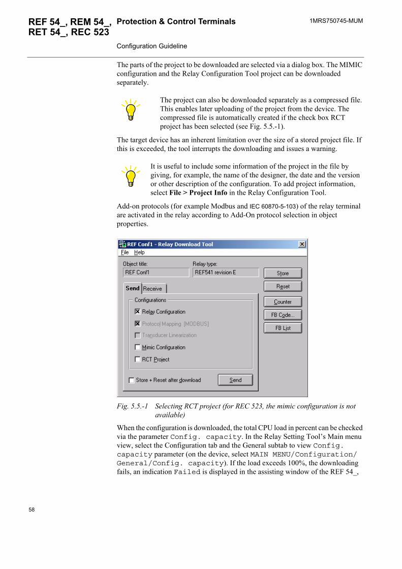
The parts of the project to be downloaded are selected via a dialog box. The MIMIC configuration and the Relay Configuration Tool project can be downloaded separately.
The target device has an inherent limitation over the size of a stored project file. If this is exceeded, the tool interrupts the downloading and issues a warning.
Add-on protocols (for example Modbus and IEC 60870-5-103) of the relay terminal are activated in the relay according to Add-On protocol selection in object properties.
Fig. 5.5.-1 Selecting RCT project (for REC 523, the mimic configuration is not available)
When the configuration is downloaded, the total CPU load in percent can be checked via the parameter Config. capacity. In the Relay Setting Tool�s Main menu view, select the Configuration tab and the General subtab to view Config. capacity parameter (on the device, select MAIN MENU/Configuration/General/Config. capacity). If the load exceeds 100%, the downloading fails, an indication Failed is displayed in the assisting window of the REF 54_,
The project can also be downloaded separately as a compressed file. This enables later uploading of the project from the device. The compressed file is automatically created if the check box RCT project has been selected (see Fig. 5.5.-1).
It is useful to include some information of the project in the file by giving, for example, the name of the designer, the date and the version or other description of the configuration. To add project information, select File > Project Info in the Relay Configuration Tool.
58
1MRS750745-MUM REF 54_, REM 54_,RET 54_, REC 523
Protection & Control Terminals Configuration Guideline
REM 54_ or RET 54_ display, and a message appears in the CAP 505. The exceeded CPU load can also be read via the parameter after a failed downloading, that is, the load value can be for example 115%.
Whenever downloading fails, a storing sequence cannot be started but the device must be reset before next downloading. Moreover, the device is automatically reset after a failed downloading when the download dialog box in the Relay Download Tool is closed.
Note that the exceeded CPU load must be checked before resetting; after the device is restarted, the parameter Config. capacity only shows the load of the previous configuration that was downloaded succesfully and has become valid again.
5.5.1. REF 54_ Release 2.5, RET 54_ and REC 523 revision F additionsThe REF 54_ Release 2.5 and later, REC 523 revision F and RET 54_ includes the following functions supported by the Configuration Download Tool:
� Relay and configuration tool compatibility checking� Improved configuration error reporting � Easier identification of the relay configuration
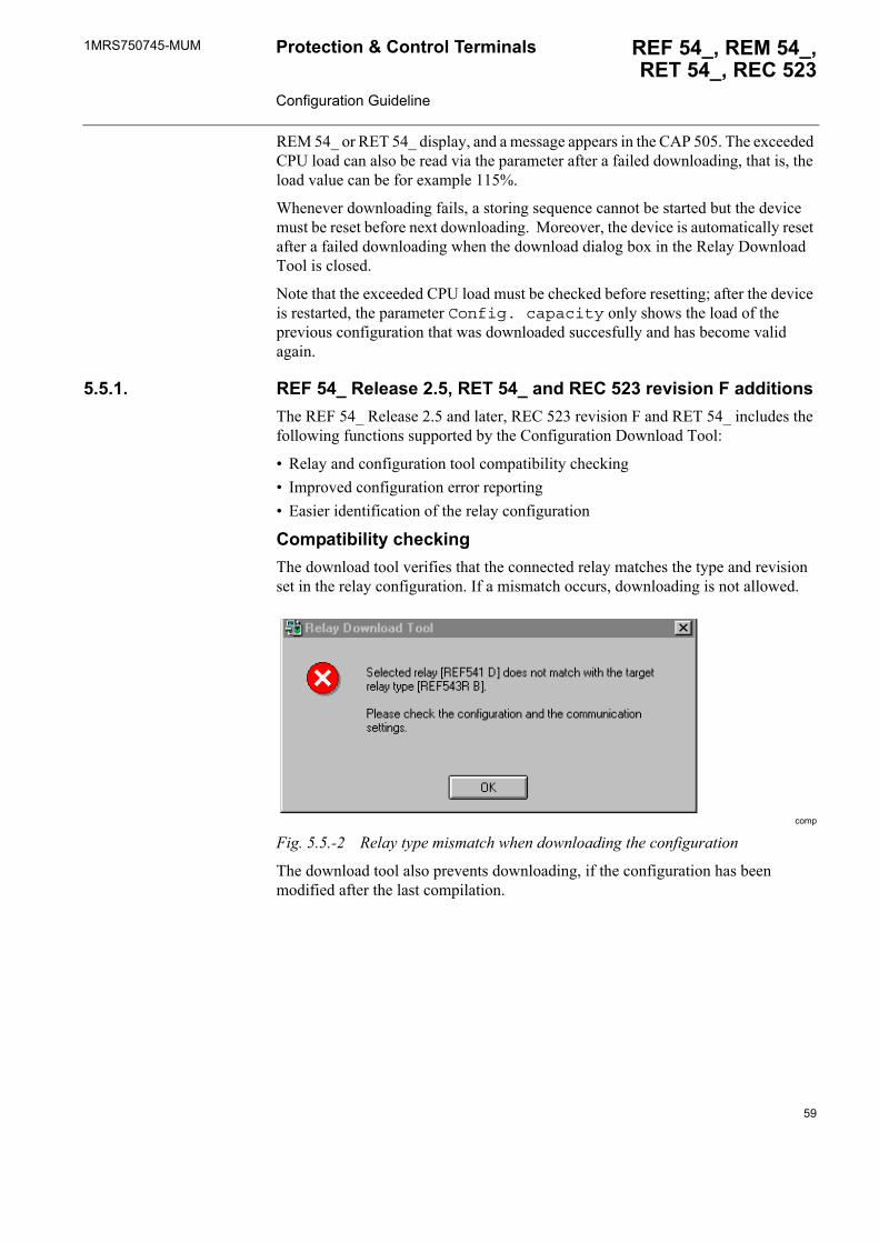
Compatibility checkingThe download tool verifies that the connected relay matches the type and revision set in the relay configuration. If a mismatch occurs, downloading is not allowed.
comp
Fig. 5.5.-2 Relay type mismatch when downloading the configuration
The download tool also prevents downloading, if the configuration has been modified after the last compilation.
59
1MRS750745-MUMProtection & Control Terminals Configuration Guideline
REF 54_, REM 54_, RET 54_, REC 523
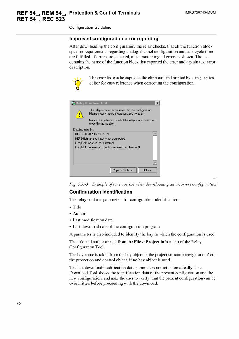
Improved configuration error reportingAfter downloading the configuration, the relay checks, that all the function block specific requirements regarding analog channel configuration and task cycle time are fulfilled. If errors are detected, a list containing all errors is shown. The list contains the name of the function block that reported the error and a plain text error description.
err
Fig. 5.5.-3 Example of an error list when downloading an incorrect configuration
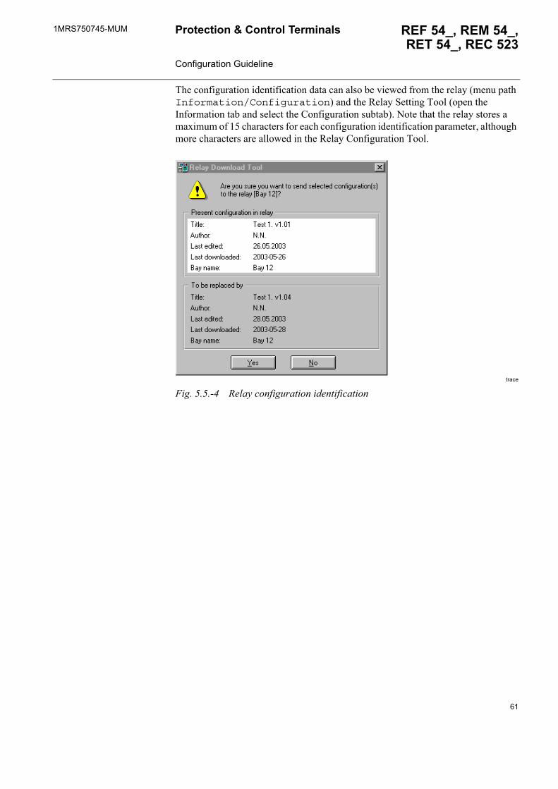
Configuration identificationThe relay contains parameters for configuration identification:
� Title� Author� Last modification date� Last download date of the configuration program
A parameter is also included to identify the bay in which the configuration is used.
The title and author are set from the File > Project info menu of the Relay Configuration Tool.
The bay name is taken from the bay object in the project structure navigator or from the protection and control object, if no bay object is used.
The last download/modification date parameters are set automatically. The Download Tool shows the identification data of the present configuration and the new configuration, and asks the user to verify, that the present configuration can be overwritten before proceeding with the download.
The error list can be copied to the clipboard and printed by using any text editor for easy reference when correcting the configuration.
60
1MRS750745-MUM REF 54_, REM 54_,RET 54_, REC 523
Protection & Control Terminals Configuration Guideline
The configuration identification data can also be viewed from the relay (menu path Information/Configuration) and the Relay Setting Tool (open the Information tab and select the Configuration subtab). Note that the relay stores a maximum of 15 characters for each configuration identification parameter, although more characters are allowed in the Relay Configuration Tool.
trace
Fig. 5.5.-4 Relay configuration identification
61

62
1MRS750745-MUM REF 54_, REM 54_,RET 54_, REC 523
Protection & Control Terminals Configuration Guideline
6. Main configuration rules
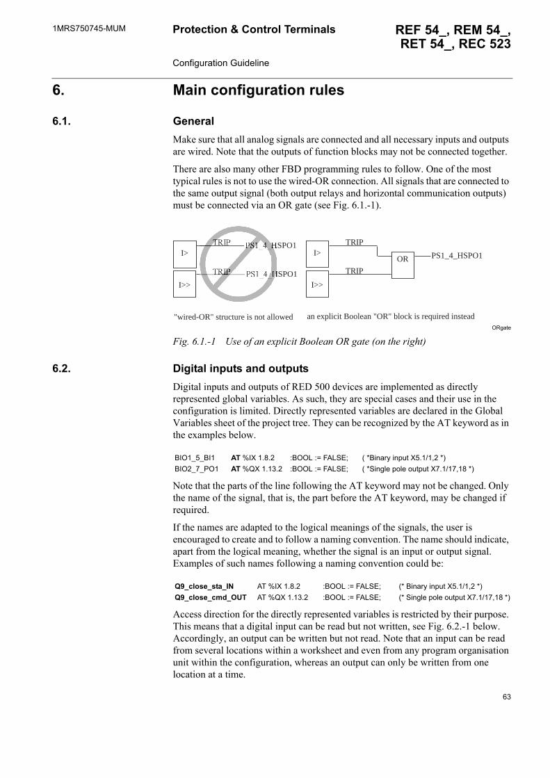
6.1. GeneralMake sure that all analog signals are connected and all necessary inputs and outputs are wired. Note that the outputs of function blocks may not be connected together.
There are also many other FBD programming rules to follow. One of the most typical rules is not to use the wired-OR connection. All signals that are connected to the same output signal (both output relays and horizontal communication outputs) must be connected via an OR gate (see Fig. 6.1.-1).
ORgate
Fig. 6.1.-1 Use of an explicit Boolean OR gate (on the right)
6.2. Digital inputs and outputsDigital inputs and outputs of RED 500 devices are implemented as directly represented global variables. As such, they are special cases and their use in the configuration is limited. Directly represented variables are declared in the Global Variables sheet of the project tree. They can be recognized by the AT keyword as in the examples below.
Note that the parts of the line following the AT keyword may not be changed. Only the name of the signal, that is, the part before the AT keyword, may be changed if required.
If the names are adapted to the logical meanings of the signals, the user is encouraged to create and to follow a naming convention. The name should indicate, apart from the logical meaning, whether the signal is an input or output signal. Examples of such names following a naming convention could be:
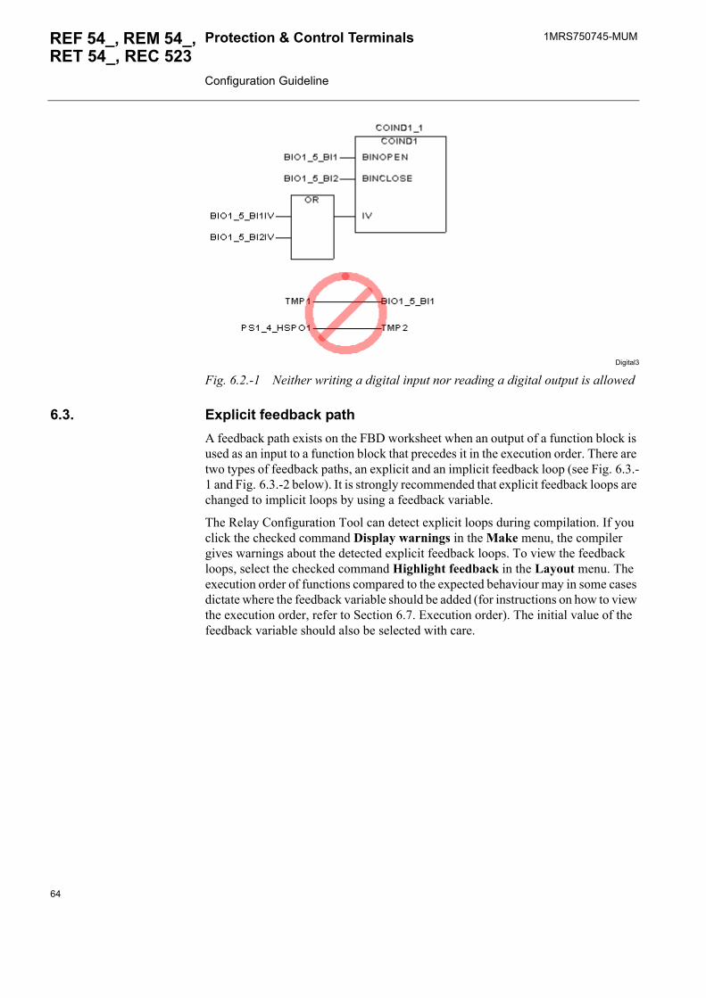
Access direction for the directly represented variables is restricted by their purpose. This means that a digital input can be read but not written, see Fig. 6.2.-1 below. Accordingly, an output can be written but not read. Note that an input can be read from several locations within a worksheet and even from any program organisation unit within the configuration, whereas an output can only be written from one location at a time.
I>
I>>
PS1_4_HSPO1
PS1_4_HSPO1
I>
I>>
TRIP
TRIP
PS1_4_HSPO1OR
"wired-OR" structure is not allowed an explicit Boolean "OR" block is required instead
BIO1_5_BI1 AT %IX 1.8.2 :BOOL := FALSE; ( *Binary input X5.1/1,2 *)BIO2_7_PO1 AT %QX 1.13.2 :BOOL := FALSE; ( *Single pole output X7.1/17,18 *)
Q9_close_sta_IN AT %IX 1.8.2 :BOOL := FALSE; (* Binary input X5.1/1,2 *)Q9_close_cmd_OUT AT %QX 1.13.2 :BOOL := FALSE; (* Single pole output X7.1/17,18 *)
63
1MRS750745-MUMProtection & Control Terminals Configuration Guideline
REF 54_, REM 54_, RET 54_, REC 523
Digital3
Fig. 6.2.-1 Neither writing a digital input nor reading a digital output is allowed
6.3. Explicit feedback pathA feedback path exists on the FBD worksheet when an output of a function block is used as an input to a function block that precedes it in the execution order. There are two types of feedback paths, an explicit and an implicit feedback loop (see Fig. 6.3.-1 and Fig. 6.3.-2 below). It is strongly recommended that explicit feedback loops are changed to implicit loops by using a feedback variable.
The Relay Configuration Tool can detect explicit loops during compilation. If you click the checked command Display warnings in the Make menu, the compiler gives warnings about the detected explicit feedback loops. To view the feedback loops, select the checked command Highlight feedback in the Layout menu. The execution order of functions compared to the expected behaviour may in some cases dictate where the feedback variable should be added (for instructions on how to view the execution order, refer to Section 6.7. Execution order). The initial value of the feedback variable should also be selected with care.
64
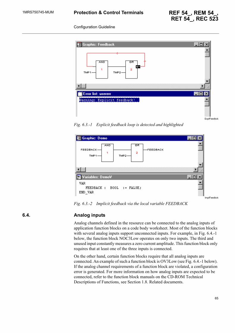
1MRS750745-MUM REF 54_, REM 54_,RET 54_, REC 523
Protection & Control Terminals Configuration Guideline
ExplFeedbck
Fig. 6.3.-1 Explicit feedback loop is detected and highlighted
ImplFeedbck
Fig. 6.3.-2 Implicit feedback via the local variable FEEDBACK
6.4. Analog inputsAnalog channels defined in the resource can be connected to the analog inputs of application function blocks on a code body worksheet. Most of the function blocks with several analog inputs support unconnected inputs. For example, in Fig. 6.4.-1 below, the function block NOC3Low operates on only two inputs. The third and unused input constantly measures a zero current amplitude. This function block only requires that at least one of the three inputs is connected.
On the other hand, certain function blocks require that all analog inputs are connected. An example of such a function block is OV3Low (see Fig. 6.4.-1 below). If the analog channel requirements of a function block are violated, a configuration error is generated. For more information on how analog inputs are expected to be connected, refer to the function block manuals on the CD-ROM Technical Descriptions of Functions, see Section 1.8. Related documents.
65
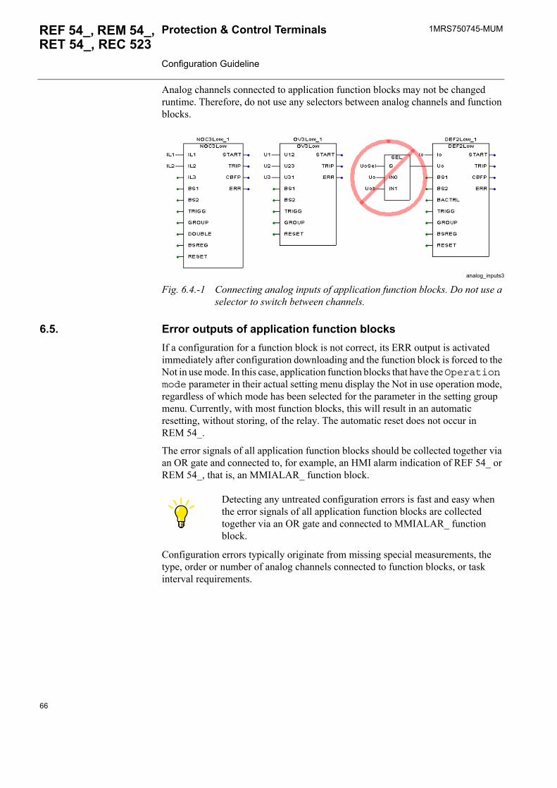
1MRS750745-MUMProtection & Control Terminals Configuration Guideline
REF 54_, REM 54_, RET 54_, REC 523
Analog channels connected to application function blocks may not be changed runtime. Therefore, do not use any selectors between analog channels and function blocks.
analog_inputs3
Fig. 6.4.-1 Connecting analog inputs of application function blocks. Do not use a selector to switch between channels.
6.5. Error outputs of application function blocksIf a configuration for a function block is not correct, its ERR output is activated immediately after configuration downloading and the function block is forced to the Not in use mode. In this case, application function blocks that have the Operation mode parameter in their actual setting menu display the Not in use operation mode, regardless of which mode has been selected for the parameter in the setting group menu. Currently, with most function blocks, this will result in an automatic resetting, without storing, of the relay. The automatic reset does not occur in REM 54_.
The error signals of all application function blocks should be collected together via an OR gate and connected to, for example, an HMI alarm indication of REF 54_ or REM 54_, that is, an MMIALAR_ function block.
Configuration errors typically originate from missing special measurements, the type, order or number of analog channels connected to function blocks, or task interval requirements.
Detecting any untreated configuration errors is fast and easy when the error signals of all application function blocks are collected together via an OR gate and connected to MMIALAR_ function block.
66
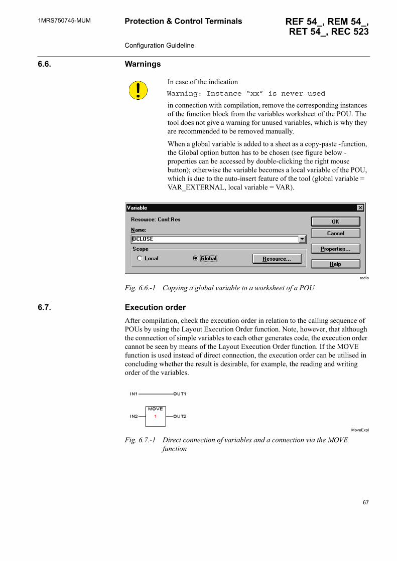
1MRS750745-MUM REF 54_, REM 54_,RET 54_, REC 523
Protection & Control Terminals Configuration Guideline
6.6. Warnings
radio
Fig. 6.6.-1 Copying a global variable to a worksheet of a POU
6.7. Execution orderAfter compilation, check the execution order in relation to the calling sequence of POUs by using the Layout Execution Order function. Note, however, that although the connection of simple variables to each other generates code, the execution order cannot be seen by means of the Layout Execution Order function. If the MOVE function is used instead of direct connection, the execution order can be utilised in concluding whether the result is desirable, for example, the reading and writing order of the variables.
MoveExpl
Fig. 6.7.-1 Direct connection of variables and a connection via the MOVE function
In case of the indication Warning: Instance “xx” is never used
in connection with compilation, remove the corresponding instances of the function block from the variables worksheet of the POU. The tool does not give a warning for unused variables, which is why they are recommended to be removed manually.
When a global variable is added to a sheet as a copy-paste -function, the Global option button has to be chosen (see figure below - properties can be accessed by double-clicking the right mouse button); otherwise the variable becomes a local variable of the POU, which is due to the auto-insert feature of the tool (global variable = VAR_EXTERNAL, local variable = VAR).
67
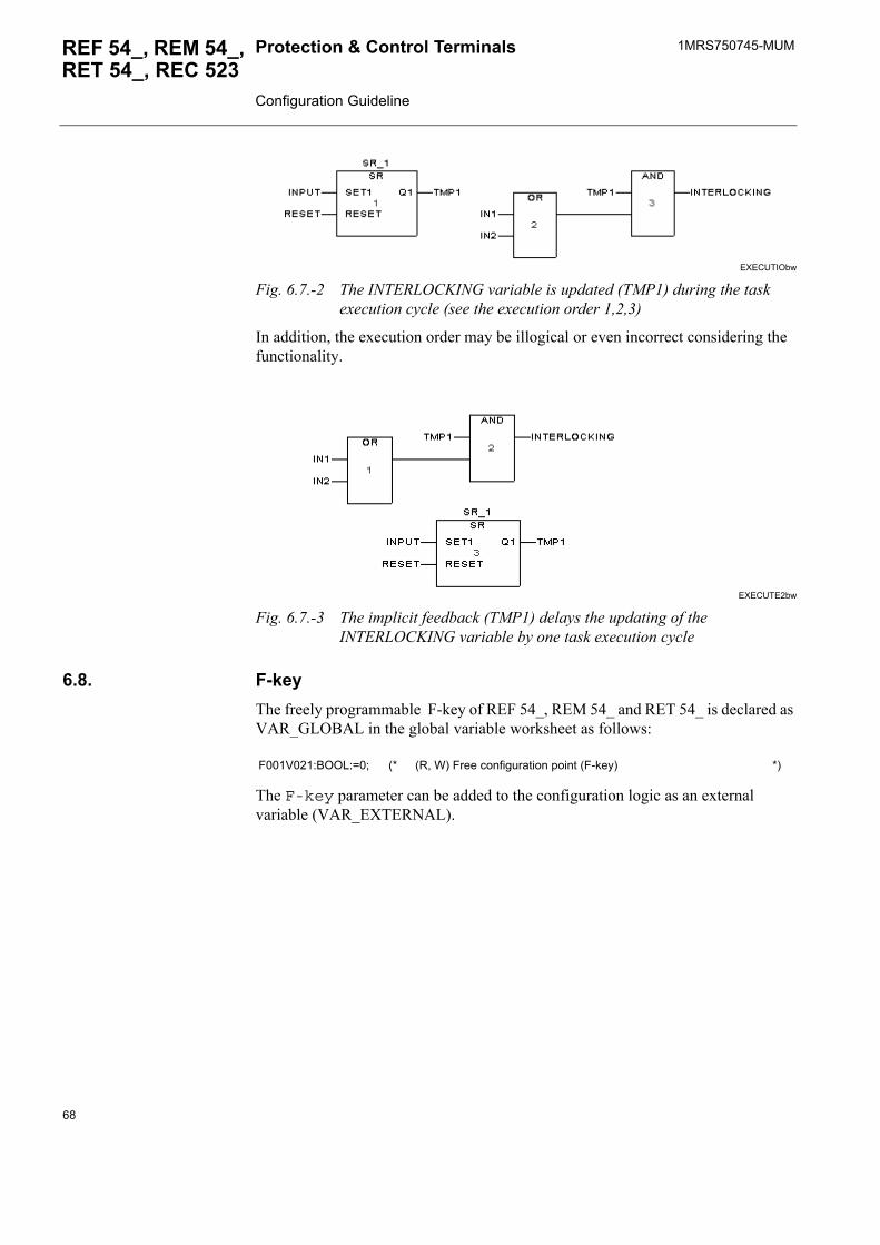
1MRS750745-MUMProtection & Control Terminals Configuration Guideline
REF 54_, REM 54_, RET 54_, REC 523
EXECUTIObw
Fig. 6.7.-2 The INTERLOCKING variable is updated (TMP1) during the task execution cycle (see the execution order 1,2,3)
In addition, the execution order may be illogical or even incorrect considering the functionality.
EXECUTE2bw
Fig. 6.7.-3 The implicit feedback (TMP1) delays the updating of the INTERLOCKING variable by one task execution cycle
6.8. F-keyThe freely programmable F-key of REF 54_, REM 54_ and RET 54_ is declared as VAR_GLOBAL in the global variable worksheet as follows:
The F-key parameter can be added to the configuration logic as an external variable (VAR_EXTERNAL).
F001V021:BOOL:=0; (* (R, W) Free configuration point (F-key) *)
68
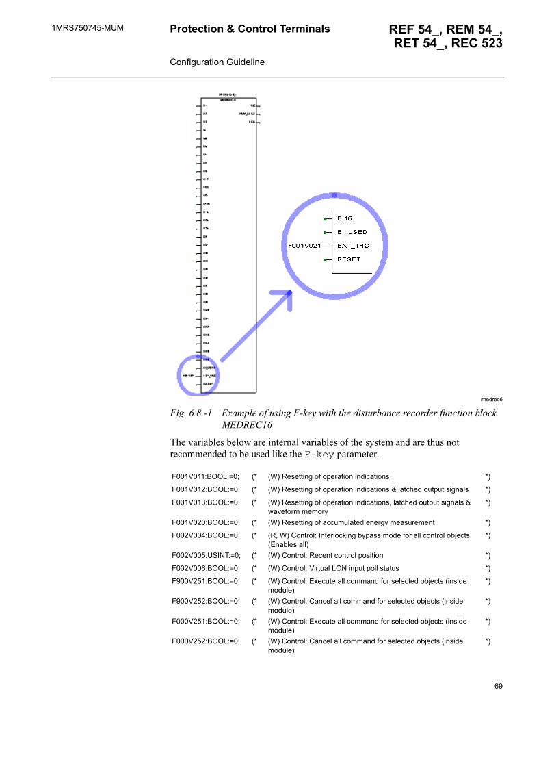
1MRS750745-MUM REF 54_, REM 54_,RET 54_, REC 523
Protection & Control Terminals Configuration Guideline
medrec6
Fig. 6.8.-1 Example of using F-key with the disturbance recorder function block MEDREC16
The variables below are internal variables of the system and are thus not recommended to be used like the F-key parameter.
F001V011:BOOL:=0; (* (W) Resetting of operation indications *)
F001V012:BOOL:=0; (* (W) Resetting of operation indications & latched output signals *)
F001V013:BOOL:=0; (* (W) Resetting of operation indications, latched output signals & waveform memory
*)
F001V020:BOOL:=0; (* (W) Resetting of accumulated energy measurement *)
F002V004:BOOL:=0; (* (R, W) Control: Interlocking bypass mode for all control objects (Enables all)
*)
F002V005:USINT:=0; (* (W) Control: Recent control position *)
F002V006:BOOL:=0; (* (W) Control: Virtual LON input poll status *)
F900V251:BOOL:=0; (* (W) Control: Execute all command for selected objects (inside module)
*)
F900V252:BOOL:=0; (* (W) Control: Cancel all command for selected objects (inside module)
*)
F000V251:BOOL:=0; (* (W) Control: Execute all command for selected objects (inside module)
*)
F000V252:BOOL:=0; (* (W) Control: Cancel all command for selected objects (inside module)
*)
69

70
1MRS750745-MUM REF 54_, REM 54_,RET 54_, REC 523
Protection & Control Terminals Configuration Guideline
7. Engineering tips
7.1. Horizontal communicationThis example includes four (4) bays. The logic is basically the same in every bay. The intention of this guideline is to point out how to ensure the horizontal inter-bay communication, including correct state indication of control objects via LON communication. The logic also includes an alarm function in case of a broken fibre optic. Incorrect updating of interlocking information blocks the control of objects, but the blocking can be bypassed by setting the device to the bypass mode.
7.1.1. Guideline for using LON NV-variables in PLC logicCommunication between terminals is executed by using the communication input and output signals (global variables COMM_IN_ and COMM_OUT_). The logic must be designed in a Relay Configuration Tool project. The LON network variable bindings can be created with the LON Network Tool.
Communication inputs and outputs are bound to each other on a one-to-one basis by means of unacknowledged repeated unicast service. The signals are named so that the number at the end of COMM_OUT_ (for example COMM_OUT2) denotes the bay to which the signal is sent. Accordingly, the number at the end of COMM_IN_ denotes the bay from which the signal is received. This way, COMM_OUT2 of bay 1 is bound to COMM_IN1 of bay 2.
7.1.1.1. COMM_INCOMM_IN_ signals are converted into Boolean logic mode by INT2BOOL function blocks. The B0 output signal (BLOCK1) in an INT2BOOL function block is used for blocking the control of objects except for the one that is sending the signal. In other words, only one object can be controlled at a time. Furthermore, Comm-Check_ signals are used for checking the condition of fibre optics. Signals for bay interlocking are also received. See Fig. 7.1.1.1.-1.
71
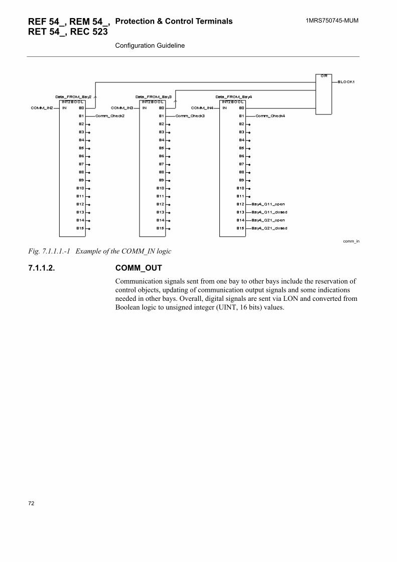
1MRS750745-MUMProtection & Control Terminals Configuration Guideline
REF 54_, REM 54_, RET 54_, REC 523
comm_in
Fig. 7.1.1.1.-1 Example of the COMM_IN logic
7.1.1.2. COMM_OUTCommunication signals sent from one bay to other bays include the reservation of control objects, updating of communication output signals and some indications needed in other bays. Overall, digital signals are sent via LON and converted from Boolean logic to unsigned integer (UINT, 16 bits) values.
72
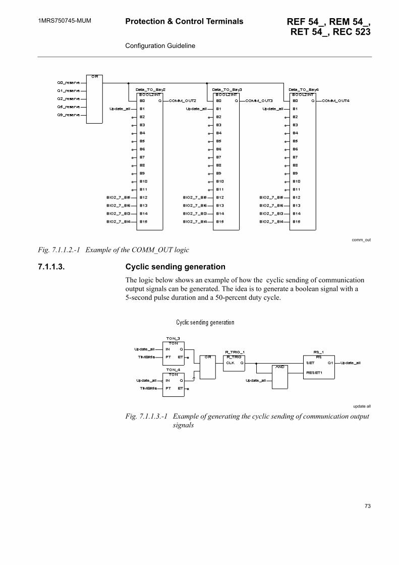
1MRS750745-MUM REF 54_, REM 54_,RET 54_, REC 523
Protection & Control Terminals Configuration Guideline
comm_out
Fig. 7.1.1.2.-1 Example of the COMM_OUT logic
7.1.1.3. Cyclic sending generationThe logic below shows an example of how the cyclic sending of communication output signals can be generated. The idea is to generate a boolean signal with a 5-second pulse duration and a 50-percent duty cycle.
update all
Fig. 7.1.1.3.-1 Example of generating the cyclic sending of communication output signals
73
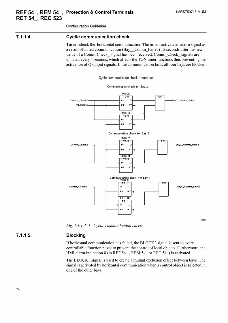
1MRS750745-MUMProtection & Control Terminals Configuration Guideline
REF 54_, REM 54_, RET 54_, REC 523
7.1.1.4. Cyclic communication checkTimers check the horizontal communication The timers activate an alarm signal as a result of failed communication (Bay__Comm_Failed) 15 seconds after the new value of a Comm-Check_ signal has been received. Comm_Check_ signals are updated every 5 seconds, which affects the TON timer functions thus preventing the activation of Q output signals. If the communication fails, all four bays are blocked.
check
Fig. 7.1.1.4.-1 Cyclic communication check
7.1.1.5. BlockingIf horizontal communication has failed, the BLOCK2 signal is sent to every controllable function block to prevent the control of local objects. Furthermore, the HMI alarm indication 8 (in REF 54_ , REM 54_ or RET 54_) is activated.
The BLOCK1 signal is used to create a mutual exclusion effect between bays. The signal is activated by horizontal communication when a control object is selected in one of the other bays.
74
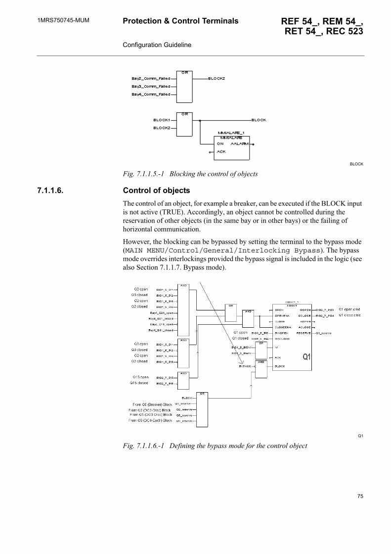
1MRS750745-MUM REF 54_, REM 54_,RET 54_, REC 523
Protection & Control Terminals Configuration Guideline
BLOCK
Fig. 7.1.1.5.-1 Blocking the control of objects
7.1.1.6. Control of objectsThe control of an object, for example a breaker, can be executed if the BLOCK input is not active (TRUE). Accordingly, an object cannot be controlled during the reservation of other objects (in the same bay or in other bays) or the failing of horizontal communication.
However, the blocking can be bypassed by setting the terminal to the bypass mode (MAIN MENU/Control/General/Interlocking Bypass). The bypass mode overrides interlockings provided the bypass signal is included in the logic (see also Section 7.1.1.7. Bypass mode).
Q1
Fig. 7.1.1.6.-1 Defining the bypass mode for the control object
75
1MRS750745-MUMProtection & Control Terminals Configuration Guideline
REF 54_, REM 54_, RET 54_, REC 523
7.1.1.7. Bypass modeThe bypass mode signal can be generated in the logic via the COLOCAT function block. After activation of the bypass mode, the BYPASS signal is active and therefore prevents activation of the BLOCK input.
bypass
Fig. 7.1.1.7.-1 Generation of the bypass mode signal
7.2. Events from the measurement function blocksSPA protocol usedMeasurement values have to be polled because they are not sent with events. Thereby the delta supervision events of the measurement function blocks can be masked off.
If limit supervision is set to be done by RTU, the limit event sending must be allowed in event masks. In this case, the client is informed of the activation and resetting of each limit with the corresponding event code numbers.
LON protocol usedEach measured variable is individualized by an IEC address. Measurement values and the corresponding IEC addresses are sent to a client, for example to MicroSCADA, with both delta supervision events and limit supervision events.
When the warning and alarm limit supervision is active, the priority for limit event sending is higher than that for delta event sending if both type of events are sent concurrently. Concurrent event sending appears, for example, when a measured value changes considerably during a short period, for example when a circuit breaker is closed or opened. This causes problems if limit supervision events have been masked off since the client does not receive all measurement values even if major changes have taken place.
The limit supervision events are not recommended to be masked off if limit supervision is used.
76
1MRS750745-MUM REF 54_, REM 54_,RET 54_, REC 523
Protection & Control Terminals Configuration Guideline
8. APPENDIX A: Relay configuration procedure
1. Create a new project2. Create a tree structure
a) Librariesb) Logical POU framework (programs and function blocks)c) Physical Hardware
i) configurationii) resource
- hardware version- used analog channels and measurement signal types- digital inputs- power and energy measurement- condition monitoring (circuit breaker breaker wear)
iii) tasks- connection between program and task- task interval
d) Logical POU contents3. Design logics4. Check variable declarations
a) Data types and initialisersb) Instances of functions and function blocksc) Variable categories
i) VAR - END_VARii) VAR_EXTERNAL - END_VARiii) VAR_INPUT - END_VARiv) VAR_OUTPUT - END_VARv) VAR_GLOBAL - END_VAR
5. Compile a project6. If an add-on protocol (DNP 3.0 or Modbus) is used, create protocol mapping.7. Download it to the device
77

78
1MRS750745-MUM REF 54_, REM 54_,RET 54_, REC 523
Protection & Control Terminals Configuration Guideline
9. APPENDIX B: Specification for REF 54_ feeder terminal configuration
9.1. General data
This document serves as a technical specification of substation protection and is used for the configuration of REF 54_ feeder terminals.
Special requirements can be specified under �Further information� at the bottom of each page.
Project name: Date:
This specification suitable for bays: Substation name:
Feeder terminal type: Software revision
Order number:
REF54 __ __ __ __ __ __ __ __ __ __(for example REF543HC127AAAA)
Handled by: Company:
Telephone number: Fax number:
79
1MRS750745-MUMProtection & Control Terminals Configuration Guideline
REF 54_, REM 54_, RET 54_, REC 523
9.2. Electrotechnical data
9.2.1. Analog inputs
Table 9.2.1-1 Analog input channel connections
Channel Measuring devices that can be connected to the corresponding analog measuring channels
1 Rogowski sensor, voltage divider or general measurement2...5 Current transformer, Rogowski sensor, voltage divider or general measurement6 Current transformer 7...10 Voltage transfomer, Rogowski sensor, voltage divider or general measurement
Further information:
80
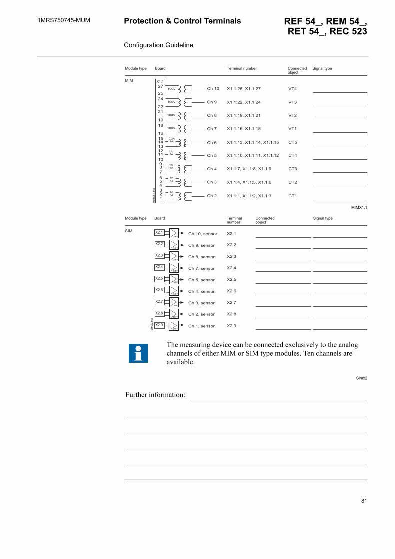
1MRS750745-MUM REF 54_, REM 54_,RET 54_, REC 523
Protection & Control Terminals Configuration Guideline
MIMX1.1
Simx2
The measuring device can be connected exclusively to the analog channels of either MIM or SIM type modules. Ten channels are available.
Further information:
����
������
����
����
����
����
����
����
����
��
������� ����
����� ��
����
����
����
��
����
���
�
���
�
����� ������� ��!�"�� #����$%���"&�$%
'�(�� �%)*����! ��%)*�
���
��+������+��
��+������+��
��+������+��
��+������+��
��+� ����+������+��
��+������+������+��
��+�����+�����+�
��+�����+�����+�
��+�����+�����+
���
��
���
���
#��
#��
#�
#��
#��#���
#��
#���
#���
#���
#���
#���
#���
#����
��
��
�
��
��
��
��
,�--
,�--
,�--
,�--
,�--
,�--
,�--
��,�--'
��
���
�
��,�--
������� �!�"��
�����
'��
���! ��%)*� #����$%���"&�$%
'�(�� �%)*�
#�����.��.��
#������.��.��
#�����.��.��
#�����.��.��
#�����.��.��
#�� ��.��.��
#�����.��.��
#�����.��.��
#�����.��.��
��
��
�
��
��
��
��
��
��
81
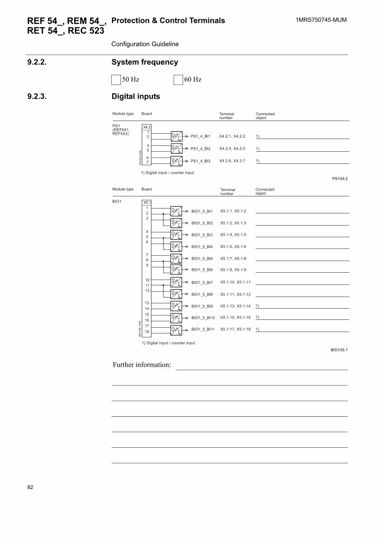
1MRS750745-MUMProtection & Control Terminals Configuration Guideline
REF 54_, REM 54_, RET 54_, REC 523
9.2.2. System frequency
9.2.3. Digital inputs
PS1X4.2
BIO1X5.1
50 Hz 60 Hz
Further information:
��
��
��
��
/'
��
���
�
������� �!�"��
����� #����$%���"&�$%
��+�����+�
��+�����+�
��+�����+�
/'�012-����12-�� 3
���! ��%)*�
�3�,�(�%� ���*!%�4�$�!�%�����*!%
�3
�3
�3
/'�5�5���
/'�5�5��
/'�5�5���
��
���
���
������
� ����������
��
��6
��
���
�
��+�����+�
��+�����+
��+�����+�
��+�����+�
��+�����+�
��+�����+�
��+������+��
��+������+��
��+� ����+��
��+������+��
��+������+��
�3�,�(�%� ���*!%�4�$�!�%�����*!%
��6�
������� �!�"��
����� #����$%���"&�$%
���! ��%)*�
�3
�3
�3
��6�5�5���
��6�5�5����
��6�5�5���
��6�5�5���
��6�5�5���
��6�5�5���
��6�5�5���
��6�5�5���
��6�5�5��
��6�5�5���
��6�5�5����
82
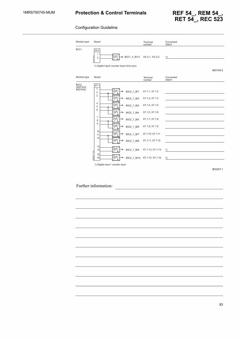
1MRS750745-MUM REF 54_, REM 54_,RET 54_, REC 523
Protection & Control Terminals Configuration Guideline
BIO1X5.2
BIO2X7.1
Further information:
��
��
��6
��
���
�
��6�
������� �!�"��
����� #����$%���"&�$%
���! ��%)*�
��6�5�5���� ��+�����+� �3
�3�,�(�%� ���*!%4�$�!�%�����*!%4�%����.)�$
��
������
� ��
����
���
���
��
��6
��
���
�
��6�012-�� �12-���3
������� �!�"��
����� #����$%���"&�$%
���! ��%)*�
�3�,�(�%� ���*!%�4�$�!�%�����*!%
�3
�3
��6�5�5���
��6�5�5���
��6�5�5���
��6�5�5���
��6�5�5���
��6�5�5���
��6�5�5��
��6�5�5���
��6�5�5����
��6�5�5��� ��+�����+�
��+�����+
��+�����+�
��+�����+�
��+�����+�
��+�����+�
��+������+��
��+������+��
��+� ����+��
��+������+��
83
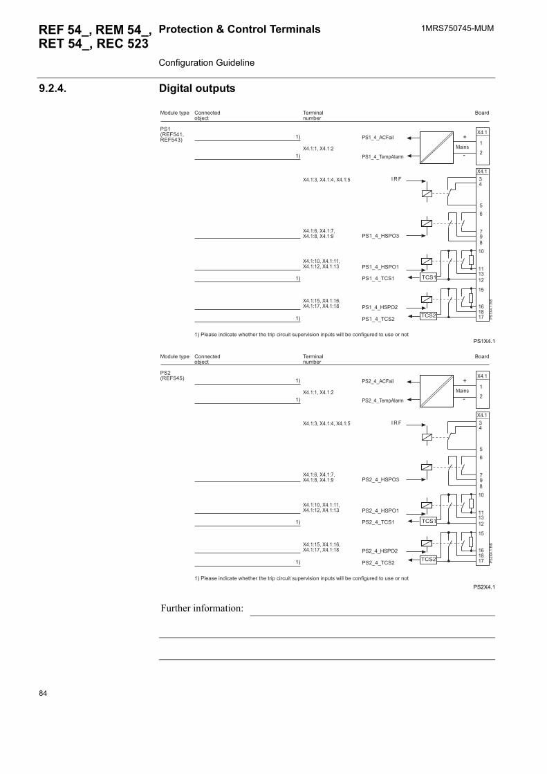
1MRS750745-MUMProtection & Control Terminals Configuration Guideline
REF 54_, REM 54_, RET 54_, REC 523
9.2.4. Digital outputs
PS1X4.1
PS2X4.1
Further information:
/'�012-����12-�� 3
������� �!�"��
�����#����$%���"&�$%
���! ��%)*�
/'
��
���
�
� 1 -
�#'�
�#'�
��
�
�
��
��
��
��� ��
��
������
�
7
��
�
�
�3
�3
�3
�3
�3�/ ��.������$�%��8��%����%���%��*�$��$!�%�.!*��9�.������*!%.�8� �"��$����(!����%��!.�������%
��+�����+�
/'�5�5:'/6
/'�5�5:'/6�
/'�5�5�#'�
/'�5�5:'/6�
/'�5�5�#'�
/'�5�5���*� ���
/'�5�5�#-��
��+ ����+�����+�
��+�����+����+�����+�
��+������+�����+������+�
��+������+�����+������+��
;����.
/'�012-���3
������� �!�"��
�����#����$%���"&�$%
���! ��%)*�
/'
��
���
�
� 1 -
�#'�
�#'�
��
�
�
��
��
��
��� ��
��
������
�
7
��
�
�
�3
�3
�3
�3
�3�/ ��.������$�%��8��%����%���%��*�$��$!�%�.!*��9�.������*!%.�8� �"��$����(!����%��!.�������%
��+�����+�
/'�5�5:'/6
/'�5�5:'/6�
/'�5�5�#'�
/'�5�5:'/6�
/'�5�5�#'�
/'�5�5���*� ���
/'�5�5�#-��
��+ ����+�����+�
��+�����+����+�����+�
��+������+�����+������+�
��+������+�����+������+��
;����.
84
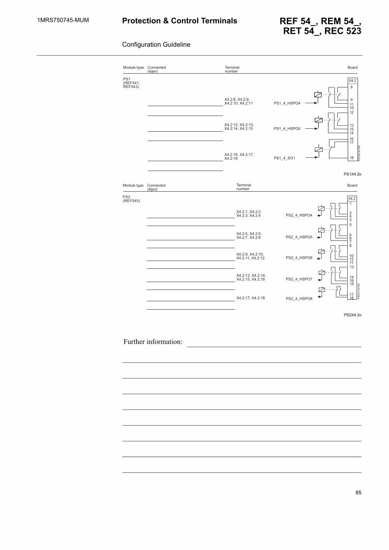
1MRS750745-MUM REF 54_, REM 54_,RET 54_, REC 523
Protection & Control Terminals Configuration Guideline
PS1X4.2o
PS2X4.2o
Further information:
/'�012-����12-�� 3
������� �!�"��
�����#����$%���"&�$%
���! ��%)*�
������
� ����
����
��
�
�
��
/'
��
����
�
/'�5�5:'/6�
/'�5�5'6�
/'�5�5:'/6���+�����+����+������+��
��+������+� ���+������+��
��+������+�����+��
��
�� �
����
�������
������
���� /
'�
���
���
/'�012-���3
������� �!�"��
�����#����$%���"&�$%
���! ��%)*�
�
/'�5�5:'/6�
/'�5�5:'/6�
/'�5�5:'/6�
/'�5�5:'/6�
/'�5�5:'/6�
��+�����+����+ ����+�
��+�����+����+�����+�
��+�����+�����+������+��
��+� ����+�����+������+��
��+������+��
85
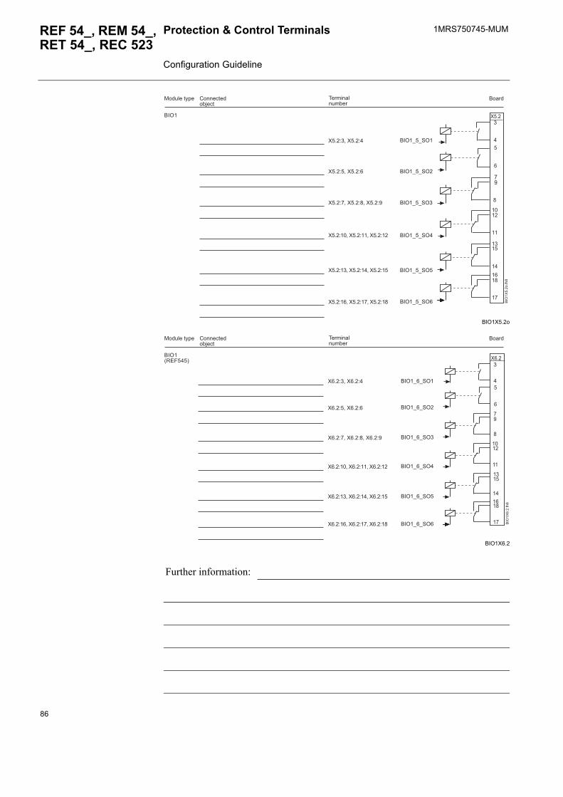
1MRS750745-MUMProtection & Control Terminals Configuration Guideline
REF 54_, REM 54_, RET 54_, REC 523
BIO1X5.2o
BIO1X6.2
Further information:
�
�
��
��
����
��
� ��
��
����
��
��
�
��6
��
����
�
��6�
������� �!�"��
�����#����$%���"&�$%
���! ��%)*�
��6�5�5'6�
��6�5�5'6�
��6�5�5'6
��6�5�5'6�
��6�5�5'6�
��6�5�5'6�
��+ ����+�
��+�����+�
��+�����+�����+�
��+������+������+��
��+� ����+������+��
��+������+������+��
�
�
��
��
����
��
� ��
������
��
��
�
��6
��
���
�
��6�012-���3
������� �!�"��
�����#����$%���"&�$%
���! ��%)*�
��6�5�5'6�
��6�5�5'6�
��6�5�5'6
��6�5�5'6�
��6�5�5'6�
��6�5�5'6�
��+ ����+�
��+�����+�
��+�����+�����+�
��+������+������+��
��+� ����+������+��
��+������+������+��
86
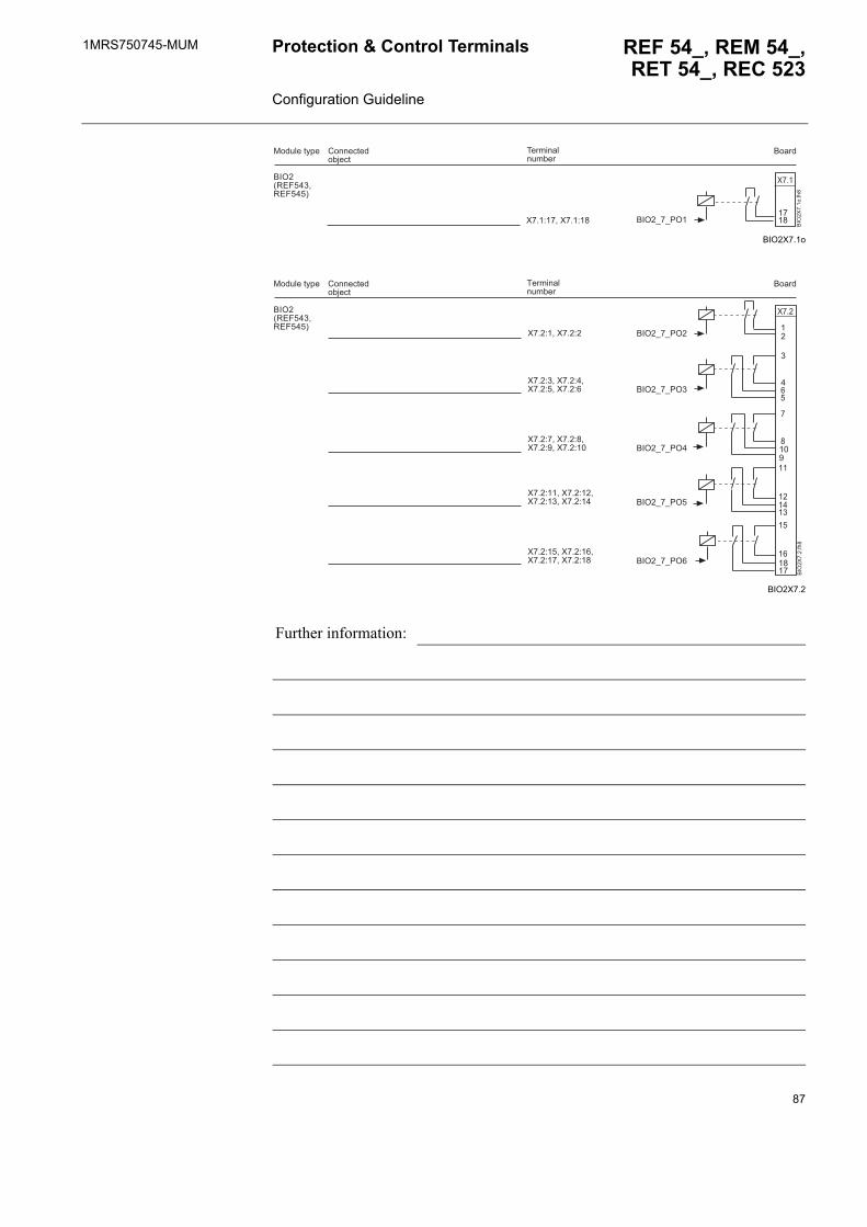
1MRS750745-MUM REF 54_, REM 54_,RET 54_, REC 523
Protection & Control Terminals Configuration Guideline
BIO2X7.1o
BIO2X7.2
Further information:
����
��
��6
��
����
�
��6�012-�� �12-���3
������� �!�"��
�����#����$%���"&�$%
���! ��%)*�
��6�5�5/6���+������+��
��
��
�
�
���
��
��
��
��
��
�
���� �
�6�
��
���
��6�012-�� �12-���3
������� �!�"��
�����#����$%���"&�$%
���! ��%)*�
���
��6�5�5/6�
��6�5�5/6
��6�5�5/6�
��6�5�5/6�
��6�5�5/6�
��+�����+�
��+ ����+����+�����+�
��+�����+����+�����+��
��+������+�����+� ����+��
��+������+�����+������+��
87
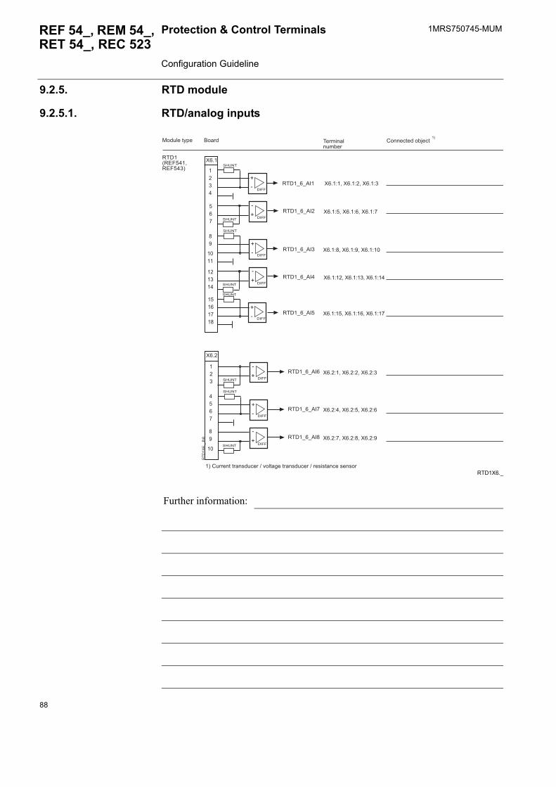
1MRS750745-MUMProtection & Control Terminals Configuration Guideline
REF 54_, REM 54_, RET 54_, REC 523
9.2.5. RTD module
9.2.5.1. RTD/analog inputs
RTD1X6._
Further information:
1�,�5�5���
1�,�5�5���
1�,�5�5��
1�,�5�5���
1�,�5�5���
1�,�5�5���
1�,�5�5���
1�,�5�5���
1�,�012-����12-�� 3
������� �!�"��
����� #����$%����"&�$%���! ��%)*�
,�--
,�--
,�--
,�--
,�--
��
����
��
��
��
,�--
,�--
,�--
��
���
�� �
��� ��
��
����
��������
;7
;7
;7
;7
':<=�
':<=�
':<=�
':<=�
':<=�
':<=�
':<=�
':<=�
7
;
7
;
7
;
7
;
1�,
��
5��
�
��+�����+�����+
��+�����+�����+�
��+�����+�����+��
��+������+� ����+��
��+������+������+��
��+�����+�����+
��+�����+�����+�
��+�����+�����+�
�3
�3�#!����%�%���.�!$���4�9� %�(��%���.�!$���4���.�.%��$��.��.��
88
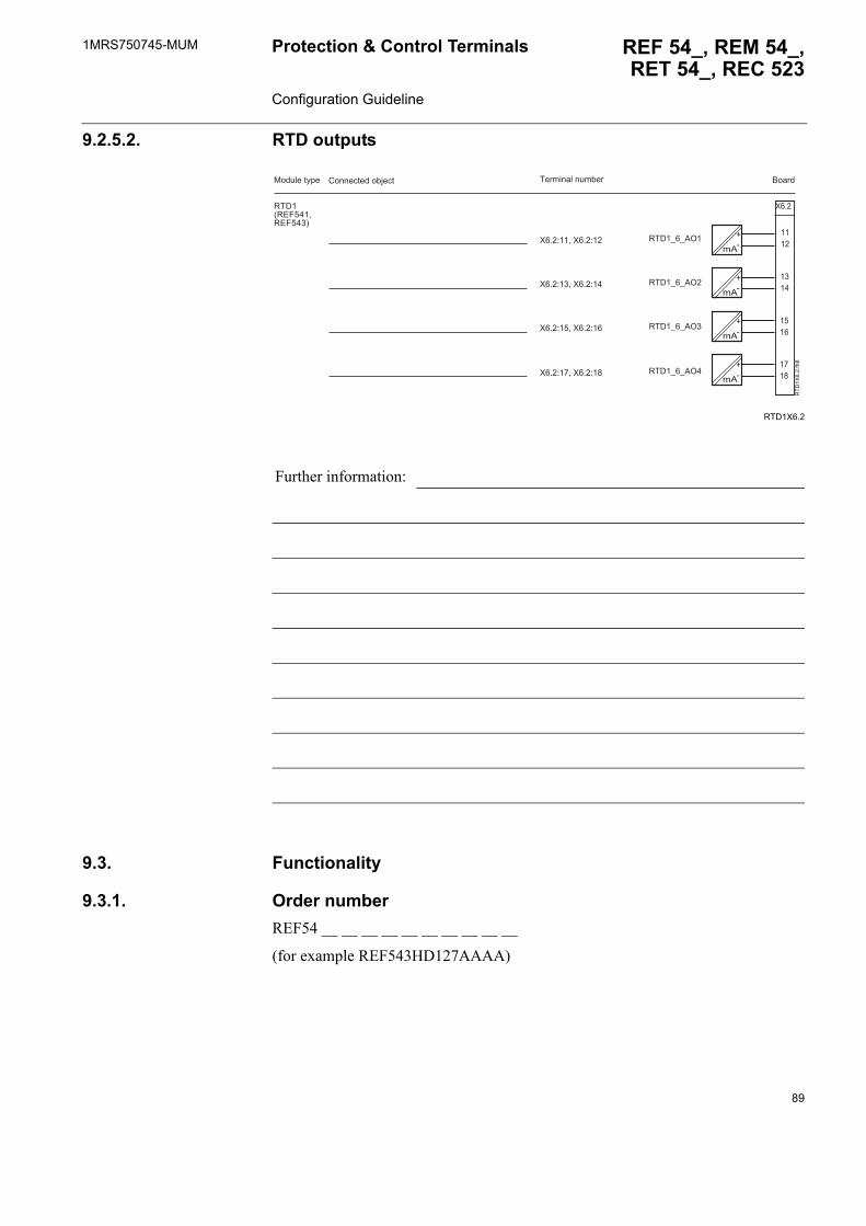
1MRS750745-MUM REF 54_, REM 54_,RET 54_, REC 523
Protection & Control Terminals Configuration Guideline
9.2.5.2. RTD outputs
RTD1X6.2
9.3. Functionality
9.3.1. Order numberREF54 __ __ __ __ __ __ __ __ __ __
(for example REF543HD127AAAA)
Further information:
��
����
� ��
����
����
��
;7
��
;7
��
;7
��
;7
1�
,�
��
���
1�,�012-����12-�� 3
������� ��!�"�� ��������! ��%)*� #����$%����"&�$%
1�,�5�5�6�
1�,�5�5�6�
1�,�5�5�6
1�,�5�5�6�
��+������+��
��+� ����+��
��+������+��
��+������+��
89
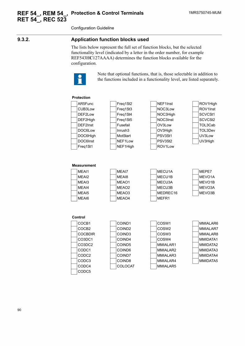
1MRS750745-MUMProtection & Control Terminals Configuration Guideline
REF 54_, REM 54_, RET 54_, REC 523
9.3.2. Application function blocks usedThe lists below represent the full set of function blocks, but the selected functionality level (indicated by a letter in the order number, for example REF543HC127AAAA) determines the function blocks available for the configuration.
Note that optional functions, that is, those selectable in addition to the functions included in a functionality level, are listed separately.
ProtectionAR5Func Freq1St2 NEF1Inst ROV1HighCUB3Low Freq1St3 NOC3Low ROV1InstDEF2Low Freq1St4 NOC3High SCVCSt1DEF2High Freq1St5 NOC3Inst SCVCSt2DEF2Inst Fusefail OV3Low TOL3CabDOC6Low Inrush3 OV3High TOL3DevDOC6High MotStart PSV3St1 UV3LowDOC6Inst NEF1Low PSV3St2 UV3HighFreq1St1 NEF1High ROV1Low
MeasurementMEAI1 MEAI7 MECU1A MEPE7MEAI2 MEAI8 MECU1B MEVO1AMEAI3 MEAO1 MECU3A MEVO1BMEAI4 MEAO2 MECU3B MEVO3AMEAI5 MEAO3 MEDREC16 MEVO3BMEAI6 MEAO4 MEFR1
ControlCOCB1 COIND1 COSW1 MMIALAR6COCB2 COIND2 COSW2 MMIALAR7COCBDIR COIND3 COSW3 MMIALAR8CO3DC1 COIND4 COSW4 MMIDATA1CO3DC2 COIND5 MMIALAR1 MMIDATA2CODC1 COIND6 MMIALAR2 MMIDATA3CODC2 COIND7 MMIALAR3 MMIDATA4CODC3 COIND8 MMIALAR4 MMIDATA5CODC4 COLOCAT MMIALAR5CODC5
90
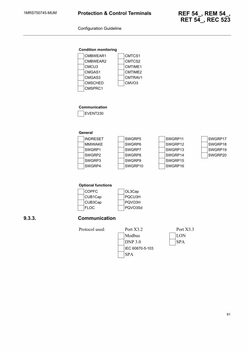
1MRS750745-MUM REF 54_, REM 54_,RET 54_, REC 523
Protection & Control Terminals Configuration Guideline
9.3.3. Communication
Condition monitoringCMBWEAR1 CMTCS1CMBWEAR2 CMTCS2CMCU3 CMTIME1CMGAS1 CMTIME2CMGAS3 CMTRAV1CMSCHED CMVO3CMSPRC1
CommunicationEVENT230
GeneralINDRESET SWGRP5 SWGRP11 SWGRP17MMIWAKE SWGRP6 SWGRP12 SWGRP18SWGRP1 SWGRP7 SWGRP13 SWGRP19SWGRP2 SWGRP8 SWGRP14 SWGRP20SWGRP3 SWGRP9 SWGRP15SWGRP4 SWGRP10 SWGRP16
Optional functionsCOPFC OL3CapCUB1Cap PQCU3HCUB3Cap PQVO3HFLOC PQVO3Sd
Protocol used: Port X3.2 Port X3.3Modbus LONDNP 3.0 SPAIEC 60870-5-103
SPA
91
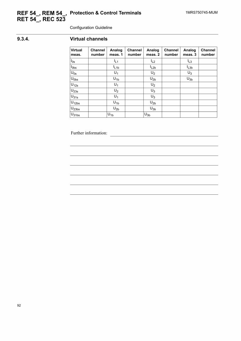
1MRS750745-MUMProtection & Control Terminals Configuration Guideline
REF 54_, REM 54_, RET 54_, REC 523
9.3.4. Virtual channels
Virtual meas.
Channel number
Analog meas. 1
Channel number
Analog meas. 2
Channel number
Analog meas. 3
Channel number
I0s IL1 IL2 IL3
I0bs IL1b IL2b IL3b
U0s U1 U2 U3
U0bs U1b U2b U3b
U12s U1 U2
U23s U2 U3
U31s U1 U3
U12bs U1b U2b
U23bs U2b U3b
U31bs U1b U3b
Further information:
92
1MRS750745-MUM REF 54_, REM 54_,RET 54_, REC 523
Protection & Control Terminals Configuration Guideline
9.4. Relay MIMIC configuration
9.4.1. Illustration of the system, MIMIC diagram
Symbol used closed open undef. 0 0 undef. 1 1
Disconnector:(truck symbols)
Circuit breaker:
Earth switch:
Further information:
93
1MRS750745-MUMProtection & Control Terminals Configuration Guideline
REF 54_, REM 54_, RET 54_, REC 523
9.4.2. Alarm LEDsFill in the table below to describe the legend text used as well as the flashing sequence and colour of the LEDs.
Table 9.4.2-1 Descriptions for legend texts and LEDs
LED OFF state ON state
Text(max. 16 characters)
Colour Flashing seq.
Text(max. 16 characters)
Colour Flashing seq.
off
gree
nye
llow
red
latc
hed,
blin
king
latc
hed,
ste
ady
non-
latc
hed,
blin
king
off
gree
nye
llow
red
latc
hed,
blin
king
latc
hed,
ste
ady
non-
latc
hed,
blin
king
1_ _ _ _ _ _ _ _ _ _ _ _ _ _ _ _ _ _ _ _ _ _ _ _ _ _ _ _ _ _ _ _
2_ _ _ _ _ _ _ _ _ _ _ _ _ _ _ _ _ _ _ _ _ _ _ _ _ _ _ _ _ _ _ _
3_ _ _ _ _ _ _ _ _ _ _ _ _ _ _ _ _ _ _ _ _ _ _ _ _ _ _ _ _ _ _ _
4_ _ _ _ _ _ _ _ _ _ _ _ _ _ _ _ _ _ _ _ _ _ _ _ _ _ _ _ _ _ _ _
5_ _ _ _ _ _ _ _ _ _ _ _ _ _ _ _ _ _ _ _ _ _ _ _ _ _ _ _ _ _ _ _
6_ _ _ _ _ _ _ _ _ _ _ _ _ _ _ _ _ _ _ _ _ _ _ _ _ _ _ _ _ _ _ _
7_ _ _ _ _ _ _ _ _ _ _ _ _ _ _ _ _ _ _ _ _ _ _ _ _ _ _ _ _ _ _ _
8_ _ _ _ _ _ _ _ _ _ _ _ _ _ _ _ _ _ _ _ _ _ _ _ _ _ _ _ _ _ _ _
Interlocking_ _ _ _ _ _ _ _ _ _ _ _ _ _ _ _ X X
Control test mode_ _ _ _ _ _ _ _ _ _ _ _ _ _ _ _ X X
Further information:
94
1MRS750745-MUM REF 54_, REM 54_,RET 54_, REC 523
Protection & Control Terminals Configuration Guideline
9.5. Functionality logicPlease specify the required special PLC logic functionality (see the examples below), by drawing or otherwise, on separate sheets and enclose all additional information with this document (Specification for Feeder Terminal Configuration).
Example 1: Earthing sequence
Earthing of the outgoing feeder can be done by a circuit breaker when an earthing sequence is activated, an earthing switch is earthed and no voltage is measured. If all conditions are fulfilled, the circuit breaker can be closed after 1 second. The figure below shows the implementation of the desired logic.
Earthing
Example 2: Usage of the F-key and a software switch
F key
95
1MRS750745-MUMProtection & Control Terminals Configuration Guideline
REF 54_, REM 54_, RET 54_, REC 523
Example 3: Voltage measurement in the MIMIC view
Phase-to-phase voltage must be shown in voltages [V] in the MIMIC view.
Voltage
9.6. Feeder terminal settingsResponsibility:
The end user defines the feeder terminal settingsFeeder terminal settings according to the turn-key principle
The setting of the parameters is not part of the configuration. The end user will normally be responsible for the setting parameters.
Further information:
96
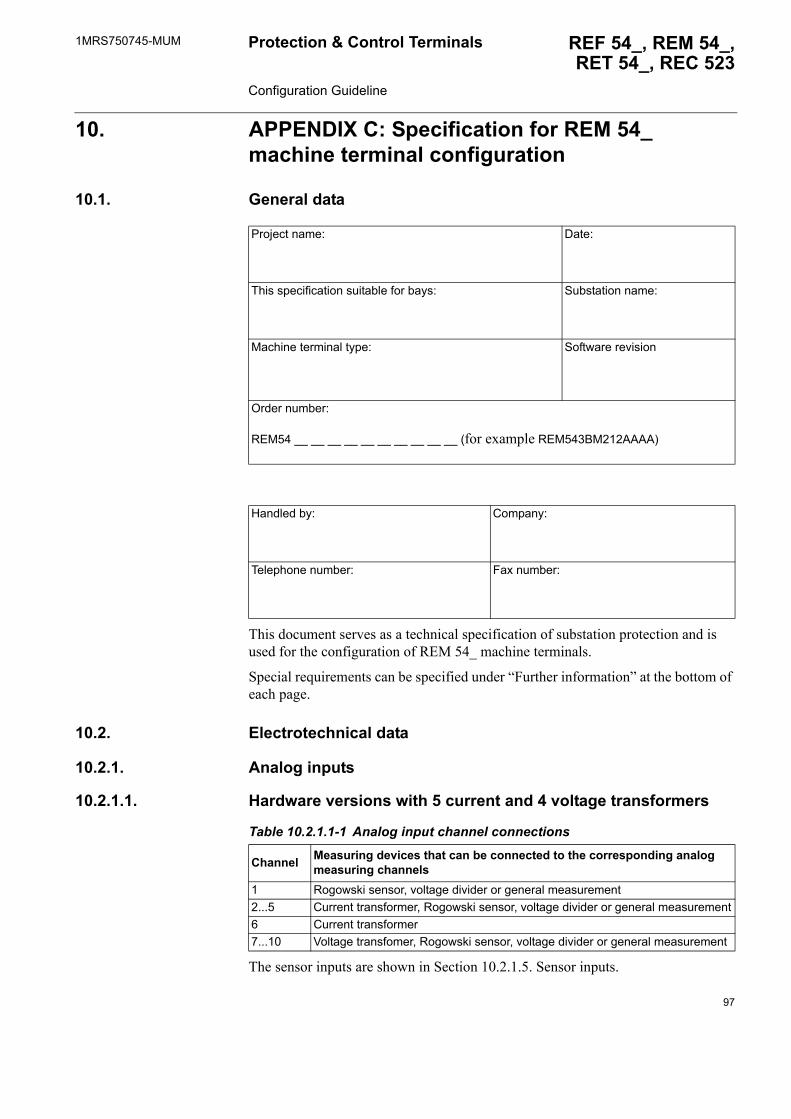
1MRS750745-MUM REF 54_, REM 54_,RET 54_, REC 523
Protection & Control Terminals Configuration Guideline
10. APPENDIX C: Specification for REM 54_ machine terminal configuration
10.1. General data
This document serves as a technical specification of substation protection and is used for the configuration of REM 54_ machine terminals.
Special requirements can be specified under �Further information� at the bottom of each page.
10.2. Electrotechnical data
10.2.1. Analog inputs
10.2.1.1. Hardware versions with 5 current and 4 voltage transformers
The sensor inputs are shown in Section 10.2.1.5. Sensor inputs.
Project name: Date:
This specification suitable for bays: Substation name:
Machine terminal type: Software revision
Order number:
REM54 __ __ __ __ __ __ __ __ __ __ (for example REM543BM212AAAA)
Handled by: Company:
Telephone number: Fax number:
Table 10.2.1.1-1 Analog input channel connections
Channel Measuring devices that can be connected to the corresponding analog measuring channels
1 Rogowski sensor, voltage divider or general measurement2...5 Current transformer, Rogowski sensor, voltage divider or general measurement6 Current transformer 7...10 Voltage transfomer, Rogowski sensor, voltage divider or general measurement
97
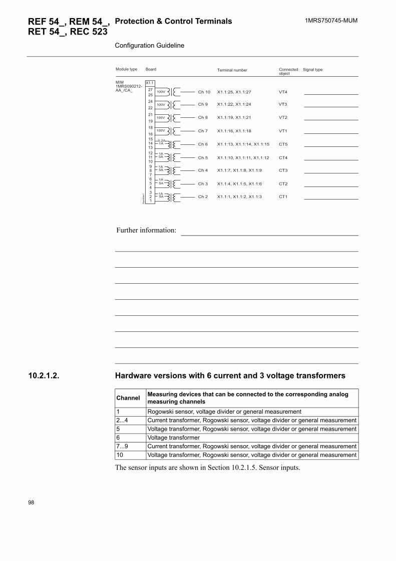
1MRS750745-MUMProtection & Control Terminals Configuration Guideline
REF 54_, REM 54_, RET 54_, REC 523
10.2.1.2. Hardware versions with 6 current and 3 voltage transformers
The sensor inputs are shown in Section 10.2.1.5. Sensor inputs.
Further information:
�����1'������7��54#�5
������� ��!�"������� #����$%���"&�$%
���! ��%)*� '�(�� �%)*�
����
����
����
����
����
����
����
����
��
1��
���
�
����
��
��
��
��
��
������� ������������ ��
����� #���
#���
#���
#���
#����
#���
#��
#���
#���
#��
���
���
��
���
#��
#��
#�
#��
��+������+��
��+������+��
��+������+��
��+������+��
��+� ����+������+��
��+������+������+��
��+�����+�����+�
��+�����+�����+�
��+�����+�����+
Channel Measuring devices that can be connected to the corresponding analog measuring channels
1 Rogowski sensor, voltage divider or general measurement2...4 Current transformer, Rogowski sensor, voltage divider or general measurement5 Voltage transformer, Rogowski sensor, voltage divider or general measurement6 Voltage transformer7...9 Current transformer, Rogowski sensor, voltage divider or general measurement10 Voltage transformer, Rogowski sensor, voltage divider or general measurement
98
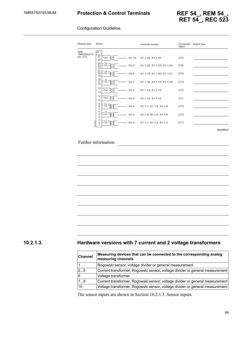
1MRS750745-MUM REF 54_, REM 54_,RET 54_, REC 523
Protection & Control Terminals Configuration Guideline
RemMim2
10.2.1.3. Hardware versions with 7 current and 2 voltage transformers
The sensor inputs are shown in Section 10.2.1.5. Sensor inputs.
Further information:
�����1'������7��54#�5
������� ��!�"������� #����$%���"&�$%
���! ��%)*� '�(�� �%)*�
����
����
����
����
����
����
����
����
����
��
1��
���
�
����
��
����
����
��
��
�
��
�������� ��
�
��
��
#���
#���
#���
#���
#����
#���
#��
#���
#���
���
#��
#��
#��
��
#��
#��
#�
���
��+������+��
��+������+� ����+��
��+������+������+��
��+������+������+��
��+� ����+��
��+������+��
��+�����+�����+�
��+�����+�����+�
��+�����+�����+
Channel Measuring devices that can be connected to the corresponding analog measuring channels
1 Rogowski sensor, voltage divider or general measurement2...5 Current transformer, Rogowski sensor, voltage divider or general measurement6 Voltage transformer 7...9 Current transformer, Rogowski sensor, voltage divider or general measurement10 Voltage transformer, Rogowski sensor, voltage divider or general measurement
99
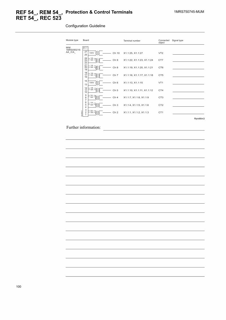
1MRS750745-MUMProtection & Control Terminals Configuration Guideline
REF 54_, REM 54_, RET 54_, REC 523
RemMim3
Further information:
�����1'������7��54#�5
������� ��!�"������� #����$%���"&�$%
���! ��%)*� '�(�� �%)*�
����
����
����
����
����
����
����
����
����
��
1��
���
����
��
����
����
��
��
�
��
�������� ��
�
��
��
��
#���
#���
#���
#���
#����
#���
#��
#���
#���
���
#��
#��
#��
���
#��
#��
#�
#��
��+������+��
��+������+� ����+��
��+������+������+��
��+������+������+��
��+� ����+��
��+������+������+��
��+�����+�����+�
��+�����+�����+�
��+�����+�����+
100
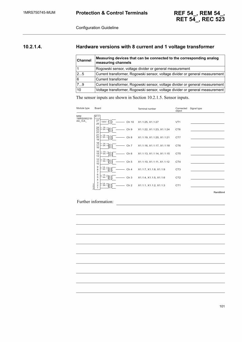
1MRS750745-MUM REF 54_, REM 54_,RET 54_, REC 523
Protection & Control Terminals Configuration Guideline
10.2.1.4. Hardware versions with 8 current and 1 voltage transformer
The sensor inputs are shown in Section 10.2.1.5. Sensor inputs.
RemMim4
Channel Measuring devices that can be connected to the corresponding analog measuring channels
1 Rogowski sensor, voltage divider or general measurement2...5 Current transformer, Rogowski sensor, voltage divider or general measurement6 Current transformer 7...9 Current transformer, Rogowski sensor, voltage divider or general measurement10 Voltage transformer, Rogowski sensor, voltage divider or general measurement
Further information:
�����1'������7��54#�5
������� ��!�"������� #����$%���"&�$%
���! ��%)*� '�(�� �%)*�
����
����
����
����
����
����
����
����
����
��
1��
���
�
����
��
����
����
��
��
� ��
�������� ��
�
��
��
��
�� #���
#���
#���
#���
#����
#���
#��
#���
#���
#��
#��
#��
#��
���
#��
#��
#�
#��
��+������+��
��+������+� ����+��
��+������+������+��
��+������+������+��
��+� ����+������+��
��+������+������+��
��+�����+�����+�
��+�����+�����+�
��+�����+�����+
101
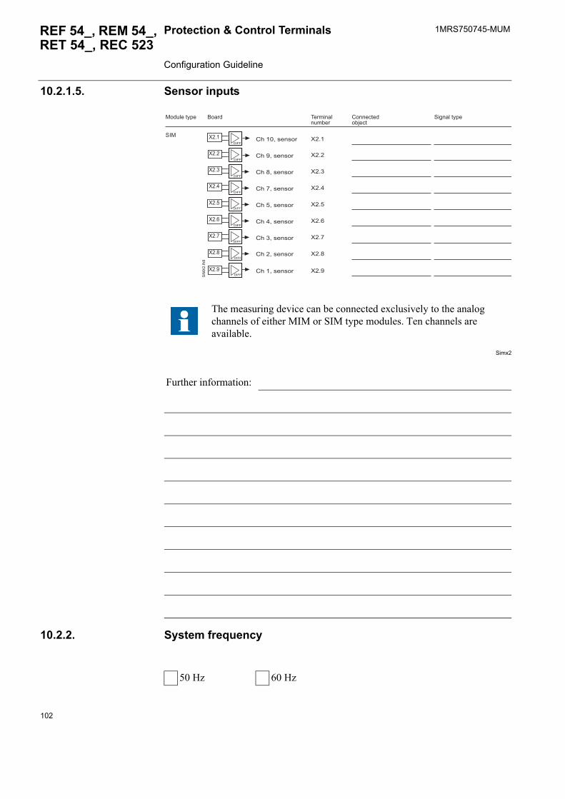
1MRS750745-MUMProtection & Control Terminals Configuration Guideline
REF 54_, REM 54_, RET 54_, REC 523
10.2.1.5. Sensor inputs
Simx2
10.2.2. System frequency
The measuring device can be connected exclusively to the analog channels of either MIM or SIM type modules. Ten channels are available.
Further information:
��
��
�
��
��
��
��
,�--
,�--
,�--
,�--
,�--
,�--
,�--
��,�--'
��
���
�
��,�--
������� �!�"��
�����
'��
���! ��%)*� #����$%���"&�$%
'�(�� �%)*�
#�����.��.��
#������.��.��
#�����.��.��
#�����.��.��
#�����.��.��
#�� ��.��.��
#�����.��.��
#�����.��.��
#�����.��.��
��
��
�
��
��
��
��
��
��
50 Hz 60 Hz
102
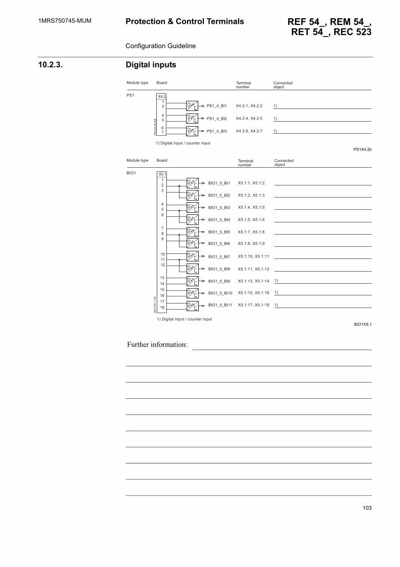
1MRS750745-MUM REF 54_, REM 54_,RET 54_, REC 523
Protection & Control Terminals Configuration Guideline
10.2.3. Digital inputs
PS1X4.2b
BIO1X5.1
Further information:
��
��
��
��
/'
��
�"��
�
������� �!�"��
����� #����$%���"&�$%
��+�����+�
��+�����+�
��+�����+�
/'�
���! ��%)*�
�3�,�(�%� ���*!%�4�$�!�%�����*!%
�3
�3
�3
/'�5�5���
/'�5�5��
/'�5�5���
��
���
���
������
� ����������
��
��6
��
���
�
��+�����+�
��+�����+
��+�����+�
��+�����+�
��+�����+�
��+�����+�
��+������+��
��+������+��
��+� ����+��
��+������+��
��+������+��
�3�,�(�%� ���*!%�4�$�!�%�����*!%
��6�
������� �!�"��
����� #����$%���"&�$%
���! ��%)*�
�3
�3
�3
��6�5�5���
��6�5�5����
��6�5�5���
��6�5�5���
��6�5�5���
��6�5�5���
��6�5�5���
��6�5�5���
��6�5�5��
��6�5�5���
��6�5�5����
103
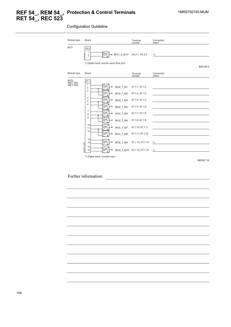
1MRS750745-MUMProtection & Control Terminals Configuration Guideline
REF 54_, REM 54_, RET 54_, REC 523
BIO1X5.2
BIO2X7.1b
Further information:
��
��
��6
��
���
�
��6�
������� �!�"��
����� #����$%���"&�$%
���! ��%)*�
��6�5�5���� ��+�����+� �3
�3�,�(�%� ���*!%4�$�!�%�����*!%4�%����.)�$
��
������
� ��
����
���
���
��
��6
��
�"��
�
��6�012���� 3012�����3
������� �!�"��
����� #����$%���"&�$%
���! ��%)*�
�3�,�(�%� ���*!%�4�$�!�%�����*!%
�3
�3
��6�5�5���
��6�5�5���
��6�5�5���
��6�5�5���
��6�5�5���
��6�5�5���
��6�5�5��
��6�5�5���
��6�5�5����
��6�5�5��� ��+�����+�
��+�����+
��+�����+�
��+�����+�
��+�����+�
��+�����+�
��+������+��
��+������+��
��+� ����+��
��+������+��
104

1MRS750745-MUM REF 54_, REM 54_,RET 54_, REC 523
Protection & Control Terminals Configuration Guideline
10.2.4. Digital outputs
PS1X4.1b
PS1X4.2o_b
Further information:
/'�
������� �!�"��
�����#����$%���"&�$%
���! ��%)*�
/'
��
�"��
�
� 1 -
�#'�
�#'�
��
�
�
��
��
��
��� ��
��
������
�
7
��
�
�
�3
�3
�3
�3
�3�/ ��.������$�%��8��%����%���%��*�$��$!�%�.!*��9�.������*!%.�8� �"��$����(!����%��!.�������%
��+�����+�
/'�5�5:'/6
/'�5�5:'/6�
/'�5�5�#'�
/'�5�5:'/6�
/'�5�5�#'�
/'�5�5���*� ���
/'�5�5�#-��
��+ ����+�����+�
��+�����+����+�����+�
��+������+�����+������+�
��+������+�����+������+��
;����.
/'�
������� �!�"��
�����#����$%���"&�$%
���! ��%)*�
������
� ����
����
��
�
�
��
/'
��
��5"
���
/'�5�5:'/6�
/'�5�5'6�
/'�5�5:'/6���+�����+����+������+��
��+������+� ���+������+��
��+������+�����+��
105

1MRS750745-MUMProtection & Control Terminals Configuration Guideline
REF 54_, REM 54_, RET 54_, REC 523
BIO1X5.2o
BIO2X7.1o_b
Further information:
�
�
��
��
����
��
� ��
��
����
��
��
�
��6
��
����
�
��6�
������� �!�"��
�����#����$%���"&�$%
���! ��%)*�
��6�5�5'6�
��6�5�5'6�
��6�5�5'6
��6�5�5'6�
��6�5�5'6�
��6�5�5'6�
��+ ����+�
��+�����+�
��+�����+�����+�
��+������+������+��
��+� ����+������+��
��+������+������+��
����
����6�012���� 3012�����3
������� �!�"��
�����#����$%���"&�$%
���! ��%)*�
��6�5�5/6���+������+��
106
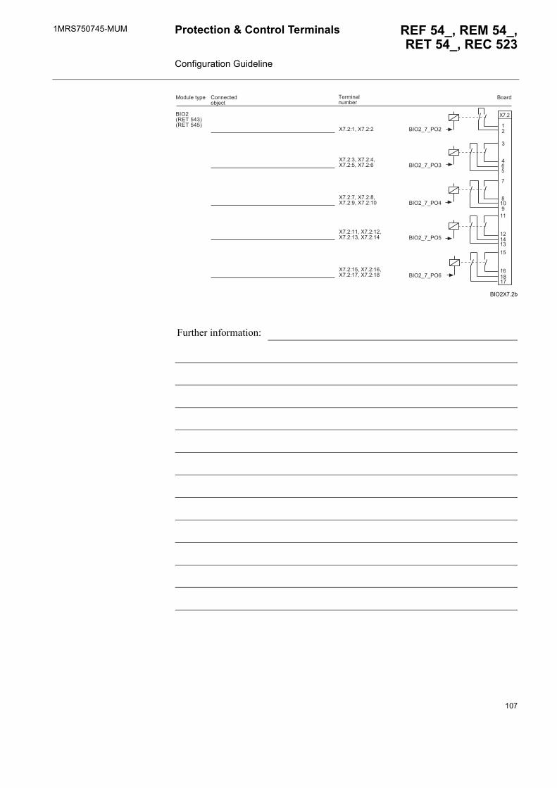
1MRS750745-MUM REF 54_, REM 54_,RET 54_, REC 523
Protection & Control Terminals Configuration Guideline
BIO2X7.2b
Further information:
��
��
�
�
���
��
��
��
��
��
�
����
��6�012���� 3012�����3
������� �!�"��
�����#����$%���"&�$%
���! ��%)*�
����
��6�5�5/6�
��6�5�5/6
��6�5�5/6�
��6�5�5/6�
��6�5�5/6�
��+�����+�
��+ ����+����+�����+�
��+�����+����+�����+��
��+������+�����+� ����+��
��+������+�����+������+��
107

1MRS750745-MUMProtection & Control Terminals Configuration Guideline
REF 54_, REM 54_, RET 54_, REC 523
10.2.5. RTD module
10.2.5.1. RTD/analog inputs
RTD1X6._b
Further information:
1�,�5�5���
1�,�5�5���
1�,�5�5��
1�,�5�5���
1�,�5�5���
1�,�5�5���
1�,�5�5���
1�,�5�5���
1�,�
������� �!�"��
����� #����$%����"&�$%���! ��%)*�
,�--
,�--
,�--
,�--
,�--
��
����
��
��
��
,�--
,�--
,�--
��
���
�� �
��� ��
��
����
��������
;7
;7
;7
;7
':<=�
':<=�
':<=�
':<=�
':<=�
':<=�
':<=�
':<=�
7
;
7
;
7
;
7
;
1�,
��
5"��
�
��+�����+�����+
��+�����+�����+�
��+�����+�����+��
��+������+� ����+��
��+������+������+��
��+�����+�����+
��+�����+�����+�
��+�����+�����+�
�3�#!����%�%���.�!$���4�9� %�(��%���.�!$���4���.�.%��$��.��.��
�3
108
1MRS750745-MUM REF 54_, REM 54_,RET 54_, REC 523
Protection & Control Terminals Configuration Guideline
10.2.5.2. RTD outputs
RTD1X6.2b
10.3. Functionality
10.3.1. Order numberREM54 __ __ __ __ __ __ __ __ __ __
(for example REM543CM212AAAA)
Further information:
��
����
� ��
����
����
��
;7
��
;7
��
;7
��
;7
1�
,�
��"
���
1�,�
������� ��!�"�� ��������! ��%)*� #����$%����"&�$%
1�,�5�5�6�
1�,�5�5�6�
1�,�5�5�6
1�,�5�5�6�
��+������+��
��+� ����+��
��+������+��
��+������+��
109
1MRS750745-MUMProtection & Control Terminals Configuration Guideline
REF 54_, REM 54_, RET 54_, REC 523
10.3.2. Application function blocks used
The lists below represent the full set of function blocks, but the selected functionality level (indicated by a letter in the order number, for example REM543CM212AAAA) determines the function blocks available for the configuration.
ProtectionDEF2Low Inrush3 OPOW6St1 TOL3DevDEF2High MotStart OPOW6St2 UE6LowDEF2Inst NEF1Low OPOW6St3 UE6HighDiff3 NEF1High OV3Low UI6LowDiff6G NEF1Inst OV3High UI6HighDOC6Low NOC3Low PREV3 UPOW6St1DOC6High NOC3High PSV3St1 UPOW6St2DOC6Inst NOC3Inst PSV3St2 UPOW6St3Freq1St1 NPS3Low REF1A UV3LowFreq1St2 NPS3High ROV1Low UV3HighFreq1St3 NUC3St1 ROV1High VOC6LowFreq1St4 NUC3St2 ROV1Inst VOC6HighFreq1St5 OE1Low SCVCSt1FuseFail OE1High SCVCSt2
MeasurementMEAI1 MEAI6 MEAO3 MEDREC16MEAI2 MEAI7 MEAO4 MEFR1MEAI3 MEAI8 MECU1A MEPE7MEAI4 MEAO1 MECU1B MEVO1AMEAI5 MEAO2 MECU3A MEVO3A
ControlCOCB1 CODC5 COLOCAT MMIALAR5COCB2 COIND1 COSW1 MMIALAR6COCBDIR COIND2 COSW2 MMIALAR7CO3DC1 COIND3 COSW3 MMIALAR8CO3DC2 COIND4 COSW4 MMIDATA1CODC1 COIND5 MMIALAR1 MMIDATA2CODC2 COIND6 MMIALAR2 MMIDATA3CODC3 COIND7 MMIALAR3 MMIDATA4CODC4 COIND8 MMIALAR4 MMIDATA5
Condition monitoringCMBWEAR1 CMTCS1CMBWEAR2 CMTCS2
110
1MRS750745-MUM REF 54_, REM 54_,RET 54_, REC 523
Protection & Control Terminals Configuration Guideline
10.3.3. Communication
CMCU3 CMTIME1CMGAS1 CMTIME2CMGAS3 CMTRAV1CMSCHED CMVO3CMSPRC1
CommunicationEVENT230
GeneralINDRESET SWGRP5 SWGRP11 SWGRP17MMIWAKE SWGRP6 SWGRP12 SWGRP18SWGRP1 SWGRP7 SWGRP13 SWGRP19SWGRP2 SWGRP8 SWGRP14 SWGRP20SWGRP3 SWGRP9 SWGRP15SWGRP4 SWGRP10 SWGRP16
Condition monitoring (Continued)
Protocol used: LON SPA Modbus
111
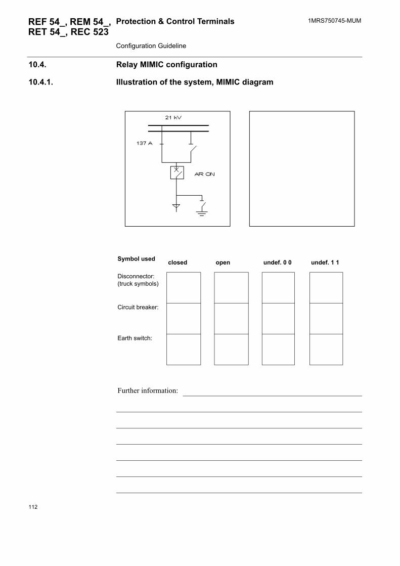
1MRS750745-MUMProtection & Control Terminals Configuration Guideline
REF 54_, REM 54_, RET 54_, REC 523
10.4. Relay MIMIC configuration
10.4.1. Illustration of the system, MIMIC diagram
Symbol used closed open undef. 0 0 undef. 1 1
Disconnector:(truck symbols)
Circuit breaker:
Earth switch:
Further information:
112
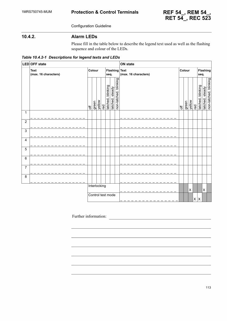
1MRS750745-MUM REF 54_, REM 54_,RET 54_, REC 523
Protection & Control Terminals Configuration Guideline
10.4.2. Alarm LEDsPlease fill in the table below to describe the legend text used as well as the flashing sequence and colour of the LEDs.
Table 10.4.2-1 Descriptions for legend texts and LEDs
LED OFF state ON state
Text(max. 16 characters)
Colour Flashing seq.
Text(max. 16 characters)
Colour Flashing seq.
off
gree
nye
llow
red
latc
hed,
blin
king
latc
hed,
ste
ady
non-
latc
hed,
blin
king
off
gree
nye
llow
red
latc
hed,
blin
king
latc
hed,
ste
ady
non-
latc
hed,
blin
king
1_ _ _ _ _ _ _ _ _ _ _ _ _ _ _ _ _ _ _ _ _ _ _ _ _ _ _ _ _ _ _ _
2_ _ _ _ _ _ _ _ _ _ _ _ _ _ _ _ _ _ _ _ _ _ _ _ _ _ _ _ _ _ _ _
3_ _ _ _ _ _ _ _ _ _ _ _ _ _ _ _ _ _ _ _ _ _ _ _ _ _ _ _ _ _ _ _
4_ _ _ _ _ _ _ _ _ _ _ _ _ _ _ _ _ _ _ _ _ _ _ _ _ _ _ _ _ _ _ _
5_ _ _ _ _ _ _ _ _ _ _ _ _ _ _ _ _ _ _ _ _ _ _ _ _ _ _ _ _ _ _ _
6_ _ _ _ _ _ _ _ _ _ _ _ _ _ _ _ _ _ _ _ _ _ _ _ _ _ _ _ _ _ _ _
7_ _ _ _ _ _ _ _ _ _ _ _ _ _ _ _ _ _ _ _ _ _ _ _ _ _ _ _ _ _ _ _
8_ _ _ _ _ _ _ _ _ _ _ _ _ _ _ _ _ _ _ _ _ _ _ _ _ _ _ _ _ _ _ _
Interlocking_ _ _ _ _ _ _ _ _ _ _ _ _ _ _ _ X X
Control test mode_ _ _ _ _ _ _ _ _ _ _ _ _ _ _ _ X X
Further information:
113
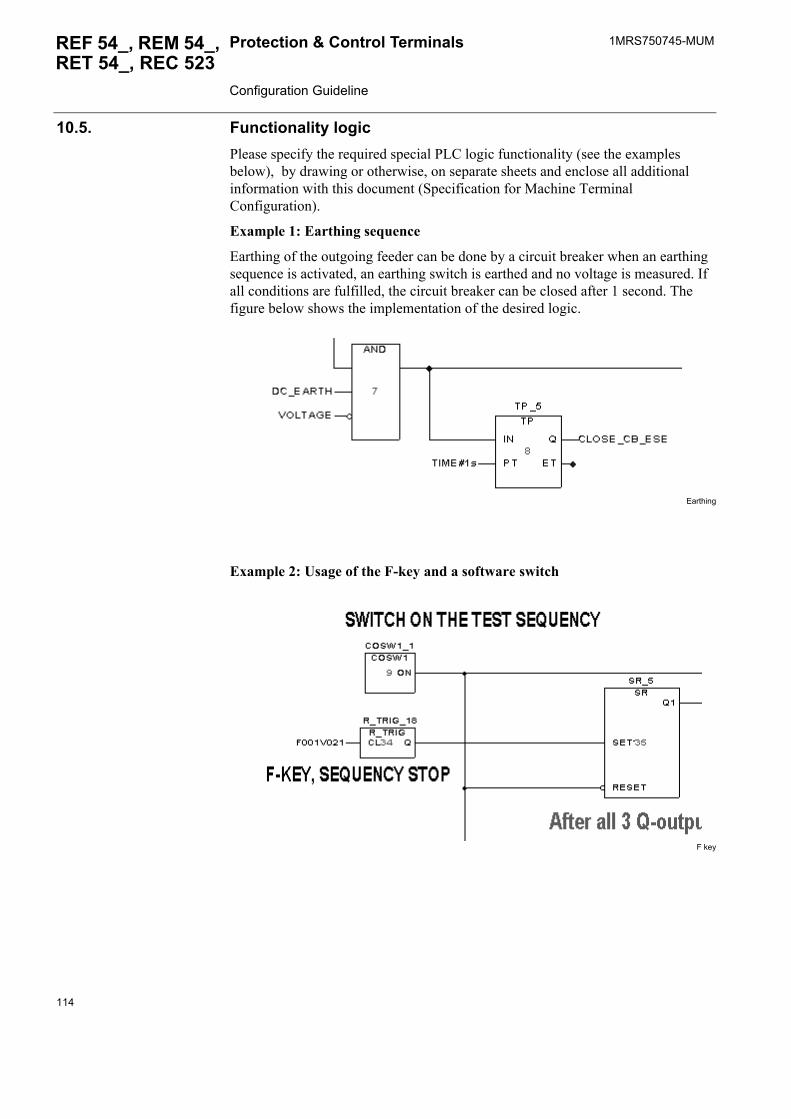
1MRS750745-MUMProtection & Control Terminals Configuration Guideline
REF 54_, REM 54_, RET 54_, REC 523
10.5. Functionality logicPlease specify the required special PLC logic functionality (see the examples below), by drawing or otherwise, on separate sheets and enclose all additional information with this document (Specification for Machine Terminal Configuration).
Example 1: Earthing sequence
Earthing of the outgoing feeder can be done by a circuit breaker when an earthing sequence is activated, an earthing switch is earthed and no voltage is measured. If all conditions are fulfilled, the circuit breaker can be closed after 1 second. The figure below shows the implementation of the desired logic.
Earthing
Example 2: Usage of the F-key and a software switch
F key
114
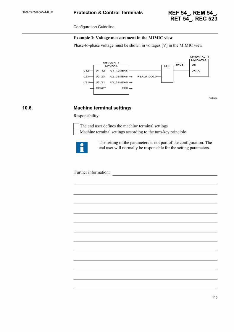
1MRS750745-MUM REF 54_, REM 54_,RET 54_, REC 523
Protection & Control Terminals Configuration Guideline
Example 3: Voltage measurement in the MIMIC view
Phase-to-phase voltage must be shown in voltages [V] in the MIMIC view.
Voltage
10.6. Machine terminal settingsResponsibility:
The end user defines the machine terminal settingsMachine terminal settings according to the turn-key principle
The setting of the parameters is not part of the configuration. The end user will normally be responsible for the setting parameters.
Further information:
115

116
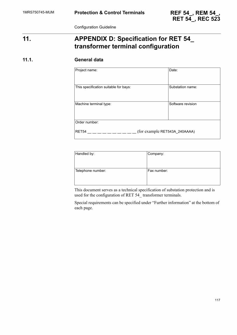
1MRS750745-MUM REF 54_, REM 54_,RET 54_, REC 523
Protection & Control Terminals Configuration Guideline
11. APPENDIX D: Specification for RET 54_ transformer terminal configuration
11.1. General data
This document serves as a technical specification of substation protection and is used for the configuration of RET 54_ transformer terminals.
Special requirements can be specified under �Further information� at the bottom of each page.
Project name: Date:
This specification suitable for bays: Substation name:
Machine terminal type: Software revision
Order number:
RET54 __ __ __ __ __ __ __ __ __ __ (for example RET543A_240AAAA)
Handled by: Company:
Telephone number: Fax number:
117
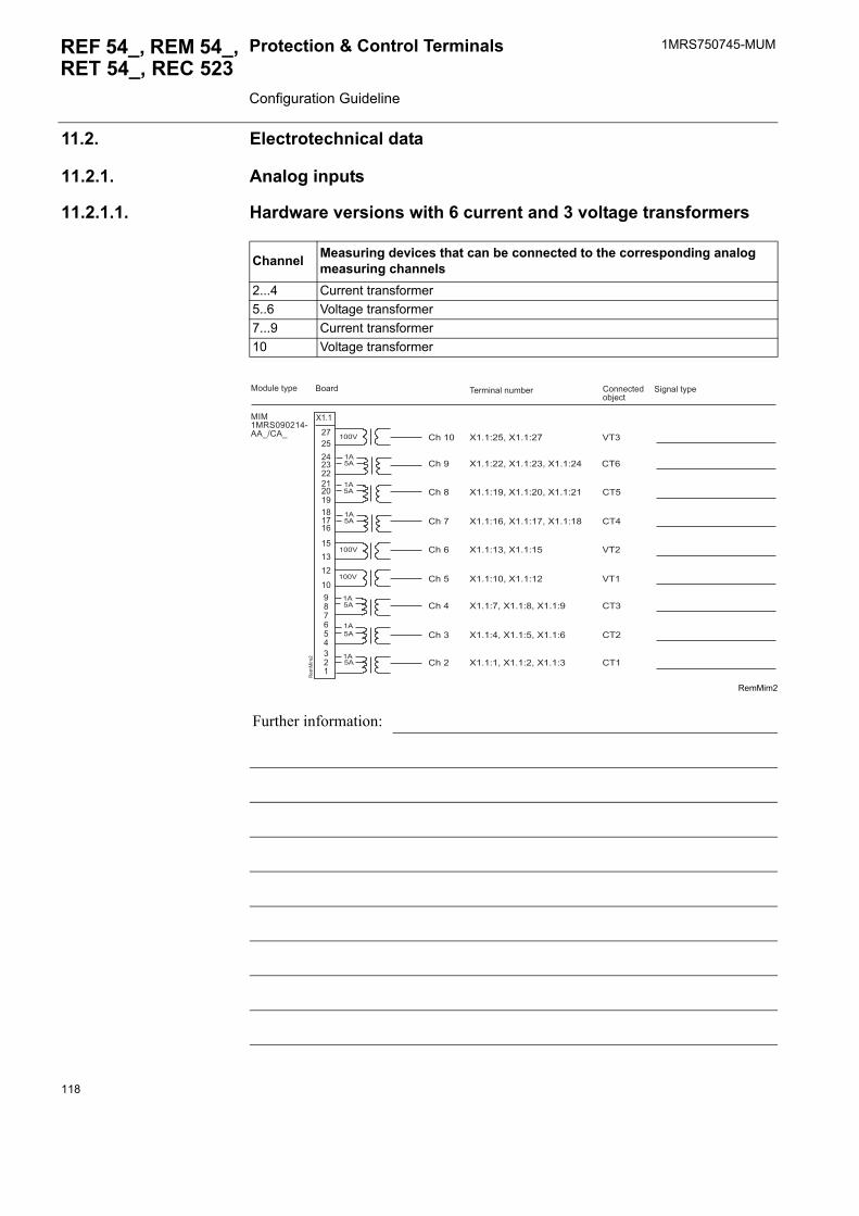
1MRS750745-MUMProtection & Control Terminals Configuration Guideline
REF 54_, REM 54_, RET 54_, REC 523
11.2. Electrotechnical data
11.2.1. Analog inputs
11.2.1.1. Hardware versions with 6 current and 3 voltage transformers
RemMim2
Channel Measuring devices that can be connected to the corresponding analog measuring channels
2...4 Current transformer5..6 Voltage transformer7...9 Current transformer10 Voltage transformer
Further information:
�����1'������7��54#�5
������� ��!�"������� #����$%���"&�$%
���! ��%)*� '�(�� �%)*�
����
����
����
����
����
����
����
����
����
��
1��
���
�
����
��
����
����
��
��
�
��
�������� ��
�
��
��
#���
#���
#���
#���
#����
#���
#��
#���
#���
���
#��
#��
#��
��
#��
#��
#�
���
��+������+��
��+������+� ����+��
��+������+������+��
��+������+������+��
��+� ����+��
��+������+��
��+�����+�����+�
��+�����+�����+�
��+�����+�����+
118
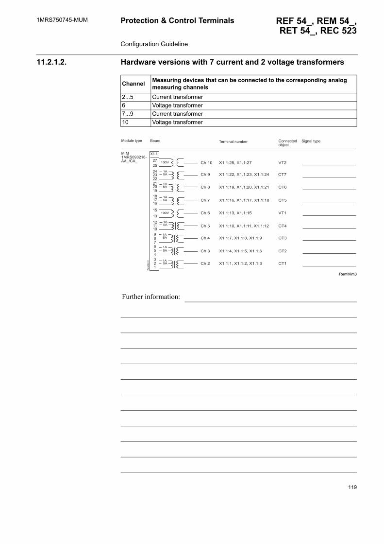
1MRS750745-MUM REF 54_, REM 54_,RET 54_, REC 523
Protection & Control Terminals Configuration Guideline
11.2.1.2. Hardware versions with 7 current and 2 voltage transformers
RemMim3
Channel Measuring devices that can be connected to the corresponding analog measuring channels
2...5 Current transformer6 Voltage transformer 7...9 Current transformer10 Voltage transformer
Further information:
�����1'������7��54#�5
������� ��!�"������� #����$%���"&�$%
���! ��%)*� '�(�� �%)*�
����
����
����
����
����
����
����
����
����
��
1��
���
����
��
����
����
��
��
�
��
�������� ��
�
��
��
��
#���
#���
#���
#���
#����
#���
#��
#���
#���
���
#��
#��
#��
���
#��
#��
#�
#��
��+������+��
��+������+� ����+��
��+������+������+��
��+������+������+��
��+� ����+��
��+������+������+��
��+�����+�����+�
��+�����+�����+�
��+�����+�����+
119
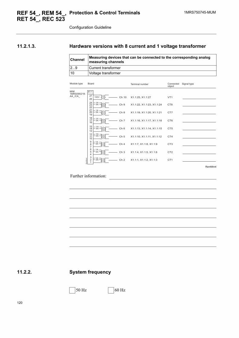
1MRS750745-MUMProtection & Control Terminals Configuration Guideline
REF 54_, REM 54_, RET 54_, REC 523
11.2.1.3. Hardware versions with 8 current and 1 voltage transformer
RemMim4
11.2.2. System frequency
Channel Measuring devices that can be connected to the corresponding analog measuring channels
2...9 Current transformer10 Voltage transformer
Further information:
�����1'������7��54#�5
������� ��!�"������� #����$%���"&�$%
���! ��%)*� '�(�� �%)*�
����
����
����
����
����
����
����
����
����
��
1��
���
�
����
��
����
����
��
��
� ��
�������� ��
�
��
��
��
�� #���
#���
#���
#���
#����
#���
#��
#���
#���
#��
#��
#��
#��
���
#��
#��
#�
#��
��+������+��
��+������+� ����+��
��+������+������+��
��+������+������+��
��+� ����+������+��
��+������+������+��
��+�����+�����+�
��+�����+�����+�
��+�����+�����+
50 Hz 60 Hz
120

1MRS750745-MUM REF 54_, REM 54_,RET 54_, REC 523
Protection & Control Terminals Configuration Guideline
11.2.3. Digital inputs
PS1X4.2b
BIO1X5.1
Further information:
��
��
��
��
/'
��
�"��
�
������� �!�"��
����� #����$%���"&�$%
��+�����+�
��+�����+�
��+�����+�
/'�
���! ��%)*�
�3�,�(�%� ���*!%�4�$�!�%�����*!%
�3
�3
�3
/'�5�5���
/'�5�5��
/'�5�5���
��
���
���
������
� ����������
��
��6
��
���
�
��+�����+�
��+�����+
��+�����+�
��+�����+�
��+�����+�
��+�����+�
��+������+��
��+������+��
��+� ����+��
��+������+��
��+������+��
�3�,�(�%� ���*!%�4�$�!�%�����*!%
��6�
������� �!�"��
����� #����$%���"&�$%
���! ��%)*�
�3
�3
�3
��6�5�5���
��6�5�5����
��6�5�5���
��6�5�5���
��6�5�5���
��6�5�5���
��6�5�5���
��6�5�5���
��6�5�5��
��6�5�5���
��6�5�5����
121

1MRS750745-MUMProtection & Control Terminals Configuration Guideline
REF 54_, REM 54_, RET 54_, REC 523
BIO1X5.2
A050028
Further information:
��
��
��6
��
���
�
��6�
������� �!�"��
����� #����$%���"&�$%
���! ��%)*�
��6�5�5���� ��+�����+� �3
�3�,�(�%� ���*!%4�$�!�%�����*!%4�%����.)�$
��
������
� ��
����
���
���
��
��6
��
�"��
�
��6�012���� 3012�����3
������� �!�"��
����� #����$%���"&�$%
���! ��%)*�
�3�,�(�%� ���*!%�4�$�!�%�����*!%
�3
�3
��6�5�5���
��6�5�5���
��6�5�5���
��6�5�5���
��6�5�5���
��6�5�5���
��6�5�5��
��6�5�5���
��6�5�5����
��6�5�5��� ��+�����+�
��+�����+
��+�����+�
��+�����+�
��+�����+�
��+�����+�
��+������+��
��+������+��
��+� ����+��
��+������+��
122
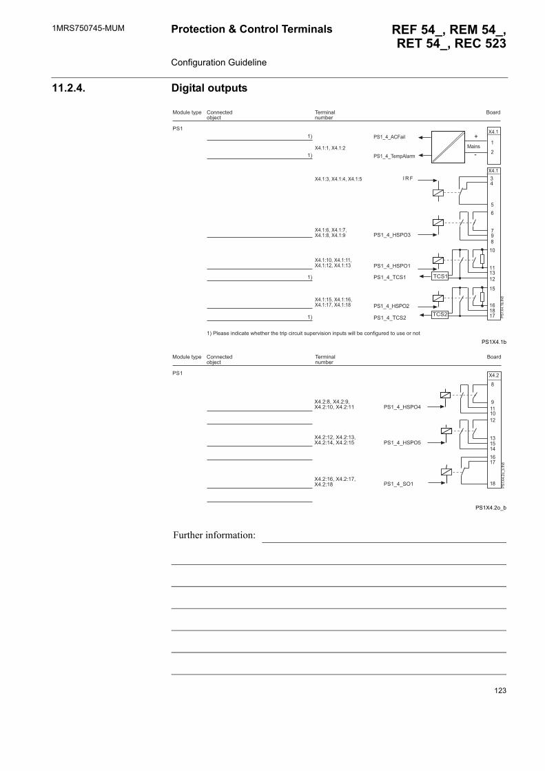
1MRS750745-MUM REF 54_, REM 54_,RET 54_, REC 523
Protection & Control Terminals Configuration Guideline
11.2.4. Digital outputs
PS1X4.1b
PS1X4.2o_b
Further information:
/'�
������� �!�"��
�����#����$%���"&�$%
���! ��%)*�
/'
��
�"��
�
� 1 -
�#'�
�#'�
��
�
�
��
��
��
��� ��
��
������
�
7
��
�
�
�3
�3
�3
�3
�3�/ ��.������$�%��8��%����%���%��*�$��$!�%�.!*��9�.������*!%.�8� �"��$����(!����%��!.�������%
��+�����+�
/'�5�5:'/6
/'�5�5:'/6�
/'�5�5�#'�
/'�5�5:'/6�
/'�5�5�#'�
/'�5�5���*� ���
/'�5�5�#-��
��+ ����+�����+�
��+�����+����+�����+�
��+������+�����+������+�
��+������+�����+������+��
;����.
/'�
������� �!�"��
�����#����$%���"&�$%
���! ��%)*�
������
� ����
����
��
�
�
��
/'
��
��5"
���
/'�5�5:'/6�
/'�5�5'6�
/'�5�5:'/6���+�����+����+������+��
��+������+� ���+������+��
��+������+�����+��
123
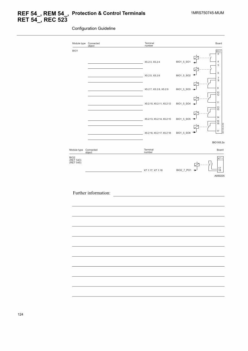
1MRS750745-MUMProtection & Control Terminals Configuration Guideline
REF 54_, REM 54_, RET 54_, REC 523
BIO1X5.2o
A050225
�
�
��
��
����
��
� ��
��
����
��
��
�
��6
��
����
�
��6�
������� �!�"��
�����#����$%���"&�$%
���! ��%)*�
��6�5�5'6�
��6�5�5'6�
��6�5�5'6
��6�5�5'6�
��6�5�5'6�
��6�5�5'6�
��+ ����+�
��+�����+�
��+�����+�����+�
��+������+������+��
��+� ����+������+��
��+������+������+��
����
����6�012���� 3012�����3
������� �!�"��
�����#����$%���"&�$%
���! ��%)*�
��6�5�5/6���+������+��
Further information:
124
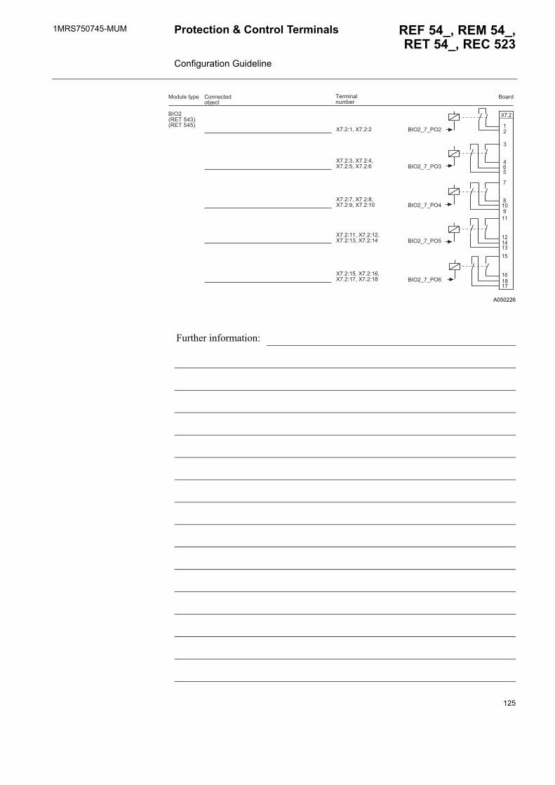
1MRS750745-MUM REF 54_, REM 54_,RET 54_, REC 523
Protection & Control Terminals Configuration Guideline
A050226
��
��
�
�
���
��
��
��
��
��
�
����
��6�012���� 3012�����3
������� �!�"��
�����#����$%���"&�$%
���! ��%)*�
����
��6�5�5/6�
��6�5�5/6
��6�5�5/6�
��6�5�5/6�
��6�5�5/6�
��+�����+�
��+ ����+����+�����+�
��+�����+����+�����+��
��+������+�����+� ����+��
��+������+�����+������+��
Further information:
125
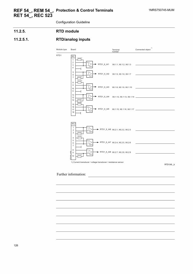
1MRS750745-MUMProtection & Control Terminals Configuration Guideline
REF 54_, REM 54_, RET 54_, REC 523
11.2.5. RTD module
11.2.5.1. RTD/analog inputs
RTD1X6._b
Further information:
1�,�5�5���
1�,�5�5���
1�,�5�5��
1�,�5�5���
1�,�5�5���
1�,�5�5���
1�,�5�5���
1�,�5�5���
1�,�
������� �!�"��
����� #����$%����"&�$%���! ��%)*�
,�--
,�--
,�--
,�--
,�--
��
����
��
��
��
,�--
,�--
,�--
��
���
�� �
��� ��
��
����
��������
;7
;7
;7
;7
':<=�
':<=�
':<=�
':<=�
':<=�
':<=�
':<=�
':<=�
7
;
7
;
7
;
7
;
1�,
��
5"��
�
��+�����+�����+
��+�����+�����+�
��+�����+�����+��
��+������+� ����+��
��+������+������+��
��+�����+�����+
��+�����+�����+�
��+�����+�����+�
�3�#!����%�%���.�!$���4�9� %�(��%���.�!$���4���.�.%��$��.��.��
�3
126
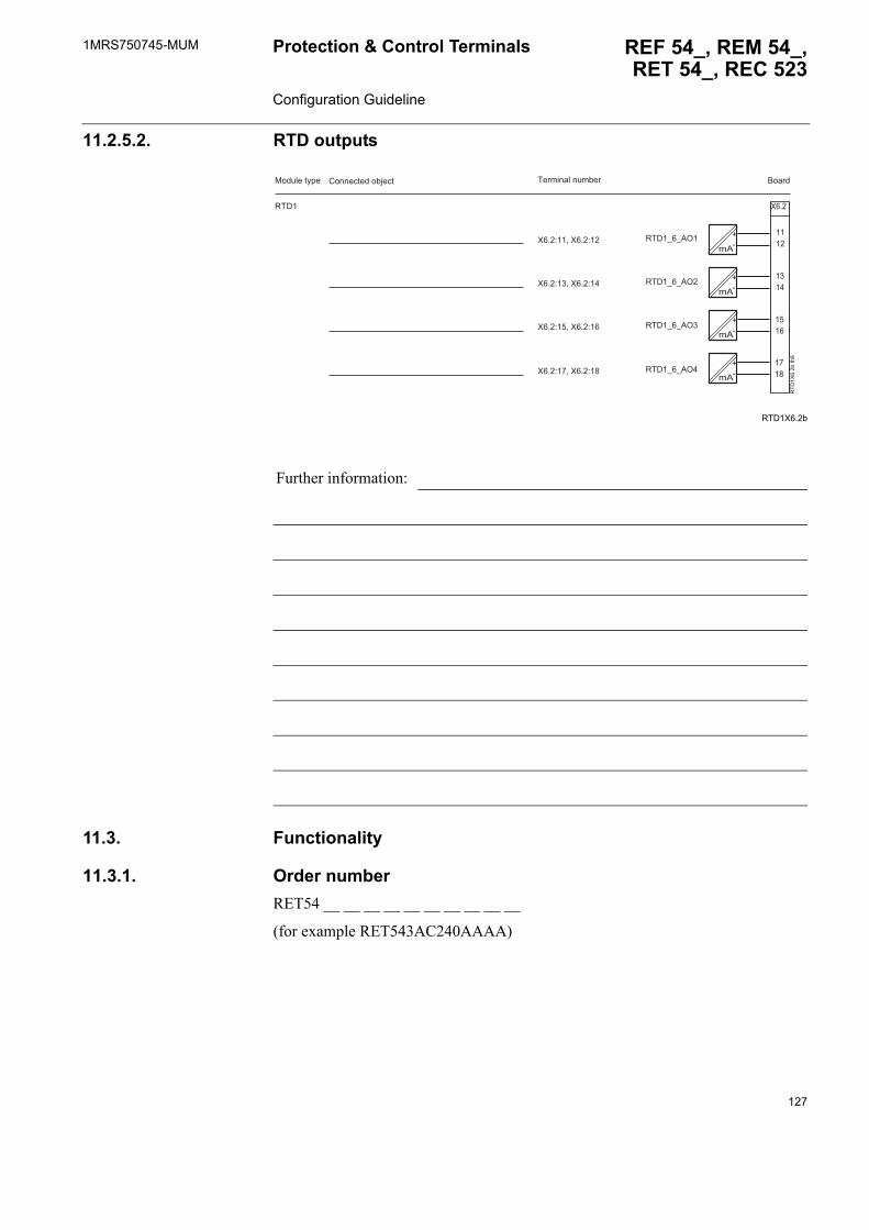
1MRS750745-MUM REF 54_, REM 54_,RET 54_, REC 523
Protection & Control Terminals Configuration Guideline
11.2.5.2. RTD outputs
RTD1X6.2b
11.3. Functionality
11.3.1. Order numberRET54 __ __ __ __ __ __ __ __ __ __
(for example RET543AC240AAAA)
Further information:
��
����
� ��
����
����
��
;7
��
;7
��
;7
��
;7
1�
,�
��"
���
1�,�
������� ��!�"�� ��������! ��%)*� #����$%����"&�$%
1�,�5�5�6�
1�,�5�5�6�
1�,�5�5�6
1�,�5�5�6�
��+������+��
��+� ����+��
��+������+��
��+������+��
127
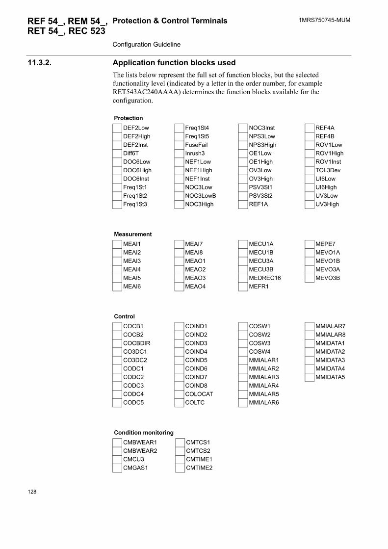
1MRS750745-MUMProtection & Control Terminals Configuration Guideline
REF 54_, REM 54_, RET 54_, REC 523
11.3.2. Application function blocks usedThe lists below represent the full set of function blocks, but the selected functionality level (indicated by a letter in the order number, for example RET543AC240AAAA) determines the function blocks available for the configuration.
ProtectionDEF2Low Freq1St4 NOC3Inst REF4ADEF2High Freq1St5 NPS3Low REF4BDEF2Inst FuseFail NPS3High ROV1LowDiff6T Inrush3 OE1Low ROV1HighDOC6Low NEF1Low OE1High ROV1InstDOC6High NEF1High OV3Low TOL3DevDOC6Inst NEF1Inst OV3High UI6LowFreq1St1 NOC3Low PSV3St1 UI6HighFreq1St2 NOC3LowB PSV3St2 UV3LowFreq1St3 NOC3High REF1A UV3High
MeasurementMEAI1 MEAI7 MECU1A MEPE7MEAI2 MEAI8 MECU1B MEVO1AMEAI3 MEAO1 MECU3A MEVO1BMEAI4 MEAO2 MECU3B MEVO3AMEAI5 MEAO3 MEDREC16 MEVO3BMEAI6 MEAO4 MEFR1
ControlCOCB1 COIND1 COSW1 MMIALAR7COCB2 COIND2 COSW2 MMIALAR8COCBDIR COIND3 COSW3 MMIDATA1CO3DC1 COIND4 COSW4 MMIDATA2CO3DC2 COIND5 MMIALAR1 MMIDATA3CODC1 COIND6 MMIALAR2 MMIDATA4CODC2 COIND7 MMIALAR3 MMIDATA5CODC3 COIND8 MMIALAR4CODC4 COLOCAT MMIALAR5CODC5 COLTC MMIALAR6
Condition monitoringCMBWEAR1 CMTCS1CMBWEAR2 CMTCS2CMCU3 CMTIME1CMGAS1 CMTIME2
128
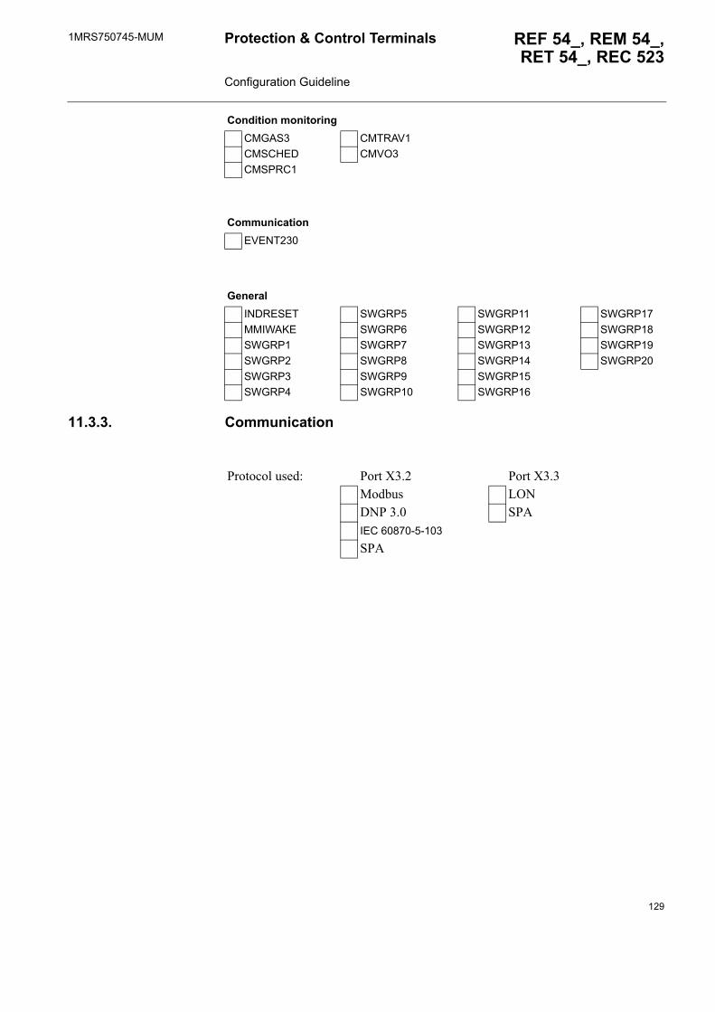
1MRS750745-MUM REF 54_, REM 54_,RET 54_, REC 523
Protection & Control Terminals Configuration Guideline
11.3.3. Communication
CMGAS3 CMTRAV1CMSCHED CMVO3CMSPRC1
CommunicationEVENT230
GeneralINDRESET SWGRP5 SWGRP11 SWGRP17MMIWAKE SWGRP6 SWGRP12 SWGRP18SWGRP1 SWGRP7 SWGRP13 SWGRP19SWGRP2 SWGRP8 SWGRP14 SWGRP20SWGRP3 SWGRP9 SWGRP15SWGRP4 SWGRP10 SWGRP16
Condition monitoring
Protocol used: Port X3.2 Port X3.3Modbus LONDNP 3.0 SPAIEC 60870-5-103
SPA
129
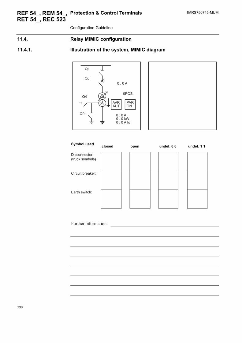
1MRS750745-MUMProtection & Control Terminals Configuration Guideline
REF 54_, REM 54_, RET 54_, REC 523
11.4. Relay MIMIC configuration
11.4.1. Illustration of the system, MIMIC diagram
Symbol used closed open undef. 0 0 undef. 1 1
Disconnector:(truck symbols)
Circuit breaker:
Earth switch:
Further information:
>�
>�
>�
>�
��1�<�
/�16=
������
�����������?@���������
�/6'
130

1MRS750745-MUM REF 54_, REM 54_,RET 54_, REC 523
Protection & Control Terminals Configuration Guideline
11.4.2. Alarm LEDsPlease fill in the table below to describe the legend text used as well as the flashing sequence and colour of the LEDs.
Table 11.4.2-1 Descriptions for legend texts and LEDs
LED OFF state ON state
Text(max. 16 characters)
Colour Flashing seq.
Text(max. 16 characters)
Colour Flashing seq.
off
gree
nye
llow
red
latc
hed,
blin
king
latc
hed,
ste
ady
non-
latc
hed,
blin
king
off
gree
nye
llow
red
latc
hed,
blin
king
latc
hed,
ste
ady
non-
latc
hed,
blin
king
1_ _ _ _ _ _ _ _ _ _ _ _ _ _ _ _ _ _ _ _ _ _ _ _ _ _ _ _ _ _ _ _
2_ _ _ _ _ _ _ _ _ _ _ _ _ _ _ _ _ _ _ _ _ _ _ _ _ _ _ _ _ _ _ _
3_ _ _ _ _ _ _ _ _ _ _ _ _ _ _ _ _ _ _ _ _ _ _ _ _ _ _ _ _ _ _ _
4_ _ _ _ _ _ _ _ _ _ _ _ _ _ _ _ _ _ _ _ _ _ _ _ _ _ _ _ _ _ _ _
5_ _ _ _ _ _ _ _ _ _ _ _ _ _ _ _ _ _ _ _ _ _ _ _ _ _ _ _ _ _ _ _
6_ _ _ _ _ _ _ _ _ _ _ _ _ _ _ _ _ _ _ _ _ _ _ _ _ _ _ _ _ _ _ _
7_ _ _ _ _ _ _ _ _ _ _ _ _ _ _ _ _ _ _ _ _ _ _ _ _ _ _ _ _ _ _ _
8_ _ _ _ _ _ _ _ _ _ _ _ _ _ _ _ _ _ _ _ _ _ _ _ _ _ _ _ _ _ _ _
Interlocking_ _ _ _ _ _ _ _ _ _ _ _ _ _ _ _ X X
Control test mode_ _ _ _ _ _ _ _ _ _ _ _ _ _ _ _ X X
Further information:
131
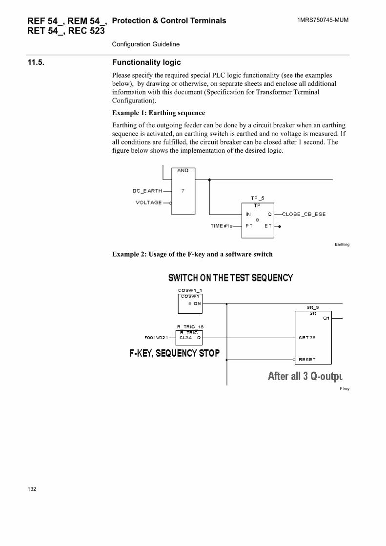
1MRS750745-MUMProtection & Control Terminals Configuration Guideline
REF 54_, REM 54_, RET 54_, REC 523
11.5. Functionality logicPlease specify the required special PLC logic functionality (see the examples below), by drawing or otherwise, on separate sheets and enclose all additional information with this document (Specification for Transformer Terminal Configuration).
Example 1: Earthing sequence
Earthing of the outgoing feeder can be done by a circuit breaker when an earthing sequence is activated, an earthing switch is earthed and no voltage is measured. If all conditions are fulfilled, the circuit breaker can be closed after 1 second. The figure below shows the implementation of the desired logic.
Earthing
Example 2: Usage of the F-key and a software switch
F key
132
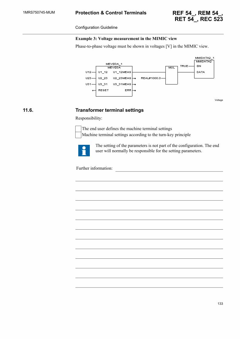
1MRS750745-MUM REF 54_, REM 54_,RET 54_, REC 523
Protection & Control Terminals Configuration Guideline
Example 3: Voltage measurement in the MIMIC view
Phase-to-phase voltage must be shown in voltages [V] in the MIMIC view.
Voltage
11.6. Transformer terminal settingsResponsibility:
The end user defines the machine terminal settingsMachine terminal settings according to the turn-key principle
The setting of the parameters is not part of the configuration. The end user will normally be responsible for the setting parameters.
Further information:
133

134
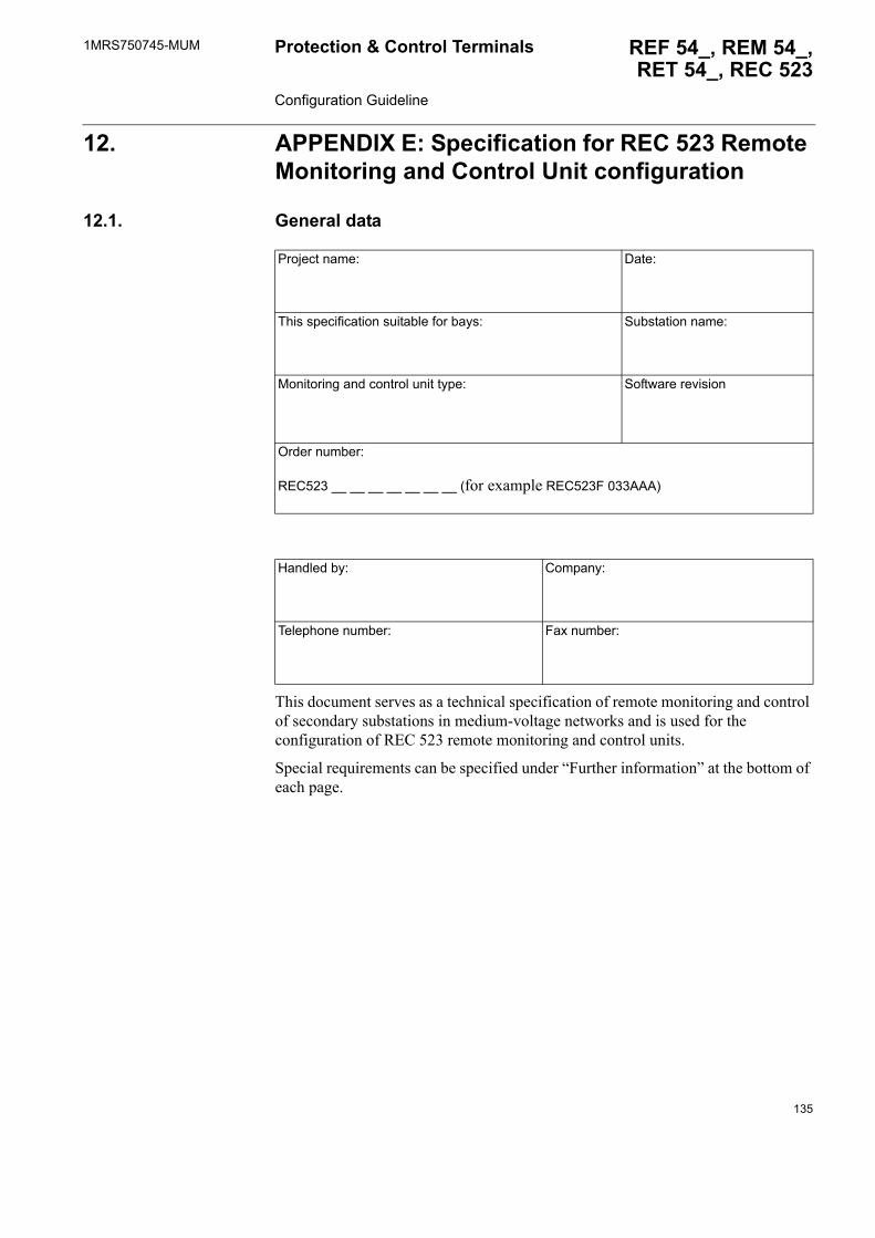
1MRS750745-MUM REF 54_, REM 54_,RET 54_, REC 523
Protection & Control Terminals Configuration Guideline
12. APPENDIX E: Specification for REC 523 Remote Monitoring and Control Unit configuration
12.1. General data
This document serves as a technical specification of remote monitoring and control of secondary substations in medium-voltage networks and is used for the configuration of REC 523 remote monitoring and control units.
Special requirements can be specified under �Further information� at the bottom of each page.
Project name: Date:
This specification suitable for bays: Substation name:
Monitoring and control unit type: Software revision
Order number:
REC523 __ __ __ __ __ __ __ (for example REC523F 033AAA)
Handled by: Company:
Telephone number: Fax number:
135
1MRS750745-MUMProtection & Control Terminals Configuration Guideline
REF 54_, REM 54_, RET 54_, REC 523
12.2. Electrotechnical data
12.2.1. Analog inputs
Table 12.2.-1 Analog input channel connections
Channel Measuring devices that can be connected to the corresponding analog measuring channels
1 Rogowski sensor, voltage divider or general measurement2...4 Current transformer, Rogowski sensor, voltage divider, or general
measurement5, 7...9 Voltage transfomer,current transformer, Rogowski sensor, voltage divider or
general measurement6 Voltage transformer or general measururement10 Voltage transformer, Rogowski sensor, voltage divider or
general measurement
Further information:
136
1MRS750745-MUM REF 54_, REM 54_,RET 54_, REC 523
Protection & Control Terminals Configuration Guideline
RecMim1
RecMim2
Further information:
���0� ��5���� ��5��3
������� ��!�"������� #����$%���"&�$%
���! ��%)*� '�(�� �%)*�
����
����
��
1�$
���
�
������ ��
����
#���
#��
#���
#��
#��
#� ��+�����+�����+�
��+�����+�����+�
��+�����+�����+
���0� �5���� ��5��3
������� ��!�"������� #����$%���"&�$%
���! ��%)*� '�(�� �%)*�
����
����
����
����
����
��
1�$
���
�
����
��
��
��
��
��
����
� ��
�������� ��
����
��
#���
#���
#����
#���
#��
#���
���
���
��
#��
#��
#�
��+������+��
��+������+��
��+������+��
��+�����+�����+�
��+�����+�����+�
��+�����+�����+
137
1MRS750745-MUMProtection & Control Terminals Configuration Guideline
REF 54_, REM 54_, RET 54_, REC 523
RecMim3
RecMim4
Further information:
���0� ��5���� ��5��3
������� ��!�"������� #����$%���"&�$%
���! ��%)*� '�(�� �%)*�
� ��
� ��
� ��
����
����
��
1�$
���
����
��
��
��
��
��
����
� ��
�������� ��
����
������
#���
#���
#����
#���
#��
#���
#���
���
���
��
#��
#��
#�
#��
��+������+��
��+������+��
��+������+��
��+������+������+��
��+�����+�����+�
��+�����+�����+�
��+�����+�����+
���0����5�������5��3
������� ��!�"������� #����$%���"&�$%
���! ��%)*� '�(�� �%)*�
����
����
����
����
����
����
����
����
����
��
1�$
���
�
����
��
����
����
��
��
�
��
�������� ��
�
��
��
#���
#���
#���
#���
#����
#���
#��
#���
#���
���
#��
#��
#��
��
#��
#��
#�
���
��+������+��
��+������+� ����+��
��+������+������+��
��+������+������+��
��+� ����+��
��+������+��
��+�����+�����+�
��+�����+�����+�
��+�����+�����+
138
1MRS750745-MUM REF 54_, REM 54_,RET 54_, REC 523
Protection & Control Terminals Configuration Guideline
RecMim5
A050027
Further information:
���0����5�������5��3
������� ��!�"������� #����$%���"&�$%
���! ��%)*� '�(�� �%)*�
����
����
����
����
����
����
��
1�$
���
�
����
��
��
��
��
��
����
� ��
�������� ��
����
����
����
#���
#���
#���
#���
#����
#���
#��
#���
#���
���
��
���
���
���
#��
#��
#�
���
��+������+��
��+������+��
��+������+��
��+������+��
��+� ����+��
��+������+��
��+�����+�����+�
��+�����+�����+�
��+�����+�����+
��+�������+��
��+�������+��
��+�������+��
��+�������+��
��+� ����+������+��
��+�������+��
��+������+������+�
��+������+������+�
��+������+������+
����� ��
�
����
������
����
����
����
����
����
����
����
���
��
���
���
#��
#��
#�
#��
#��
���0���5������5��
���! �%)*�
����� ������� ��!�"�� #����$%���"&�$%
'�(�� �%)*�
#���
#��
#���
#���
��
#���
#���
#���
#���
#����
����
� ��
������
� ����
��
����
��
��
139
1MRS750745-MUMProtection & Control Terminals Configuration Guideline
REF 54_, REM 54_, RET 54_, REC 523
Simx2
12.2.1. System frequency
The measuring device can be connected exclusively to the analog channels of either MIM or SIM type modules.
Further information:
��
��
�
��
��
��
��
,�--
,�--
,�--
,�--
,�--
,�--
,�--
��,�--'
��
���
�
��,�--
������� �!�"��
�����
'��
���! ��%)*� #����$%���"&�$%
'�(�� �%)*�
#�����.��.��
#������.��.��
#�����.��.��
#�����.��.��
#�����.��.��
#�� ��.��.��
#�����.��.��
#�����.��.��
#�����.��.��
��
��
�
��
��
��
��
��
��
50 Hz 60 Hz
140
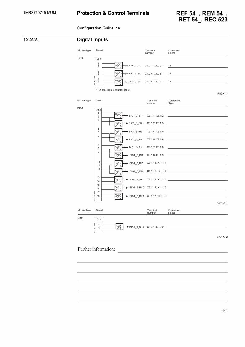
1MRS750745-MUM REF 54_, REM 54_,RET 54_, REC 523
Protection & Control Terminals Configuration Guideline
12.2.2. Digital inputs
PSCX7.3
BIO1X3.1
BIO1X3.2
Further information:
������� �!�"��
����� #����$%���"&�$%
/'#
���! ��%)*�
/'#5�5���
/'#5�5���
/'#5�5��
�
��
�
��
��+�����+�
��+�����+�
��+�����+�
�3�,�(�%� ���*!%�4�$�!�%�����*!%
�3
�3
�3
/'
#
�
���
��6�5 5���
��6�5 5���
��6�5 5���
��6�5 5����
��6�5 5����
��6�5 5���
��6�5 5���
��6�5 5��
��6�5 5���
��6�5 5���
��6�5 5���
������� �!�"��
����� #����$%���"&�$%
��6�
���! ��%)*�
�+��� �+�
�+��� �+
�+��� �+�
�+��� �+�
�+��� �+�
�+��� �+�
�+���� �+��
�+���� �+��
�+� �� �+��
�+���� �+��
�+���� �+��
��6
�
���
�
��
���
���
������
�
��
��
��
��
��
�
��6�5 5����
������� �!�"��
����� #����$%���"&�$%
��6�
���! ��%)*�
��6
�
���
�
�+��� �+���
�
141
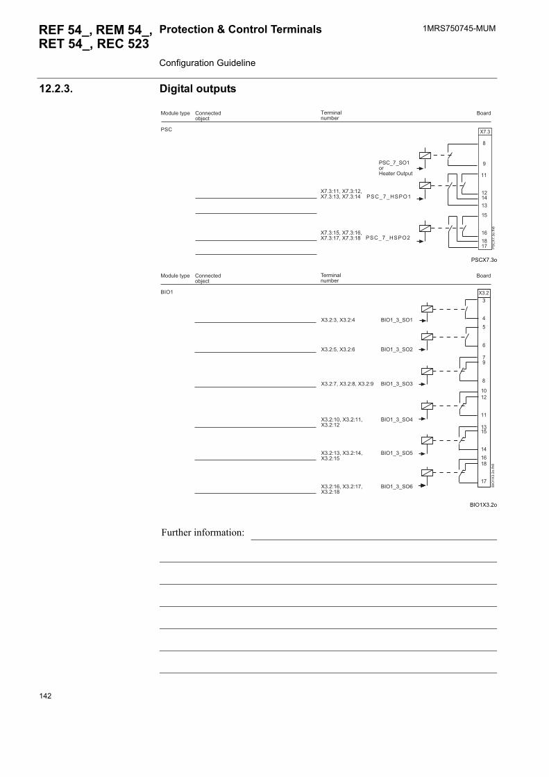
1MRS750745-MUMProtection & Control Terminals Configuration Guideline
REF 54_, REM 54_, RET 54_, REC 523
12.2.3. Digital outputs
PSCX7.3o
BIO1X3.2o
Further information:
�
����
��
�����
��
��
��
�
/'#5�5'6���:��%���6!%*!%
/ ' # 5 � 5 : ' / 6 �
/ ' # 5 � 5 : ' / 6 �
/'#
������� �!�"��
�����#����$%���"&�$%
���! ��%)*�
/'
#
� �
���
� +����� +���� +� ��� +��
� +����� +���� +����� +��
�
�
��
��
����
��
� ��
��
����
��
�
���6�5 5'6�
��6�5 5'6�
��6�5 5'6
��6�5 5'6�
��6�5 5'6�
��6�5 5'6�
��6�
������� �!�"��
�����#����$%���"&�$%
���! ��%)*�
��6
�
����
�
�+ �� �+�
�+��� �+�
�+��� �+��� �+�
�+���� �+��� �+��
�+� �� �+��� �+��
�+���� �+��� �+��
142
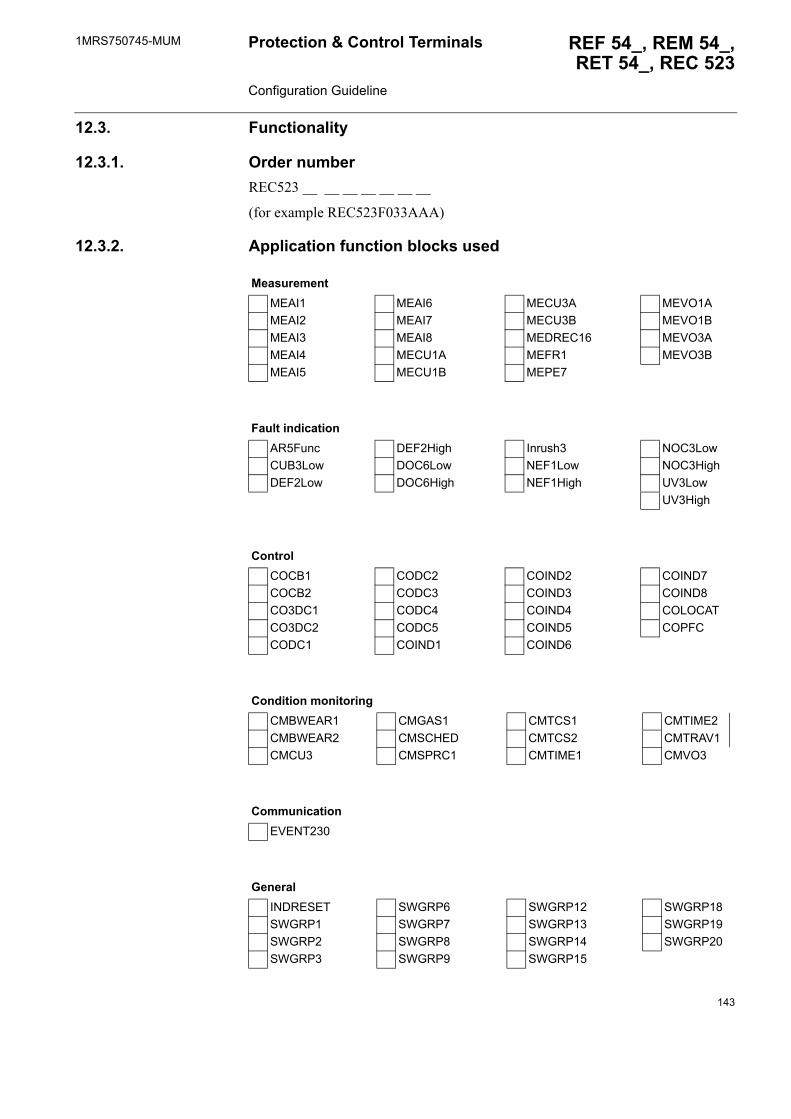
1MRS750745-MUM REF 54_, REM 54_,RET 54_, REC 523
Protection & Control Terminals Configuration Guideline
12.3. Functionality
12.3.1. Order numberREC523 __ __ __ __ __ __ __
(for example REC523F033AAA)
12.3.2. Application function blocks used
MeasurementMEAI1 MEAI6 MECU3A MEVO1AMEAI2 MEAI7 MECU3B MEVO1BMEAI3 MEAI8 MEDREC16 MEVO3AMEAI4 MECU1A MEFR1 MEVO3BMEAI5 MECU1B MEPE7
Fault indicationAR5Func DEF2High Inrush3 NOC3LowCUB3Low DOC6Low NEF1Low NOC3HighDEF2Low DOC6High NEF1High UV3Low
UV3High
ControlCOCB1 CODC2 COIND2 COIND7COCB2 CODC3 COIND3 COIND8CO3DC1 CODC4 COIND4 COLOCATCO3DC2 CODC5 COIND5 COPFCCODC1 COIND1 COIND6
Condition monitoringCMBWEAR1 CMGAS1 CMTCS1 CMTIME2CMBWEAR2 CMSCHED CMTCS2 CMTRAV1CMCU3 CMSPRC1 CMTIME1 CMVO3
CommunicationEVENT230
GeneralINDRESET SWGRP6 SWGRP12 SWGRP18SWGRP1 SWGRP7 SWGRP13 SWGRP19SWGRP2 SWGRP8 SWGRP14 SWGRP20SWGRP3 SWGRP9 SWGRP15
143
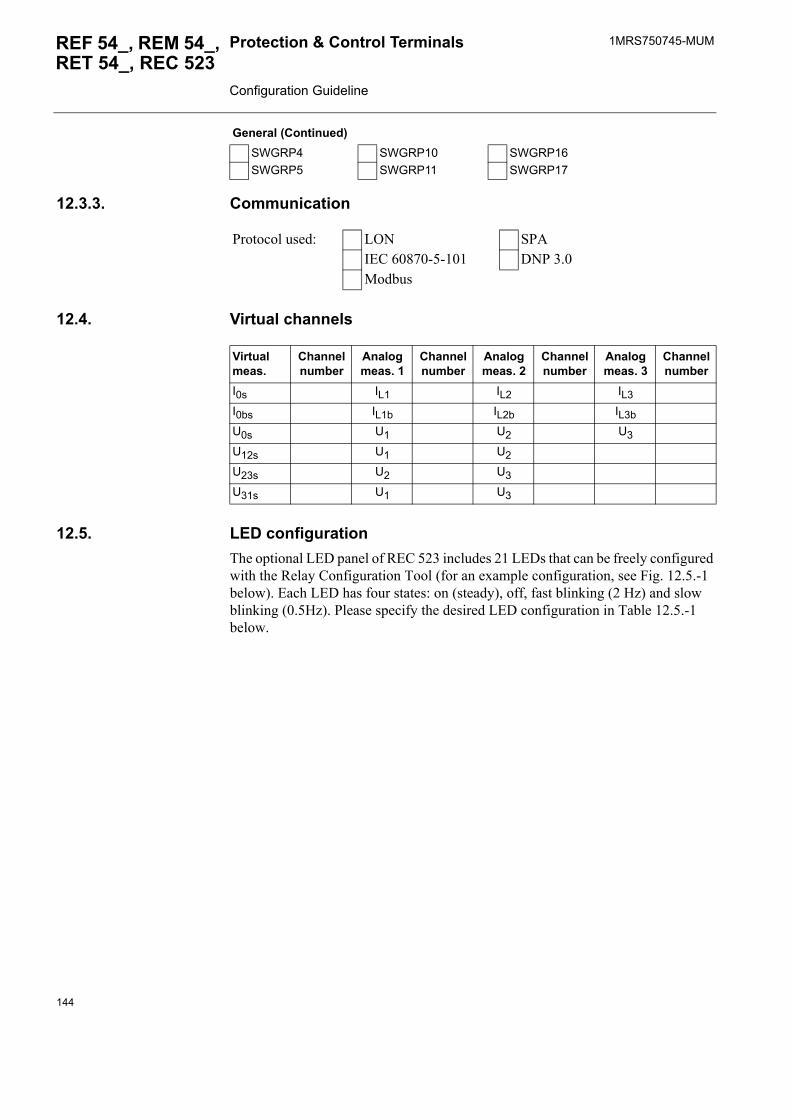
1MRS750745-MUMProtection & Control Terminals Configuration Guideline
REF 54_, REM 54_, RET 54_, REC 523
12.3.3. Communication
12.4. Virtual channels
12.5. LED configurationThe optional LED panel of REC 523 includes 21 LEDs that can be freely configured with the Relay Configuration Tool (for an example configuration, see Fig. 12.5.-1 below). Each LED has four states: on (steady), off, fast blinking (2 Hz) and slow blinking (0.5Hz). Please specify the desired LED configuration in Table 12.5.-1 below.
SWGRP4 SWGRP10 SWGRP16SWGRP5 SWGRP11 SWGRP17
General (Continued)
Protocol used: LON SPAIEC 60870-5-101 DNP 3.0Modbus
Virtual meas.
Channel number
Analog meas. 1
Channel number
Analog meas. 2
Channel number
Analog meas. 3
Channel number
I0s IL1 IL2 IL3I0bs IL1b IL2b IL3bU0s U1 U2 U3U12s U1 U2U23s U2 U3U31s U1 U3
144
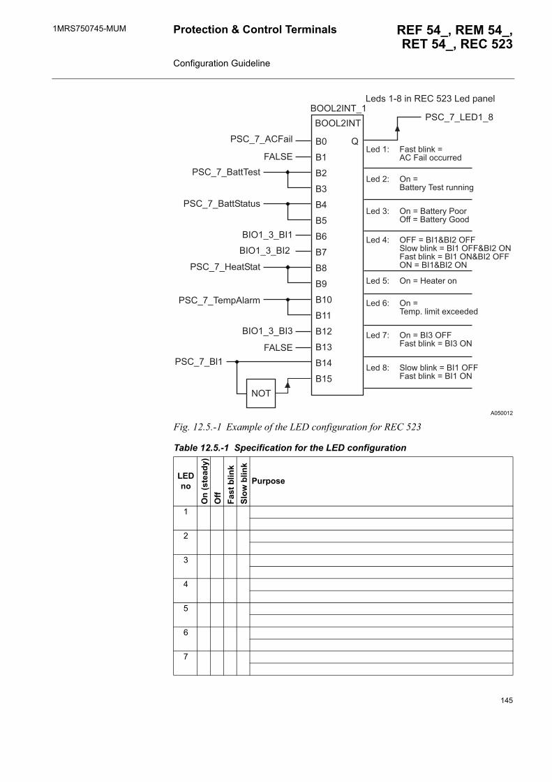
1MRS750745-MUM REF 54_, REM 54_,RET 54_, REC 523
Protection & Control Terminals Configuration Guideline
A050012
Fig. 12.5.-1 Example of the LED configuration for REC 523
Table 12.5.-1 Specification for the LED configuration
LED no
On
(ste
ady)
Off
Fast
blin
kSl
ow b
link
Purpose
1
2
3
4
5
6
7
��
��
��
��
��
��
��
��
���
���
���
��
�
��
���
���
=6�
/'#5�5� �
/'#5�5���*� ���
/'#5�5:��%'%�%
/'#5�5��%%'%�%!.
/'#5�5��%%��.%
/'#5�5�#-��
-�A'2
��6�5 5���
��6�5 5���
-�A'2
��6�5 5��
>
/'#5�5A2,�5�
A��.��7�����12#��� �A���*���
A����+� -�.%�" ��?�B�#�-�� ��$$!����
A����+� 6��B��%%��)���.%��!����(
A��� +� 6��B���%%��)�/���6���B���%%��)�C���
A����+ 6--�B����D����6--' �8�" ��?�B�����6--D����6=-�.%�" ��?�B�����6=D����6--6=�B����D����6=
A����+ 6��B�:��%�����
A����+ 6��B���*� ���%��E$�����
A����+ 6��B��� �6---�.%�" ��?�B��� �6=
A����+ ' �8�" ��?�B�����6---�.%�" ��?�B�����6=
�66A��=�
�66A��=�5�
145
1MRS750745-MUMProtection & Control Terminals Configuration Guideline
REF 54_, REM 54_, RET 54_, REC 523
12.6. Remote monitoring and control unit settingsResponsibility:
8
9
10
11
12
13
14
15
16
17
18
19
20
21
Table 12.5.-1 Specification for the LED configuration
LED no
On
(ste
ady)
Off
Fast
blin
kSl
ow b
link
Purpose
The end user defines the remote monitoring and control unit settingsRemote monitoring and control unit settings according to the turn-key principle
The setting of the parameters is not part of the configuration. The end user will normally be responsible for the setting parameters.
Further information:
146
1MRS750745-MUM REF 54_, REM 54_,RET 54_, REC 523
Protection & Control Terminals Configuration Guideline
13. APPENDIX F: Power quality application guide for harmonics
13.1. Power quality and harmonicsPower quality is a topic that defines the limits for delivered electricity in power network. The key issue is to define acceptable variation limits to ensure that end-customers are able to utilise the delivered power. Power quality is ultimately a customer-driven issue.
Excellent power without interruptions is the ultimate target. Today this target has not been reached. There are many kind of disturbances in the network affecting power quality. Interruptions and other disturbances weaken the utilisation of delivered power in end-customer facilities. If these disturbances have noticeable effects on the utilisation of power, disturbances should be blocked out or the system should be made immune to these disturbances. Before taking action to reduce the effects of disturbances, the reason and source of the disturbance should be found. Only after that can reasonable solutions be weighted against costs and benefits.
Harmonics, that is, distortion in the voltage and current waveforms, are one of the factors affecting power quality. Harmonic distortion is caused by non-linear loads that are, for example, electronic power supplies, converters, arc furnaces and arc welders. Harmonics may cause maloperation of devices, additional heating in devices and telecommunication interference. The importance of harmonics is emphasized by the fact that the amount of equipment generating harmonics constantly increases. Still, it should be noticed that the existence of harmonics is not automatically a problem.
13.2. Background for harmonicsA periodic distorted waveform can be expressed as a sum of sinusoids. The waveform can be represented as a sum of pure sine waves in which the frequency of each sinusoid is an integer multiple of the fundamental frequency. This multiple h is called a harmonic of the fundamental. Harmonics added to the fundamental frequency can be odd harmonics (the integer multiple h is 3,5,7...) or even harmonics (where h is 2,4,6...). In Fig. 13.2.-1 odd harmonics with the amplitude 0.1 p.u. of the fundamental are added to the fundamental frequency.
147
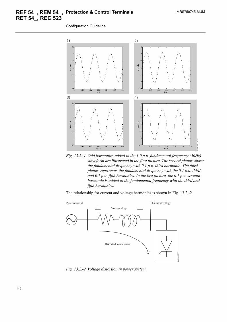
1MRS750745-MUMProtection & Control Terminals Configuration Guideline
REF 54_, REM 54_, RET 54_, REC 523
Fig. 13.2.-1 Odd harmonics added to the 1.0 p.u. fundamental frequency (50Hz) waveform are illustrated in the first picture. The second picture shows the fundamental frequency with 0.1 p.u. third harmonic. The third picture represents the fundamental frequency with the 0.1 p.u. third and 0.1 p.u. fifth harmonics. In the last picture, the 0.1 p.u. seventh harmonic is added to the fundamental frequency with the third and fifth harmonics.
The relationship for current and voltage harmonics is shown in Fig. 13.2.-2.
Fig. 13.2.-2 Voltage distortion in power system
Odd
harm
.CN
V
1) 2)
3) 4)
Voltage drop
Pure Sinusoid Distorted voltage
Distorted load current
Vol
tdis
t.CN
V
148
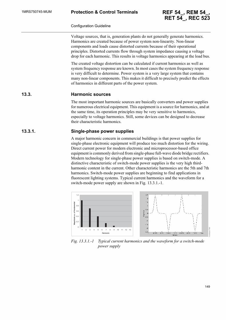
1MRS750745-MUM REF 54_, REM 54_,RET 54_, REC 523
Protection & Control Terminals Configuration Guideline
Voltage sources, that is, generation plants do not generally generate harmonics. Harmonics are created because of power system non-linearity. Non-linear components and loads cause distorted currents because of their operational principles. Distorted currents flow through system impedance causing a voltage drop for each harmonic. This results in voltage harmonics appearing at the load bus.
The created voltage distortion can be calculated if current harmonics as well as system frequency response are known. In most cases the system frequency response is very difficult to determine. Power system is a very large system that contains many non-linear components. This makes it difficult to precisely predict the effects of harmonics in different parts of the power system.
13.3. Harmonic sourcesThe most important harmonic sources are basically converters and power supplies for numerous electrical equipment. This equipment is a source for harmonics, and at the same time, its operation principles may be very sensitive to harmonics, especially to voltage harmonics. Still, some devices can be designed to decrease their characteristic harmonics.
13.3.1. Single-phase power suppliesA major harmonic concern in commercial buildings is that power supplies for single-phase electronic equipment will produce too much distortion for the wiring. Direct current power for modern electronic and microprocessor-based office equipment is commonly derived from single-phase full-wave diode bridge rectifiers. Modern technology for single-phase power supplies is based on switch-mode. A distinctive characteristic of switch-mode power supplies is the very high third-harmonic content in the current. Other characteristic harmonics are the 5th and 7th harmonics. Switch-mode power supplies are beginning to find applications in fluorescent lighting systems. Typical current harmonics and the waveform for a switch-mode power supply are shown in Fig. 13.3.1.-1.
Fig. 13.3.1.-1 Typical current harmonics and the waveform for a switch-mode power supply
0
0.2
0.4
0.6
0.8
1
1.2
1 2 3 4 5 6 7 8 9 10 11 12 13
Harmonic
Mag
nitu
de p
.u. o
f fun
dam
enta
l
Cur
rhar
m.C
NV
149
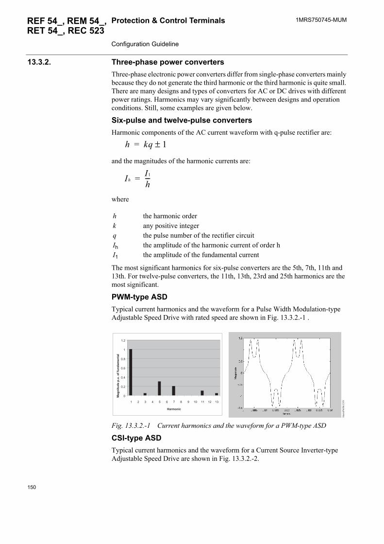
1MRS750745-MUMProtection & Control Terminals Configuration Guideline
REF 54_, REM 54_, RET 54_, REC 523
13.3.2. Three-phase power convertersThree-phase electronic power converters differ from single-phase converters mainly because they do not generate the third harmonic or the third harmonic is quite small. There are many designs and types of converters for AC or DC drives with different power ratings. Harmonics may vary significantly between designs and operation conditions. Still, some examples are given below.
Six-pulse and twelve-pulse convertersHarmonic components of the AC current waveform with q-pulse rectifier are:
and the magnitudes of the harmonic currents are:
where
The most significant harmonics for six-pulse converters are the 5th, 7th, 11th and 13th. For twelve-pulse converters, the 11th, 13th, 23rd and 25th harmonics are the most significant.
PWM-type ASDTypical current harmonics and the waveform for a Pulse Width Modulation-type Adjustable Speed Drive with rated speed are shown in Fig. 13.3.2.-1 .
Fig. 13.3.2.-1 Current harmonics and the waveform for a PWM-type ASD
CSI-type ASDTypical current harmonics and the waveform for a Current Source Inverter-type Adjustable Speed Drive are shown in Fig. 13.3.2.-2.
h the harmonic orderk any positive integerq the pulse number of the rectifier circuitIh the amplitude of the harmonic current of order hI1 the amplitude of the fundamental current
h kq 1±=
IhI1
h---=
0
0.2
0.4
0.6
0.8
1
1.2
1 2 3 4 5 6 7 8 9 10 11 12 13
Harmonic
Mag
nitu
de p
.u. o
f fun
dam
enta
l
Har
mPW
M.C
NV
150
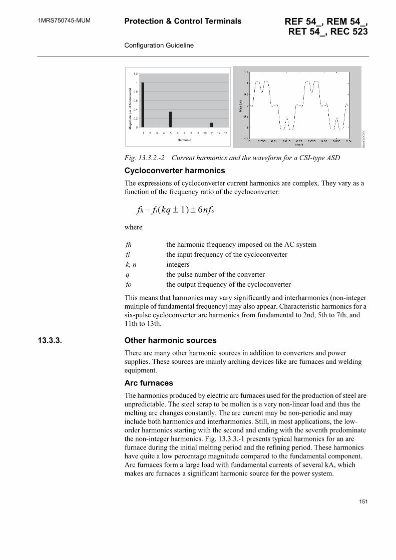
1MRS750745-MUM REF 54_, REM 54_,RET 54_, REC 523
Protection & Control Terminals Configuration Guideline
Fig. 13.3.2.-2 Current harmonics and the waveform for a CSI-type ASD
Cycloconverter harmonicsThe expressions of cycloconverter current harmonics are complex. They vary as a function of the frequency ratio of the cycloconverter:
where
This means that harmonics may vary significantly and interharmonics (non-integer multiple of fundamental frequency) may also appear. Characteristic harmonics for a six-pulse cycloconverter are harmonics from fundamental to 2nd, 5th to 7th, and 11th to 13th.
13.3.3. Other harmonic sourcesThere are many other harmonic sources in addition to converters and power supplies. These sources are mainly arching devices like arc furnaces and welding equipment.
Arc furnacesThe harmonics produced by electric arc furnaces used for the production of steel are unpredictable. The steel scrap to be molten is a very non-linear load and thus the melting arc changes constantly. The arc current may be non-periodic and may include both harmonics and interharmonics. Still, in most applications, the low-order harmonics starting with the second and ending with the seventh predominate the non-integer harmonics. Fig. 13.3.3.-1 presents typical harmonics for an arc furnace during the initial melting period and the refining period. These harmonics have quite a low percentage magnitude compared to the fundamental component. Arc furnaces form a large load with fundamental currents of several kA, which makes arc furnaces a significant harmonic source for the power system.
fh the harmonic frequency imposed on the AC systemfi the input frequency of the cycloconverterk, n integersq the pulse number of the converterfo the output frequency of the cycloconverter
0
0.2
0.4
0.6
0.8
1
1.2
1 2 3 4 5 6 7 8 9 10 11 12 13
Harmonic
Mag
nitu
de p
.u. o
f fun
dam
enta
l
Har
mC
SI.C
NV
fh fi kq 1±( ) 6nfo±=
151
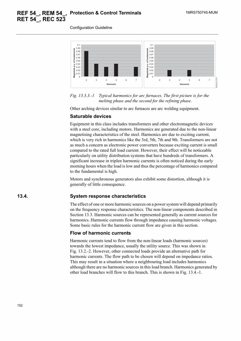
1MRS750745-MUMProtection & Control Terminals Configuration Guideline
REF 54_, REM 54_, RET 54_, REC 523
Fig. 13.3.3.-1 Typical harmonics for arc furnaces. The first picture is for the melting phase and the second for the refining phase.
Other arching devices similar to arc furnaces are arc welding equipment.
Saturable devicesEquipment in this class includes transformers and other electromagnetic devices with a steel core, including motors. Harmonics are generated due to the non-linear magnetising characteristics of the steel. Harmonics are due to exciting current, which is very rich in harmonics like the 3rd, 5th, 7th and 9th. Transformers are not as much a concern as electronic power converters because exciting current is small compared to the rated full load current. However, their effect will be noticeable particularly on utility distribution systems that have hundreds of transformers. A significant increase in triplen harmonic currents is often noticed during the early morning hours when the load is low and thus the percentage of harmonics compared to the fundamental is high.
Motors and synchronous generators also exhibit some distortion, although it is generally of little consequence.
13.4. System response characteristicsThe effect of one or more harmonic sources on a power system will depend primarily on the frequency response characteristics. The non-linear components described in Section 13.3. Harmonic sources can be represented generally as current sources for harmonics. Harmonic currents flow through impedance causing harmonic voltages. Some basic rules for the harmonic current flow are given in this section.
Flow of harmonic currentsHarmonic currents tend to flow from the non-linear loads (harmonic sources) towards the lowest impedance, usually the utility source. This was shown in Fig. 13.2.-2. However, other connected loads provide an alternative path for harmonic currents. The flow path to be chosen will depend on impedance ratios. This may result in a situation where a neighbouring load includes harmonics although there are no harmonic sources in this load branch. Harmonics generated by other load branches will flow to this branch. This is shown in Fig. 13.4.-1.
00.010.020.030.040.050.060.070.080.090.1
2 3 4 5 6 7
Harmonic
Mag
nitu
de p
.u. o
f fun
dam
enta
l0
0.010.020.030.040.050.060.070.080.090.1
2 3 4 5 6 7
Harmonic
Mag
nitu
de p
.u. o
f fun
dam
enta
l
Har
mfu
rn.C
NV
152
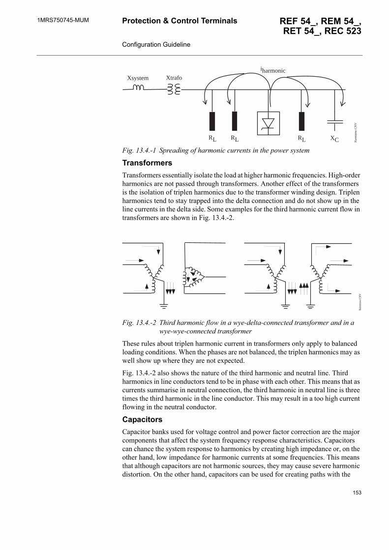
1MRS750745-MUM REF 54_, REM 54_,RET 54_, REC 523
Protection & Control Terminals Configuration Guideline
Fig. 13.4.-1 Spreading of harmonic currents in the power system
TransformersTransformers essentially isolate the load at higher harmonic frequencies. High-order harmonics are not passed through transformers. Another effect of the transformers is the isolation of triplen harmonics due to the transformer winding design. Triplen harmonics tend to stay trapped into the delta connection and do not show up in the line currents in the delta side. Some examples for the third harmonic current flow in transformers are shown in Fig. 13.4.-2.
Fig. 13.4.-2 Third harmonic flow in a wye-delta-connected transformer and in a wye-wye-connected transformer
These rules about triplen harmonic current in transformers only apply to balanced loading conditions. When the phases are not balanced, the triplen harmonics may as well show up where they are not expected.
Fig. 13.4.-2 also shows the nature of the third harmonic and neutral line. Third harmonics in line conductors tend to be in phase with each other. This means that as currents summarise in neutral connection, the third harmonic in neutral line is three times the third harmonic in the line conductor. This may result in a too high current flowing in the neutral conductor.
CapacitorsCapacitor banks used for voltage control and power factor correction are the major components that affect the system frequency response characteristics. Capacitors can chance the system response to harmonics by creating high impedance or, on the other hand, low impedance for harmonic currents at some frequencies. This means that although capacitors are not harmonic sources, they may cause severe harmonic distortion. On the other hand, capacitors can be used for creating paths with the
Xsystem Xtrafo
RL RL RL XC
iharmonic
Har
mpo
w.C
NV
Har
mtr
an.C
NV
153
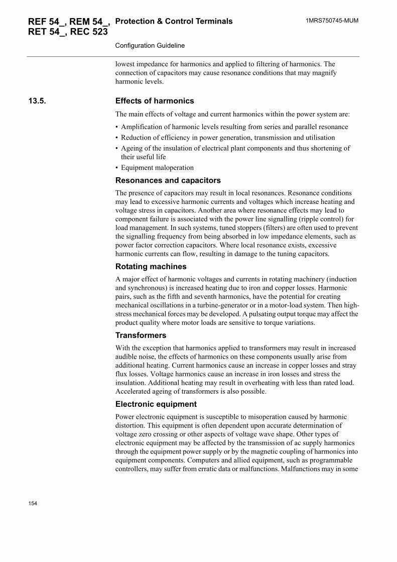
1MRS750745-MUMProtection & Control Terminals Configuration Guideline
REF 54_, REM 54_, RET 54_, REC 523
lowest impedance for harmonics and applied to filtering of harmonics. The connection of capacitors may cause resonance conditions that may magnify harmonic levels.
13.5. Effects of harmonicsThe main effects of voltage and current harmonics within the power system are:
� Amplification of harmonic levels resulting from series and parallel resonance� Reduction of efficiency in power generation, transmission and utilisation� Ageing of the insulation of electrical plant components and thus shortening of
their useful life� Equipment maloperation
Resonances and capacitorsThe presence of capacitors may result in local resonances. Resonance conditions may lead to excessive harmonic currents and voltages which increase heating and voltage stress in capacitors. Another area where resonance effects may lead to component failure is associated with the power line signalling (ripple control) for load management. In such systems, tuned stoppers (filters) are often used to prevent the signalling frequency from being absorbed in low impedance elements, such as power factor correction capacitors. Where local resonance exists, excessive harmonic currents can flow, resulting in damage to the tuning capacitors.
Rotating machinesA major effect of harmonic voltages and currents in rotating machinery (induction and synchronous) is increased heating due to iron and copper losses. Harmonic pairs, such as the fifth and seventh harmonics, have the potential for creating mechanical oscillations in a turbine-generator or in a motor-load system. Then high-stress mechanical forces may be developed. A pulsating output torque may affect the product quality where motor loads are sensitive to torque variations.
TransformersWith the exception that harmonics applied to transformers may result in increased audible noise, the effects of harmonics on these components usually arise from additional heating. Current harmonics cause an increase in copper losses and stray flux losses. Voltage harmonics cause an increase in iron losses and stress the insulation. Additional heating may result in overheating with less than rated load. Accelerated ageing of transformers is also possible.
Electronic equipmentPower electronic equipment is susceptible to misoperation caused by harmonic distortion. This equipment is often dependent upon accurate determination of voltage zero crossing or other aspects of voltage wave shape. Other types of electronic equipment may be affected by the transmission of ac supply harmonics through the equipment power supply or by the magnetic coupling of harmonics into equipment components. Computers and allied equipment, such as programmable controllers, may suffer from erratic data or malfunctions. Malfunctions may in some
154
1MRS750745-MUM REF 54_, REM 54_,RET 54_, REC 523
Protection & Control Terminals Configuration Guideline
cases have serious consequences, for example in medical equipment. Less dramatic interference may occasionally be observed in radio and television equipment, as well as in video recorders and audio reproduction systems.
MeteringMetering instruments initially calibrated on pure sinusoidal alternating current and subsequently used on a distorted electricity supply may be prone to error. Both positive and negative metering errors are possible because error is connected to the direction of the harmonic flow. In general, the distortion must be severe (>20%) before significant errors are detected.
Telephone interferenceThe presence of harmonic currents or voltages in circuitry associated with power conversion apparatus may produce magnetic and electric fields that will impair the satisfactory performance of the communication system that, by virtue of its proximity and susceptibility, may be disturbed.
13.6. Applications for harmonic measurementsHarmonics measurement function blocks can be utilised in applications like monitoring power quality affected by harmonics, monitoring harmonics in selected points of the network and locating sources of harmonics.
13.6.1. Power quality and harmonicsThere are several standards and recommendations for acceptable levels of harmonics in power system. Recommendations for both voltage and current harmonics can be found for distributed electricity. European Standard EN 50160 and IEEE Std 1159-1995 are well known references for power quality.
Harmonic measurements can be utilised in several ways in the network. Here a utility 110/20 kV substation is taken as an example. The substation is shown in Fig. 13.6.1.-1 with measurement points for currents and voltages on 20 kV side. There are three feeders connected to busbar. Feeders have different types of loads connected. Load A is generating harmonic currents and load B is a simple motor or resistive load. In addition, there is a capacitor unit connected to the busbar for reactive power compensation. This unit could also include load.
155
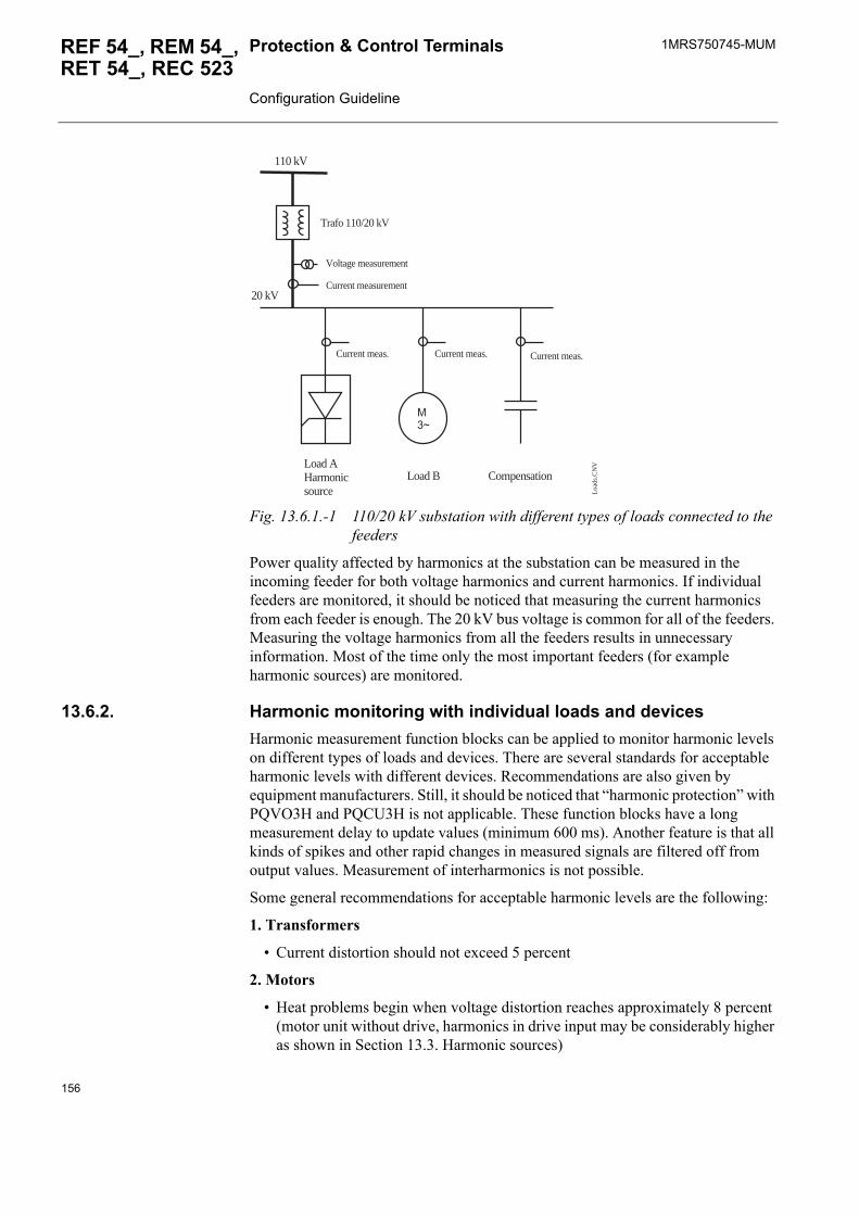
1MRS750745-MUMProtection & Control Terminals Configuration Guideline
REF 54_, REM 54_, RET 54_, REC 523
Fig. 13.6.1.-1 110/20 kV substation with different types of loads connected to the feeders
Power quality affected by harmonics at the substation can be measured in the incoming feeder for both voltage harmonics and current harmonics. If individual feeders are monitored, it should be noticed that measuring the current harmonics from each feeder is enough. The 20 kV bus voltage is common for all of the feeders. Measuring the voltage harmonics from all the feeders results in unnecessary information. Most of the time only the most important feeders (for example harmonic sources) are monitored.
13.6.2. Harmonic monitoring with individual loads and devicesHarmonic measurement function blocks can be applied to monitor harmonic levels on different types of loads and devices. There are several standards for acceptable harmonic levels with different devices. Recommendations are also given by equipment manufacturers. Still, it should be noticed that �harmonic protection� with PQVO3H and PQCU3H is not applicable. These function blocks have a long measurement delay to update values (minimum 600 ms). Another feature is that all kinds of spikes and other rapid changes in measured signals are filtered off from output values. Measurement of interharmonics is not possible.
Some general recommendations for acceptable harmonic levels are the following:
1. Transformers
� Current distortion should not exceed 5 percent
2. Motors
� Heat problems begin when voltage distortion reaches approximately 8 percent (motor unit without drive, harmonics in drive input may be considerably higher as shown in Section 13.3. Harmonic sources)
M3~
Load AHarmonicsource
Load B Compensation
Trafo 110/20 kV
Voltage measurement
Current measurement
110 kV
20 kV
Current meas. Current meas. Current meas.
Loa
ds.C
NV
156
1MRS750745-MUM REF 54_, REM 54_,RET 54_, REC 523
Protection & Control Terminals Configuration Guideline
3. Capacitors
� Voltage limit to 120 percent of peak voltage (with harmonics) -> sum of individual voltage harmonics <20% with rated fundamental
In case of feeders containing many individual loads and devices, it is difficult to recommend levels according to specific devices. In such a case, the recommendations given in standards for power quality can be followed. Then the harmonics are monitored for the feeder itself, not for the load devices.
13.6.3. Locating sources of harmonicsOn radial utility distribution feeders and industrial plant power systems, the main tendency is for harmonic currents to flow from the harmonic producing load (Load A in Fig. 13.6.1.-1) to the power system source (towards 110 kV incoming). The impedance of the power system is normally the lowest impedance seen by the harmonic currents.
There are factors that may alter the path for at least one harmonic. These factors were discussed in Section 13.3. Harmonic sources. Transformers may block some harmonics, power factor correction capacitors may provide paths for higher-order harmonics, and there may be harmonic filters.
To locate the harmonic source (Load A), harmonic currents in all feeders, including the incoming feeder, should be measured. These results should be checked against each other. The harmonic source is the one containing the largest amount of harmonics. It may also be useful to check the harmonic flow while the power factor capasitances are not connected. In this situation, paths for harmonics should be decreased and locating the sources of harmonics should be easier.
13.6.4. Harmonic filter performance monitoringHarmonic filters are designed to catch harmonic currents produced by harmonic sources. There can be filters for a single harmonic component or filter banks for several harmonic components, like the 5th, 7th, 11th and 13th harmonics. The current harmonic measurement function block can be utilised to evaluate how well the harmonic components are caught into the filters. In case of a filter bank designed to catch several harmonic components, the connection of the filter bank to the system may lead to a situation where uncharacteristic (mostly even) harmonic components are created. These uncharacteristic harmonics may have unwanted effects on the system performance and the filter bank. Even though the level of uncharacteristic harmonics is low and negligible after installation, the harmonic levels may be considerably magnified due to the ageing of capacitors in the filter bank.
157

158
1MRS750745-MUM REF 54_, REM 54_,RET 54_, REC 523
Protection & Control Terminals Configuration Guideline
14. Index
AAnalog channels ................................................................................. 28, 39
BBlocking ................................................................................................... 74Bypass mode ............................................................................................. 76
CCode body worksheet ......................................................................... 21, 22Communication ........................................................................................ 71Communication signals ................................................................ 71, 72, 73Compiling the project ............................................................................... 57Condition monitoring ......................................................................... 36, 46Configuration ............................................................ 17, 26, 77, 79, 97, 117Configuration error ............................................................................. 31, 41Configuration specification for REC 523 ............................................... 135Control of switchgears .............................................................................. 75Cyclic communication check ................................................................... 74Cyclic sending generation ........................................................................ 73
DData types ................................................................................................. 19Description worksheet ........................................................................ 21, 22Digital inputs ................................................................................ 34, 45, 63Digital outputs .......................................................................................... 63Downloading the configuration ................................................................ 57
EError outputs ............................................................................................. 66Events ....................................................................................................... 76Execution order ........................................................................................ 67Explicit feedback ...................................................................................... 64
FF-key ......................................................................................................... 68Frequency ................................................................................................. 32
GGlobal variables .................................................................................. 49, 52
HHardware version ................................................................................ 27, 38Harmonic restraint measurement ........................................................ 30, 40Harmonics ............................................................................................... 147HMI .................................................................................................... 66, 74Horizontal communication ....................................................................... 71
159
1MRS750745-MUMProtection & Control Terminals Configuration Guideline
REF 54_, REM 54_, RET 54_, REC 523
LLibraries ................................................................................................... 19Logic ........................................................................................................ 71Logical POUs ..................................................................................... 19, 23
MManuals .................................................................................................... 10Measurement function blocks ...................................................... 30, 40, 76Measurements ......................................................................... 30, 35, 40, 46MIMIC ......................................................... 57, 93, 96, 112, 115, 130, 133
NNeutral current .......................................................................................... 31
PPhysical hardware .............................................................................. 19, 25Polling ...................................................................................................... 71Power quality ......................................................................................... 147Program Organisation Unit (POU) ........................................................... 21Project tree ................................................................................................ 19
RReferences .............................................................................................. 157Relay configuration procedure ................................................................. 77Relay Configuration Tool ........................................................................ 15
SSpecification for REF 54_ Feeder Terminal Configuration ..................... 79Specification for REM 54_ Machine Terminal Configuration ................ 97Specification for RET 54_ Transformer Terminal Configuration ......... 117
TTask interval ............................................................................................. 48Tasks ........................................................................................................ 47Technical data .......................................................................................... 30True RMS measurement ..................................................................... 30, 40
VVariable worksheet ....................................................................... 21, 22, 51Virtual channels .................................................................................. 32, 42
WWarnings .................................................................................................. 67
160


ABB OyDistribution Automation P.O. Box 699FI-65101 VaasaFINLANDTel. +358 10 22 11Fax. +358 10 224 1094www.abb.com/substationautomation
1MR
S75
0745
-MU
M E
N 0
7.20
05