Embed Size (px)
Citation preview
15
20
25
30
35
40
45
2
4
6
8
10
12
14
160.998
1
1.002
1.004
TIME [s]GENERATOR [NUMB]
SP
EE
D [p
u]
Protection Strategies to Mitigate Major Power System Breakdowns
Mattias Jonsson
Department of Electric Power EngineeringCHALMERS UNIVERSITY OF TECHNOLOGYGöteborg, Sweden 2003

THESIS FOR THE DEGREE OF DOCTOR OF PHILOSOPHY
Protection Strategies to Mitigate Major Power
System Breakdowns
by
MATTIAS JONSSON
Department of Electric Power Engineering
Chalmers University of Technology
Göteborg, Sweden 2003
Protection Strategies to Mitigate Major Power System Breakdowns
MATTIAS JONSSON
ISBN 91-7291-293-6
© MATTIAS JONSSON, 2003.
Doktorsavhandlingar vid Chalmers tekniska högskola
Ny serie nr 1975
ISSN 0346-718X
School of Electrical Engineering
Chalmers University of Technology
Technical Report No. 447
ISSN 1651-498X
Department of Electric Power Engineering
Chalmers University of Technology
SE-412 96 Göteborg
Sweden
Telephone: +46 (0)31 - 772 1660
Fax: +46 (0)31 - 772 1633
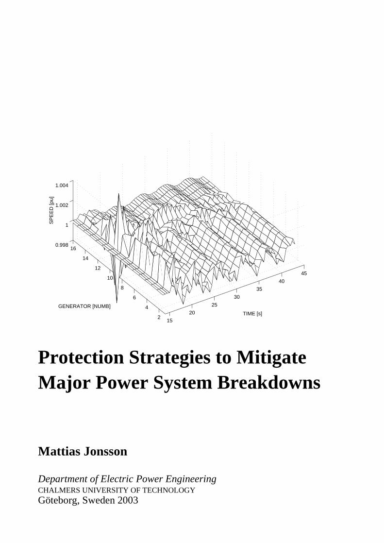
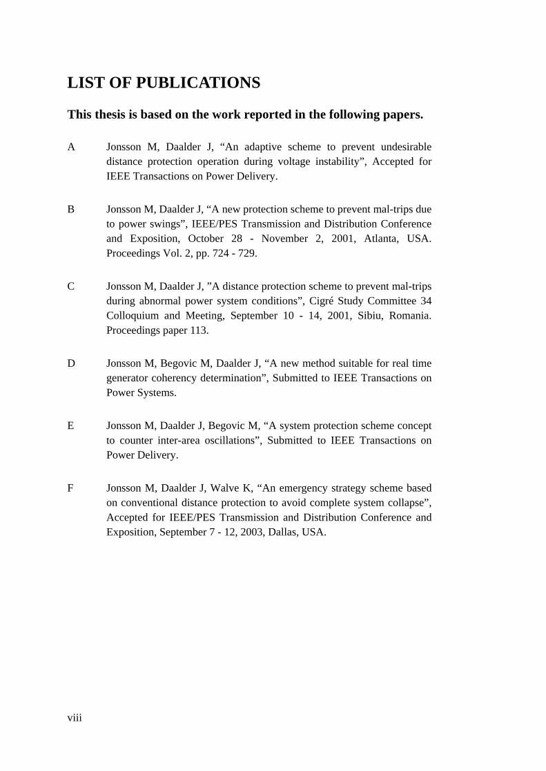
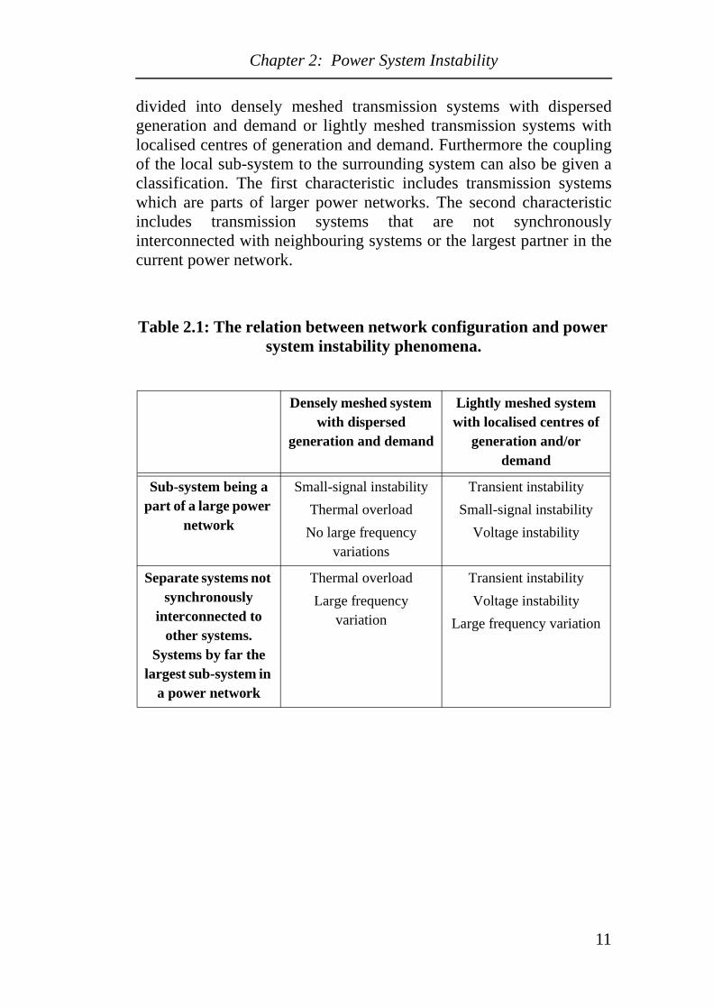
Cover: Inter-area modes in the 68 bus NPCC system.
Chalmers bibliotek, Reproservice
Göteborg, Sweden 2003
iv
Abstract
This thesis deals with new methods to improve the performance ofpower system protection in the case of voltage- and transientinstability. These methods are designed primarily to mitigate powersystem breakdown. Relay algorithms are proposed where conventionaldistance protection is combined with additional relay criteria. In caseof voltage instability the criteria are based on the derivative of thevoltage whereas the rate of change of the phase angle of the current isused for transient instability. For generator coherency determination amethod based on wide area generator speed measurements and Fourieranalysis is proposed. Using this method a concept for a SystemProtection Scheme addressing inter-area events is introduced. Finally,an emergency scheme based on conventional distance relays isproposed to avoid a complete system collapse in the case of severevoltage instability.
The performance of these new methods has been compared withconventional methods based on simulations using different testsystems.
The proposed relay algorithms improve the relay security with respectto voltage instability whereas the reach of the distance protection is notrestricted. Neither the line length, different swing frequencies or faultshaving a slowly decreasing impedance will affect the performance ofthe proposed schemes as may be the case when using conventionalPower Swing Detectors. The fault clearing will also not be blocked aswith conventional PSD applications. The proposed method forestablishing generator coherency leads to almost identical results ifcompared with off-line methods as modal analysis or generator speed.Results obtained from phasor measurements however showeddeviations. This work also demonstrates that, taking initial transientdistortion after a contingency into account, a reliable coherency isfaster obtained by the proposed technique than by methods using purespeed or generator voltage angle measurements. It has beendemonstrated that the proposed emergency scheme can save part of thesystem from a voltage collapse. Black-start can then be avoided andthe restoration time can be reduced.
Keywords: Distance protection, Generator coherency, Out-of-StepProtection, Power Swing Detectors, Voltage instability, SystemProtection Schemes, Transient instability, Wide Area Protection.
v

vi

Acknowledgements
I owe my deepest gratitude to my advisor Professor Jaap Daalder. Firstfor accepting me as a student, then for the support and help he hasgiven me throughout the project. Finally for what I appreciate the most,that he has given me the feeling that his ”door is always open” when Ihad any kind of problem.
Dag Holmberg at Svenska Kraftnät is acknowledged for his efforts inarranging the financial support for this project. The members of mysteering group Magnus Danielsson, Leif Koppari, Lars Wallin andKenneth Walve are acknowledged for their valuable contributions. Allgroup members are with Svenska Kraftnät. Additional staff at SvenskaKraftnät that I would like to thank for their help and support areAnders Edström, Anders Fransson (nowadays with SvenskaEnergihuset), Dag Ingemansson, Bertil Kielén, Allan Lundberg,Thomas Thor and Karl-Olof Jonsson. I also would like to thank themanagement of Svenska Kraftnät for funding the ARISTO computer.
ABB Power Systems are acknowledged for providing SIMPOW freeof charge. Special thanks go to Sune Sarri, Lars Lindkvist and JonasPersson for their valuable help with SIMPOW. In addition I would liketo thank Stefan Arnborg, Svenska Kraftnät for being so generous withhis ”dsl models” when I started to work with SIMPOW.
I am deeply grateful to Magnus Akke, Lars Messing and DanielKarlsson, all with ABB Automation Technology Products AB, for theirunrestrained way of sharing their great expertise in the area.
I would like to sincerely thank Associate Professor Miroslav Begovicat Georgia Institute of Technology, Atlanta, USA for accepting me as avisiting scholar in his research group during the spring and summer,2002.
Annika, Arne, Jan-Olov and Valborg thank you for all help withvarious practical things, I really appreciate it.
Many thanks to all the staff and former colleagues at the Department ofElectric Power Engineering for the pleasant working atmosphere andyour friendship.
Finally, I owe my deepest gratitude to Jenny-Ann and my parents, forunderstanding, encouragement and love throughout this project.
vii
LIST OF PUBLICATIONS
This thesis is based on the work reported in the following papers.
A Jonsson M, Daalder J, “An adaptive scheme to prevent undesirabledistance protection operation during voltage instability”, Accepted forIEEE Transactions on Power Delivery.
B Jonsson M, Daalder J, “A new protection scheme to prevent mal-trips dueto power swings”, IEEE/PES Transmission and Distribution Conferenceand Exposition, October 28 - November 2, 2001, Atlanta, USA.Proceedings Vol. 2, pp. 724 - 729.
C Jonsson M, Daalder J, ”A distance protection scheme to prevent mal-tripsduring abnormal power system conditions”, Cigré Study Committee 34Colloquium and Meeting, September 10 - 14, 2001, Sibiu, Romania.Proceedings paper 113.
D Jonsson M, Begovic M, Daalder J, “A new method suitable for real timegenerator coherency determination”, Submitted to IEEE Transactions onPower Systems.
E Jonsson M, Daalder J, Begovic M, “A system protection scheme conceptto counter inter-area oscillations”, Submitted to IEEE Transactions onPower Delivery.
F Jonsson M, Daalder J, Walve K, “An emergency strategy scheme basedon conventional distance protection to avoid complete system collapse”,Accepted for IEEE/PES Transmission and Distribution Conference andExposition, September 7 - 12, 2003, Dallas, USA.
viii
Contents
Abstract ............................................................................................... vAcknowledgements ...........................................................................viiList of Publications ..........................................................................viiiContents.............................................................................................. ix
Chapter 1 Introduction ................................................................... 11.1 Background and Motivation ...................................................................... 11.2 Outline of the Thesis .................................................................................. 2
Chapter 2 Power System Instability .............................................. 52.1 Angle Instability - Power Oscillations ....................................................... 5
2.1.1 Transient Angle Instability ................................................................ 52.1.2 Small-Signal Angle Instability .......................................................... 6
2.2 Voltage Instability ...................................................................................... 72.3 Frequency Instability ................................................................................. 92.4 The Relation Between Network Configuration and System
Instability Phenomena .............................................................................. 10
Chapter 3 Power System Instability andLocal Area Protection ................................................. 13
3.1 Distance Protection and Voltage Instability ............................................ 133.1.1 Distance Protection may Contribute to Voltage Instability ............ 133.1.2 Worldwide Experience on Voltage Collapse Related to
Distance Protection ......................................................................... 163.2 Distance Protection and Transient Instability .......................................... 18
3.2.1 Distance Protection During Transient Instability ............................ 183.2.2 Power Swing Detectors - Out-of-Step Protection ........................... 223.2.3 Worldwide Experience on Distance Protection and
Transient Instability ......................................................................... 28
Chapter 4 Power System Instability andSystem Protection Schemes ........................................ 31
4.1 System Protection Schemes ..................................................................... 324.1.1 Event- and Response based SPS ..................................................... 344.1.2 Local-, Central-, Remote-, Limited Area and
Wide Area Applications .................................................................. 364.2 Detection and Control Indicators for System Protection Schemes .......... 38
4.2.1 Indicators to Determine Voltage Instability .................................... 384.2.2 Indicators to Determine Transient Angle Instability ....................... 414.2.3 Indicators to Determine Frequency Instability ................................ 43
4.3 Curative Measures for System Protection Schemes ................................ 444.4 System Protection Schemes in the Nordel System .................................. 47
Chapter 5 Summary of Publications ........................................... 535.1 Paper A: An Adaptive Scheme to Prevent Undesirable Distance
Protection Operation During Voltage Instability ..................................... 53
ix
5.2 Paper B: A New Protection Scheme to Prevent Mal-trips due toPower Swings ...........................................................................................53
5.3 Paper C: A Distance Protection Scheme to Prevent Mal-trips DuringAbnormal Power System Conditions .......................................................54
5.4 Paper D: A New Method Suitable for Real Time Generator CoherencyDetermination ...........................................................................................54
5.5 Paper E: A System Protection Scheme Concept to Counter Inter-Area Oscillations ...............................................................................................54
5.6 Paper F: An Emergency Strategy Scheme Based on ConventionalDistance Protection to Avoid Complete System Collapse .......................54
5.7 Other Publications Reported within the Scope of the Project ..................555.7.1 Licentiate thesis - Line Protection and Power System Collapse .....555.7.2 Technical Report - Present Status of System Protection Schemes ..55
Chapter 6 Conclusions and Future Work ................................... 576.1 Conclusions ..............................................................................................576.2 Future Work .............................................................................................59
References ........................................................................................61
Appendix I Summary of Important SPS Features ........................77
x
Chapter 1: Introduction
Chapter 1 Introduction
1.1 Background and Motivation At about 13.00 hrs. on Tuesday December 27, 1983, the Swedishelectrical power system experienced the most severe disturbance of thelast 30 years. The blackout resulted in a number of projects by theutilities and universities where different aspects of the collapse wereinvestigated. Several projects analysed the behaviour of differentpower system elements such as generators, transformers and loadswhile other projects were addressing numerical methods intended toanalyse events similar to the collapse.
These investigations of the 1983 blackout indicated that theperformance of the relay protection system might had been deficient.At the same time developments in computer and communicationtechnologies have significantly enhanced the potential for improvedprotection systems. As a result the project Protection Strategies toMitigate Major Power system Breakdowns was initiated by SvenskaKraftnät1 in co-operation with Chalmers University of Technology.The aim of the project has been to investigate the performance of theexisting relay protection during abnormal operating conditions and toimprove protection methods in order to avoid extensive systembreakdowns.
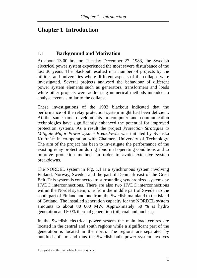
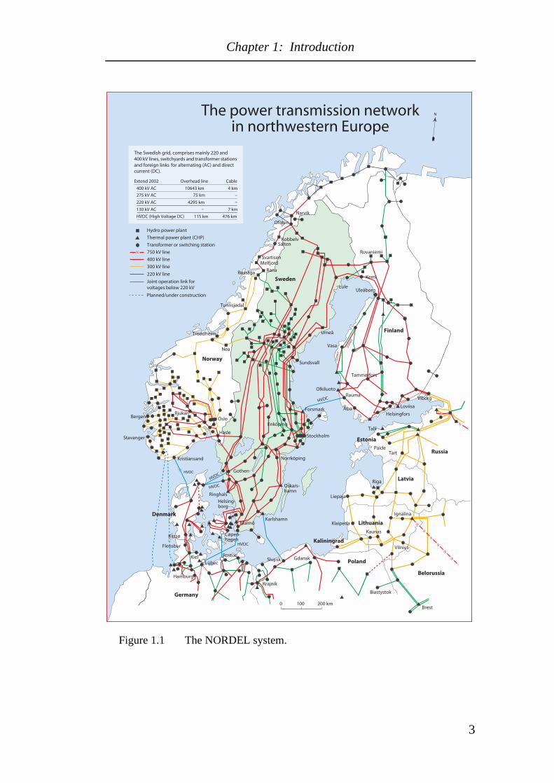
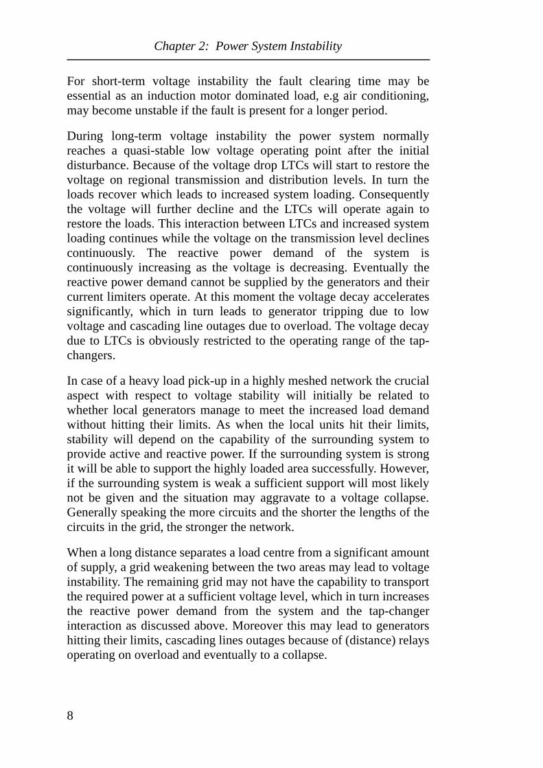
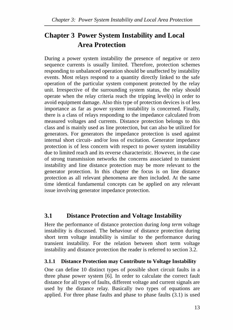
The NORDEL system in Fig. 1.1 is a synchronous system involvingFinland, Norway, Sweden and the part of Denmark east of the GreatBelt. This system is connected to surrounding synchronized systems byHVDC interconnections. There are also two HVDC interconnectionswithin the Nordel system; one from the middle part of Sweden to thesouth part of Finland and one from the Swedish mainland to the islandof Gotland. The installed generation capacity for the NORDEL systemamounts to about 80 000 MW. Approximately 50 % is hydrogeneration and 50 % thermal generation (oil, coal and nuclear).
In the Swedish electrical power system the main load centres arelocated in the central and south regions while a significant part of thegeneration is located in the north. The regions are separated byhundreds of km and thus the Swedish bulk power system involves
1. Regulator of the Swedish bulk power system.
1
Chapter 1: Introduction
large power transfers over long distances. Deregulation resulting in thedecommission of (small) power plants in the south part of Sweden hasfurther enhanced the radial characteristic of the system. Thepossibilities for local generator support in the case of abnormaloperating conditions have obviously been reduced. In addition anincreased variation of power flow directions has been experiencedduring recent years. As a result the main constraints for the NORDELsystem are represented by power system stability issues.
The main ambition in this project has been to improve the protectionperformance during power system instability without jeopardizingfault clearance. During the first part of the project which wasconcluded by the licentiate degree, focus was given to local areaprotection schemes. Furthermore, in the second part concluded by thePh.D degree focus was given to extensive protection systems involvinglarge areas.
1.2 Outline of the ThesisThis dissertation is organized into two parts. The first part gives abackground to the relevant topics while the second part includes sixpapers in which the main technical contributions from this project arepresented.
The background and motivation for the thesis are given in Chapter 1while Chapter 2 summarizes power system instability phenomena.Chapter 3 and Chapter 4 discuss the relevant relations between powersystem instability and power system protection. Chapter 3 treats localarea protection while Chapter 4 discusses System Protection Schemes.Chapter 5 briefly introduces the papers enclosed in the second part ofthis dissertation. Finally, the conclusions and suggestions for futurework are presented in Chapter 6.
At the end of part 1 an appendix and the references of the six firstchapters are included.
2
Chapter 1: Introduction
Figure 1.1 The NORDEL system.
HVDC
HVDC
HVDC
HVDC
(220
kV
)
(220
kV)
N
N
N
N
N
N
N
N
Krajnik
GdanskRostoc
LübecKiel
Hamburg
Flensbur
Ringhals
Helsing-borg
Cøpen-hagen
Gothen-
MalmöKarlshamn
Norrköping
Oskars-hamn
Biastystok
HasleStavanger
BergenRjukan
Oslo
Stockholm
Enköping
Nea
Trondheim
Tunnsjødal
Umeå
Sundsvall
Røssåga Rana
MelfjordSvartisen
Salten
Ofoten
Kobbelv
Narvik
Loviisa
Olkiluoto
Talli
Tart
Riga
Klaipeda
Ignalina
Latvia
Kaunas
Vilnius
Brest
HVDC
Kristiansand
Paide
Rauma
Forsmark
Kassø
0 100 200 km
N
Lule
The power transmission networkin northwestern Europe
Hydro power plant
Thermal power plant (CHP)
Transformer or switching station
750 kV line
400 kV line
300 kV line
N
Joint operation link forvoltages below 220 kV
220 kV line
Extend 2002 CableOverhead line
275 kV AC –75 km
220 kV AC 4295 km
130 kV AC 7 km
The Swedish grid, comprises mainly 220 and400 kV lines, switchyards and transformer stationsand foreign links for alternating (AC) and directcurrent (DC).
400 kV AC 4 km10643 km
Planned/under construction
Sweden
Norway
Finland
Poland
Kaliningrad
Estonia
Lithuania
Russia
Belorussia
Denmark
Germany
Rovaniemi
HelsingforsÅbo
Vasa
Tammerfors
Kemi
Uleåborg
–
HVDC (High Voltage DC) 476 km115 km
–
Liepaja
Viborg
Slupsk
3

Chapter 1: Introduction
4
Chapter 2: Power System Instability
Chapter 2 Power System Instability
In this section a brief summery of power system instability is given.The different types of power system instability are further described byKundur [1] while attention here is given to instability aspects relevantto power system protection. In particular the focus is on the relationbetween grid configuration and system instability due to its importancein the case of protection applications. For simplicity the different typesof power system instability are discussed separately. During a severedisturbance some of these phenomena may occur simultaneouslythough.
2.1 Angle Instability - Power OscillationsThe fundamental phenomena appearing in a power system in case ofangle instability are power oscillations. Depending on their severityand origin they are categorised as transient angle instability or small-signal angle instability.
Generally power oscillations can be divided into three differentcategories; 1) local plant mode oscillations or inter machineoscillations with a frequency range of 0.7 - 2 Hz (6 Hz), 2) inter-areaoscillations, where groups of generators are swinging against eachother in the frequency range of 0.4 - 0.7 Hz and 3) large sub-systemsoscillating against each other where the swinging frequency usually isin the order of 0.1 - 0.3 Hz.
2.1.1 Transient Angle Instability
According to Kundur transient stability is the ability of the powersystem to maintain synchronism when subjected to a severedisturbance such as a fault on transmission facilities, loss ofgeneration, or loss of a large load [1]. Usually this type of disturbancesleads to large excursions of generators angles and significant changesin active and reactive power flows, bus voltages, system frequency andother system variables. Accordingly both the customers and the powersystem are confronted to these features where they have a more or lessdeveloped transient characteristic. In case appropriate counteractionsare not taken transient instability may result in extensive power systemblackouts.
5
Chapter 2: Power System Instability
Loss of synchronism may include one single generating unit, a powerplant represented by multiple generators, a region of the network orseveral interconnected regions. The loss of synchronism may occurduring the first swing after the disturbance or after a number ofdivergent oscillations. In the first case the mismatch between theelectrical and mechanical torque is considered to be the main issuewhile insufficient damping is associated to loss of synchronism after afew swings.
Lightly meshed networks, large power flows and long distance powertransport are features which contribute to transient angle instability.Accordingly tie-lines, bottlenecks and weak interconnections (betweendifferent countries) are typical sources of transient instability. Astransient instability includes large voltage and power variations, fasttripping of power system devices may be initiated due to undesirableprotection operation. This is especially true for some generator and lineprotection [2].
2.1.2 Small-Signal Angle Instability
Small-signal stability is the ability of the power system to maintainsynchronism when subjected to small disturbances. In this context, adisturbance is considered to be small if the equations that describe theresulting response of the system may be linearized for the purpose ofanalysis [1]. Such disturbances happen all the time due to smallvariations in loads and generation. The physical response of the systemmay be a steady increase in rotor angle due to lack of synchronizingtorque or rotor oscillations of increasing amplitude due to lack ofsufficient damping torque. Important to observe is that although theinitial phase can be described by linear behaviour the consequences ofthese oscillations could be non-linear.
Measures to counteract small-signal instability are usually based onclosed-loop controls. These devices provide dynamic control ofelectric quantities of the power system. Typical examples of closed-loop control devices include generator excitation control, powersystem stabilizers (PSS), Static Var Compensators (SVCs) and seriescapacitors with a closed-loop controlled varying capacitance. Closed-loop control devices are not included here as they fall outside the scopeof the project.
Normally, power oscillations associated with small-signal stabilityhave amplitudes which are non-relevant to protection applications.Consequently, in this report we will exclusively discuss the interaction
6
Chapter 2: Power System Instability
between transient instability and protection applications. However, incase small-signal instability results in power oscillations relevant toprotection applications the fundamental principles and relevant issuesapplicable to transient instability are also true for small-signalinstability.
2.2 Voltage InstabilityVoltage stability is concerned with the ability of a power system tomaintain acceptable voltages at all buses in the system under normalconditions and after being subjected to a disturbance. A system enters astate of voltage instability when a disturbance such as an increase inload demand or a change in system conditions causes a progressive anduncontrollable decline in voltage. The main factor causing instability isthe inability of the power system to meet the demand for reactivepower [1]. According to the time duration of load response, voltageinstability can roughly be divided into two different categories; short-term and long-term voltage instability. Induction motors restore theiractive power consumption within one second (short-term) while LoadTap Changers (LTCs) will restore voltage dependent loads within oneto several minutes (long-term). Also thermostatically controlled loadshave a recovery time in the range of minutes. In case of long-termvoltage instability generator current limiters may be activated toprotect the generators from thermal stresses. When current limiters areactivated the operating condition of the power system is often seriouslyaggravated. Particularly armature current limiter activation often leadsto blackouts. In many situations the distinction between voltage andtransient instability is diffuse as aspects of both phenomena may existfor a single disturbance.
Voltage instability may be caused by a variety of single and/or multiplecontingencies. Typical initiating events are heavy load pick-up andgrid weakening. Obviously generator tripping also contributes tovoltage instability; especially tripping of generators located close to theloads supporting the voltage control in that area. Generator trippingcan be the event which initiates voltage instability, but it may also bean accelerating element when it occurs some time into a voltageinstability event.
In case of short-term voltage instability the system may collapse withina few seconds after the disturbance if no curative measures are taken.
7
Chapter 2: Power System Instability
For short-term voltage instability the fault clearing time may beessential as an induction motor dominated load, e.g air conditioning,may become unstable if the fault is present for a longer period.
During long-term voltage instability the power system normallyreaches a quasi-stable low voltage operating point after the initialdisturbance. Because of the voltage drop LTCs will start to restore thevoltage on regional transmission and distribution levels. In turn theloads recover which leads to increased system loading. Consequentlythe voltage will further decline and the LTCs will operate again torestore the loads. This interaction between LTCs and increased systemloading continues while the voltage on the transmission level declinescontinuously. The reactive power demand of the system iscontinuously increasing as the voltage is decreasing. Eventually thereactive power demand cannot be supplied by the generators and theircurrent limiters operate. At this moment the voltage decay acceleratessignificantly, which in turn leads to generator tripping due to lowvoltage and cascading line outages due to overload. The voltage decaydue to LTCs is obviously restricted to the operating range of the tap-changers.
In case of a heavy load pick-up in a highly meshed network the crucialaspect with respect to voltage stability will initially be related towhether local generators manage to meet the increased load demandwithout hitting their limits. As when the local units hit their limits,stability will depend on the capability of the surrounding system toprovide active and reactive power. If the surrounding system is strongit will be able to support the highly loaded area successfully. However,if the surrounding system is weak a sufficient support will most likelynot be given and the situation may aggravate to a voltage collapse.Generally speaking the more circuits and the shorter the lengths of thecircuits in the grid, the stronger the network.
When a long distance separates a load centre from a significant amountof supply, a grid weakening between the two areas may lead to voltageinstability. The remaining grid may not have the capability to transportthe required power at a sufficient voltage level, which in turn increasesthe reactive power demand from the system and the tap-changerinteraction as discussed above. Moreover this may lead to generatorshitting their limits, cascading lines outages because of (distance) relaysoperating on overload and eventually to a collapse.
8
Chapter 2: Power System Instability
The case where generators located close to loads are tripped is similarto the case of a heavy load increase. Also in this case the stability willbe decided by the capability of the surrounding system to provideactive and reactive power to the area lacking generation.
To summarize, voltage instability is especially likely for systemconfigurations where large amounts of power have to be transportedlong distances in a lightly meshed network as in the case for weakinterconnections between remote generation areas and load centres.
In addition to the network configuration also the following aspects areimportant as far as voltage stability is concerned:
•Active and reactive power reserves. For example, generators,synchronous condensers and SVCs. Both the amount of availablereactive power and the location are important.
•Passive reactive power reserves such as capacitors.
•System loading levels. High loading levels are critical.
•Low power factor.
•Load characteristics. Especially the load recovery due to LTCoperation as discussed above (or thermostatic heating).
2.3 Frequency InstabilityFrequency stability describes the ability of a power system to maintainthe system frequency within an acceptable range during normaloperating conditions or after a severe disturbance. Thus frequencyinstability occurs when there is a mismatch between load and supplyand the system cannot compensate for this mismatch before thefrequency reaches an unacceptable value. Typical events which maylead to frequency instability are major outages of generating units andsplitting of the system into isolated areas.
In case normal frequency control measures fail to maintain thefrequency within an acceptable range, it is still important to limitfrequency excursions. Especially generators are sensitive to fairlysmall frequency deviations. Normally generators can operate within aband of ±0.5 Hz related to nominal frequency (50 and 60 Hz systems)without any restrictions. Additionally generators can operate outside
9
Chapter 2: Power System Instability
these values for a limited time period given by manufacturingconstraints.
Publication [3] refers to an example of typical steam turbine limitationsduring abnormal frequency conditions where the worst case limitationshave been specified by five turbine manufactures with respect to 60 Hzoperation [4]. The example indicates that operation between 58.5 and57.9 Hz is permitted for ten minutes during the generator life timebefore turbine blade damage is probable. Note that steam turbines maybe considered to be the weakest link with respect to low frequencyoperation. In Sweden thermal power units are tripped around 47.5 Hzto protect the steam turbines against detrimental vibrations. The hydrounits in operation are more robust and can handle operatingfrequencies down to 45 Hz [5].
Due to its nature protection applications responding to frequencyinstability are normally rather straightforward. For example, unitdevices protecting equipment from damage in the case of frequencyexcursions should respond to a certain frequency deviation present fora specified duration. Accordingly, simple frequency relays withsettings relevant to the current application can be used. Similarly theprocess for System Protection Schemes responding to frequencyinstability is also straightforward, although extensive settingprocedures in order to obtain the optimal curative measures may berequired. Hence, no further attention is explicitly given to frequencyinstability in this dissertation. Still there is a close relationship betweenfrequency- and transient instability and as far as undesirable distanceprotection performance is concerned, the discussion in section 3.2 isalso relevant to events involving frequency instability.
2.4 The Relation Between Network Configuration andSystem Instability Phenomena
As indicated above the network configuration where large amounts ofpower have to be transported long distances over weakinterconnections is vulnerable with respect to power system instability.In Table 2.11 a rough classification has been made with respect to therelation between network configuration and the different power systeminstability phenomena. The different system structures can roughly be
1. The table was originally introduced in [3].
10
Chapter 2: Power System Instability
divided into densely meshed transmission systems with dispersedgeneration and demand or lightly meshed transmission systems withlocalised centres of generation and demand. Furthermore the couplingof the local sub-system to the surrounding system can also be given aclassification. The first characteristic includes transmission systemswhich are parts of larger power networks. The second characteristicincludes transmission systems that are not synchronouslyinterconnected with neighbouring systems or the largest partner in thecurrent power network.
Table 2.1: The relation between network configuration and power system instability phenomena.
Densely meshed system with dispersed
generation and demand
Lightly meshed system with localised centres of
generation and/or demand
Sub-system being a part of a large power
network
Small-signal instability
Thermal overload
No large frequency variations
Transient instability
Small-signal instability
Voltage instability
Separate systems not synchronously
interconnected to other systems.
Systems by far the largest sub-system in
a power network
Thermal overload
Large frequency variation
Transient instability
Voltage instability
Large frequency variation
11

Chapter 2: Power System Instability
12
Chapter 3: Power System Instability and Local Area Protection
Chapter 3 Power System Instability and Local Area Protection
During a power system instability the presence of negative or zerosequence currents is usually limited. Therefore, protection schemesresponding to unbalanced operation should be unaffected by instabilityevents. Most relays respond to a quantity directly linked to the safeoperation of the particular system component protected by the relayunit. Irrespective of the surrounding system status, the relay shouldoperate when the relay criteria reach the tripping level(s) in order toavoid equipment damage. Also this type of protection devices is of lessimportance as far as power system instability is concerned. Finally,there is a class of relays responding to the impedance calculated frommeasured voltages and currents. Distance protection belongs to thisclass and is mainly used as line protection, but can also be utilized forgenerators. For generators the impedance protection is used againstinternal short circuit- and/or loss of excitation. Generator impedanceprotection is of less concern with respect to power system instabilitydue to limited reach and its reverse characteristic. However, in the caseof strong transmission networks the concerns associated to transientinstability and line distance protection may be more relevant to thegenerator protection. In this chapter the focus is on line distanceprotection as all relevant phenomena are then included. At the sametime identical fundamental concepts can be applied on any relevantissue involving generator impedance protection.
3.1 Distance Protection and Voltage InstabilityHere the performance of distance protection during long term voltageinstability is discussed. The behaviour of distance protection duringshort term voltage instability is similar to the performance duringtransient instability. For the relation between short term voltageinstability and distance protection the reader is referred to section 3.2.
3.1.1 Distance Protection may Contribute to Voltage Instability
One can define 10 distinct types of possible short circuit faults in athree phase power system [6]. In order to calculate the correct faultdistance for all types of faults, different voltage and current signals areused by the distance relay. Basically two types of equations areapplied. For three phase faults and phase to phase faults (3.1) is used
13
Chapter 3: Power System Instability and Local Area Protection
where L1 and L2 are the faulted phases. Equation (3.2) is valid forphase to ground fault involving phase L1.
(3.1)
(3.2)
UL1, UL2: Phase voltages at the relay location.
IL1, IL2: Phase currents at the relay location.
I0: Residual (zero sequence-) current at the relay location.
Z1: Positive sequence impedance for the primary protected circuit.
Z0: Zero sequence impedance for the primary protected circuit.
Zr: the apparent impedance as seen by the distance relay.
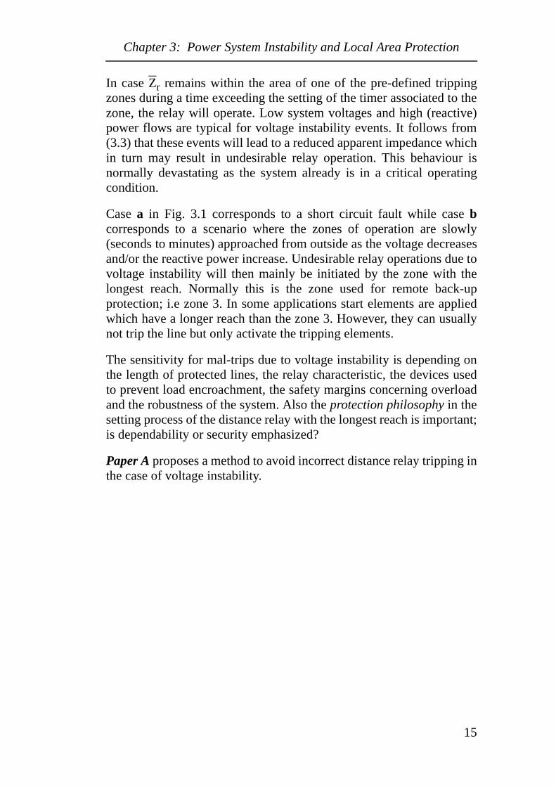
Voltage instability is a phase symmetrical phenomenon. Hence no zerosequence component is present and the phase voltages and currents aresymmetrical. Thus the apparent impedance Zr as seen by a distancerelay during voltage instability is given in (3.3). Here U is the line toline voltage and P and Q are the injected active and reactive power atthe location of the relay.
(3.3)
ZrUL1 UL2–
IL1 IL2–--------------------------=
ZrUL1
IL1Z0 Z1–
Z1
------------------ I0⋅+
------------------------------------------=
ZrUL1
IL1
----------U
2P jQ+( )⋅
P2
Q2
+-----------------------------------= =
14
Chapter 3: Power System Instability and Local Area Protection
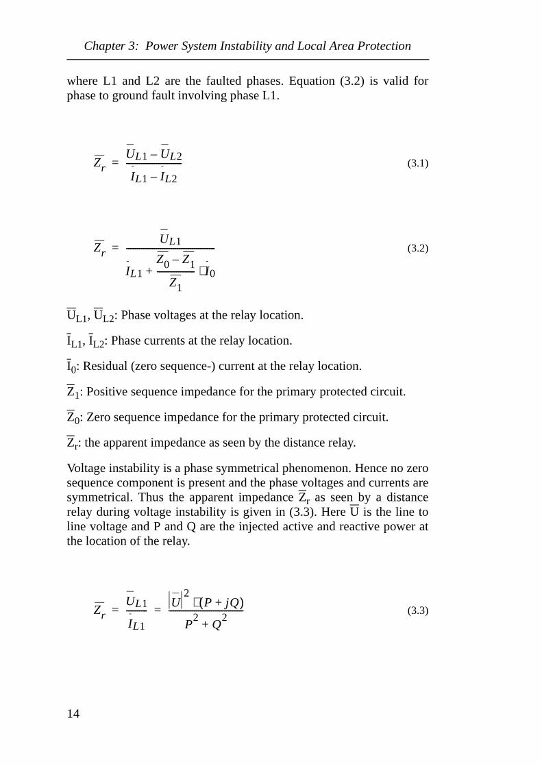
In case Zr remains within the area of one of the pre-defined trippingzones during a time exceeding the setting of the timer associated to thezone, the relay will operate. Low system voltages and high (reactive)power flows are typical for voltage instability events. It follows from(3.3) that these events will lead to a reduced apparent impedance whichin turn may result in undesirable relay operation. This behaviour isnormally devastating as the system already is in a critical operatingcondition.
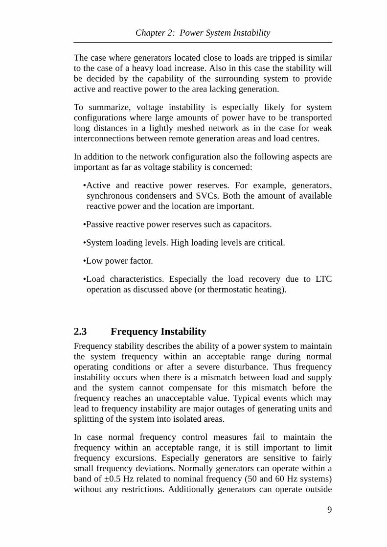
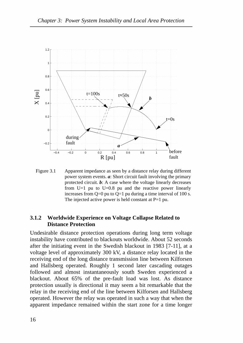
Case a in Fig. 3.1 corresponds to a short circuit fault while case bcorresponds to a scenario where the zones of operation are slowly(seconds to minutes) approached from outside as the voltage decreasesand/or the reactive power increase. Undesirable relay operations due tovoltage instability will then mainly be initiated by the zone with thelongest reach. Normally this is the zone used for remote back-upprotection; i.e zone 3. In some applications start elements are appliedwhich have a longer reach than the zone 3. However, they can usuallynot trip the line but only activate the tripping elements.
The sensitivity for mal-trips due to voltage instability is depending onthe length of protected lines, the relay characteristic, the devices usedto prevent load encroachment, the safety margins concerning overloadand the robustness of the system. Also the protection philosophy in thesetting process of the distance relay with the longest reach is important;is dependability or security emphasized?
Paper A proposes a method to avoid incorrect distance relay tripping inthe case of voltage instability.
15
Chapter 3: Power System Instability and Local Area Protection
Figure 3.1 Apparent impedance as seen by a distance relay during differentpower system events. a: Short circuit fault involving the primaryprotected circuit. b: A case where the voltage linearly decreasesfrom U=1 pu to U=0.8 pu and the reactive power linearlyincreases from Q=0 pu to Q=1 pu during a time interval of 100 s.The injected active power is held constant at P=1 pu.
3.1.2 Worldwide Experience on Voltage Collapse Related to Distance Protection
Undesirable distance protection operations during long term voltageinstability have contributed to blackouts worldwide. About 52 secondsafter the initiating event in the Swedish blackout in 1983 [7-11], at avoltage level of approximately 300 kV, a distance relay located in thereceiving end of the long distance transmission line between Kilforsenand Hallsberg operated. Roughly 1 second later cascading outagesfollowed and almost instantaneously south Sweden experienced ablackout. About 65% of the pre-fault load was lost. As distanceprotection usually is directional it may seem a bit remarkable that therelay in the receiving end of the line between Kilforsen and Hallsbergoperated. However the relay was operated in such a way that when theapparent impedance remained within the start zone for a time longer
−0.4 −0.2 0 0.2 0.4 0.6 0.8 1 1.2
−0.2
0
0.2
0.4
0.6
0.8
1
1.2
R [pu]
X [
pu]
abefore fault
during fault
b
t=0s
t≈50st=100s
16
Chapter 3: Power System Instability and Local Area Protection
than 3.2 seconds without relay operation, the start element aloneinitiated tripping. In such a case the relay behaved as a non-directionalunit with a long reach having a circular impedance characteristic,where operation due to load encroachment was not obstructed.
On July 2, 1996 the WSCC system was operated within its transferlimits and only a few facilities were out of service [12-14]. Due to asingle phase to ground fault resulting in remedial actions, and incorrectrelay operation as a result of mechanical failure the system wassignificantly weakened. About 24 seconds after the initial fault animportant 230 kV line tripped through its zone 3 relay due to moderateoverload and moderate voltage depression. Cascading outages resultedand approximately 10 seconds later the system had separated into fiveelectrical islands. About 2 million customers were affected by thedisturbance. Furthermore, a zone 3 distance relay operated incorrectlyduring the restorative process due to load encroachment and delayedthe restoration of the system.
On March 11, 1999, Brazil [15] faced the most severe powerinterruption in its history. About 72 % of the pre-disturbance loadamounting to 34 200 MW was affected. The initiating event of theblackout was a phase to ground fault in a substation which led to theloss of five incoming 440 kV lines. The system survived thiscontingency and recovered to a quasi stable operating point. About 12seconds after the phase to ground fault another line tripped. Cascadingoutages followed and approximately 18 seconds later the entirenetwork collapsed. The tripping of the line after 12 seconds wasinitiated by the start unit of the distance protection. The start unit hadthe longest reach of all zones of operation to provide remote back-upfor all adjacent lines which are much longer than the given line. Thestart unit had been given a setting corresponding to a very long reachwith an associated time delay of 1.5 seconds. Hence, when the lineloading increased after the initial fault and likely in combination withan increasing reactive power demand throughout the entire system, theapparent impedance entered the start zone and the relay operated.
Further examples where undesirable (zone 3) distance protectionoperations have contributed to blackouts include the ¨November 9,1965 Northeastern U.S/Canada disturbance and the August 22, 1987Western Tennessee U.S blackouts [16].
17
Chapter 3: Power System Instability and Local Area Protection
3.2 Distance Protection and Transient InstabilityPower oscillations are inherent to power systems. They may resultfrom any power system event such as line switching, short circuitfaults, generator tripping or load shedding. During normal operationthe magnitude of the oscillations are usually small and quicklyattenuated. However, during abnormal operation the oscillations can besevere and are in some cases of an increasing nature. In this section therelation between power oscillations and distance protection isexamined.
3.2.1 Distance Protection During Transient Instability
Referring to the frequency range of power oscillations given in 2.1power oscillations may be the source of incorrect relay behaviour asthe cycle times of the oscillations are in the same time range as thetimer settings of the protection devices.
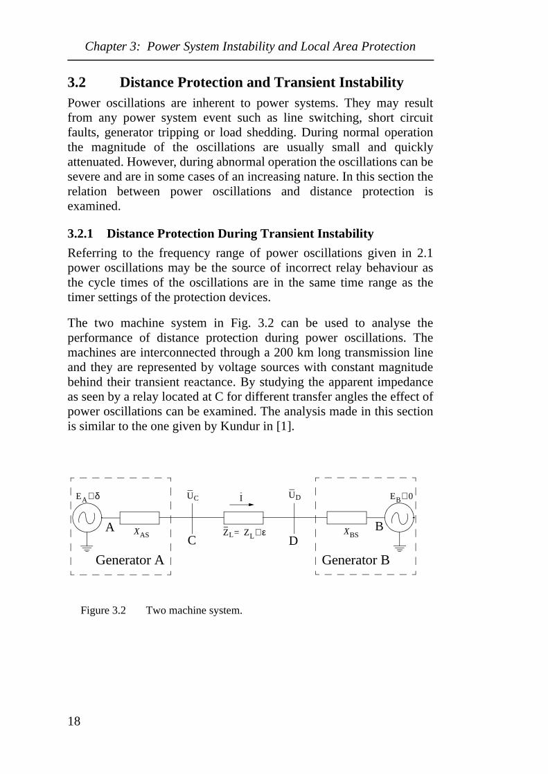
The two machine system in Fig. 3.2 can be used to analyse theperformance of distance protection during power oscillations. Themachines are interconnected through a 200 km long transmission lineand they are represented by voltage sources with constant magnitudebehind their transient reactance. By studying the apparent impedanceas seen by a relay located at C for different transfer angles the effect ofpower oscillations can be examined. The analysis made in this sectionis similar to the one given by Kundur in [1].
Figure 3.2 Two machine system.
XAS
I
Generator A
EA δ∠
ZL ZL ε∠=
Generator B
XBS
EB 0∠UC UD
AC D
B
18
Chapter 3: Power System Instability and Local Area Protection
In Fig. 3.2, EA and EB are the internal voltages of the machines andXAS and XBS are the transient reactances. EB is assumed to be thereference phasor and δ represents the angle by which EA leads EB.Hence the current I is given in (3.4) and the voltage UC in (3.5).
(3.4)
(3.5)
The apparent impedance as seen by the relay at C during phasesymmetrical operation can be determined when (3.4) and (3.5) areinserted into (3.6).
(3.6)
(3.7)
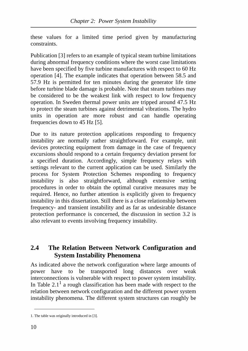
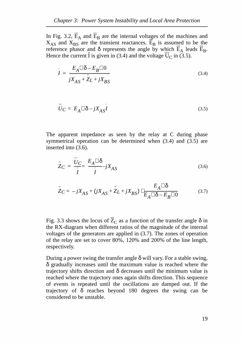
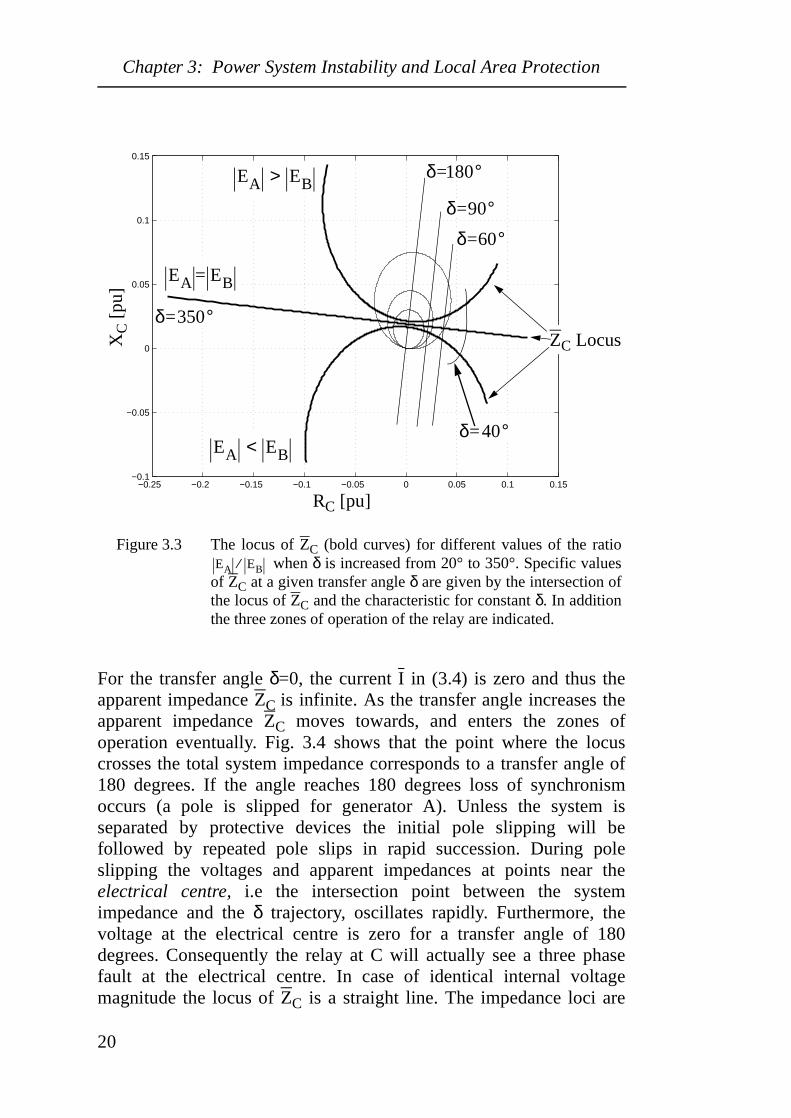
Fig. 3.3 shows the locus of ZC as a function of the transfer angle δ inthe RX-diagram when different ratios of the magnitude of the internalvoltages of the generators are applied in (3.7). The zones of operationof the relay are set to cover 80%, 120% and 200% of the line length,respectively.
During a power swing the transfer angle δ will vary. For a stable swing,δ gradually increases until the maximum value is reached where thetrajectory shifts direction and δ decreases until the minimum value isreached where the trajectory ones again shifts direction. This sequenceof events is repeated until the oscillations are damped out. If thetrajectory of δ reaches beyond 180 degrees the swing can beconsidered to be unstable.
IEA δ∠ EB 0∠–
jXAS ZL jXBS+ +-------------------------------------------=
UC EA δ∠= jXASI–
ZCUC
I-------
EA δ∠
I-------------- jXAS–==
ZC jXAS– jXAS ZL jXBS+ +( )EA δ∠
EA δ∠ EB 0∠–-----------------------------------⋅+=
19
Chapter 3: Power System Instability and Local Area Protection
Figure 3.3 The locus of ZC (bold curves) for different values of the ratio when δ is increased from 20° to 350°. Specific values
of ZC at a given transfer angle δ are given by the intersection ofthe locus of ZC and the characteristic for constant δ. In additionthe three zones of operation of the relay are indicated.
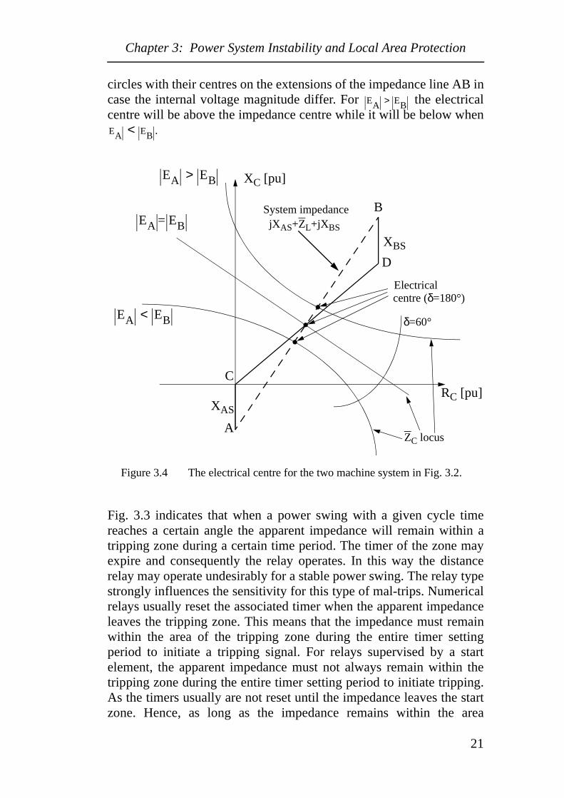
For the transfer angle δ=0, the current I in (3.4) is zero and thus theapparent impedance ZC is infinite. As the transfer angle increases theapparent impedance ZC moves towards, and enters the zones ofoperation eventually. Fig. 3.4 shows that the point where the locuscrosses the total system impedance corresponds to a transfer angle of180 degrees. If the angle reaches 180 degrees loss of synchronismoccurs (a pole is slipped for generator A). Unless the system isseparated by protective devices the initial pole slipping will befollowed by repeated pole slips in rapid succession. During poleslipping the voltages and apparent impedances at points near theelectrical centre, i.e the intersection point between the systemimpedance and the δ trajectory, oscillates rapidly. Furthermore, thevoltage at the electrical centre is zero for a transfer angle of 180degrees. Consequently the relay at C will actually see a three phasefault at the electrical centre. In case of identical internal voltagemagnitude the locus of ZC is a straight line. The impedance loci are
−0.25 −0.2 −0.15 −0.1 −0.05 0 0.05 0.1 0.15−0.1
−0.05
0
0.05
0.1
0.15
RC [pu]
XC
[pu
]
δ 40°=
δ 350°=
δ 60°=
δ 90°=
δ 180°=
ZC Locus
EA EB=
EA EB<
EA EB>
EA EB⁄
20
Chapter 3: Power System Instability and Local Area Protection
circles with their centres on the extensions of the impedance line AB incase the internal voltage magnitude differ. For the electricalcentre will be above the impedance centre while it will be below when
.
Figure 3.4 The electrical centre for the two machine system in Fig. 3.2.
Fig. 3.3 indicates that when a power swing with a given cycle timereaches a certain angle the apparent impedance will remain within atripping zone during a certain time period. The timer of the zone mayexpire and consequently the relay operates. In this way the distancerelay may operate undesirably for a stable power swing. The relay typestrongly influences the sensitivity for this type of mal-trips. Numericalrelays usually reset the associated timer when the apparent impedanceleaves the tripping zone. This means that the impedance must remainwithin the area of the tripping zone during the entire timer settingperiod to initiate a tripping signal. For relays supervised by a startelement, the apparent impedance must not always remain within thetripping zone during the entire timer setting period to initiate tripping.As the timers usually are not reset until the impedance leaves the startzone. Hence, as long as the impedance remains within the area
EA EB>
EA EB<
RC [pu]
XC [pu]
EA EB<
EA EB=
EA EB>
XAS
XBS
C
D
A
B
Electrical centre (δ=180°)
System impedancejXAS+ZL+jXBS
δ=60°
ZC locus
21
Chapter 3: Power System Instability and Local Area Protection
associated to the start element the impedance can enter, leave and re-enter the zones of operation unlimited times and the timer will in anycase continue to count. This means that a tripping signal is generatedimmediately when the zone of operation is entered after the timer hasexpired. If the start element has a shape which surrounds all thetripping zones the area which decides the likelihood for mal-trips dueto power swings has increased. Therefore it is very important to takethis effect into account when power oscillations are considered withrespect to undesirable distance protection operations.
Fig. 3.3 and Fig. 3.4 illustrate the impedance trajectories for a relaylocated in the sending end of a line. The trajectories for the receivingend are identical but reversed.
Observe that the assumption made above where the internal machinereactance and voltages are given fixed values is a rough reflection ofthe system behaviour suitable for illustration. In real operation theelectrical centres are non-fixed points as the internal machineimpedances and voltages will vary during dynamic conditions.
Distance protection should not operate for stable swings. However, inthe case of unstable power swings the protection system should operateto divide the system into stable sub-systems or to separate the ”sick”part of the system from the ”healthy” parts. The issue is furtherdiscussed in the next section.
3.2.2 Power Swing Detectors - Out-of-Step Protection
Different approaches for Power Swing Detectors and Out-of-StepProtection have been suggested throughout the years. In [17] a methodto avoid mal-trips due to high frequency (above 6 Hz) power swings isproposed based on the phase angle of the voltages at the line terminalsand at the fault location. The method is restricted to avoid zone 1 mal-operations due to power swings. Another indicator is proposed in [18-20] where tripping is prevented if the rate of change of an electricquantity exceeds a threshold value. In [21] decision trees are used toclassify a transient swing on the basis of real-time phasormeasurement. Furthermore, neural networks are used in [22] to detectpower swings. An adaptive out-of-step relay is proposed in [23,24]which uses the equal area criterion and GPS technology. Also thealgorithm introduced in [25] applies the equal area criterion to assessthe stability of the generators and determine when pole-slipping willoccur. In [26] circle fitting and parameter estimation are applied todiscriminate power swings from faults. However, the most common
22
Chapter 3: Power System Instability and Local Area Protection
method used for Power Swing Detectors and Out-of-Step Protection isbased on the transition time through a blocking impedance area in theRX-diagram.
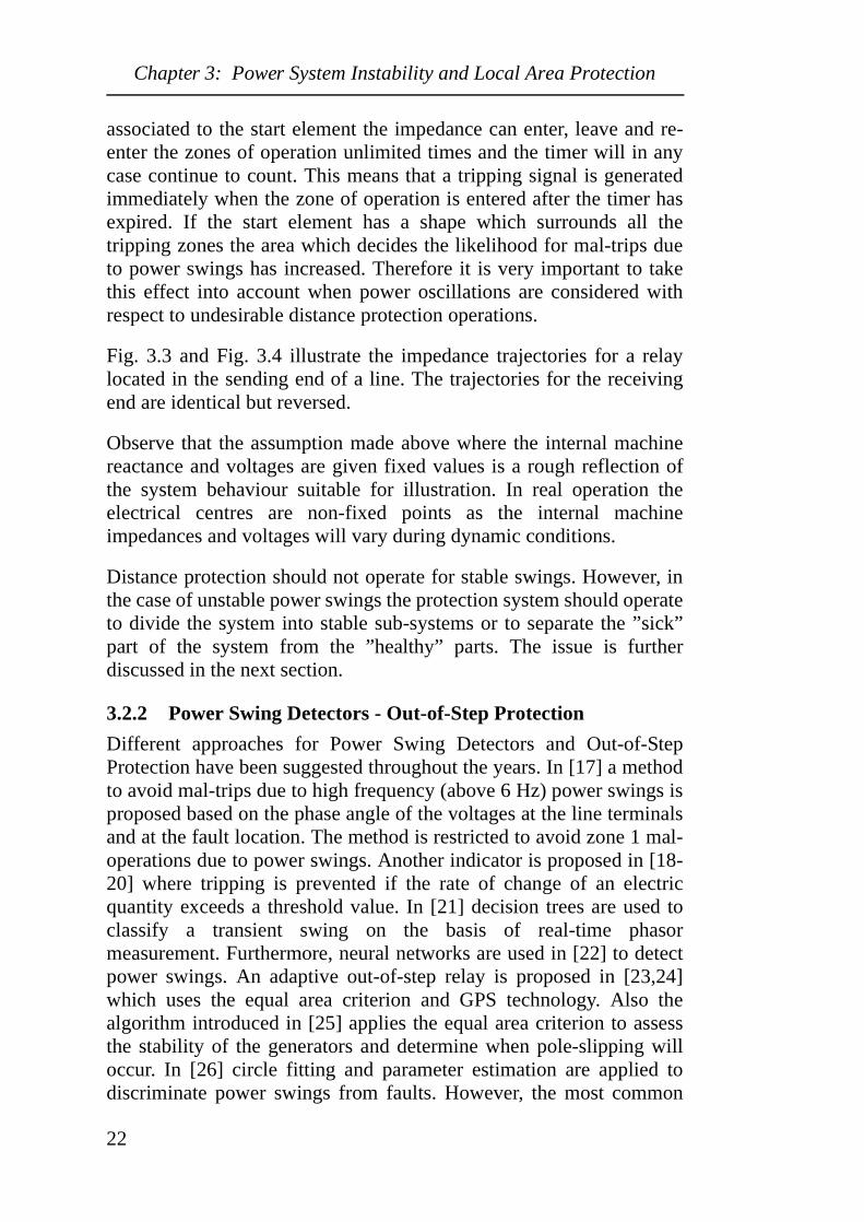
Figure 3.5 Vertical and circular characteristics for Power Swing Detectorschemes. The dashed lines indicate trajectories for the apparentimpedance during a power swing. The left scheme is operated atthe sending end of a line and the right scheme is located at thereceiving end of a line.
Basically the method uses the feature that the movement of theapparent impedance during power swings is slow as compared to itsmovement for short circuit faults. Fig. 3.5 shows two differentcharacteristics of Power Swing Detector (PSD) schemes. When theapparent impedance penetrates the outer circle or line of the PSDschemes a timer is started. If the impedance crosses the grey area veryrapidly the PSD determines a short circuit fault and tripping ispermitted. If the transition time for the apparent impedance through thegrey area exceeds the pre-set timer value, the tripping function isblocked during a certain time. Usually the pre-set value for the timeramounts to about 80 ms and tripping is blocked during a couple ofseconds.
R [Ω]
X [Ω] X [Ω]
R [Ω]
Pre-disturbance
Post-disturbance
Power Swing Detectors (PSD)
23
Chapter 3: Power System Instability and Local Area Protection
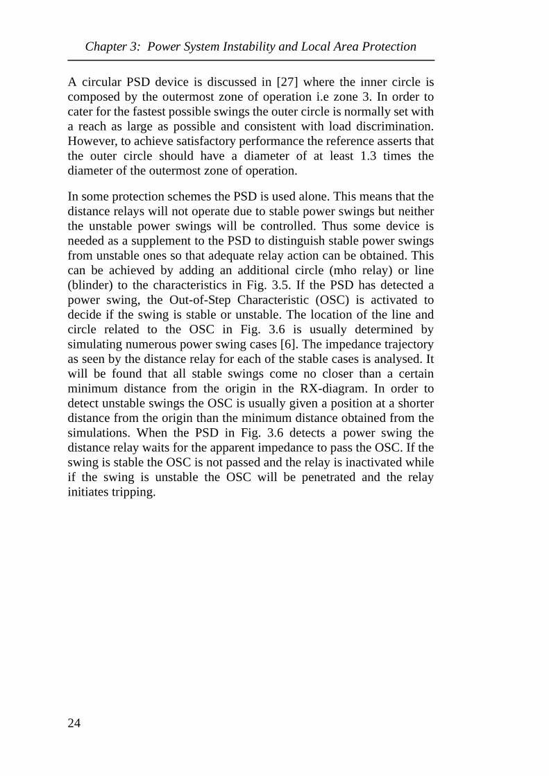
A circular PSD device is discussed in [27] where the inner circle iscomposed by the outermost zone of operation i.e zone 3. In order tocater for the fastest possible swings the outer circle is normally set witha reach as large as possible and consistent with load discrimination.However, to achieve satisfactory performance the reference asserts thatthe outer circle should have a diameter of at least 1.3 times thediameter of the outermost zone of operation.
In some protection schemes the PSD is used alone. This means that thedistance relays will not operate due to stable power swings but neitherthe unstable power swings will be controlled. Thus some device isneeded as a supplement to the PSD to distinguish stable power swingsfrom unstable ones so that adequate relay action can be obtained. Thiscan be achieved by adding an additional circle (mho relay) or line(blinder) to the characteristics in Fig. 3.5. If the PSD has detected apower swing, the Out-of-Step Characteristic (OSC) is activated todecide if the swing is stable or unstable. The location of the line andcircle related to the OSC in Fig. 3.6 is usually determined bysimulating numerous power swing cases [6]. The impedance trajectoryas seen by the distance relay for each of the stable cases is analysed. Itwill be found that all stable swings come no closer than a certainminimum distance from the origin in the RX-diagram. In order todetect unstable swings the OSC is usually given a position at a shorterdistance from the origin than the minimum distance obtained from thesimulations. When the PSD in Fig. 3.6 detects a power swing thedistance relay waits for the apparent impedance to pass the OSC. If theswing is stable the OSC is not passed and the relay is inactivated whileif the swing is unstable the OSC will be penetrated and the relayinitiates tripping.
24
Chapter 3: Power System Instability and Local Area Protection
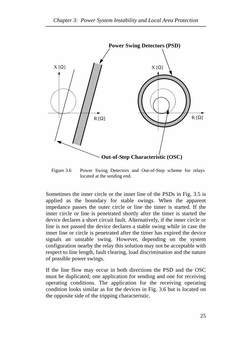
Figure 3.6 Power Swing Detectors and Out-of-Step scheme for relayslocated at the sending end.
Sometimes the inner circle or the inner line of the PSDs in Fig. 3.5 isapplied as the boundary for stable swings. When the apparentimpedance passes the outer circle or line the timer is started. If theinner circle or line is penetrated shortly after the timer is started thedevice declares a short circuit fault. Alternatively, if the inner circle orline is not passed the device declares a stable swing while in case theinner line or circle is penetrated after the timer has expired the devicesignals an unstable swing. However, depending on the systemconfiguration nearby the relay this solution may not be acceptable withrespect to line length, fault clearing, load discrimination and the natureof possible power swings.
If the line flow may occur in both directions the PSD and the OSCmust be duplicated; one application for sending and one for receivingoperating conditions. The application for the receiving operatingcondition looks similar as for the devices in Fig. 3.6 but is located onthe opposite side of the tripping characteristic.
R [Ω]
X [Ω] X [Ω]
R [Ω]
Power Swing Detectors (PSD)
Out-of-Step Characteristic (OSC)
25
Chapter 3: Power System Instability and Local Area Protection
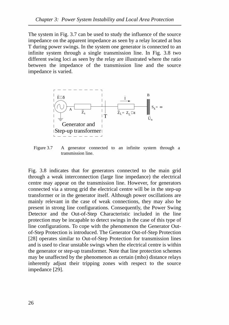
The system in Fig. 3.7 can be used to study the influence of the sourceimpedance on the apparent impedance as seen by a relay located at busT during power swings. In the system one generator is connected to aninfinite system through a single transmission line. In Fig. 3.8 twodifferent swing loci as seen by the relay are illustrated where the ratiobetween the impedance of the transmission line and the sourceimpedance is varied.
Figure 3.7 A generator connected to an infinite system through atransmission line.
Fig. 3.8 indicates that for generators connected to the main gridthrough a weak interconnection (large line impedance) the electricalcentre may appear on the transmission line. However, for generatorsconnected via a strong grid the electrical centre will be in the step-uptransformer or in the generator itself. Although power oscillations aremainly relevant in the case of weak connections, they may also bepresent in strong line configurations. Consequently, the Power SwingDetector and the Out-of-Step Characteristic included in the lineprotection may be incapable to detect swings in the case of this type ofline configurations. To cope with the phenomenon the Generator Out-of-Step Protection is introduced. The Generator Out-of-Step Protection[28] operates similar to Out-of-Step Protection for transmission linesand is used to clear unstable swings when the electrical centre is withinthe generator or step-up transformer. Note that line protection schemesmay be unaffected by the phenomenon as certain (mho) distance relaysinherently adjust their tripping zones with respect to the sourceimpedance [29].
A
B
Zs
I
Generator and
E δ∠
ZL ZL ε∠=
Un
Sk ∞=
T
Step-up transformer
26
Chapter 3: Power System Instability and Local Area Protection
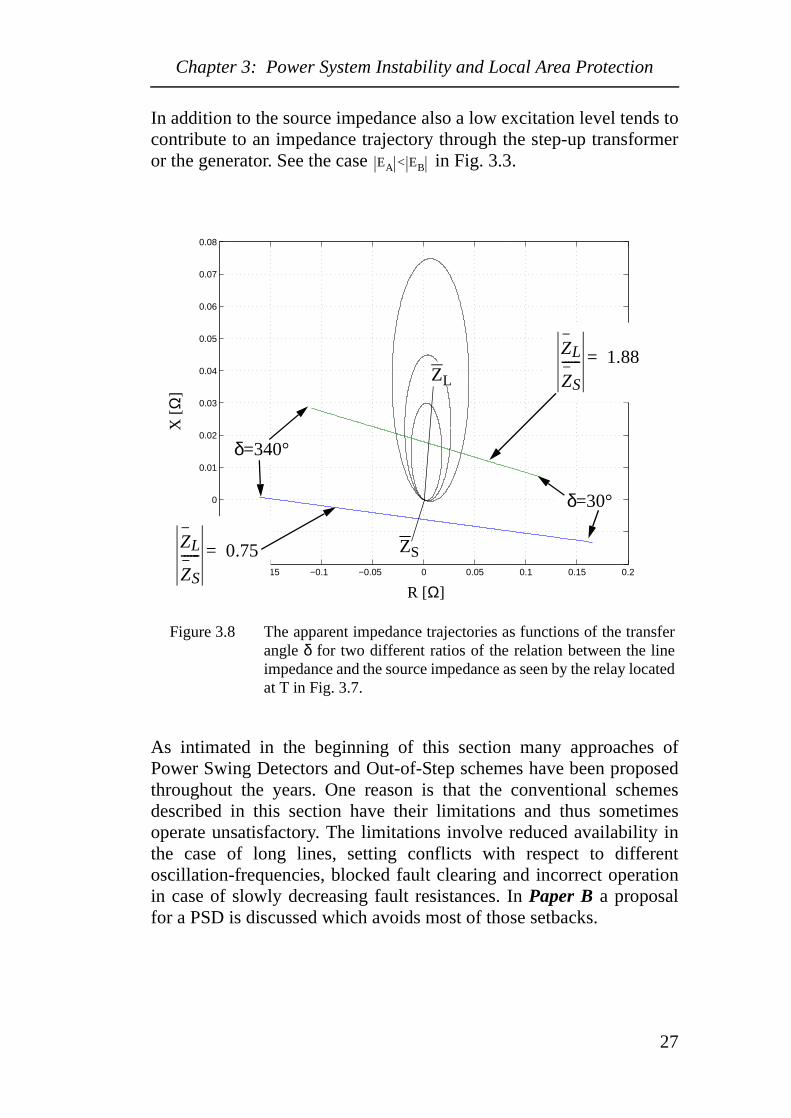
In addition to the source impedance also a low excitation level tends tocontribute to an impedance trajectory through the step-up transformeror the generator. See the case in Fig. 3.3.
Figure 3.8 The apparent impedance trajectories as functions of the transferangle δ for two different ratios of the relation between the lineimpedance and the source impedance as seen by the relay locatedat T in Fig. 3.7.
As intimated in the beginning of this section many approaches ofPower Swing Detectors and Out-of-Step schemes have been proposedthroughout the years. One reason is that the conventional schemesdescribed in this section have their limitations and thus sometimesoperate unsatisfactory. The limitations involve reduced availability inthe case of long lines, setting conflicts with respect to differentoscillation-frequencies, blocked fault clearing and incorrect operationin case of slowly decreasing fault resistances. In Paper B a proposalfor a PSD is discussed which avoids most of those setbacks.
EA < EB
−0.2 −0.15 −0.1 −0.05 0 0.05 0.1 0.15 0.2−0.02
−0.01
0
0.01
0.02
0.03
0.04
0.05
0.06
0.07
0.08
R [Ω]
X [
Ω]
δ=30°
δ=340°
ZL
ZS
------ 1.88=
ZL
ZS
------ 0.75= ZS
ZL
27
Chapter 3: Power System Instability and Local Area Protection
3.2.3 Worldwide Experience on Distance Protection and Transient Instability
In this paragraph a few relevant events are briefly discussed. The datapresented were obtained from a survey carried out by CIGRÉ WG34.09. On July 27, 1989 in Portugal a Power Swing Detector failed tooperate and on August 24, 1993, in Spain three distance relaysoperated due to power swings as the swings had a higher frequencythan the effective range of the blocking unit. Furthermore, on July 18,1995 the WSCC system was subjected to incorrect out-of-stepblocking during non-three phase faults. The location of the out-of-stepprotection was the main reason for inadequate performance during adisturbance in South Africa on June 7, 1996.
In Florida [30] and in South Africa [31] incorrect relay behaviourduring power swings has been (and still is) a major concern.
An unwarranted distance relay operation due to a power swing was theimmediate reason for the system breakdown in the south-western partof Sweden and Denmark in 1956 [32]. As a result power oscillationsand associated protection measures were given significant attention.However, apart from a limited number serving interconnectionsbetween Sweden and the other Nordic countries, all Power SwingDetectors were taken out of service in the middle of the seventies. Tothe author’s knowledge no formal investigation was carried out and thedecision was most likely based on the following arguments. As thetransmission system recently had been reinforced power oscillationswere not expected to cause any trouble and PSDs were thereforeconsidered unnecessary. In addition some doubts were addressedtowards their operational reliability. The general opinion is that poweroscillations were rare in the Swedish transmission system during thisperiod and the removal of the PSDs was never questioned. However, inthe late evening of the New Years day, 1997, the Nordic power systemwas subjected to serious inter-area oscillations. The oscillationsresulted from a busbar fault coincident with large power flows in anunusual direction. A few generator units and lines were lost but no loadwas affected. However, a couple of distance relays were very close totrip due to the impedance swings. In case these relays had orderedtripping a disturbance similar to the 1983 [11] had most likelyoccurred. In case PSDs had been in service, the risk of incorrect relayoperation due to the swings had been eliminated. The number ofrecorded oscillation events has increased significantly during recentyears in the Swedish power system. In 1996 the annual number of
28
Chapter 3: Power System Instability and Local Area Protection
recorded inter-area oscillation events amounted to about 15 while inthe year 2000 this number had increased to more than 300 [33]! In fact,in a few cases, operating conditions have occurred where the systemwas close to its limits and on the brink of a severe disturbance. Notethat about 30 % of the events recorded in 2000 were related to onespecific maintenance job lasting a period of three weeks.
29
Chapter 3: Power System Instability and Local Area Protection
30
Chapter 4: Power System Instability and System Protection Schemes
Chapter 4 Power System Instability and System Protection Schemes
The protection schemes discussed here are intended to counter extremecontingencies and normally involve dispersed system devices fordetection, data acquisition and curative measures. These schemes arereferred to by different names e.g ”System Protection Scheme”, ”WideArea Protection Scheme”, ”Special Protection Scheme”, ”ContingencyArming Scheme”, ”Discrete Supplementary Controls” and ”RemedialAction Scheme”. Normally the expression ”Wide Area ProtectionScheme” is exclusively used for schemes introduced to countercomplex and large phenomena which may jeopardise the integrity ofthe whole system. Other expressions may range from very localschemes to extensive wide area schemes. In a recent report [3]published by CIGRÉ, TF 38.02.19 the term ”System ProtectionScheme” has been selected and will also be used throughout this thesis.
System Protection Schemes are an attractive alternative for increasingthe utilisation of electrical power systems. First of all the economicalaspects are in favour of System Protection Schemes as control andprotection equipment are less expensive than EHV hardwareequipment. Furthermore, System Protection Schemes can mitigatewide area disturbances effectively. Finally, the environmental aspectsof System Protection Schemes are appealing as no new line corridorsare required. The fast progress during recent years within the area ofnumerical and communication technologies has increased the potentialof technically complex and cost-effective System Protection Schemes.The ability to acquire and process wide area data has also improvedsignificantly. The Phasor Measurement Unit [34-36] and inexpensivefibre optics are two attributes which have simplified the realization ofthese features. Particularly the reliability can be improved if comparedto older solutions. Moreover there is a trend today that protection andcontrol functions are merged together in sophisticated substation andcontrol units. This process also facilitates System Protection Schemes.
Extensive surveys over System Protection Schemes have been made byboth Cigré and IEEE [3,37-39]. In addition a number of detailedpublications over specific System Protection Schemes [40-44] andrelated subjects [45-56] have been published. The material in thischapter is to a large extent based on these publications. Appendix 1gives a general overview with respect to the relations between differentpower system events, type of system, network configurations, curative
31
Chapter 4: Power System Instability and System Protection Schemes
measures and the indicators to be used to detect abnormal operatingconditions and initiate the curative measures. The appendix can beconsidered as a summary of the material published in this chapter.
4.1 System Protection SchemesConventional power system protection is mainly used to protect powersystem equipment from damage while the fundamental aim of SystemProtection Schemes is to protect the power system against partial ortotal breakdown. To obtain this objective protective measures are takenwhen abnormal operating conditions are identified. For these occasionsno ”traditional fault situation” is present but the system itself may be intransition to a dangerous situation such as a wide area disturbance or acomplete system blackout. Accordingly the protective measures areused to counteract this transition and bring the system back to a safeoperating condition.
In [3] the following definition is given, ”A System Protection Scheme isdesigned to detect abnormal system conditions and takepredetermined, corrective action (other than the isolation of faultedelements) to preserve system integrity and provide acceptable systemperformance” and in [37] ”A System Protection Scheme is a protectionscheme that is designed to detect a particular system condition that isknown to cause unusual stress to the power system, and to take sometype of predetermined action to counteract the observed condition in acontrolled manner”. Note that in [37] System Protection Schemes arereferred to as Special Protection Schemes.
32
Chapter 4: Power System Instability and System Protection Schemes
System Protection Schemes (SPS) are used for different purposes.Below their main objectives are listed:
1. Operate power systems closer to their limits.Due to deregulation and environmental constraints the operatingmargins have been reduced in many power systems worldwide. SPSare used to operate power systems closer to their limits withoutreducing the operating security of the system or impairing overalleconomic objectives. A typical application may be the reduction ofcongestion limitations between supply and load areas. Similarly, inthe case of limited financial resources SPS may be used to avoid orpostpone reinforcements of the transmission system withoutreducing its operating security.
2. Increase power system security (particularly for extremecontingencies leading to system collapse).By including SPS and maintaining the original operating limits thepower system security can be increased. This type of SPS are oftendesigned to counteract serious disturbances.
3. Improve power system operation.SPS may be designed to cope with operational difficulties imposedby certain power system characteristics. Examples are operatingconditions characterised by a higher rate of exposure to multiplefaults than tolerated by the design criteria or large frequency andvoltage variations in adjacent sub-systems. Actions are typicallytaken when a certain ”key element” is lost or a particular operatingcondition is present.
4. Compensate for delays in a construction program.SPS may be used as a temporary solution such as before and duringthe time a new transmission line is constructed.
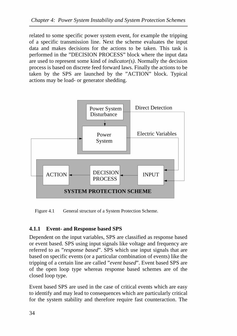
Normally, SPS are dormant integrated protection systems whichoperate infrequently. The control actions taken by SPS are usually pre-determined and the SPS can be armed or disarmed depending on thepower system conditions. Fig. 4.11 shows the general structure of SPS.Generally all SPS include three main functions. First the schemecollects input data from the power system. These input data may bequantities like voltage or frequency. Alternatively, the input data are
1. Originally published in [3].
33
Chapter 4: Power System Instability and System Protection Schemes
related to some specific power system event, for example the trippingof a specific transmission line. Next the scheme evaluates the inputdata and makes decisions for the actions to be taken. This task isperformed in the ”DECISION PROCESS” block where the input dataare used to represent some kind of indicator(s). Normally the decisionprocess is based on discrete feed forward laws. Finally the actions to betaken by the SPS are launched by the ”ACTION” block. Typicalactions may be load- or generator shedding.
Figure 4.1 General structure of a System Protection Scheme.
4.1.1 Event- and Response based SPS
Dependent on the input variables, SPS are classified as response basedor event based. SPS using input signals like voltage and frequency arereferred to as ”response based”. SPS which use input signals that arebased on specific events (or a particular combination of events) like thetripping of a certain line are called ”event based”. Event based SPS areof the open loop type whereas response based schemes are of theclosed loop type.
Event based SPS are used in the case of critical events which are easyto identify and may lead to consequences which are particularly criticalfor the system stability and therefore require fast counteraction. The
Disturbance
PowerSystem
ACTION DECISION INPUTPROCESS
Electric Variables
Direct Detection
SYSTEM PROTECTION SCHEME
Power System
34
Chapter 4: Power System Instability and System Protection Schemes
main benefit of event based SPS are their fast response. Thefundamental idea of event based schemes is to initiate curative actionsquickly and before overall system behaviour becomes degraded. Thistype of schemes may be very effective as rapid control actions to limitelectromechanical dynamics before system stability is threatened.Event based schemes are based on rules obtained from off-linesimulations. Typical examples of applications are generation rejectionor remote load shedding initiated by the tripping of a specifictransmission line. The major drawback of event based SPS is theirreliability, as the performance of the schemes normally relies on alimited number of critical variables.
Response based SPS are inherently slower than event based SPS asthey must wait for the system response; e.g the frequency or voltage todrop below a certain threshold. On the other hand response based SPSare more general than event based SPS as they react with respect tocritical system quantities whatever the cause of the disturbance. Eventbased SPS will only take action in the case of specific events.Accordingly, response based SPS are also efficient for events that arenot explicitly identified or foreseen. Response based SPS are usuallysimple and secure schemes and their reliability depend mainly on thevariables chosen and their behaviour. Moreover, these schemes areusually insensitive to the failure of a single component as they areoften decentralised. Two common examples of response based SPS areunderfrequency- and undervoltage load shedding.
35
Chapter 4: Power System Instability and System Protection Schemes
4.1.2 Local-, Central-, Remote-, Limited Area and Wide Area Applications
System Protection Schemes can be based on local, central-, remote-,limited area or wide area arrangements.
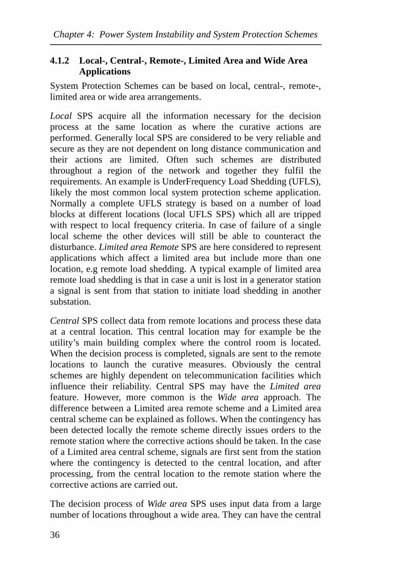
Local SPS acquire all the information necessary for the decisionprocess at the same location as where the curative actions areperformed. Generally local SPS are considered to be very reliable andsecure as they are not dependent on long distance communication andtheir actions are limited. Often such schemes are distributedthroughout a region of the network and together they fulfil therequirements. An example is UnderFrequency Load Shedding (UFLS),likely the most common local system protection scheme application.Normally a complete UFLS strategy is based on a number of loadblocks at different locations (local UFLS SPS) which all are trippedwith respect to local frequency criteria. In case of failure of a singlelocal scheme the other devices will still be able to counteract thedisturbance. Limited area Remote SPS are here considered to representapplications which affect a limited area but include more than onelocation, e.g remote load shedding. A typical example of limited arearemote load shedding is that in case a unit is lost in a generator stationa signal is sent from that station to initiate load shedding in anothersubstation.
Central SPS collect data from remote locations and process these dataat a central location. This central location may for example be theutility’s main building complex where the control room is located.When the decision process is completed, signals are sent to the remotelocations to launch the curative measures. Obviously the centralschemes are highly dependent on telecommunication facilities whichinfluence their reliability. Central SPS may have the Limited areafeature. However, more common is the Wide area approach. Thedifference between a Limited area remote scheme and a Limited areacentral scheme can be explained as follows. When the contingency hasbeen detected locally the remote scheme directly issues orders to theremote station where the corrective actions should be taken. In the caseof a Limited area central scheme, signals are first sent from the stationwhere the contingency is detected to the central location, and afterprocessing, from the central location to the remote station where thecorrective actions are carried out.
The decision process of Wide area SPS uses input data from a largenumber of locations throughout a wide area. They can have the central
36
Chapter 4: Power System Instability and System Protection Schemes
approach but can also be represented by a number of remote stationsinteracting with each other. SPS based on a network of remote stationstogether with central schemes are obviously more complex than localSPS and are strongly dependent on communication tools. For theseschemes the security is the main concern as in case of undesirableoperation (during normal operation) the consequences will besignificant. The different types of SPS arrangements are illustrated inFig. 4.2.
Figure 4.2 Illustration of Limited-/Wide area Central and Remoteapplications.
Wide Area RemoteLimited Area Remote
Wide Area CentralLimited Area Central
CENTRAL
REMOTESUBSTAION
REMOTESUBSTAION
REMOTESUBSTAION
REMOTESUBSTAION
CENTRAL
REMOTESUBSTAION
REMOTESUBSTAION
REMOTESUBSTAION
CENTRAL
REMOTESUBSTAION
REMOTESUBSTAION
REMOTESUBSTAION
CENTRAL
REMOTESUBSTAION
REMOTESUBSTAION
REMOTESUBSTAION
REMOTESUBSTAION
37
Chapter 4: Power System Instability and System Protection Schemes
4.2 Detection and Control Indicators for SystemProtection Schemes
In order to obtain appropriate SPS operation, detection and controlindicators are required. A large number of indicators based onsophisticated mathematical methods have been proposed for off-linestudies applicable during the planning phase. However, real-timeapplications require indicators which are obtained very fast and thusthere are few indicators, apart from measured electrical quantities anddirect events, which are applicable. Dimension-less indices are alsosometimes useful, for example in case of long term voltage stabilityevents. However, they are more applicable as guidance for operators.Often the main concerns in case of SPS design may not only be thechoice of indicators but the way of obtaining appropriate setting valuesfor the indicators. The next sections briefly describe indicatorsapplicable for the determination of power system instability.
4.2.1 Indicators to Determine Voltage Instability
Indicators for voltage instability are often related to the maximumloadability of the system. For event based SPS loss of generation,reactive resources and transmission facilities are typically used asindicators as they represent phenomena which may contribute tovoltage instability. In the case of response based SPS the followingindicators based on direct measurement represent the most commoninputs:
•Bus voltage magnitude. In many systems the bus voltage magnitudeis the main indicator available to detect voltage instability.However depending on the location in the system its reliability asan indicator varies significantly. For example, close to generatorsand at buses with a high level of shunt capacitor compensation thevoltage may indicate a too positive system status. For buses locatedaway from generation and with no shunt capacitor compensationthe voltage may well be a valuable indicator.
•Reactive and active power output from generators.
•Reactive power reserves within regions.
•Active and reactive power flows on lines (tie-lines).
•Generator (field/armature) current limiter status.
•Active and reactive load demand.
38
Chapter 4: Power System Instability and System Protection Schemes
Additional straightforward indicators which can be determined fromloadflow solutions or measurements are the active/reactive line lossesand sensitivities with respect to changes in active and reactive buspower [57]. A number of Voltage Collapse Indicators have beendeveloped where the distance to voltage collapse can be obtained froma dimension-less index. Mainly two categories exist. First thestraightforward type where the index is based on the fraction of thepresent value and the collapse value of any quantity; e.g the voltage orpower flow. The second type is more extensive where the indicestypically are given in a general form [58,59] as in (4.1).
(4.1)
Here fi(z,zc) is a real-valued function of z and zc; z is a vectorconsisting of measurable variables e.g the load bus voltages, load busreal and reactive power, generator reactive power etc.; zc is a referencevalue of z and wi are positive weighing functions. In order to detectvoltage instability the VCI is compared to a threshold (TH) value. Thussystem stability is decided with respect to the relations given in (4.2).
(4.2)
The indicators given so far are fairly simple (but fast) and are based onthe threshold principle i.e when the indicator exceeds or drops below apre-defined threshold value the corrective measures are carried out.Although the principle is simple the main challenge related to thisapproach is obviously the choice of appropriate threshold values.Today the setting values are often based on operator experience ornumerous simulations. No explicit methods are available to optimizethe corrective measures with respect to location, time for activationand extent. However, there are methods to predict voltage instabilityand thus the normal proceeding is to perform simulations where thepoint of instability is identified for different contingencies without
VCI z zc,( ) wi fi z z
c,( )⋅i∑=
VCI z zc,( ) TH System is voltage stable⇒≤
VCI z zc,( ) TH System experience voltage collapse⇒>
39
Chapter 4: Power System Instability and System Protection Schemes
corrective measures. The next step is to perform further simulationswhere corrective actions are included and based on these repeatedsimulations the setting values for the corrective measures can bedecided. A number of methods applicable for the setting process ofSystem Protection Schemes are briefly mentioned below. Mostmethods are only applicable for the planning phase while a few alsocan be used as on-line indicators.
Many static methods have been proposed to predict voltage instability.These methods exclude time dependent phenomena but are stillconsidered valuable in the analysis of voltage instability as they areless computational expensive than detailed time-domain simulations.Although time-domain simulations are considered to reflect the mostappropriate system behaviour, static and dynamic methods can be usedjointly to obtain the most favourable settings of SPS equipment.Methods to identify voltage instability include PV- and QV curves[16]. Development of these curves is a fairly extensive work as everynetwork configuration corresponds to a unique curve. In order toreduce the amount of work different curve-fittings methods may beused [60]. There are also methods based on PV curves with someextensions involving load margins, bifurcation points, sensitivity andenergy methods [61-66]. Another extension of PV- and QV curves arethe PQV surfaces [67] which can be developed for the entire system orfor individual buses. Generally these curves and surfaces are used forplanning, monitoring or post-disturbance investigations but they canalso be used to control SPS measures. Different approaches based onthe Jacobian matrix [68-74] are common tools for voltage instabilityidentification. Generally the Jacobian is too computational demandingto be used as an on-line predictor and thus more suitable for theplanning process. However, in [69] areas are merged together andtreated as one bus in order to reduce computation data. Another butdubious method, due to its sensitivity to numerical inadequacies, is theConvergence of the loadflow [75,76]. There are also numerousImpedance based methods proposed for voltage instabilityidentification. The Voltage Instability Predictor (VIP) based on a pairof impedances that coalesce when reaching the critical point [77-80] isthe most encouraging as an on-line tool. Other proposals involve avoltage stability Index for single lines [81-85]. In [86] a method isproposed where the entire system is reduced to a single line which thenis investigated by a single line index. Other methods use Fouriertransforms [87,88], Energy functions [89,90], Phasors [91,92],
40
Chapter 4: Power System Instability and System Protection Schemes
numerical Optimization techniques [93-95] and methods based onNeural network [96-100].
Under Voltage Load Shedding represents an important curativemeasure in the case of voltage instability. Accordingly extensive efforthas been given to indicators in order to assure optimal shedding[101,102]. In [103] a method is given to optimize the load shedding forload having a large share of induction motors. Other techniques whichhave been used to obtain an optimal UVLS scheme are numericaloptimization based on an objective function and Fuzzy logic [104-106].
4.2.2 Indicators to Determine Transient Angle Instability
Due to the high speed requirements event based SPS are preferable toprevent transient instability. Typical events used as indicators arerelated to loss of generation-, transmission- and load facilities. Forresponse based SPS, indicators obtained by direct measurements arenormally used, but also indicators based on complex mathematicalconcepts. Typical quantities that can be monitored (and used asindicators) from both lines and generators include:
•Voltage threshold values exceeded by the voltage within a pre-defined time period.
•Power threshold values exceeded by the active power within a pre-defined time period.
•Apparent power outside pre-defined threshold limits.
•(Frequency).
More extensive methods to investigate, detect and predict transientinstability include the Equal area criterion [107-112] which probablyis the most well known transient stability criterion. This criterionperforms best for two machine systems and therefore requires systemreduction in the case of large systems. Dependent on the systemconfiguration the reduction may vary in its degree of complexity andaccuracy. For practical applications the equal area criterion is mostsuitable for individual generators feeding large systems through weakinterconnections or for weak interconnections connecting largesystems. Inherently the Swing equation addresses transient instability.However, solving the swing equations for a large system is fairly time
41
Chapter 4: Power System Instability and System Protection Schemes
consuming and therefore suitable for the planning stage. In order toobtain on-line tools based on the swing equation decision trees [113],neural networks and pattern recognition have been proposed [114].Voltage phasors are a common tool for transient instabilityidentification where the angle difference between different busesnormally is used as a stability measure [115,116]. The voltage phasorsto monitor are normally easy to identify in the case of radial systemconfigurations. However, many systems are strongly meshed and havedispersed generation. In order to solve this problem the system isdivided into coherent generator groups where one “pilot“ generator isselected for each group. The angle differences between the systemregions are obtained by comparing the angles of the “pilot“ generators.A method to merge generators into coherent groups is proposed in[117]. Furthermore, a commissioned scheme based on phase anglevalidation is described in [118-123]. In [124,125] extra criteria areused in addition to the angle difference criterion to increase thereliability of the protection. These additional criteria must also remainwithin pre-determined ranges in order to dispense corrective actions.The additional criteria are frequency deviation, load bus voltagemagnitude and load bus voltage angle. Another but less commonapproach to distinguish coherent groups is to study the angle deviationin each bus with respect to the steady state condition [126].Furthermore, in [127] a method is proposed where the voltage angle ispredicted by applying the least square method, and dependent on thatprediction the control actions may be carried out. In case of transientinstability the different swing modes can be determined from theFrequency spectrum. Possible input signals are voltage, frequency,real-/reactive power, rotor angle or rotor speed [128-132]. Othermethods proposed for the analysis of transient instability involveModal analysis [133], Energy functions [134-139], Rotor angle andRotor speed deviation [140], Time domain simulations [141],Taylor/Maclaurin expansions and trigonometrical functions [142-145],Out-of-Step Relays [2], Lyponov stability analysis [146,147],Trajectory technique [148-150] and Mapping/Pattern recognition[151,152].
Today the extensive methods mentioned above are often inapplicableas accurate real-time tools for large power systems. In the case ofdetailed system modelling they often result in mathematical tasks,which the computers are incapable to solve within the required timeframe. If simplifications are introduced to facilitate the computationalrequirements the results may be unreliable. To assure effective curative
42
Chapter 4: Power System Instability and System Protection Schemes
actions in the case of transient instability on-line generator coherencydetermination is often required. Normally reliable generator coherencymethods are computational expensive and therefore limited to off-linestudies. In Paper D a simple coherency method is introduced that suitsapplications based on communication and GPS technology. This newconcept results in a more accurate generator coherency than phasormeasurements. This is of particular interest as phasor measurementsare the most common on-line tool for generator coherencydetermination. In Paper E the method is applied on a SPS addressinginter-area oscillations. Paper D and Paper E are based on a methodbriefly introduced in [131].
The extensive methods mentioned above are continuously developedand may become applicable as real-time tools in the future. Presentresearch deals with conventional computer calculation methods butalso more modern approaches such as neural networks [113,129,153],decision trees [154], chaos [155], fuzzy logic [156-158] areinvestigated. Typically neural networks can be used to increase thespeed of prediction. Neural networks are trained during off-linesimulations; during on-line operation only limited and simplecalculations are required.
4.2.3 Indicators to Determine Frequency Instability
Due to the nature of the frequency instability phenomena the followingquantities are used as indicators for response based SPS:
•Frequency.
•Rate of change of frequency.
Indicators for event based SPS may be:
•Loss of a power station, a HVDC interconnection or tie-lines.
•Loss of a load centre.
•Pre- and post contingency power flows.
43
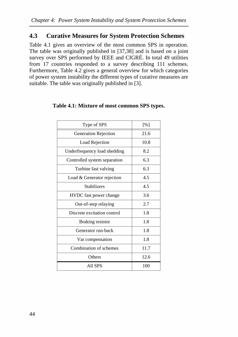
Chapter 4: Power System Instability and System Protection Schemes
4.3 Curative Measures for System Protection SchemesTable 4.1 gives an overview of the most common SPS in operation.The table was originally published in [37,38] and is based on a jointsurvey over SPS performed by IEEE and CIGRÉ. In total 49 utilitiesfrom 17 countries responded to a survey describing 111 schemes.Furthermore, Table 4.2 gives a general overview for which categoriesof power system instability the different types of curative measures aresuitable. The table was originally published in [3].
Table 4.1: Mixture of most common SPS types.
Type of SPS [%]
Generation Rejection 21.6
Load Rejection 10.8
Underfrequency load shedding 8.2
Controlled system separation 6.3
Turbine fast valving 6.3
Load & Generator rejection 4.5
Stabilizers 4.5
HVDC fast power change 3.6
Out-of-step relaying 2.7
Discrete excitation control 1.8
Braking resistor 1.8
Generator run-back 1.8
Var compensation 1.8
Combination of schemes 11.7
Others 12.6
All SPS 100
44
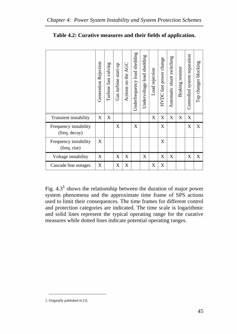
Chapter 4: Power System Instability and System Protection Schemes
Table 4.2: Curative measures and their fields of application.
Fig. 4.31 shows the relationship between the duration of major powersystem phenomena and the approximate time frame of SPS actionsused to limit their consequences. The time frames for different controland protection categories are indicated. The time scale is logarithmicand solid lines represent the typical operating range for the curativemeasures while dotted lines indicate potential operating ranges.
Gen
erat
ion
Rej
ectio
n
Tur
bine
fas
t val
ving
Gas
turb
ine
star
t-up
Act
ions
on
the
AG
C
Und
erfr
eque
ncy
load
she
ddin
g
Und
ervo
ltage
load
she
ddin
g
Loa
d re
ject
ion
HV
DC
fas
t pow
er c
hang
e
Aut
omat
ic s
hunt
sw
itchi
ng
Bra
king
res
isto
r
Con
trol
led
syst
em s
epar
atio
n
Tap
cha
nger
blo
ckin
g
Transient instability X X X X X X X
Frequency instability (freq. decay)
X X X X X
Frequency instability (freq. rise)
X X
Voltage instability X X X X X X X X
Cascade line outages X X X X X
1. Originally published in [3].
45
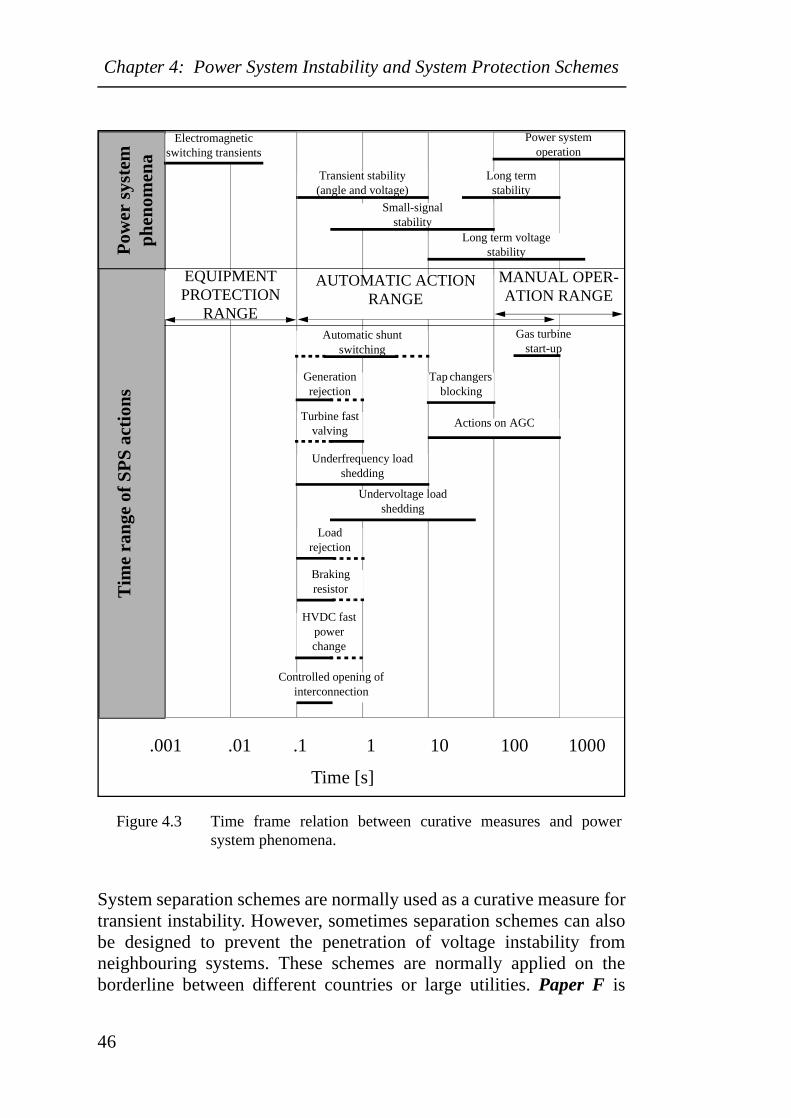
Chapter 4: Power System Instability and System Protection Schemes
Figure 4.3 Time frame relation between curative measures and powersystem phenomena.
System separation schemes are normally used as a curative measure fortransient instability. However, sometimes separation schemes can alsobe designed to prevent the penetration of voltage instability fromneighbouring systems. These schemes are normally applied on theborderline between different countries or large utilities. Paper F is
Tim
e ra
nge
of S
PS
acti
ons
Pow
er s
yste
mph
enom
ena
.001 .01 .1 1 10 100 1000
Time [s]
Transient stability(angle and voltage)
Long termstability
Power systemoperation
Small-signal stability
Long term voltagestability
AUTOMATIC ACTIONRANGE
MANUAL OPER-ATION RANGE
EQUIPMENTPROTECTION
RANGEGas turbine
start-upAutomatic shunt
switching
Generationrejection
Turbine fast valving
Tap changers blocking
Actions on AGC
Underfrequency loadshedding
Undervoltage loadshedding
Loadrejection
Brakingresistor
HVDC fast power change
Controlled opening ofinterconnection
Electromagneticswitching transients
46
Chapter 4: Power System Instability and System Protection Schemes
introducing a similar scheme but instead of invoking large systemregions the aim of this scheme is to secure voltage stability in at leastone part of the system in order to avoid a black start. The scheme isusing conventional distance protection and should operate when acomplete breakdown cannot be obstructed by any other means.
4.4 System Protection Schemes in the Nordel SystemSPS in the Nordel system will be treated here. An extensive survey onSPS and field experience worldwide is given in [159].
The instantaneous emergency reserve in the Nordel system isequivalent to the loss of the largest unit in service; normally about1200 MW. In addition SPS are used for extreme contingencies such assevere grid weakening or a loss of generation exceeding the largestunit. There are a number of SPS operating in the Nordel system today,addressing all different types of power system instability, involvinglarge and small areas. Examples are active power support fromneighbouring regions via HVDC links, automatic conversion frompure reactive generation to active generation for some hydro units,automatic start of gas turbines, load shedding or system separation. Toavoid overload or instability in case of reduced transfer capacity incritical intersections generator shedding is applied. The HVDC supportis activated in case of low frequency and/or low voltage in the HVDCstation or low voltage in a remote station. A number of EmergencyPower Control steps are implemented in the control systems of thelinks. There are different setting possibilities but the most commonway to control the power flow is to apply a number of time-delayedstep-changes e.g ∆P=50 MW with a 2 s time delay. Automaticfrequency controlled start of gas-turbines is used to some extent withinthe Nordel system. In Sweden these units are started at 49.5 Hz. Non-discriminative UFLS is used as a final curative measure in case ofextreme loss of generation. The UFLS is divided into five steps whereeach step has two different time delays.
Fig. 4.4 gives an overview of the main corrective measures used tocounteract the different types of power system instability in the Nordelsystem. The grey window represents the emergency reserve togetherwith on-line hydro units. The emergency reserve is divided intoinstantaneous-, fast- and slow reserves. The emergency reserve isintended to counter frequency decays down to 49.5 Hz. In case the
47
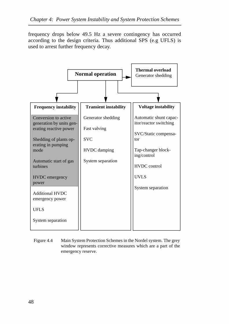
Chapter 4: Power System Instability and System Protection Schemes
frequency drops below 49.5 Hz a severe contingency has occurredaccording to the design criteria. Thus additional SPS (e.g UFLS) isused to arrest further frequency decay.
Figure 4.4 Main System Protection Schemes in the Nordel system. The greywindow represents corrective measures which are a part of theemergency reserve.
Normal operationThermal overloadGenerator shedding
Frequency instability
Conversion to active generation by units gen-erating reactive power
Shedding of plants op-erating in pumping mode
Automatic start of gas turbines
HVDC emergency power
Additional HVDC emergency power
UFLS
System separation
Transient instability
Generator shedding
Fast valving
SVC
HVDC damping
System separation
Voltage instability
Automatic shunt capac-itor/reactor switching
SVC/Static compensa-tor
Tap-changer block-ing/control
HVDC control
UVLS
System separation
48
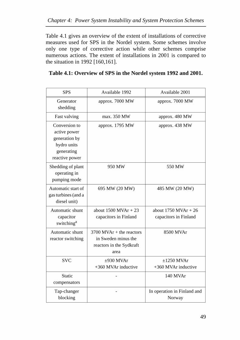
Chapter 4: Power System Instability and System Protection Schemes
Table 4.1 gives an overview of the extent of installations of correctivemeasures used for SPS in the Nordel system. Some schemes involveonly one type of corrective action while other schemes comprisenumerous actions. The extent of installations in 2001 is compared tothe situation in 1992 [160,161].
Table 4.1: Overview of SPS in the Nordel system 1992 and 2001.
SPS Available 1992 Available 2001
Generator shedding
approx. 7000 MW approx. 7000 MW
Fast valving max. 350 MW approx. 480 MW
Conversion to active power generation by hydro units generating
reactive power
approx. 1795 MW approx. 438 MW
Shedding of plant operating in
pumping mode
950 MW 550 MW
Automatic start of gas turbines (and a
diesel unit)
695 MW (20 MW) 485 MW (20 MW)
Automatic shunt capacitor
switchinga
about 1500 MVAr + 23 capacitors in Finland
about 1750 MVAr + 26 capacitors in Finland
Automatic shunt reactor switching
3700 MVAr + the reactors in Sweden minus the
reactors in the Sydkraft area
8500 MVAr
SVC ±930 MVAr+360 MVAr inductive
±1250 MVAr+360 MVAr inductive
Static compensators
- 140 MVAr
Tap-changer blocking
- In operation in Finland and Norway
49
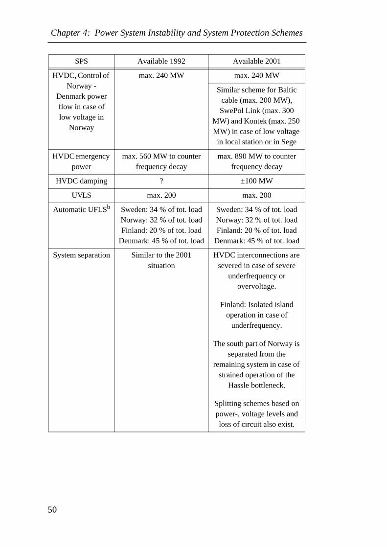
Chapter 4: Power System Instability and System Protection Schemes
HVDC, Control of Norway -
Denmark power flow in case of low voltage in
Norway
max. 240 MW max. 240 MW
Similar scheme for Baltic cable (max. 200 MW), SwePol Link (max. 300
MW) and Kontek (max. 250 MW) in case of low voltage in local station or in Sege
HVDC emergency power
max. 560 MW to counter frequency decay
max. 890 MW to counter frequency decay
HVDC damping ? ±100 MW
UVLS max. 200 max. 200
Automatic UFLSb Sweden: 34 % of tot. loadNorway: 32 % of tot. loadFinland: 20 % of tot. load
Denmark: 45 % of tot. load
Sweden: 34 % of tot. loadNorway: 32 % of tot. loadFinland: 20 % of tot. load
Denmark: 45 % of tot. load
System separation Similar to the 2001 situation
HVDC interconnections are severed in case of severe
underfrequency or overvoltage.
Finland: Isolated island operation in case of
underfrequency.
The south part of Norway is separated from the
remaining system in case of strained operation of the
Hassle bottleneck.
Splitting schemes based on power-, voltage levels and loss of circuit also exist.
SPS Available 1992 Available 2001
50
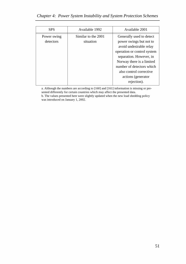
Chapter 4: Power System Instability and System Protection Schemes
Power swing detectors
Similar to the 2001 situation
Generally used to detect power swings but not to avoid undesirable relay
operation or control system separation. However, in
Norway there is a limited number of detectors which
also control corrective actions (generator
rejection).
a. Although the numbers are according to [160] and [161] information is missing or pre-sented differently for certain countries which may affect the presented data.b. The values presented here were slightly updated when the new load shedding policy was introduced on January 1, 2002.
SPS Available 1992 Available 2001
51
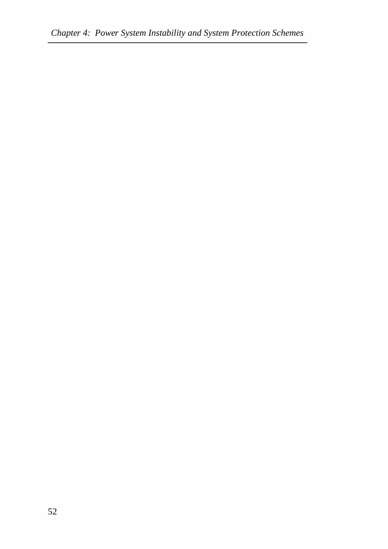
Chapter 4: Power System Instability and System Protection Schemes
52
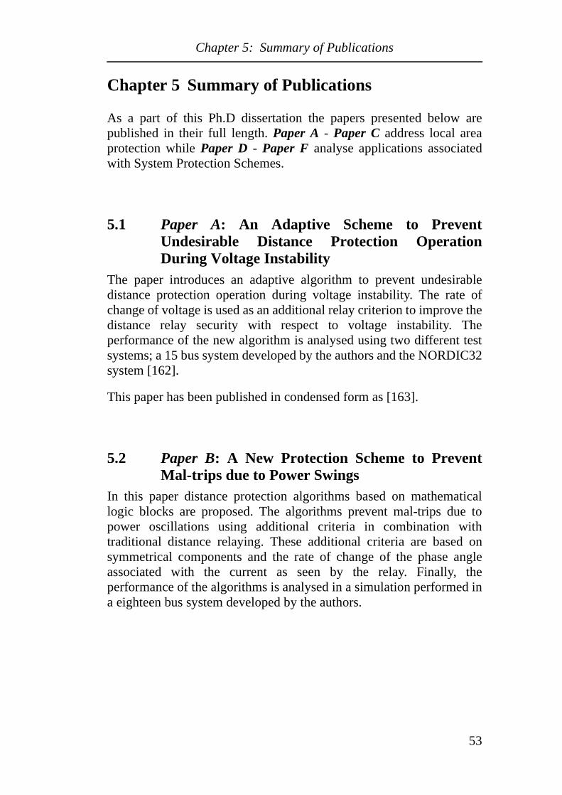
Chapter 5: Summary of Publications
Chapter 5 Summary of Publications
As a part of this Ph.D dissertation the papers presented below arepublished in their full length. Paper A - Paper C address local areaprotection while Paper D - Paper F analyse applications associatedwith System Protection Schemes.
5.1 Paper A: An Adaptive Scheme to PreventUndesirable Distance Protection OperationDuring Voltage Instability
The paper introduces an adaptive algorithm to prevent undesirabledistance protection operation during voltage instability. The rate ofchange of voltage is used as an additional relay criterion to improve thedistance relay security with respect to voltage instability. Theperformance of the new algorithm is analysed using two different testsystems; a 15 bus system developed by the authors and the NORDIC32system [162].
This paper has been published in condensed form as [163].
5.2 Paper B: A New Protection Scheme to PreventMal-trips due to Power Swings
In this paper distance protection algorithms based on mathematicallogic blocks are proposed. The algorithms prevent mal-trips due topower oscillations using additional criteria in combination withtraditional distance relaying. These additional criteria are based onsymmetrical components and the rate of change of the phase angleassociated with the current as seen by the relay. Finally, theperformance of the algorithms is analysed in a simulation performed ina eighteen bus system developed by the authors.
53
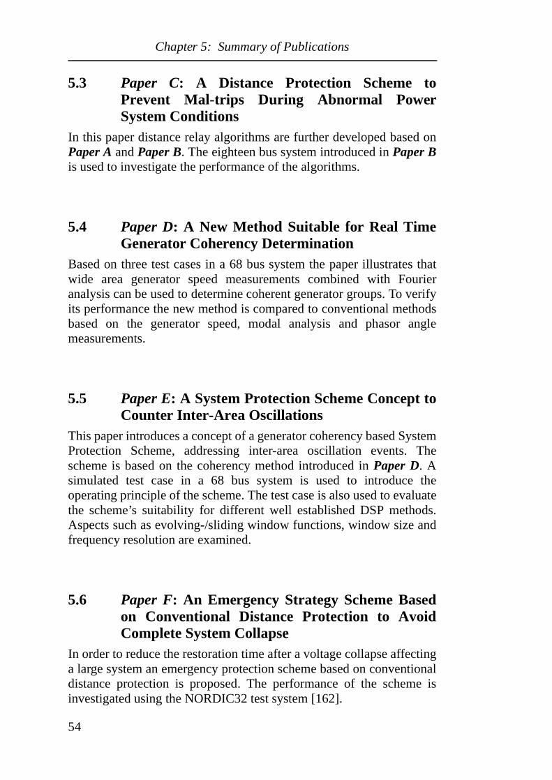
Chapter 5: Summary of Publications
5.3 Paper C: A Distance Protection Scheme toPrevent Mal-trips During Abnormal PowerSystem Conditions
In this paper distance relay algorithms are further developed based onPaper A and Paper B. The eighteen bus system introduced in Paper Bis used to investigate the performance of the algorithms.
5.4 Paper D: A New Method Suitable for Real TimeGenerator Coherency Determination
Based on three test cases in a 68 bus system the paper illustrates thatwide area generator speed measurements combined with Fourieranalysis can be used to determine coherent generator groups. To verifyits performance the new method is compared to conventional methodsbased on the generator speed, modal analysis and phasor anglemeasurements.
5.5 Paper E: A System Protection Scheme Concept toCounter Inter-Area Oscillations
This paper introduces a concept of a generator coherency based SystemProtection Scheme, addressing inter-area oscillation events. Thescheme is based on the coherency method introduced in Paper D. Asimulated test case in a 68 bus system is used to introduce theoperating principle of the scheme. The test case is also used to evaluatethe scheme’s suitability for different well established DSP methods.Aspects such as evolving-/sliding window functions, window size andfrequency resolution are examined.
5.6 Paper F: An Emergency Strategy Scheme Basedon Conventional Distance Protection to AvoidComplete System Collapse
In order to reduce the restoration time after a voltage collapse affectinga large system an emergency protection scheme based on conventionaldistance protection is proposed. The performance of the scheme isinvestigated using the NORDIC32 test system [162].
54
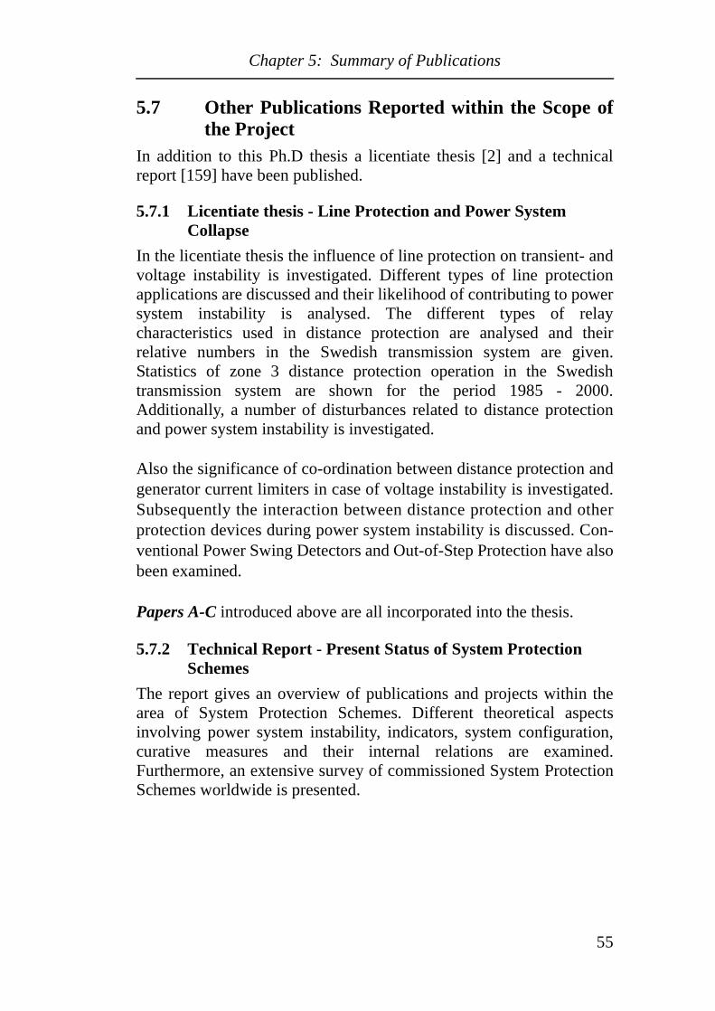
Chapter 5: Summary of Publications
5.7 Other Publications Reported within the Scope ofthe Project
In addition to this Ph.D thesis a licentiate thesis [2] and a technicalreport [159] have been published.
5.7.1 Licentiate thesis - Line Protection and Power System Collapse
In the licentiate thesis the influence of line protection on transient- andvoltage instability is investigated. Different types of line protectionapplications are discussed and their likelihood of contributing to powersystem instability is analysed. The different types of relaycharacteristics used in distance protection are analysed and theirrelative numbers in the Swedish transmission system are given.Statistics of zone 3 distance protection operation in the Swedishtransmission system are shown for the period 1985 - 2000.Additionally, a number of disturbances related to distance protectionand power system instability is investigated.
Also the significance of co-ordination between distance protection andgenerator current limiters in case of voltage instability is investigated.Subsequently the interaction between distance protection and otherprotection devices during power system instability is discussed. Con-ventional Power Swing Detectors and Out-of-Step Protection have alsobeen examined.
Papers A-C introduced above are all incorporated into the thesis.
5.7.2 Technical Report - Present Status of System Protection Schemes
The report gives an overview of publications and projects within thearea of System Protection Schemes. Different theoretical aspectsinvolving power system instability, indicators, system configuration,curative measures and their internal relations are examined.Furthermore, an extensive survey of commissioned System ProtectionSchemes worldwide is presented.
55

Chapter 5: Summary of Publications
56
Chapter 6: Conclusions and Future Work
Chapter 6 Conclusions and Future Work
6.1 ConclusionsThis thesis introduces new methods to improve the performance ofpower system protection in case of system instability. The methods areprimarily designed to mitigate power system breakdown.
Distance protection may contribute to power system instability.Measures to improve its performance have been proposed using newrelay criteria combined with conventional impedance characteristics.In case of voltage instability the criteria are based on the derivative ofthe voltage whereas the rate of change of the phase angle of the currentis used for transient instability. The measures improve the relaysecurity with respect to voltage instability whereas the reach of thedistance protection is unrestricted. Line length, different swingfrequencies or faults having a slowly decreasing impedance will notaffect the performance and availability of the proposed schemes, whichmay be the case for conventional Power Swing Detectors.Furthermore, fault clearing will not be blocked as in the case ofconventional PSD applications.
A high degree of security is relevant today as the trend implies thatutilities are subjected to penalty fees in the case of undelivered energy.Companies therefore want to avoid undesirable relay tripping indeed.The methods proposed here are based on mathematical logic blockswhich are easily adapted to numerical relays.
In the Swedish bulk power system the number of power oscillationshas increased significantly during recent years. To dampen oscillationsa well established generator coherency is often required. In this thesis amethod based on wide area generator speed measurements and Fourieranalysis is proposed for the purpose of on-line coherency tracking. Theperformance of the new method has been evaluated by comparing thegenerator coherency obtained from the new method with coherenciesobtained from conventional methods based on generator speed, modalanalysis and phasor angle measurements. The new method and the off-line methods based on generator speed and modal analysis give almostidentical results, however the results obtained from phasormeasurements show deviations. This is particularly interesting as thegenerator angle probably is the most common on-line indicator for
57
Chapter 6: Conclusions and Future Work
generator coherency determination. Furthermore, taking the transientdistortion immediately after a disturbance into account, this workindicates that the method introduced here generates a reliablecoherency considerably quicker than the methods based on pure speedor generator voltage angle measurements.
Using a method based on speed measurement combined with Fourieranalysis a concept for a System Protection Scheme addressing inter-area events is proposed. Different Digital Signal Processing issuessuch as window functions, time-frequency resolution and signalanalysis methods have been investigated. Based on these investigationsa scheme was designed. For the detection of inter-area modes,parametric methods are the most feasible. Evolving window functionsgenerally detect the main mode somewhat faster than sliding windows.However, evolving windows require a trigger activated by the presenceof an inter-area mode. This trigger may complicate the design of thescheme and therefore the design proposed here is based on a slidingwindow. To shorten the detection time of the main mode, a reducedfrequency resolution can be applied. However, a lower frequencyresolution contributes to spectral mode shifts and reduces the quality ofthe estimate of the instantaneous speed deviation. As a result thediscrimination of the unstable/stable nature of the modes is of a lowerquality. Also the phase estimation deteriorates which in turn leads to aless reliable generator coherency determination. The design proposedhere is therefore based on a high frequency resolution, accepting asomewhat slower response.
Finally, an emergency scheme is proposed utilising conventionaldistance relays to avoid a complete system collapse in case of severevoltage instability. The purpose of the scheme is to co-ordinate alldistance relays belonging to a transfer section so they willsimultaneously operate due to the voltage instability. As a result a partof the system can be saved from the collapse, black-start can beavoided and the restoration time can be reduced. Furthermore, in caselong distance communication is introduced the scheme can be utilizedfor the supervision of corrective measures such as generator or loadshedding.
58
Chapter 6: Conclusions and Future Work
6.2 Future WorkFuture work directly linked to the work in this thesis includes variouspractical issues related to the realization of the proposed applications.For the distance relay algorithms emphasising security, issues such asdata memory, window size and data filtering must be furtherinvestigated. To obtain reliable operation well defined settingprocedures for the new relay criteria should also be developed.
The System Protection Scheme based on speed measurements andFourier Analysis is still at an early stage of development. An adaptivefrequency resolution for the detection process could be used to furtherimprove the performance of the scheme. Also the main mode trackingsystems could be based on a combination of evolving and slidingwindow functions.
A future approach could be the use of extensive protection systemswhere equipment protection and System Protection Schemes areclosely related to each other. As communicative relays become morewidely used a large amount of data is available and the number ofpossible remedial actions increases significantly. These features areattractive for SPS. At the same time the wide area data acquisition usedto control the actions associated with the SPS, can also be used toprevent incorrect equipment protection performance, as theiralgorithms can be based on wide area data. Possible research topics arethe optimal utilization of the extensive data with respect to relayalgorithms and the detection and counteraction of different powersystem phenomena. Also the optimal co-ordination between local andsystem wide protection applications with respect to dependability andsecurity should be investigated.
Traditionally measures taken by System Protection Schemes have beenextensive. The schemes have not been adjusted to each specificdisturbance and sometimes the overstated curative measures haveresulted in needless social inconvenience and unnecessary largedisturbance cost. Another aspect is the relation between operatingsafety limits and the (real-time) prevailing operating conditions wherethe remedial measures represent one feature. To utilize the system (atevery single moment) to its maximum capacity a continuousoptimization must be performed with respect to all parameters wherealso the remedial actions should be adjusted based on the actual systemcondition. There are therefore major incentives for more accurate andintelligent (adaptive) applications controlling the corrective measures.
59
Chapter 6: Conclusions and Future Work
One interesting tool for this purpose is GPS synchronized wide areameasurements where the system status is provided in real-time. Thisfeature combined with for example Artificial Intelligence could be afruitful area.
As computers become faster more sophisticated DSP methods can beused for protection applications. Traditionally the measured relaysignals have been processed based on DSP techniques, and then theelectrical quantities associated with the signals have been used as relaycriteria. However, the present situation makes it interesting to searchfor new relay criteria based on inherent DSP parameters. Typically thecriteria could be an intermediate quantity obtained from the DSPprocess during the evaluation of the electrical signal.
An observation made during the project is the importance of accurateprotection modelling during simulation based studies. Anotherobservation is the influence of numerical defects during simulationsclose to instability. An ever lasting important task is to further developsimulations tools, both with respect to numerical and modellingaspects.
A result of the more extensive use of communication in power systemprotection are the increased requirements of data security. Overall thisis a very relevant topic involving numerous aspects of power systemoperation. The topic offers many challenges within a broad range ofdifferent research areas.
60
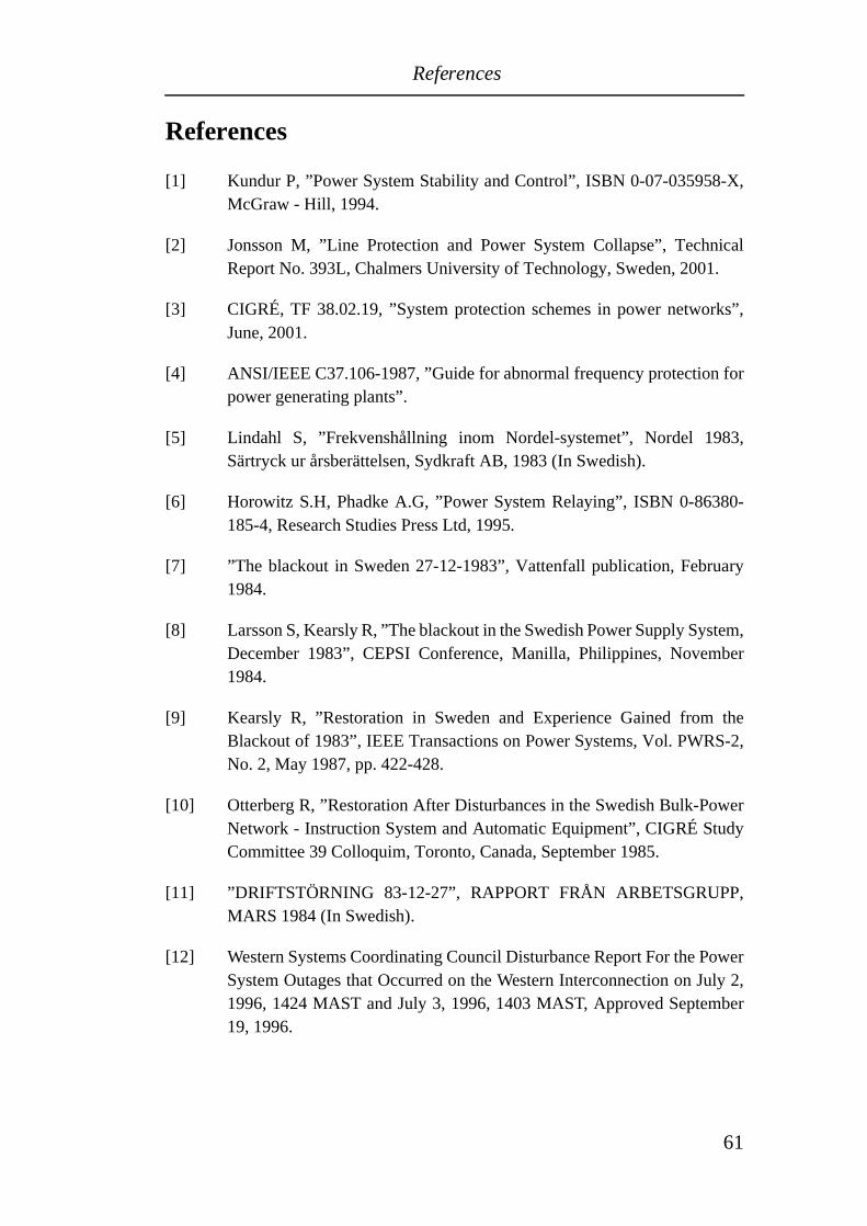
References
References
[1] Kundur P, ”Power System Stability and Control”, ISBN 0-07-035958-X,McGraw - Hill, 1994.
[2] Jonsson M, ”Line Protection and Power System Collapse”, TechnicalReport No. 393L, Chalmers University of Technology, Sweden, 2001.
[3] CIGRÉ, TF 38.02.19, ”System protection schemes in power networks”,June, 2001.
[4] ANSI/IEEE C37.106-1987, ”Guide for abnormal frequency protection forpower generating plants”.
[5] Lindahl S, ”Frekvenshållning inom Nordel-systemet”, Nordel 1983,Särtryck ur årsberättelsen, Sydkraft AB, 1983 (In Swedish).
[6] Horowitz S.H, Phadke A.G, ”Power System Relaying”, ISBN 0-86380-185-4, Research Studies Press Ltd, 1995.
[7] ”The blackout in Sweden 27-12-1983”, Vattenfall publication, February1984.
[8] Larsson S, Kearsly R, ”The blackout in the Swedish Power Supply System,December 1983”, CEPSI Conference, Manilla, Philippines, November1984.
[9] Kearsly R, ”Restoration in Sweden and Experience Gained from theBlackout of 1983”, IEEE Transactions on Power Systems, Vol. PWRS-2,No. 2, May 1987, pp. 422-428.
[10] Otterberg R, ”Restoration After Disturbances in the Swedish Bulk-PowerNetwork - Instruction System and Automatic Equipment”, CIGRÉ StudyCommittee 39 Colloquim, Toronto, Canada, September 1985.
[11] ”DRIFTSTÖRNING 83-12-27”, RAPPORT FRÅN ARBETSGRUPP,MARS 1984 (In Swedish).
[12] Western Systems Coordinating Council Disturbance Report For the PowerSystem Outages that Occurred on the Western Interconnection on July 2,1996, 1424 MAST and July 3, 1996, 1403 MAST, Approved September19, 1996.
61
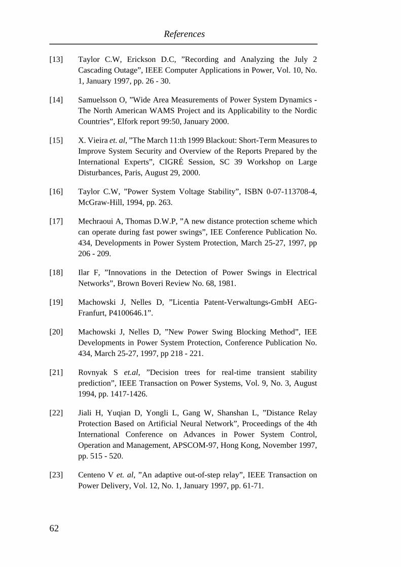
References
[13] Taylor C.W, Erickson D.C, ”Recording and Analyzing the July 2Cascading Outage”, IEEE Computer Applications in Power, Vol. 10, No.1, January 1997, pp. 26 - 30.
[14] Samuelsson O, ”Wide Area Measurements of Power System Dynamics -The North American WAMS Project and its Applicability to the NordicCountries”, Elfork report 99:50, January 2000.
[15] X. Vieira et. al, ”The March 11:th 1999 Blackout: Short-Term Measures toImprove System Security and Overview of the Reports Prepared by theInternational Experts”, CIGRÉ Session, SC 39 Workshop on LargeDisturbances, Paris, August 29, 2000.
[16] Taylor C.W, ”Power System Voltage Stability”, ISBN 0-07-113708-4,McGraw-Hill, 1994, pp. 263.
[17] Mechraoui A, Thomas D.W.P, ”A new distance protection scheme whichcan operate during fast power swings”, IEE Conference Publication No.434, Developments in Power System Protection, March 25-27, 1997, pp206 - 209.
[18] Ilar F, ”Innovations in the Detection of Power Swings in ElectricalNetworks”, Brown Boveri Review No. 68, 1981.
[19] Machowski J, Nelles D, ”Licentia Patent-Verwaltungs-GmbH AEG-Franfurt, P4100646.1”.
[20] Machowski J, Nelles D, ”New Power Swing Blocking Method”, IEEDevelopments in Power System Protection, Conference Publication No.434, March 25-27, 1997, pp 218 - 221.
[21] Rovnyak S et.al, ”Decision trees for real-time transient stabilityprediction”, IEEE Transaction on Power Systems, Vol. 9, No. 3, August1994, pp. 1417-1426.
[22] Jiali H, Yuqian D, Yongli L, Gang W, Shanshan L, ”Distance RelayProtection Based on Artificial Neural Network”, Proceedings of the 4thInternational Conference on Advances in Power System Control,Operation and Management, APSCOM-97, Hong Kong, November 1997,pp. 515 - 520.
[23] Centeno V et. al, ”An adaptive out-of-step relay”, IEEE Transaction onPower Delivery, Vol. 12, No. 1, January 1997, pp. 61-71.
62
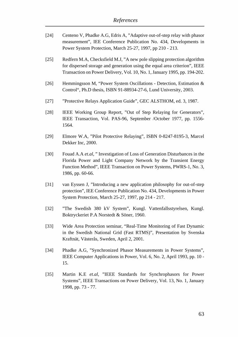
References
[24] Centeno V, Phadke A.G, Edris A, ”Adaptive out-of-step relay with phasormeasurement”, IEE Conference Publication No. 434, Developments inPower System Protection, March 25-27, 1997, pp 210 - 213.
[25] Redfern M.A, Checksfield M.J, ”A new pole slipping protection algorithmfor dispersed storage and generation using the equal area criterion”, IEEETransaction on Power Delivery, Vol. 10, No. 1, January 1995, pp. 194-202.
[26] Hemmingsson M, “Power System Oscillations - Detection, Estimation &Control“, Ph.D thesis, ISBN 91-88934-27-6, Lund University, 2003.
[27] ”Protective Relays Application Guide”, GEC ALSTHOM, ed. 3, 1987.
[28] IEEE Working Group Report, ”Out of Step Relaying for Generators”,IEEE Transaction, Vol. PAS-96, September /October 1977, pp. 1556-1564.
[29] Elmore W.A, ”Pilot Protective Relaying”, ISBN 0-8247-8195-3, MarcelDekker Inc, 2000.
[30] Fouad A.A et.al, ” Investigation of Loss of Generation Disturbances in theFlorida Power and Light Company Network by the Transient EnergyFunction Method”, IEEE Transaction on Power Systems, PWRS-1, No. 3,1986, pp. 60-66.
[31] van Eyssen J, ”Introducing a new application philosophy for out-of-stepprotection”, IEE Conference Publication No. 434, Developments in PowerSystem Protection, March 25-27, 1997, pp 214 - 217.
[32] ”The Swedish 380 kV System”, Kungl. Vattenfallsstyrelsen, Kungl.Boktryckeriet P.A Norstedt & Söner, 1960.
[33] Wide Area Protection seminar, “Real-Time Monitoring of Fast Dynamicin the Swedish National Grid (Fast RTMS)”, Presentation by SvenskaKraftnät, Västerås, Sweden, April 2, 2001.
[34] Phadke A.G, ”Synchronized Phasor Measurements in Power Systems”,IEEE Computer Applications in Power, Vol. 6, No. 2, April 1993, pp. 10 -15.
[35] Martin K.E et.al, ”IEEE Standards for Synchrophasors for PowerSystems”, IEEE Transactions on Power Delivery, Vol. 13, No. 1, January1998, pp. 73 - 77.
63
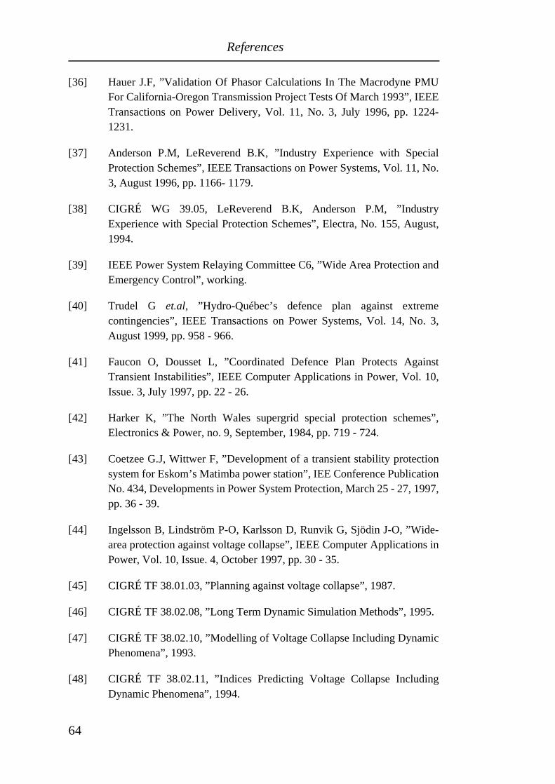
References
[36] Hauer J.F, ”Validation Of Phasor Calculations In The Macrodyne PMUFor California-Oregon Transmission Project Tests Of March 1993”, IEEETransactions on Power Delivery, Vol. 11, No. 3, July 1996, pp. 1224-1231.
[37] Anderson P.M, LeReverend B.K, ”Industry Experience with SpecialProtection Schemes”, IEEE Transactions on Power Systems, Vol. 11, No.3, August 1996, pp. 1166- 1179.
[38] CIGRÉ WG 39.05, LeReverend B.K, Anderson P.M, ”IndustryExperience with Special Protection Schemes”, Electra, No. 155, August,1994.
[39] IEEE Power System Relaying Committee C6, ”Wide Area Protection andEmergency Control”, working.
[40] Trudel G et.al, ”Hydro-Québec’s defence plan against extremecontingencies”, IEEE Transactions on Power Systems, Vol. 14, No. 3,August 1999, pp. 958 - 966.
[41] Faucon O, Dousset L, ”Coordinated Defence Plan Protects AgainstTransient Instabilities”, IEEE Computer Applications in Power, Vol. 10,Issue. 3, July 1997, pp. 22 - 26.
[42] Harker K, ”The North Wales supergrid special protection schemes”,Electronics & Power, no. 9, September, 1984, pp. 719 - 724.
[43] Coetzee G.J, Wittwer F, ”Development of a transient stability protectionsystem for Eskom’s Matimba power station”, IEE Conference PublicationNo. 434, Developments in Power System Protection, March 25 - 27, 1997,pp. 36 - 39.
[44] Ingelsson B, Lindström P-O, Karlsson D, Runvik G, Sjödin J-O, ”Wide-area protection against voltage collapse”, IEEE Computer Applications inPower, Vol. 10, Issue. 4, October 1997, pp. 30 - 35.
[45] CIGRÉ TF 38.01.03, ”Planning against voltage collapse”, 1987.
[46] CIGRÉ TF 38.02.08, ”Long Term Dynamic Simulation Methods”, 1995.
[47] CIGRÉ TF 38.02.10, ”Modelling of Voltage Collapse Including DynamicPhenomena”, 1993.
[48] CIGRÉ TF 38.02.11, ”Indices Predicting Voltage Collapse IncludingDynamic Phenomena”, 1994.
64
References
[49] CIGRÉ TF 38.02.12, ”Criteria and Countermeasures for VoltageCollapse”, 1995.
[50] CIGRÉ TF 38.01.07, ”Control of Power System Oscillations”, 1996.
[51] CIGRÉ WG 34.08, ”Protection against Voltage Collapse”, No. 128,August, 1998.
[52] CIGRÉ TF 38.02.14, ”Analysis and Modelling Needs of Power Systemsunder Major Frequency Disturbances”, 1999.
[53] CIGRÉ TF 38.02.17, ”Advanced Angle Stability Controls”, 1999.
[54] IEEE Power System Relaying Committee K12, ”System Protection andVoltage Stability”, 1993.
[55] IEEE Power System Relaying Committee K12, ”Voltage CollapseMitigation”, 1997.
[56] IEEE Power System Relaying Committee C6, ”Performance of GeneratorProtection During Major System Disturbances”, working.
[57] Ajjarapu V, Feng Z, ”A novel approach for voltage collapse analysis andcontrol”, Proceedings of PowerCon, 1998, pp. 1499 - 1503.
[58] Fischl R, Mercede F, ”Can Voltage Security Indices Predict VoltageCollapse Problems in Large-Scale Power Networks”, Proceedings of IEEEInternational Symposium on Circuit and Systems, 1988, pp.665 - 668.
[59] Fischl R et.al, ”A comparison of indices for predicting voltage collapse inpower systems”, Proceedings of the 27th Conference on Decision andControl, Austin, Texas, USA, December, 1988.
[60] Ejebe G.C et.al, ”On-Line Voltage Stability Assessment: Framework andImplementation”, Proceedings of IEEE PES Winter meeting, Tampa,Florida, USA, 1998.
[61] Dobson I et.al, “Voltage Collapse in Power Systems”, IEEE Circuit andDevices Magazine, Vol. 8, Issue. 3, May 1992, pp. 40 - 45.
[62] Evers T.A et.al, “Prediction of Voltage Collapse in Power Systems”,Proceedings of the Thirtieth Southeastern Symposium on System Theory,1998, pp. 354 - 358.
65
References
[63] Greene S et.al, ”Sensitivity of the load margin to voltage collapse withrespect to arbitrary parameters”, IEEE Transactions on Power Systems,Vol. 12, No. 1, February 1997, pp. 262 - 272.
[64] Sam D et.al, “Local Severity Indices and Alarm Processing for Small ScalePower Systems”, Proceedings of the American Control Conference,Arlington, USA, June 25 - 27, 2001.
[65] Crow M.L, Lesieutre B.C, “Voltage collapse”, IEEE Potentials, Vol. 13,No.2, April 1994, pp. 18 - 21.
[66] Kulkarni S.S et.al, ”New perceptions in integrated power system operationand control”, Proceedings of IEEE Region 10 International Conference onGlobal Connectivity in Energy, Computer, Communication and Control,1998, pp. 489 - 496.
[67] Yabe K et.al, ”Conceptual Designs of AI-based Systems for LocalPrediction of Voltage Collapse”, IEEE Transactions on Power Systems,Vol. 11, No. 1, February 1996, pp. 137 - 145.
[68] Momoh J.A, Zhang Y, ”Voltage Stability Estimation”, Proceedings ofIEEE International Conference on Systems, Man and Cybernetics, 1990,pp. 94 - 97.
[69] Begovic M.M, Phadke A.G, ”Voltage stability assessment throughmeasurement of a reduced state vector”, IEEE Transactions on PowerSystems, Vol. 5, No. 1, February 1990, pp. 198 - 203.
[70] Chiang H-D, René J-J, ”Toward a Practical Performance Index forPredicting Voltage Collapse in Electric Power Systems”, IEEETransactions on Power Systems, Vol. 10, No. 2, May 1995, pp. 584- 592.
[71] Canizares C.A et.al, ”Comparison of Performance Indices for Detection ofProximity to Voltage Collapse”, IEEE Transactions on Power Systems,Vol. 11, No. 3, August 1996, pp. 1441 - 1450.
[72] Madan S, Bollinger K.E, ”Artificial Intelligence Assisted Voltage StabilityEnhancement”, Proceedings of Canadian Conference on Electrical andComputer Engineering, 1996, pp. 392 - 395.
[73] De Angelis G et.al, ”Transient voltage stability signature in time domainsimulations”, Proceedings of MELECON 8th MediterraneanElectrotechnical Conference, 1996, pp. 859 - 862.
66
References
[74] Löf P.A et.al, ”Fast calculation of a voltage stability index”, IEEETransactions on Power Systems, Vol. 7, No. 1, February 1992, pp. 54 - 64.
[75] Tamura Y et.al, ”Voltage Instability Proximity Index (VIPI) Based onMultiple Load Flow Solutions in Ill-conditioned Power Systems”,Proceedings of the 27th Conference on Decision and Control, Austin,Texas, USA, December, 1988.
[76] Tamura Y et.al, ”Relationship between voltage instability and multipleload flow solutions in electric power systems”, IEEE Transactions onPower Apparatus and Systems, Vol. 102, No. 5, May 1983, pp. 1115 -1125.
[77] Vu K et.al, ”Use of Local Measurement to Estimate Voltage-StabilityMargin”, IEEE Transactions on Power Systems, Vol. 14, No. 3, August1999, pp. 1029- 1035.
[78] Vu K et.al, ”Voltage Instability Predictor (VIP) and Its Applications”,Proceedings of PSCC 99 Conference, June, 1999.
[79] Vu K et.al, ”Grids Get Smart Protection and Control”, IEEE ComputerApplications in Power, October, 1997.
[80] Julian D.E et.al, ”Quantifying Proximity To Voltage Collapse Using TheVoltage Instability Predictor (VIP)”, Proceedings of IEEE PowerEngineering Society Summer Meeting, 2000, pp. 931 - 936.
[81] Moghavvemi M, Omar F.M, ”Technique for contingency monitoring andvoltage collapse prediction”, IEE Proceedings on Generation,Transmission and Distribution, Vol. 145, No. 6, November 1998, pp. 634- 640.
[82] Moghavvemi M, Omar F.M, ”A Line Outage Study for Prediction of StaticVoltage Collapse”, IEEE Power Engineering Review, Vol. 18, No. 7, July1998, pp. 52- 54.
[83] Moghavvemi M, Faruque M.O, ”Estimation of Voltage Collapse fromLocal Measurement of Line Power Flow and Bus Voltages”, Proceedingsof International Conference on Electric Power Engineering (PowerTech).Budapest, 1999, pp. 77.
[84] Chiang H-D et.al, ”On voltage collapse in electric power systems”,Proceedings of Power Industry Computer Application Conference (PICA),1989, pp. 342 - 349.
67
References
[85] Chiang H-D et.al, ”On voltage collapse in electric power systems”, IEEETransactions on Power Systems, Vol. 5, No. 2, May 1990, pp. 601 - 611.
[86] Jasmon G.B et.al, ”Prediction of voltage collapse in power systems usinga reduced system model”, International Conference on Control, 1991, pp.32 - 36.
[87] Marceau R.J et.al, ”Fourier methods for estimating power system stabilitylimits”, Proceedings of the Power Industry Computer ApplicationConference, 1993, pp. 418 - 425.
[88] Marceau R.J et.al, ”Fourier methods for estimating power system stabilitylimits”, IEEE Transactions on Power Systems, Vol. 9, No. 2, May 1994,pp. 764 - 771.
[89] DeMarco C.L, Overbye T.J, ”An energy based security measure forassessing vulnerability to voltage collapse”, IEEE Transactions on PowerSystems, Vol. 5, No. 2, May 1990, pp. 419 - 427.
[90] Overbye T.J et.al, ”A composite framework for synchronous and voltagestability in power systems”, Proceedings of IEEE InternationalSymposium on Circuit and Systems, 1992, pp. 2541 - 2544.
[91] Gubina F, Strmcnik B, ”Voltage Collapse Proximity Index DeterminationUsing Voltage Phasors Approach”, IEEE Transactions on Power Systems,Vol. 10, No. 2, May 1995, pp. 788 - 794.
[92] Verbic G, Gubina F, ”A new concept of Protection against VoltageCollapse Based on Local Phasors”, Proceedings of PowerCon 2000, 2000,pp. 965 - 970.
[93] Guo R et.al, ”Preventive/Corrective Control for Voltage Stability UsingPredictor-Corrector Interior Method”, Proceedings of PowerCon 1998,1998, pp. 1513 - 1517.
[94] Tuglie E.D et.al, ”Real-time preventive actions for the enhancement ofvoltage-degraded trajectories”, IEEE Transactions on Power Systems,Vol. 14, No. 2, May 1999, pp. 561 - 568.
[95] Tuglie E.D et.al, ”A Corrective Control for Angle and Voltage StabilityEnhancement on the Transient Time-Scale”, IEEE Transactions on PowerSystems, Vol. 15, No. 4, November 2000, pp. 1345- 1353.
68
References
[96] Hui K.C, Short N.J, ”Voltage security monitoring, prediction and controlby neural networks”, Proceedings of IEE International Conference onAdvances in Power System Control, Operation and Management,November 1991, Hong Kong.
[97] Momoh J.A et.al, ”Investigation of Artificial Neural Networks for VoltageStability Assessment”, Proceedings of IEEE International Conference onSystems, Man and Cybernetics, 1995, pp. 2188 - 2192.
[98] Chen D, Mohler R, “Load modelling and voltage stability analysis byneural networks”, Proceedings of the American Control Conference, June1997, Albuquerque, New Mexico, USA.
[99] Belhadj C.A et.al, “Voltage stability estimation and prediction usingneural network”, Proceedings of PowerCon 1998, 1998, pp. 1464 - 1467.
[100] Dinavahi V.R, Srivastava S.C, “ANN Based Voltage Stability MarginPrediction”, Proceedings of IEEE Power Engineering Society SummerMeeting, 2001, pp.1275 - 1280.
[101] Moors C et.al, ”Load Shedding Controllers against Voltage Instability: acomparison of designs”, Proceedings of IEEE Porto Power Tech.Conference, Porto, Portugal, September 10 - 13, 2001.
[102] Arnborg S, ”Emergency Control of Power Systems in Voltage Unstableconditions”, Ph.D thesis, ISSN 1100-1607, Stockholm, Sweden, 1997.
[103] Balanathan R et.al, ”Undervoltage load shedding for induction motordominant loads considering P,Q coupling”, IEE Proceedings onGeneration, Transmission and Distribution, Vol. 146, No. 4, July 1999, pp.337- 342.
[104] Tso S.K et.al, ”Evaluation of load shedding to prevent dynamic voltageinstability based on extended fuzzy reasoning”, IEE Proceedings onGeneration, Transmission and Distribution, Vol. 144, No. 2, March 1997,pp. 81 - 86.
[105] Balanathan R et.al, ”Undervoltage load shedding to avoid voltageinstability”, IEE Proceedings on Generation, Transmission andDistribution, Vol. 145, No. 2, March 1998, pp. 175 - 181.
[106] Tuan T.Q et.al, ”Emergency load shedding to avoid risks of voltageinstability using indicators”, IEEE Transactions on Power Systems, Vol. 9,No. 1, February 1994, pp. 341 - 351.
69
References
[107] Lemmon W.W et.al, ”Transient stability prediction and control in real-time by QUEP”, IEEE Transactions on Power Systems, Vol. 4, No. 2, May1989, pp. 627 - 642.
[108] Dong Y, Pota H.R, ”Transient stability margin prediction using equal-areacriterion”, IEE Proceedings on Generation, Transmission and Distribution,Vol. 140, No. 2, March 1993, pp. 96 - 104.
[109] Redfern M.A, Checksfield M.J, ”A new pole slipping protection algorithmfor dispersed storage and generation using the equal area criterion”, IEEETransactions on Power Systems, Vol. 10, No. 1, January 1995, pp. 194 -202.
[110] Tso S.K, Cheung S.P, “Fast prediction of transient stability margin insystems with SVC control and HVDC link”, Proceedings of EMPD 95International Conference on Energy Management and Power Delivery,1995, pp. 456 - 461.
[111] Wang L et.al, “Quantitative search of transient stability limits usingEEAC”, Proceedings of IEEE Power Engineering Society SummerMeeting, 1997.
[112] Pavella M et.al, “An approach to real-time transient stability assessmentand control”, Proceedings of IEEE Power Engineering Society SummerMeeting, 1997.
[113] Ah King R.T.F, Rughooputh H.C.S, “Real-time transient stabilityprediction using neural tree networks”, Proceedings of the IEEEInternational Conference on Intelligent Systems for the 21st Century, June1995, pp. 2182 - 2187.
[114] Yan P, “Pattern recognition techniques applied to the classification ofswing curves generated in a power system transient stability study”,Proceedings of the IEEE Southeastcon 2000, 2000, pp. 493 - 496.
[115] Bretas N.G, Phadke A.G, “Real time instability prediction throughadaptive time series coefficients”, Proceedings of IEEE PowerEngineering Society Winter Meeting, 1999, pp. 731 - 736.
[116] Su M-C et.al, ”Neural-network based fuzzy model and its application totransient stability prediction in power systems”, IEEE Transactions onSystems, Man and Cybernetics - Part C: Application and Reviews, Vol. 29,No. 1, February 1999, pp. 149 - 157.
70
References
[117] Ota Y et.al, “Evaluation of stability and electric power quality in powersystem by using phasor measurements”, Proceedings of PowerCon 2000,2000, pp. 1335 - 1340.
[118] Trotignon M et.al, ”Plan de défence du réseau THT Francais contre lesincidents généralisés: dispositions actuelles et perspectives d´évolution”,CIGRÉ Report 39-306, September, 1992, Paris, France.
[119] Counan C et.al, ”Major incidents on the French electric system:potentiality and curative measures studies”, IEEE/PES Summer meeting,Paper 92 SM 432-5 PWRS, July, 1992, Seattle, USA.
[120] Bidet M, ”Contingencies: system against losses of synchronism based onphase angle measurements”, IEEE/PES Winter meeting, Panel session onapplication and experiences in power system monitoring with phasormeasurement, 1993.
[121] Faucon O, Dousset L, Boisseau, Harmand Y, ”Coordinated Defence Plan- an integrated protection system”, CIGRÉ Report 200-07, Symposium,1995, Helsinki, Finland.
[122] Denys P et.al, ”Measurement of voltage phase for the French futuredefence plan against losses of synchronism”, IEEE Transactions on PowerDelivery, Vol. 7, No. 1, January 1992, pp. 62 - 69.
[123] Lemoing H. et.al, ”Experiment of a satellite-type transmission network forthe defence plan”, SEE meeting, August 10, 1991, Paris.
[124] Liu C-W, Thorp J, ”Application of synchronised phasor measurements toreal-time transient stability prediction”, IEE Proceedings on Generation,Transmission and Distribution, Vol. 142, No. 4, July 1995, pp. 355 - 360.
[125] Liu C-W et.al, ”New Methods for computing power system dynamicresponse for real-time transient stability prediction”, IEEE Transactions onCircuit and Systems-I: Fundamental Theory and Applications, Vol. 47,No. 3, March 2000, pp. 324 - 337.
[126] Minakawa T, “The required technological breakthrough in developinguniversal emergency control systems in terms with transient and dynamicstability”, Proceedings of IEEE Power Engineering Society WinterMeeting, 2000, pp. 66 - 71.
71
References
[127] Wang Y-J et.al, “A remedial control scheme protects against transientinstabilities based on Phasor Measurement Units (PMUs) - A case study”Proceedings of IEEE Power Engineering Society Summer Meeting, 2000,pp. 1191 - 1195.
[128] Chang C-L et.al, ”Oscillatory stability analysis using real-time measureddata”, IEEE Transactions on Power Systems, Vol. 8, No. 3, August 1993,pp. 823 - 829.
[129] Sharaf A.M et.al, ”Transient stability and critical clearing timeclassification using neural networks”, Proceedings of IEE 2ndInternational Conference on Advances in Power System Control,Operation and Management, December 1993, Hong Kong, pp. 365 - 372.
[130] Sharaf A.M et.al, ”Neural network pattern classification of transientstability and loss of excitation for synchronous generators”, Proceedings ofIEEE International Conference on Neural Networks, 1994, pp. 2916 -2921.
[131] Begovic M.M, Milisavljevic M, ”Monitoring and Control of InterareaOscillations Via Real-Time Measurements and TCSC Control”,Proceedings of the Bulk Power System Dynamics and Control IV -Restructuring, Santorini, Greece, August 24 - 28, 1997.
[132] Hemmingsson M et.al, “Estimation of electro-mechanical modeparameters using frequency measurements”, Proceedings of IEEE PowerEngineering Society Winter Meeting, 2001.
[133] Demarco C.L, “Identifying swing mode bifurcations and associated limitson available transfer capability”, Proceedings of the American ControlConference, Philadelphia, Pennsylvania, USA, June 1998.
[134] Vittal V et.al, ”Transient stability analysis of stressed power systems usingthe energy function method”, IEEE Transactions on Power Systems, Vol.3, No. 1, February 1988, pp. 239 - 244.
[135] Chiang H-D et.al, “Direct stability analysis of electric power systems usingenergy functions: theory, applications, and perspectives”, Proceedings ofthe IEEE, Vol. 83, No. 11, November 1995 pp. 1497 - 1529.
[136] Lo K.L et.al, “Power system transient stability analysis by using modifiedKohonen network”, Proceedings of IEEE International Conference onNeural Networks, 1995, pp. 893 - 898.
72
References
[137] Marceau R.J et.al, “Signal energy search strategies for transient stabilitytransfer limit determination”, Proceedings of IEEE Power EngineeringSociety Summer Meeting, 1997.
[138] Marceau R.J, Soumare S, ”A unified approach for estimating transient andlong-term stability transfer limits”, IEEE Transactions on Power Systems,Vol. 14, No. 2, May 1999, pp. 693 - 701.
[139] Tao W, Liu S, “Stability limits prediction by second order sensitivity basedBCU method with structure preserving model”, Proceedings of PowerCon1998, 1998, pp. 1325 - 1330.
[140] Morioka Y et.al, ”System separation equipment to minimize power systeminstability using generator’s angular-velocity measurement”, IEEETransactions on Power Delivery, Vol. 8, No. 3, July 1993, pp. 941 - 947.
[141] Tang C.K et.al, ”Transient stability index from conventional time domainsimulation”, IEEE Transactions on Power Systems, Vol. 9, No. 3, August1994, pp. 1524 - 1530.
[142] Sun J.H, Lo K.L, “Transient stability real-time prediction for multi-machine power systems by using observation”, Proceedings of TENCON'93, IEEE Region 10 Conference on Computer, Communication, Controland Power Engineering, 1993, pp. 217 -221.
[143] Auckland D.W et.al, ”Artificial neural network-based method for transientresponse prediction”, IEE Proceedings on Generation, Transmission andDistribution, Vol. 142, No. 3, November 1995, pp. 323 - 329.
[144] Qingsheng L et.al, “Real-time prediction and control for transient stabilityof multi-machine power system”, Proceedings of PowerCon 1998, 1998,pp. 1361 - 1363.
[145] Daoud A.A et.al, “A new fast-learning algorithm for predicting powersystem stability”, Proceedings of IEEE Power Engineering Society WinterMeeting, 2001, pp. 594 - 598.
[146] Lyapunov A.M, ”General problem of stability of motion”, (Englishtranslation) Academic Press, Inc., 1967.
[147] Machowski J et.al, “Power system dynamics and stability”, ISBN 0-471-95643-0, John Wiley & Sons, 1998.
73
References
[148] Ejebe G.C et.al, “Transient energy based screening and monitoring forstability limits”, Proceedings of IEEE Power Engineering Society SummerMeeting, 2001.
[149] Wang L, Girgis A.A, ”A new method for power system transient instabilitydetection”, IEEE Transactions on Power Delivery, Vol. 12, No. 3, July1997, pp. 1082 - 1089.
[150] Hiskens I.A, Akke M, ”Analysis of the Nordel power grid disturbance ofJanuary 1, 1997 using trajectory sensitivities”, IEEE Transactions onPower Systems, Vol. 14, No. 3, August 1999, pp. 987- 994.
[151] Mannerback K-J, Rydberg J, ”On line fault identification algorithms onsevere fault conditions in weak network supported by HVDC light”,Master-thesis, Department of Electrical Power Engineering, CHALMERS,2001.
[152] Chang C.S, ”A hybrid model for transient stability evaluation ofinterconnected longitudinal power systems using neural network/patternrecognition approach”, IEEE Transactions on Power Systems, Vol. 9, No.1, February 1994, pp. 85- 92.
[153] Huang K et.al, ”Neural-net based critical clearing time prediction in powersystem transient stability analysis”, Proceedings of IEE 2nd InternationalConference on Advances in Power System Control, Operation andManagement, December 1993, Hong Kong, pp. 679 - 683.
[154] Rovnyak S et.al, ”Decision trees for real-time transient stabilityprediction”, IEEE Transactions on Power Systems, Vol. 9, No. 3, August1994, pp. 1417 - 1426.
[155] Liu C-W et.al, ”Detection of transiently chaotic swings in power systemsusing real-time phasor measurement”, IEEE Transactions on PowerSystems, Vol. 9, No. 3, August 1994, pp. 1285 - 1292.
[156] Tso S.K et.al, ”Fuzzy assessment of power system transient stability levelbased on steady-state data”, IEE Proceedings on Generation, Transmissionand Distribution, Vol. 144, No. 6, November 1997, pp. 525 - 531.
[157] Xinli S et.al, “A fuzzy theory based principle to distinguish stable swingsand unstable swings in complicated power systems”, Proceedings ofPowerCon 1998, 1998, pp. 1091 - 1095.
74
References
[158] Liu C-W et.al, ”Application of a novel fuzzy neural network to real-timetransient stability swings prediction based on synchronized phasormeasurement”, IEEE Transactions on Power Systems, Vol. 14, No. 2, May1999, pp. 685 - 692.
[159] Jonsson M, “Present Status of System Protection Schemes“, Tech.Report23R, ISSN 1401-6167, Chalmers University of Technology, Gothenburg,Sweden, 2002.
[160] Fismen S.A, ”Nettvern i Nordel-området”, NOSY-rapport, June 29, 1992,Oslo, Norway, (in Norwegian).
[161] Janset O.P, ”Nettvern i Nordel-området”, NOSY-rapport, status 2000,Oslo, Norway, (in Norwegian).
[162] CIGRÉ TF 38-02-08, ”Long Term Dynamics Phase II”, 1995.
[163] Jonsson M, Daalder J, “Distance Protection and Voltage Stability“,PowerCon 2000, December 4-7, Perth, Australia, Proceedings Vol.2, pp.971-976.
75

References
76
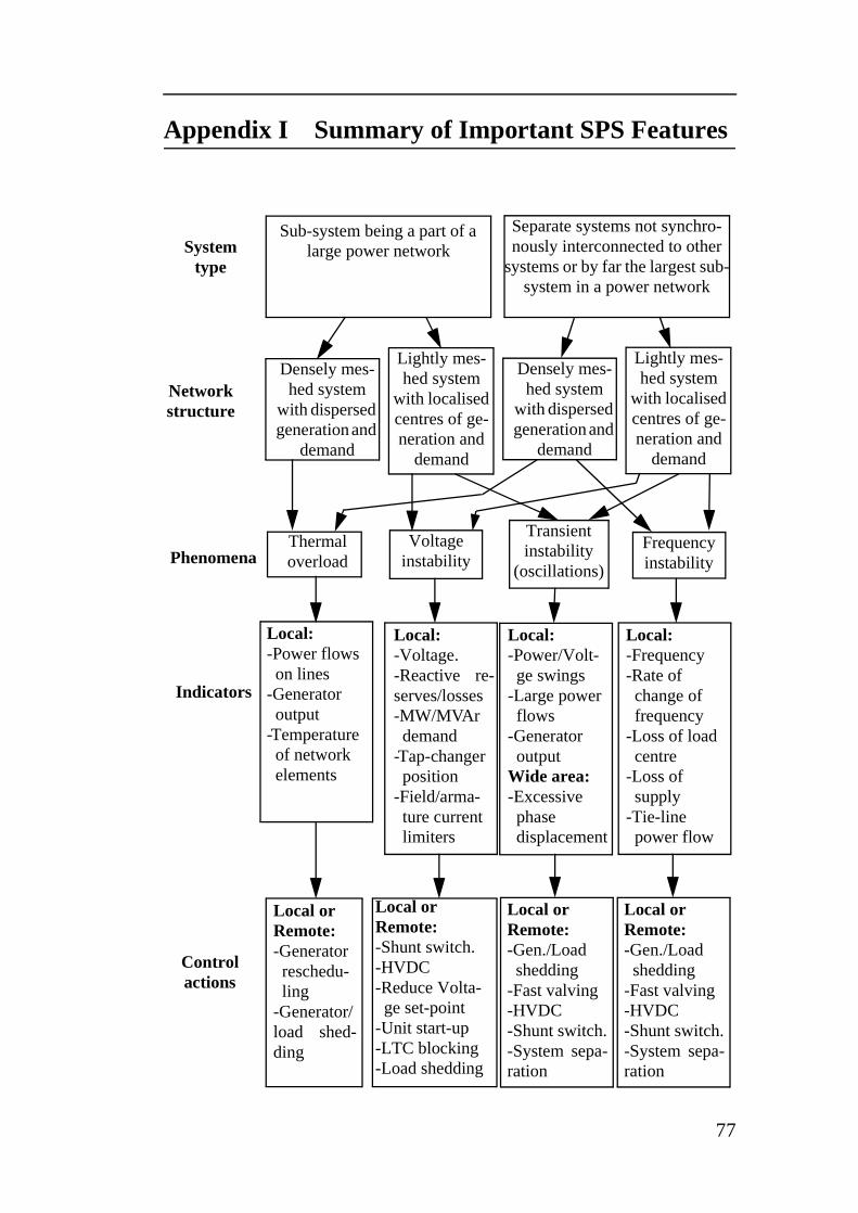
Appendix I Summary of Important SPS Features
Systemtype
Network structure
Phenomena
Indicators
Control actions
Densely mes-hed system
with dispersed generation and
demand
Separate systems not synchro-nously interconnected to other
systems or by far the largest sub-system in a power network
Sub-system being a part of a large power network
Lightly mes-hed system
with localised centres of ge-neration and
demand
Densely mes-hed system
with dispersed generation and
demand
Lightly mes-hed system
with localised centres of ge-neration and
demand
Thermaloverload
Voltage instability
Transient instability
(oscillations)
Frequency instability
Local:-Voltage.-Reactive re-serves/losses-MW/MVArdemand
-Tap-changerposition
-Field/arma-ture currentlimiters
Local:-Power/Volt-ge swings
-Large powerflows
-Generatoroutput
Wide area:-Excessivephase displacement
Local:-Frequency-Rate ofchange offrequency
-Loss of loadcentre
-Loss of supply
-Tie-line power flow
Local orRemote:-Shunt switch.-HVDC-Reduce Volta-ge set-point
-Unit start-up-LTC blocking-Load shedding
Local orRemote:-Generator reschedu-ling
-Generator/load shed-ding
Local:-Power flowson lines
-Generatoroutput
-Temperatureof networkelements
Local orRemote:-Gen./Load shedding
-Fast valving-HVDC-Shunt switch.-System sepa-ration
Local orRemote:-Gen./Load shedding
-Fast valving-HVDC-Shunt switch.-System sepa-ration
77

78
Paper A
An adaptive scheme to prevent undesirable distance protection operation during voltage
instability
M. Jonsson, J. Daalder
Accepted for IEEE Transactions on Power Delivery
Paper B
A new protection scheme to prevent mal-trips due to power swings
M. Jonsson, J. Daalder
Presented at IEEE/PES Transmission and Distribution Conference and Exposition,
October 28 - November 2, 2001, Atlanta, USA.
Paper C
A distance protection scheme to prevent mal-trips during abnormal power system
conditions
M. Jonsson, J. Daalder
Presented at Cigré Study Committee 34 Colloquium and Meeting,
September 10 - 14, 2001, Sibiu, Romania.
Paper D
A new method suitable for real time generator coherency determination
M. Jonsson, M. Begovic, J. Daalder
Submitted to IEEE Transactions on Power Systems
Paper E
A system protection scheme concept to counter inter-area oscillations
M. Jonsson, J. Daalder, M. Begovic
Submitted to IEEE Transactions on Power Delivery
Paper F
An emergency strategy scheme based on conventional distance protection to avoid
complete system collapse
M. Jonsson, J. Daalder, K. Walve
Accepted forIEEE/PES Transmission and Distribution Conference and Exposition,
September 7 - 12, 2003, Dallas, USA.