Embed Size (px)
Citation preview

Protection Strategy Impact on the Interaction Between Converters
by
Syeda Narjis Fatima Zaidi
A thesis submitted in partial fulfillment of the requirements for the degree of
Master of Science
in
Energy Systems
Department of Electrical and Computer Engineering
University of Alberta
© Syeda Narjis Fatima Zaidi, 2020

ii
Abstract
The availability of the renewable energy sources in remote onshore and offshore locations and the
advancements of power electronics have given rise to the use of high voltage direct current
(HVDC) transmission for bulk power transmission. HVDC technology is more economical than
high voltage alternating current (HVAC) technology for power transmission over distances longer
than 500 km. Moreover, HVDC systems can connect unsynchronized AC networks and provide a
controlled transfer of active power.
HVDC systems utilizing voltage source converter (VSC) technology are widely used for
constructing multiterminal DC (MTDC) systems for connection of renewable energy sources to
the grid and are a promising technology for future realization of large HVDC grids. VSCs based
on the modular multilevel converter (MMC) technology provide higher power quality, reliability,
and efficiency as compared to other multilevel converter topologies. Therefore, MMCs are
prominent candidates for various HVDC applications such as MTDC grids, offshore wind farm
systems, and static synchronous compensators (STATCOMs).
In HVDC systems with more than one point-to-point DC link, faults occurring on one DC
link affect all healthy converters, which are in close proximity to the faulted converter. The degree
of the impact of this fault on healthy converters depends on the type of protection strategy used
for DC fault clearance. The literature proposes several protection strategies based on AC circuit
breakers (ACCBs), DC circuit breakers (DCCBs), fault blocking converters, and half-bridge
MMCs (HB-MMCs) augmented with various configurations of thyristors to clear the DC fault. In
this thesis, firstly, the impact of different protection strategies on the point of common coupling

iii
(PCC) and the operation of healthy converters in a test system comprising of HB-MMCs is
evaluated. Secondly, the faulted converter is operated in the STATCOM mode under different
protection strategies, and its impacts on the PCC and the healthy converter are analyzed and
compared. In this study, three protection strategies comprising of ACCBs, DCCBs, and HB-
MMCs augmented with three-phase full-wave thyristor bridges (Graetz bridges) are considered.
Study results show that (i) the protection strategy using DCCBs enables the PCC voltage and
active power of the healthy converter to reach their steady-state values faster than the other two
protection strategies, (ii) the protection strategy using HB-MMCs augmented with Graetz bridges
allows the PCC voltage and active power of the healthy converter to reach their steady-state values
faster than the protection strategy using ACCBs, (iii) the protection strategy using DCCBs has the
shortest fault clearance time than the other two protection strategies, (iv) the protection strategy
using HB-MMCs augmented with Graetz bridges eliminates the fault current faster than the
protection strategy using ACCBs, (v) the STATCOM mode of operation of the faulted converter
restores the PCC voltage to its pre-fault value, whereas without the STATCOM mode, the steady-
state value of the PCC voltage is higher than its pre-fault value, and (vi) the STATCOM mode of
operation of the faulted converter allows active power of the healthy converter to reach its steady-
state value faster than without the STATCOM mode, thereby increasing the reliability and security
of the healthy link.

iv
Acknowledgments
I would like to express my sincere gratitude to my supervisor, Professor Sahar P. Azad, for her
profound knowledge, valuable guidance, patience, and understanding throughout my graduate
studies. Without her consistent help and encouragement, I would not have achieved the goal of
this project.
I am grateful to my co-supervisor, Professor Marek Reformat, for his co-operation and
guidance during my graduate studies.
I would like to express my gratitude to members of the examination committee, Professor
Dr. Hao Liang and Professor Dr. Venkata Dinavahi.
I am thankful to my former colleagues and friends for boosting up my morale.
My heartfelt thanks to my father-in-law, Hasan Zaidi; my mother-in-law, Gulzar Zaidi; and
my husband, Khurram Zaidi for their unconditional help and sacrifice.
I am forever indebted to my parents, Asad Ali and Shahnaz Asad, for giving me the
opportunities and experiences that have made me who I am.

v
Table of Contents
1 Chapter 1 Introduction 1
1.1 Introduction ..................................................................................................................... 1
1.2 Protection of HVDC Systems Under DC Faults ............................................................. 4
1.2.1 Protection with AC Circuit Breakers (ACCBs) ..................................................... 4 1.2.2 Protection with DC Circuit Breakers (DCCBs) ..................................................... 5
1.2.3 Using Fault Blocking Converters .......................................................................... 7 1.2.4 Augmented Fault Blocking Converters Based on HBSMs .................................... 9
1.3 Research Objectives ...................................................................................................... 12
1.4 Methodology.................................................................................................................. 13
1.5 Thesis Outline ................................................................................................................ 14
2 Chapter 2 HVDC System Model 15
2.1 MMC Model .................................................................................................................. 15
2.2 MMC Control System ................................................................................................... 18
2.2.1 Upper-Level Control System ............................................................................... 20 2.2.2 Lower-Level Control system ............................................................................... 21
2.3 Test System ................................................................................................................... 23
2.3.1 Test System Model .............................................................................................. 24
2.3.2 Protection System Model ..................................................................................... 25
2.4 Summary........................................................................................................................ 28
3 Chapter 3 Protection System Impact on Healthy Converters’ Operation 29
3.1 Case Studies................................................................................................................... 30
3.1.1 Case Study 1: HB-MMCs with ACCBs (Protection Strategy I) .......................... 30 3.1.2 Case Study 2: HB-MMCs with DCCBs (Protection Strategy II) ........................ 33 3.1.3 Case Study 3: Augmented HB-MMCs with Graetz Bridges (Protection
Strategy III) ......................................................................................................... 35

vi
3.2 Comparison of the Three Protection Strategies ............................................................. 40
3.3 HB-MMCs Operation as a STATCOM During DC Faults ........................................... 44
3.3.1 Case Study 1: STATCOM Mode I Strategy ........................................................ 44 3.3.2 Case Study 2: STATCOM Mode II Strategy ....................................................... 47 3.3.3 Comparison of STATCOM Mode I and II Strategies .......................................... 49
3.4 Summary........................................................................................................................ 51
4 Chapter 4 Conclusion 52
4.1 Conclusion ..................................................................................................................... 52
4.2 Thesis Contribution ....................................................................................................... 54
4.3 Future Work ................................................................................................................... 54
Bibliography ................................................................................................................................ 56

vii
List of Tables
2.1 Parameters of the test system ................................................................................................ 24
3.1 Comparison of different protection strategies and STATCOM mode strategies .................. 51

viii
List of Figures
1.1 HVDC systems........................................................................................................................ 2
1.2 HB-MMC ................................................................................................................................ 3
1.3 Types of mechanical circuit breakers ..................................................................................... 6
1.4 SSCB ....................................................................................................................................... 6
1.5 Bidirectional HCB .................................................................................................................. 7
1.6 Building blocks of fault blocking converters .......................................................................... 8
1.7 Fault blocking converters ........................................................................................................ 9
1.8 HBSM with anti-parallel thyristors ....................................................................................... 10
1.9 HB-MMC in parallel with the Graetz bridge ........................................................................ 11
2.1 The HBSM ............................................................................................................................ 16
2.2 Thevenin equivalent model of an HB-MMC ........................................................................ 18
2.3 MMC control system ............................................................................................................ 19
2.4 The outer control loop block ................................................................................................. 20
2.5 The inner decoupled current control loop block ................................................................... 21
2.6 Circulating current suppression control block ...................................................................... 23
2.7 The test system ...................................................................................................................... 24
2.8 The model of the AC system ................................................................................................ 25
2.9 DCCB model ......................................................................................................................... 26

ix
2.10 Graetz bridge ....................................................................................................................... 26
2.11 Augmented HB-MMC with a Graetz bridge ...................................................................... 27
3.1 The one-line diagram of the test system ............................................................................... 30
3.2 Fault current under protection strategy I ............................................................................... 31
3.3 Voltage at PCC1 under protection strategy I ......................................................................... 32
3.4 Active power of converter 3 under protection strategy I ...................................................... 32
3.5 Fault current under protection strategy II ............................................................................. 34
3.6 Voltage at PCC1 under protection strategy II ........................................................................ 34
3.7 Active power of converter 3 under protection strategy II ..................................................... 35
3.8 The one-line diagram of the test system under protection strategy III ................................. 36
3.9 Fault current under protection strategy III ............................................................................ 38
3.10 Fault current contribution by converter 1 and Graetz bridge 1 ............................................. 38
3.11 Voltage at PCC1 under protection strategy III ..................................................................... 39
3.12 Active power of converter 3 under protection strategy III .................................................. 39
3.13 Fault current under the three protection strategies ............................................................... 41
3.14 Active power of converter 3 under the three protection strategies ...................................... 41
3.15 Voltage at PCC1 under the three protection strategies ......................................................... 42
3.16 Current through the hybrid switch and the DCCB............................................................... 43
3.17 Voltage across the hybrid switch and the DCCB during fault clearance ............................. 44
3.18 Fault current under protection strategy II and STATCOM mode I strategy ........................ 45

x
3.19 PCC1 voltage under protection strategy II and STATCOM mode I strategy ...................... 46
3.20 Active power of converter 3 under protection strategy II and STATCOM mode I
strategy ................................................................................................................................ 46
3.21 PCC1 voltage under protection strategy III and STATCOM mode II strategy .................... 48
3.22 Active power of converter 3 under protection strategy III and STATCOM mode II
strategy ................................................................................................................................ 48
3.23 Fault current under STATCOM mode II strategy ................................................................ 49
3.24 Graetz bridge’s output current under protection strategy III and STATCOM mode II
strategy ................................................................................................................................ 49
3.25 PCC1 voltage under STATCOM mode I and II strategies ................................................... 50
3.26 Fault current under STATCOM mode I and II strategies .................................................... 50
3.27 Active power of converter 3 under STATCOM modes I and II strategies .......................... 50

xi
List of Acronyms
AAC Alternate Arm Converter
AC Alternating Current
ACCB AC Circuit Breaker
CB Circuit Breaker
CCSC Circulating Current Suppression Control
CDSM Clamp Double Submodule
CVB Capacitor Voltage Balancing
DC Direct Current
DCCB DC Circuit Breaker
EMT Electro-Magnetic Transient
FBSM Full-Bridge SM
HBSM Half-Bridge SM
HCB Hybrid CB
HV High Voltage
HVAC High Voltage AC
HVDC High Voltage DC
IGBT Insulated Gate Bipolar Transistor
LCC Line Commutated Converter
LCS Load Commutation Switch
MCB Mechanical Circuit Breaker
MMC Modular Multilevel Converter
MTDC Multi-Terminal DC
xii
NLC Nearest Level Control
PCC Point of Common Coupling
PI Proportional-Integral
PLL Phase-Locked Loop
PSCAD Power System Computer Aided Design
PD-PWM Phase-Disposition Pulse Width Modulation
PS-PWM Phase-Shift Pulse Width Modulation
RCB Residual Current Breaker
RMS Root-Mean-Square
SF6 Sulphur Hexafluoride
SM Submodule
SSCB Solid-State CB
STATCOM Static Synchronous Compensator
UFD Ultra Fast Disconnector
VSC Voltage Source Converter

1
Chapter 1 Introduction
1.1 Introduction
The generation of electricity from renewables is growing at a fast pace. To cope with the concerns
associated with depleting fossil fuel reserves and global warming, 90% of the electricity in Canada
is expected to be generated from renewable energy sources by 2030 [1]. In 2005, Canada had 600
MW of installed wind power capacity, which increased to 13,000 MW in 2019 [2]. In 2017, 52 GW
of wind power and 95 GW of solar power were installed worldwide, taking the total installed
capacity to 400 MW and 540 GW, respectively [3].
The availability of the renewable energy sources in remote onshore and offshore locations
and the advancements of power electronics have given rise to the use of high voltage direct current
(HVDC) transmission for bulk power transmission [4]-[5]. HVDC technology is more economical
than high voltage alternating current (HVAC) technology for power transmission over distances
longer than 500 km [6]. Moreover, HVDC systems can connect unsynchronized AC networks and
provide a controlled transfer of active power. In contrast, in HVAC systems, the transferred active
power mainly depends on the angle difference between the two ends of the line [5].
The three main topologies for a HVDC system include point-to-point, back-to-back, and
multiterminal connections [5]. In point-to-point HVDC transmission systems, two converter
stations at distant locations are linked together by an overhead DC line, an underground or
submarine DC cable, or a combination of these. In back-to-back HVDC systems, HVDC
transmission line is not needed because the two converter stations are located at the same site. In
multiterminal DC (MTDC) systems, more than two converter stations are connected through a DC
network [6]. There are various advantages associated with MTDC systems as compared to point-
to-point HVDC systems [4]. MTDC topologies provide a cheaper means for power transfer as
compared to several point‐to‐point HVDC links for connecting adjacent AC systems. Faults on a
point‐to‐point HVDC link can lead to the entire system shut down. On the other hand, for a MTDC
network, after the isolation of the faulted link, power can be transferred via power flow re-

2
arrangement. Therefore, a MTDC system provides higher reliability as compared to point-to-point
HVDC systems. Furthermore, due to the presence of multiple renewable energy sources on MTDC
grids, the spinning reserve requirement for AC systems can be reduced. Moreover, in MTDC
systems, power exchange and trading are possible among multiple AC networks, which will help
to reduce the electricity price.
There are two main types of HVDC converters as shown in Fig. 1.1: line commutated
converters (LCCs) and voltage source converters (VSCs) [4]. LCCs use thyristors as switches and
operate as a constant current source. VSCs use insulated gate bipolar transistors (IGBTs) as
switches and operate as a constant DC voltage source [7]. One of the main advantages of VSCs
over LCCs is that VSCs can be connected to weak grids such as offshore wind farms [7]. Moreover,
VSC is the most appropriate technology for constructing multiterminal systems as it benefits from
a constant DC voltage at all the terminals, making parallel connections easy to build and control
[7]. Hence, VSC technology is a promising technology for DC grids [7].
AC source
a) LCC system b) VSC system
DC
output DC
output
AC sourceL
C
Fig. 1.1: HVDC systems
VSCs based on the modular multilevel converter (MMC) technology provide higher power
quality, reliability, efficiency, and cost-weight-volume reduction as compared to other multilevel
converter topologies [8]-[10]. Therefore, MMCs are prominent candidates for various HVDC
applications such as MTDC grids, offshore wind farm systems, and static synchronous
compensators (STATCOMs) [8]-[10]. MMCs consist of a series connection of submodules (SMs)
and are easily adaptable to high voltage levels by increasing the number of SMs [7], [10]. The
larger the number of levels, the better the quality of the produced AC voltage waveform [11]. The
number of SMs required for the design of MMCs depends on the system operating voltage,
application, and rating of IGBT switching devices [12]. In conventional MMCs with half-bridge
(HB) and full-bridge (FB) SMs, all SMs are identical with the same rated power, circuit topology,
and are controlled by the same control and modulation schemes [10]. The HB-MMC has lower
3
conduction losses compared to the FB-MMC, as the latter has a larger number of IGBTs [13]. This
thesis will focus on HB-MMCs.
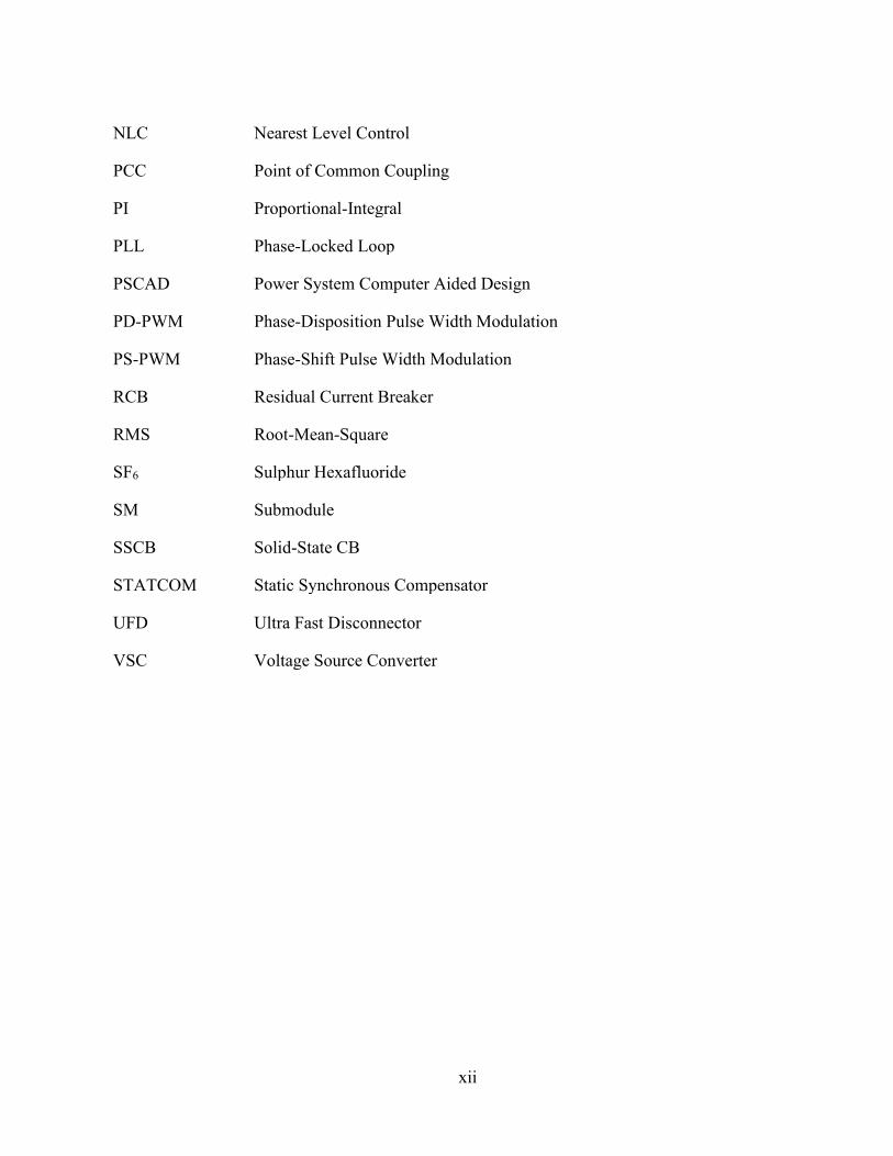
Fig. 1.2 shows a HB-MMC with 𝑛 SMs in each arm [11]. The inductor 𝐿𝑎𝑟𝑚 is added in each
arm to limit arm current harmonics and fault currents. A HB-MMC with 𝑛 SMs per arm has a line-
to-neutral voltage waveform with (𝑛 + 1) levels [14].
HBSM1
HBSM2
HBSMn
HBSM1
HBSM2
HBSMn
HBSM1
HBSM2
HBSMn
HBSM1
HBSM2
HBSMn
HBSM1
HBSM2
HBSMn
HBSM1
HBSM2
HBSMn
Larm Larm Larm
Larm LarmLarm
VDC
HBSM
a) SM topology
T1
T2
C
b) HB-MMC
Lower
arm
Upper
arm
Phase
leg
Fig. 1.2: HB-MMC
Each HBSM can be controlled to output either +𝑉𝐶 (capacitor voltage) or 0 V. By closing
the upper IGBT (𝑇1) and opening the lower IGBT (𝑇2), the capacitor is inserted into the circuit and
the output voltage of the SM is equal to 𝑉𝐶. On the contrary, the output voltage of the SM becomes
zero when the capacitor is bypassed by opening 𝑇1 and closing 𝑇2. The AC voltage is generated in
small steps by inserting or bypassing SMs [11]. Each phase of the three-phase AC system is
connected to the midpoint of each phase leg.

4
1.2 Protection of HVDC Systems Under DC Faults
A HVDC system with MMCs requires fast DC fault clearance, fault isolation, and fault location
identification due to fast transients and high rate of rise of the DC fault current [14]-[17]. Due to
low impedance of the fault current path, the DC fault current increases sharply, even if the MMC
is immediately blocked after the fault, and the DC voltage may collapse quickly [14], [18]. In
HVDC systems where converters are close to each other, the DC fault on one link will influence
the healthy links connected to the same point of common coupling (PCC) [19]. High fault current
flowing from the AC side to the DC fault point will cause a temporary reduction in the voltage at
PCC, which in turn will decrease the power transmitted through the healthy links [19]. Therefore,
it is essential to interrupt the DC fault current quickly to prevent damages to the IGBTs in the
MMCs and to minimize the effect on electrically close healthy converters, such that the system's
reliability and security are maintained. This section discusses the four main protection strategies
used to clear DC faults in HVDC systems.
1.2.1 Protection with AC Circuit Breakers (ACCBs)
To interrupt the DC fault current, the converters are blocked, and the ACCBs are tripped. The
opening time for ACCBs is about 60-100 ms [20]. During this time, converters act as nonlinear
inductive loads and consume a large amount of reactive power. This causes a reduction in voltage
at the PCC [20]. As the ACCBs are located at the AC side of the converters, the tripping of the
ACCBs will interrupt the power flow to healthy links connected to the faulted converter.
This strategy is used in the existing point-to-point VSC-HVDC systems due to the lower cost
of the CBs compared to the other alternative strategies. On the contrary, such a slow protection
system that also lacks selectivity is not a feasible choice for a MTDC system with a large power
transmission capacity [19], [21]. Moreover, the converters cannot operate in STATCOM mode
during the fault current interruption.

5
1.2.2 Protection with DC Circuit Breakers (DCCBs)
During a fault, only DCCBs on the faulted line will be opened. Hence, converters will continue to
transfer power over healthy links [13]. During the fault clearance, converters may stay deblocked
if the arm currents do not exceed the current limit of the IGBTs. Hence, the converters can operate
as a STATCOM during the fault clearance process [13]. However, DCCBs are expensive, and their
reliability is yet to be tested in real-world applications [22].
DCCBs can be classified into three main categories: mechanical CBs (MCBs), solid-
state CBs (SSCBs), and hybrid CBs (HCBs) [14], [23]-[25]. All DCCBs consist of a main
switching element in the nominal path for building the voltage withstand capability, a commutation
path to create the current zero, and an absorber path to dissipate the stored energy [26]. The main
switching element in MCBs and SSCBs is a mechanical breaker and a semiconductor switch,
respectively. A combination of semiconductor switches and mechanical disconnectors are used in
HCB as the main switching element [26].
There are two types of MCBs: passive and active, as shown in Fig. 1.3 [23]. The nominal
current flows through a primary branch (nominal path), which consists of a low loss mechanical
breaker [23]. The mechanical breaker is typically an AC air-blast CB or a sulphur hexafluoride
(SF6) CB for the passive MCB or a vacuum CB for the active MCB [26]. The commutation path
is a series resonance branch consisting of inductors and capacitors. When a fault is detected, the
contacts of the breaker in the primary branch start to open, and an arc is established [26]. The arc
voltage commutates the current to the resonant branch [26]. Then, the current oscillates in the
primary and resonant branches at a natural frequency ꞷ𝑜 =1
√𝐿𝑟𝑒𝑠𝐶𝑟𝑒𝑠. The mechanical breaker
interrupts the arc at a zero-crossing of the current in the primary branch. The current continues to
flow through the resonant branch and charges the capacitor 𝐶𝑟𝑒𝑠 [24]. When the capacitor voltage
exceeds the threshold voltage level of the surge arrester, the current is diverted to the surge arrester
branch, where it reduces to zero [26]. Passive MCBs have longer interruption times, which is in
the order of tens of milliseconds. To reduce the interruption times, active MCBs with pre-charged
capacitor 𝐶𝑟𝑒𝑠 in the resonant branch are used, Fig. 1.3 (b). The fault current interruption time for
active MCBs is 8-10 ms [23]. Although MCBs are cheaper than other types of DCCBs, they have
a longer interruption time.

6
Surge Arrester
CB1
Primary branch
CresLresS1
Resonant branch
S2
Surge Arrester
CB1
Primary branch
CresLresS1
Resonant branch
a) Passive resonant MCB b) Active resonant MCB
Fig. 1.3: Types of mechanical circuit breakers
SSCBs consist of high-power semiconductor switches such as IGBTs and have no moving
parts, as shown in Fig. 1.4 [23]. Therefore, they operate in a few microseconds. However, the on-
state resistance of the IGBTs results in heating and power losses during their operation [27]. Surge
arresters are connected in parallel to the IGBTs to absorb the fault energy.
Surge Arrester Surge Arrester Surge Arrester
Fig. 1.4: SSCB
HCBs offer the benefits of MCBs and SSCBs including low conduction losses and fast fault
current interruption. Low conduction losses during normal operation are achieved by using a series
combination of few IGBTs, known as the load commutation switch (LCS), and an ultrafast
mechanical disconnector (UFD), as shown in Fig. 1.5. The commutation path or the main breaker
branch is mainly composed of fully-controlled semiconductor switches such as IGBTs. The
presence of semiconductor switches ensures fast current breaking in the order of 2-3 ms to isolate
the DC fault [13]. The HCB operation starts with turning off the LCS to commutate the current
into the main breaker branch. When the current through LCS reaches zero, UFD will start to open
to protect the LCS from high voltages. A fast UFD can open in 2 ms [28]. The IGBTs in the main
breaker branch will remain on until the UFD is fully opened. After the IGBTs in the main breaker
branch are turned off, the current is transferred into the surge arrester branch, where the surge
7
arresters absorb the fault energy. Once the current through the faulted link falls below the residual
current limit, residual current breaker (RCB) opens and fully isolates the faulted link [29].
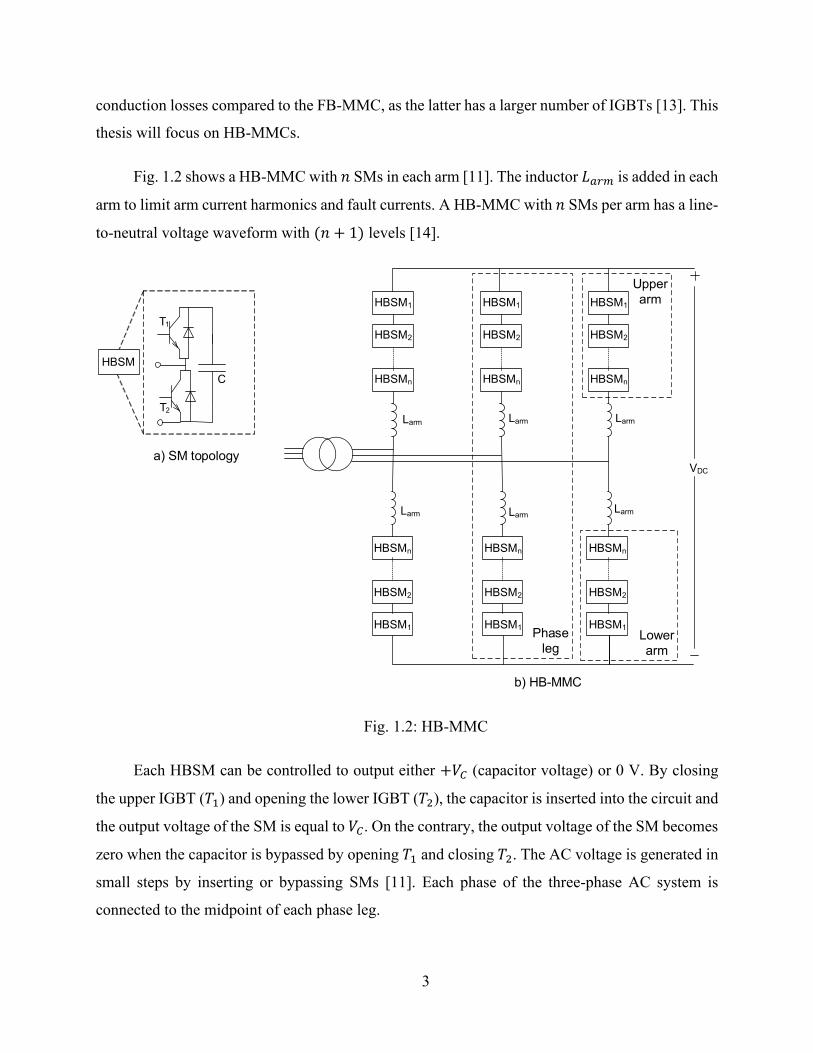
HCBs can provide unidirectional or bidirectional fault current breaking capability [29]. A
unidirectional HCB conducts the normal current in both directions, but it can interrupt the fault
current in only one direction. A unidirectional HCB is less complex and less expensive as
compared to a bidirectional HCB [29]. However, the bidirectional breaking capability of DCCBs
is required to provide back-up protection and bus-bar protection [29]. This thesis will focus on
bidirectional HCBs (Fig 1.5), which will be referred to as DCCBs in the remainder of this thesis.
Surge Arrester Surge Arrester
Main Breaker
LCS
UFDRCB
Fig. 1.5: Bidirectional HCB
1.2.3 Using Fault Blocking Converters
HBSMs do not provide DC fault blocking capability. When a fault occurs on the DC side, and
IGBTs of the converter are blocked, the fault current continues to flow from the AC side to the
fault point on the DC side through anti-parallel diodes of the converter [30]. Alternate SMs capable
of blocking the AC system from feeding the fault can be used in HVDC systems to interrupt the
DC fault current [30].
Some of the MMC topologies with DC fault-blocking capability are based on FBSMs, a
combination of HBSMs and FBSMs, alternative-arm converter (AAC), and clamp double SMs
(CDSM), shown in Figs. 1.6 and 1.7 [31]. In these topologies, a negative voltage is imposed across
the antiparallel diodes of the converter. The diodes will be reverse-biased due to the negative
voltage and consequently, the fault current will be interrupted [31]. Moreover, these topologies
can operate in the STATCOM mode to support the AC grid during DC faults [31]. However, such

8
topologies suffer from large conduction losses and are more expensive as compared to HB-MMCs
[12], [31]-[33]. The most common types of MMCs with fault blocking capability are:
• FB-MMCs: FBSMs are controlled to output either +𝑉𝐶, −𝑉𝐶, or 0 V. FBSMs have twice
as many IGBTs as HBSMs; therefore, the power losses in FBSMs are higher than HBSMs.
During a DC fault, all IGBTs of the FBSM are blocked. Then the capacitors insert a reverse
voltage in the fault current path to prevent the AC side contribution to the DC fault current,
and to reduce the fault current to zero [34].
• MMCs with CDSMs: The CDSM consists of two HBSMs connected in series through
two diodes and one IGBT with its anti-parallel diode [30]. In the case of a DC fault, all the
IGBTs are blocked, and the two capacitors in the CDSM will be in parallel providing an
opposing voltage in the fault current path [30]. Therefore, the fault current will be forced
to zero. With the same number of voltage levels, the power losses of CDSMs are higher
than HBSMs and lower than FBSMs [30].
• Hybrid MMCs: The hybrid MMC utilizes a combination of HBSMs and FBSMs
connected in series in each arm [35]. The ratio of the number of FBSMs to HBSMs is
selected such that the capacitor voltage balance is maintained and the dc fault blocking
capability is achieved [35]. Upon the occurrence of a DC fault, IGBTs in the hybrid MMC
are blocked, and the hybrid MMC operates like a FBSM, and thus the fault current is
reduced to zero [35].
• AACs: The AAC consists of a series combination of FBSMs and IGBTs (called the
director switches) in each arm to achieve DC fault blocking capability. Due to the
implementation of FBSMs, a negative voltage is generated by the arm during the fault, and
therefore, the AC system contribution to the DC fault can be blocked [30].
FBSMHBSM Director
switchCDSM
Fig. 1.6: Building blocks of fault blocking converters

9
FBSM
FBSM
HBSM
HBSM
FBSM
FBSM
HBSM
HBSM
FBSM
FBSM
HBSM
HBSM
FBSM
FBSM
HBSM
HBSM
FBSM
FBSM
HBSM
HBSM
FBSM
FBSM
HBSM
HBSM
c) Hybrid MMC
CDSM
CDSM
CDSM
CDSM
CDSM
CDSM
CDSM
CDSM
CDSM
CDSM
CDSM
CDSM
CDSM
CDSM
CDSM
CDSM
CDSM
CDSM
CDSM
CDSM
CDSM
CDSM
CDSM
CDSM
e) AACd) CDSM-MMC
FBSM
FBSM
FBSM
FBSM
FBSM
FBSM
FBSM
FBSM
FBSM
FBSM
FBSM
FBSM
FBSM
FBSM
FBSM
FBSM
FBSM
FBSM
FBSM
FBSM
FBSM
FBSM
FBSM
FBSM
b) FBSM-MMC
FBSM
FBSM
FBSM
FBSM
Director
switch
FBSM
FBSM
FBSM
FBSM
Director
switch
FBSM
FBSM
FBSM
FBSM
Director
switch
FBSM
FBSM
FBSM
FBSM
Director
switch
FBSM
FBSM
FBSM
FBSM
Director
switch
FBSM
FBSM
FBSM
FBSM
Director
switch
Fig. 1.7: Fault blocking converters
The fault blocking converters are capable of producing bipolar voltages as opposed to
HBSMs, which can only produce a positive or zero voltage. Furthermore, for the operation of the
converters during DC faults as a STATCOM, the converter SMs should be able to generate bipolar
voltages so that the converter can remain deblocked [31]. Therefore, unlike HBSMs, the fault
blocking converters can be operated in the STATCOM mode during faults [31]. The fault blocking
converters can be operated in the STATCOM mode by controlling the upper and lower arm SMs
such that they conduct alternatively [31], [36]. When the phase current is positive, all of the SMs
in the lower arm are blocked [36]. Due to the reverse voltage of SM capacitors in the blocked arm,
the fault current decays rapidly [36]. Therefore, the AC current only flows through the upper arm.
When the phase current is negative, the upper arm is blocked, while the lower arm conducts [36].
Hence, the phase current in the conducting arms can be regulated to supply reactive power to the
AC grid during the fault [36].
1.2.4 Augmented Fault Blocking Converters Based on HBSMs
In addition to the fault blocking converters described in the previous section, other converter
topologies that combine HBSMs and thyristors are proposed to enable HB-MMCs to interrupt the

10
DC fault current without using ACCBs or DCCBs. While the fault blocking converters interrupt
the fault current by applying a negative voltage across the antiparallel diodes, the augmented HB-
MMC topologies eliminate the AC infeed by providing a low impedance path, comprising of
thyristors, in parallel to the antiparallel diodes of the HBSMs. The augmented HB-MMC
topologies are cost-effective as compared to fault blocking converters and DCCBs [37]-[38]. The
augmented topologies have lower conduction losses as compared to fault blocking converters [39].
Moreover, the augmented HB-MMCs can handle higher fault currents as thyristors have a higher
surge current capacity than IGBTs or diodes [39].
In [37], a pair of antiparallel thyristors is connected across the lower diode in each HBSM
and turned on only during the fault, Fig. 1.8. The two thyristors are controlled by the same gate
signal. After the detection of a fault, the HB-MMC is blocked, and the thyristors are turned on
simultaneously. The thyristor has a lower on-state impedance than the diode; therefore, the
majority of the fault current is conducted by the thyristor [39]-[40]. Consequently, six arms of the
HB-MMC become six R-L branches after triggering the thyristors and the DC fault current 𝑖𝐷𝐶(𝑡)
can be calculated by (1.1)
𝑖𝐷𝐶(𝑡) = 𝐼0𝑒−
𝑡−𝑡0𝜏 ,
(1.1)
where 𝑡0 is the instant of triggering the thyristors, 𝐼0 = 𝑖𝐷𝐶(𝑡0) and, 𝜏 =𝐿𝑒𝑞
𝑅𝑒𝑞 is the time constant
which depends upon the equivalent resistance 𝑅𝑒𝑞 and inductance 𝐿𝑒𝑞 of the fault current path.
The equation for 𝑖𝐷𝐶(𝑡) shows that the fault current will decay to zero.
Fig. 1.8: HBSM with anti-parallel thyristors
In [41], all pairs of antiparallel thyristors are combined and connected across the AC side of
the HB-MMC instead of being connected across each HBSM as done in [37]. As a result, this

11
topology is easier to implement than the topology of [37]. The topologies proposed in [37] and
[41] do not allow the operation of the HB-MMC in the STATCOM mode because the HB-MMC
is blocked during the entire fault clearance process.
In [28] and [38], a three-phase full-wave thyristor bridge, called Graetz bridge, is connected
in parallel to a HB-MMC converter shown in Fig. 1.9. In this topology, the DC output terminals
of the Graetz bridge are connected to the DC terminals of the HB-MMC through a hybrid switch.
The AC side of the Graetz bridge rectifier is connected to the AC side of the MMC [28]. A series
combination of LCS and UFD forms the hybrid switch. A surge arrester is connected in parallel to
the LCS to dissipate the energy stored in the arm inductors when the hybrid switch is opened.
HBSM1
HBSM2
HBSMn
HBSM1
HBSM2
HBSMn
HBSM1
HBSM2
HBSMn
HBSM1
HBSM2
HBSMn
HBSM1
HBSM2
HBSMn
HBSM1
HBSM2
HBSMn
Larm Larm Larm
Larm LarmLarm
Hybrid
switchx1
y1 y2
x2
VDC
Hybrid
switch
Fig. 1.9: HB-MMC in parallel with the Graetz bridge
The Graetz bridge is triggered only during the fault. Once the fault is detected, the HB-MMC
is blocked, and the Graetz bridge is fired as a rectifier at a minimum firing angle. For a rectifier,
the minimum firing angle is 2-5 degrees to ensure proper firing of the thyristors [42]. A positive
DC voltage is generated at the output of the Graetz bridge, and the Graetz bridge begins to share
the fault current with the HB-MMC. Then, a trip signal is sent to the LCS and UFD and the DC

12
side of the HB-MMC is disconnected from the DC side of the Graetz bridge. When the HB-MMC
is fully isolated from the fault, it can be operated as a STATCOM to compensate for the voltage
dip at the PCC. Once the hybrid switch is opened, the Graetz bridge is fired at an angle greater
than 90 degrees to operate as an inverter [42]. The output voltage of the Graetz bridge becomes
negative, and the fault energy is exported from the DC side into the AC side. Consequently, the
fault current is reduced to zero. This fault clearing process is similar to the force retard operation
of LCCs [28]. The Graetz bridge is blocked after the fault clearance.
1.3 Research Objectives
The protection strategies described in the previous section affect the healthy converters in
proximity of the faulted converter in different ways. The extent of the impact of the faulted
converters on the healthy converters mainly depends on the speed of the protection system and
whether the protection strategy enables the faulted converters to be controlled to provide reactive
power compensation during the fault clearance. The operation of a faulted converter as a
STATCOM during the fault clearance provides voltage support to the PCC during DC faults and
reduces the impact of the faulted converter on the operation of the healthy converters.
Protection strategies based on ACCBs have the highest fault clearance time and do not allow
the STATCOM operation of the faulted converter because the converter cannot be deblocked until
the fault is cleared. The fast fault clearance time of protection strategies based on DCCBs may
prevent the arm currents from reaching the IGBTs' current limits. Consequently, the converter may
remain deblocked and operate as a STATCOM during the DC fault. The fault blocking converters
apply a negative voltage across the antiparallel diodes and thereby reduce the fault current to zero
without using ACCBs or DCCBs. The fault blocking converters can be operated as STATCOMs
during the DC faults as they can remain deblocked. The augmented HB-MMCs with thyristors
eliminate the freewheeling effect of the antiparallel diodes (after all IGBTs are blocked) by
diverting the fault current to a low impedance path formed by the thyristors. The thyristor branch
either transforms the six MMC arms into a source-free resistive-inductive circuit and the fault
current freely decays to zero, or it forms a Graetz bridge and uses force retard principle to reduce
the fault current to zero. The augmented HB-MMC with the Graetz bridge allows the faulted
converter to operate in the STATCOM mode during fault clearance.

13
The impact of DC faults on electrically close converters with protection strategies based on
ACCBs and DCCBs has been studied in [16]. The impact of protection strategies involving fault
blocking converters on the PCC voltage is studied in [15], [39], [43]. However, [15], [39], [43]
do not examine the impact of faulted converters on healthy converters. The impact of DC faults
on the PCC voltage and electrically close converters with protection strategies based on
augmented HB-MMCs has not been studied in the literature. Moreover, the impact of the operation
of the faulted converter as a STATCOM to minimize the interaction between healthy and faulty
converters has not been studied in the literature.
The objectives of this thesis are to (i) analyze the impact of the three protection strategies
based on ACCBs, DCCBs, and augmented HB-MMCs with Graetz bridges on the PCC voltage
and the operation of electrically close healthy converter to a faulted converter, and (ii) investigate
the possibility of the STATCOM operation of faulted converter to minimize the DC fault impact
on electrically close healthy converter.
1.4 Methodology
To achieve the thesis objectives, the following methodology is used:
• Constructing a test system in PSCAD/EMTDC, in which two point-to-point VSC-HVDC
systems are connected to the same AC system on the rectifier side. The test system has
only HB-MMCs.
• Analyzing and comparing the voltage at PCC and the active power of healthy converter
close to the faulted converter when protection strategies based on ACCBs, DCCBs and
augmented HB-MMCs with Graetz bridges are used.
• Analyzing and comparing the DC fault current when protection strategies based on
ACCBs, DCCBs and HB-MMCs augmented with Graetz bridges are used.
• Analyzing and comparing the voltage at PCC and the active power of healthy converter
when the faulted converter is operated as a STATCOM under protection strategies based
on DCCBs and HB-MMCs augmented with Graetz bridges.

14
1.5 Thesis Outline
The rest of this thesis is organized as follows:
• Chapter 2 provides an overview of the modelling techniques and control of the HB-
MMCs. A brief description of the test system and the modelling of various components
such as ACCBs, DCCBs and augmented HB-MMCs with Graetz bridges is also provided.
• Chapter 3 investigates the impact of different protection strategies on the PCC voltage and
the operation of healthy converter close to the faulted converter. The study is repeated for
the case when the faulted converter is operated as a STATCOM.
• Chapter 4 summarizes this thesis, presents conclusions and contributions of this research,
and recommends future work directions.

15
Chapter 2 HVDC System Model
This chapter provides a brief description of the model and control system of conventional HB-
MMCs, and the augmented HB-MMCs with Graetz bridges. The description of the test system and
the models of ACCBs, DCCBs, and transmission lines are also provided.
2.1 MMC Model
MMCs are represented in electromagnetic transient (EMT) simulation software environments
with different types of models based on the type of analysis and studies that they are required for
[44]. The following are the three main types of models for representing MMCs in EMT simulation
tools [45], [46]:
1. Full detailed model: In this model, the nonlinear behaviour of IGBTs/diodes is modelled
by nonlinear resistors. This model is suitable for studying SM faults [45].
2. Average value model: In this model, the AC side and DC side characteristics of the MMCs
are modelled as controlled voltage and current sources, respectively. This model is suitable
for the study of harmonics and AC and DC transients [45].
3. Thevenin equivalent model: In this model, series-connected SMs of MMCs are replaced
by a Thevenin equivalent circuit. This model is suitable for the analysis of AC and DC
faults outside the SMs [45].
The HB-MMC studied in the thesis is represented by using the Thevenin equivalent model.
The output voltage 𝑉𝑆𝑀 of each SM in Fig. 2.1 is equal to the capacitor voltage 𝑉𝐶 when the IGBT
𝑇1 is on (SM is inserted). When the SM is inserted, it allows the capacitor to charge or discharge.
𝑉𝑆𝑀 is zero when the IGBT 𝑇2 is on (SM is bypassed) and the capacitor voltage remains constant
[45]. When both IGBTs 𝑇1 and 𝑇2 are off (SM is blocked), the capacitor may charge through the
diode of 𝑇1, but it cannot discharge [45] and 𝑉𝑆𝑀 depends upon the direction of the SM current 𝐼𝑆𝑀
[47]. This mode is used for the energization of the converter and during faults to protect the IGBTs
from overcurrent conditions [48].

16
T1
T2
Ic
VSM
Vc
ISM
Fig. 2.1: The HBSM
The Thevenin equivalent model of a HBSM is shown in Fig. 2.2. Resistances 𝑅1 and
𝑅2 represent the conduction losses of the upper and lower IGBTs of each SM, respectively
[45],[49]. The values of 𝑅1 and 𝑅2 depend upon the gating signals and direction of 𝐼𝑆𝑀 [45]. If a
SM is inserted, then 𝑅1 = 𝑅𝑜𝑛 and 𝑅2 = 𝑅𝑜𝑓𝑓 [47]. If a SM is bypassed, then 𝑅1 = 𝑅𝑜𝑓𝑓 and 𝑅2 =
𝑅𝑜𝑛 [47]. If a SM is blocked provided that 𝐼𝑆𝑀 > 0 and 𝑉𝑆𝑀(𝑡 − ∆𝑇) > 𝑉𝑐(𝑡 − ∆𝑇), then 𝑅1 =
𝑅𝑜𝑛 and 𝑅2 = 𝑅𝑜𝑓𝑓 [47]. On the other hand, if a SM is blocked provided that 𝐼𝑆𝑀 < 0 and
𝑉𝑆𝑀(𝑡 − ∆𝑇) < 0, then 𝑅1 = 𝑅𝑜𝑓𝑓 and 𝑅2 = 𝑅𝑜𝑛 [47]. Otherwise, if a SM is blocked and none of
the aforementioned conditions for 𝑉𝑆𝑀(𝑡 − ∆𝑇) are satisfed, then 𝑅1 = 𝑅𝑜𝑓𝑓 and 𝑅2 = 𝑅𝑜𝑓𝑓 [47].
∆𝑇 is the integration time step, 𝑅𝑜𝑛 and 𝑅𝑜𝑓𝑓 are the on-state and off-state IGBT resistances,
respectively.
The voltage 𝑉𝑐(𝑡) across each SM capacitor, having capacitance 𝐶, is given by
𝑉𝑐(𝑡) =1
𝐶∫ 𝐼𝑐(𝑡) 𝑑𝑡
𝑡
0
, (2.1)
(2.1) can be solved by using the trapezoidal integration method, in which each SM capacitor
voltage is replaced by an equivalent voltage history source 𝑉𝑐𝑒𝑞 in series with a resistor 𝑅𝑐 =
∆𝑇2𝐶⁄ as given by (2.2) [45], [49].
where,
𝑉𝑐(𝑡) = 𝑅𝑐. 𝐼𝑐(𝑡) + 𝑉𝑐𝑒𝑞(𝑡 − ∆𝑇), (2.2)

17
Each HBSM can be represented by a Thevenin equivalent circuit comprising of a Thevenin
voltage source 𝑉𝑆𝑀𝑒𝑞(𝑡 − ∆𝑇) and a Thevenin equivalent resistance 𝑅𝑆𝑀𝑒𝑞 given by (2.4) and (2.5),
respectively.
Now, the output voltage 𝑉𝑆𝑀 of each HBSM is given by (2.6)
As the 𝑛 SMs are connected in series in each arm, the arm can also be represented by a
Thevenin equivalent circuit, as shown in Fig. 2.2, composed of the Thevenin voltage source 𝑉𝑒𝑞(𝑡)
and Thevenin resistance 𝑅𝑒𝑞 given by
𝑉𝑎𝑟𝑚(𝑡) = 𝑅𝑒𝑞. 𝐼𝑎𝑟𝑚(𝑡) + 𝑉𝑒𝑞, (2.7)
𝑅𝑒𝑞 = ∑ 𝑅𝑆𝑀𝑒𝑞𝑖
𝑛𝑖=1 , (2.8)
where,
𝑉𝑐𝑒𝑞(𝑡 − ∆𝑇) =∆𝑇
2𝐶 𝐼𝑐 (𝑡 − ∆𝑇) + 𝑉𝑐(𝑡 − ∆𝑇), (2.3)
𝑅𝑆𝑀𝑒𝑞 = 𝑅2 (1 −𝑅2
(𝑅1+𝑅2+𝑅𝑐)),
(2.4)
𝑉𝑆𝑀𝑒𝑞(𝑡 − ∆𝑇) =𝑅2
(𝑅1+𝑅2+𝑅𝑐) × 𝑉𝑐𝑒𝑞(𝑡 − ∆𝑇), (2.5)
𝑉𝑆𝑀(𝑡) = 𝑅𝑆𝑀𝑒𝑞 . 𝐼𝑆𝑀(𝑡) + 𝑉𝑆𝑀𝑒𝑞(𝑡 − ∆𝑇), (2.6)
𝑉𝑒𝑞 = ∑ 𝑉𝑆𝑀𝑒𝑞𝑖(𝑡 − ∆𝑇)𝑛
𝑖=1 , (2.9)
𝐼𝑎𝑟𝑚(𝑡) = 𝐼𝑆𝑀(𝑡). (2.10)

18
Vceq
R2
Vc
VSM
ISM
Ic
R1
Rc
R1
VceqR2
Iarm Rc
VceqR2
Rc
VceqR2
Rc
R1
R1
x
y
Veq
Varm
Iarm
Req
x
y
T1
T2
Ic
VSM
Vc
ISM
Upper Arm of the MMC
Fig. 2.2: Thevenin equivalent model of an HB-MMC
2.2 MMC Control System
The vector control is widely used in the control of MMC-based HVDC systems [18]. In vector
control, Park’s transformation is used to transform the three-phase system variables in the
stationary-abc frame to system variables in the dq reference frame, which is rotating at system
frequency. Using Park’s transformation, the time-varying signals become DC variables in the dq-
frame and can be controlled by using a proportional-integral (PI) regulator without any steady-
state error [18]. In the dq-frame, the d (direct) and q (quadrature) axes are perpendicular to each
other. The grid voltage 𝑉𝑎𝑏𝑐 is measured and its angle 𝜃 is used to transform the three-phase
voltages and currents from the abc-frame to the dq-frame. A phase-locked loop (PLL) is designed
such that the q-axis component of 𝑉𝑎𝑏𝑐 (𝑉𝑞) is regulated at zero in the steady-state and the d-axis
component of 𝑉𝑎𝑏𝑐 (𝑉𝑑) is equal to the peak value of the phase voltage [50]. Setting 𝑉𝑞= 0 in (2.11)
and (2.12) shows that the active power 𝑃 and reactive power Q on the AC side of the converter can
be controlled independently by controlling 𝐼𝑑 and 𝐼𝑞, respectively.

19
𝑃 = 1.5(𝑉𝑑𝐼𝑑 + 𝑉𝑞𝐼𝑞), (2.11)
𝑄 = 1.5(𝑉𝑞𝐼𝑑 − 𝑉𝑑𝐼𝑞). (2.12)
The control system of the MMC consists of the upper-level and lower-level control systems,
as shown in Fig. 2.3.
PLL
Outer Control
VDC or P
VAC or Q
Id,ref
Iq,ref
Inner Decoupled
Current Control
Vd,ref
Vq,ref
dq/abc
Vabc,ref
Upper Level
Controls
abc/dqIabc
Vabc
Id Iq
Vd Vq,
,
θ
Lower Level
ControlsModulation, Capacitor Voltage Balancing,
Circulating Current Suppression
Switching
Signals
VDC
VabcP,Q,Iabc
IDC
Fig. 2.3: MMC control system

20
2.2.1 Upper-Level Control System
The upper-level controls are divided into two control blocks: outer control block and inner
decoupled current control block. The outer control block consists of two control loops for
controlling the active power ( or DC voltage) and reactive power (or AC voltage) as shown in Fig.
2.4. These control loops generate the reference signals 𝐼𝑑,𝑟𝑒𝑓 and 𝐼𝑞,𝑟𝑒𝑓 for the inner current control
loops [7].
PI
VDC
VDC, ref
PI
P
Pref
PI
Q
Q ref
PIVAC, ref
VAC
Id
Iq
Current
limiter Id,ref
Iq,ref
Fig. 2.4: The outer control loop block

21
The measured grid currents are transformed into dq components, 𝐼𝑑 and 𝐼𝑞 , respectively. 𝐼𝑑 and 𝐼𝑞
are regulated against current references, 𝐼𝑑,𝑟𝑒𝑓 and 𝐼𝑞,𝑟𝑒𝑓, respectively, via PI controllers in the
inner decoupled current control blocks, as shown in Fig. 2.5. The PI controllers’ output is added
to the grid voltage components 𝑉𝑑 and 𝑉𝑞 and the cross-decoupling voltage terms 𝜔𝐿𝐼𝑑 and 𝜔𝐿𝐼𝑞,
where 𝐿 is the sum of converter and transformer leakage inductances. Finally, the inner decoupled
current controller generates the reference d- and q-axes components of the AC voltage (𝑉𝑑,𝑟𝑒𝑓 and
𝑉𝑞,𝑟𝑒𝑓). These voltages are transformed into the abc-frame as 𝑉𝑎𝑏𝑐,𝑟𝑒𝑓, and then sent to the lower-
level control system as reference AC voltage waveforms.
PI
PI
Id
Iq
Id,ref
Iq,ref
ωL
ωL
Vd
Vq
Vd,ref
Vq,ref
θ
Vabc, ref
d-q
abc
Fig. 2.5: The inner decoupled current control loop block
2.2.2 Lower-Level Control system
Unlike the upper-level control system, the lower-level control system is specific to the converter
topology [45]. The lower-level control system is responsible for generating the gating pulses
necessary to produce the reference AC voltage waveform, which is the output of the upper-level
control system. The lower-level control system used for the HB-MMC of this thesis has three
functions: (i) modulation, (ii) capacitor voltage balancing (CVB), and (iii) circulating current
suppression control (CCSC).

22
The objective of the modulation is to determine the number of inserted SMs in both the upper
and lower arms of the HB-MMC, 𝑛𝑢𝑝𝑝𝑒𝑟 and 𝑛𝑙𝑜𝑤𝑒𝑟, respectively. There are always 𝑛 SMs
switched on at any time in one phase leg of the HB-MMC, where 𝑛 = (𝑛𝑢𝑝𝑝𝑒𝑟 + 𝑛𝑙𝑜𝑤𝑒𝑟) and 𝑛 is
the number of SMs per arm. In this thesis, 𝑛 = 76. The common modulation schemes for HB-
MMCs are phase-disposition pulse width modulation (PD-PWM), phase-shift pulse width
modulation (PS-PWM), and nearest level control (NLC) [45]. In this thesis, PS-PWM is used for
the HB-MMC. In PS-PWM, there are 𝑛 triangular carrier signals, for each arm, with a frequency
equal to the switching frequency of the SM, and adjacent triangular carrier waveforms are shifted
in phase with a step of (360𝑜
𝑛) [51]. These triangular carrier signals are then compared with the
reference AC voltage to determine the number of SMs to be inserted [51]. When the reference
value is higher than the value of the carrier signal, the corresponding switching signal becomes
“1,” and the SM is inserted. The switching signal becomes “0” when the reference value is lower
than the value of the carrier signal, and the SM is bypassed [51].
The required number of inserted SMs, determined by the PS-PWM modulation block, is sent
to another control block for CVB. This block aims to balance the capacitor voltages of all the SMs
and keep them equal during normal operation to ensure the stable operation of the HB-MMC under
various operating conditions. The inputs to the CVB control block include 𝑛𝑢𝑝𝑝𝑒𝑟 and 𝑛𝑙𝑜𝑤𝑒𝑟, the
direction of arm current, and the SM capacitor voltages, which are sorted in the descending order
[52]. If the upper (lower) arm current is positive, then out of 𝑛 SMs of the corresponding
arm, 𝑛𝑢𝑝𝑝𝑒𝑟 (𝑛𝑙𝑜𝑤𝑒𝑟) of the SMs with the lowest voltages are inserted to balance the capacitor
voltages. Consequently, the corresponding SM capacitors are charged, and their voltages increase.
If the upper (lower) arm current is negative, then out of 𝑛 SMs of the corresponding arm, 𝑛𝑢𝑝𝑝𝑒𝑟
(𝑛𝑙𝑜𝑤𝑒𝑟) of the SMs with the highest voltages are inserted. Consequently, the corresponding SM
capacitors are discharged, and their voltages decrease [52].
The switching mismatches between the upper and lower arm SMs and the ripple in SM
capacitors voltage create a voltage difference between the upper and lower arms of the phase legs
[18], [23]. This voltage difference creates circulating currents which circulate within the three
phase legs of the HB-MMC. They do not affect the AC or DC sides of the MMC but distort the
arm currents, increase power losses of the MMC and increase the ratings of IGBTs of the SMs.

23
The circulating current consists of a negative sequence component at twice the system's
fundamental frequency.
In this thesis, a controller in the dq-frame rotating at twice the system frequency (2𝜔0𝑡) is
employed to suppress the circulating current, as shown in Fig. 2.6 [45]. The measured current of
upper and lower arms of each phase leg 𝑗, 𝐼𝑢𝑝_𝑗 and 𝐼𝑙𝑜𝑤_𝑗 , are added together. The resultant current
signal 𝐼𝑧_𝑗 is the sum of the circulating current of the two arms and one-third of the converter DC
current. 𝐼𝑧_𝑗 is transformed into the dq-frame. The reference dq currents 𝐼𝑧𝑑∗ and 𝐼𝑧𝑞
∗ are set to zero,
and the PI controllers are used to eliminate the error between the reference and measured currents.
Hence, the circulating current is suppressed. The d- and q-axes current control loops are decoupled
by adding the induced speed voltage terms to the current control loops. This generates the reference
voltage commands 𝑈𝑧𝑑 and 𝑈𝑧𝑞, which are transformed back to the abc-frame. The voltage 𝑈𝑧_𝑗 in
the abc-frame is added to the reference AC voltage before modulation.
Fig. 2.6: Circulating current suppression control block
2.3 Test System
The test system comprises of two point-to-point HVDC transmission systems sharing a common
AC system at one end, as shown in Fig. 2.7. The two transmission systems have symmetric
monopole configurations. The length of each overhead DC transmission line is 400 km. All four
converters are HB-MMCs. Converters 1 and 3 operate as rectifiers and regulate the active power
flow through the transmission systems. Converters 2 and 4 work as inverters and control the DC
bus voltage. All the converters operate in reactive power control mode. Each converter station has

24
an isolation transformer with solidly grounded Y connected winding on the AC grid side and ∆
connected winding on the converter side. The transformer also works as a smoothing reactor and
limits the short-circuit current into the IGBTs of the converters [7]. A passive AC filter is also
present on the AC side of the converters to reduce the higher-order voltage and current harmonics
[7], [53]. Table 2.1 shows the system parameters.
AC system
1
AC system
3
AC system
2
Line 1-2
Line 3-4
Converter
3
Converter
4
Converter
2Converter
1PCC1
LDC
LDCLDC
LDC
Fig. 2.7: The test system
Table 2.1: Parameters of the test system
Specifications
DC side voltage 500 kV
DC side power 600 MW
Converter rated power 1000 MW
AC grid voltage 230 kV
Transformer ratio 230:370
2.3.1 Test System Model
The AC system is represented by a Thevenin equivalent circuit as shown in Fig. 2.8. The Thevenin
source voltage is adjusted to provide the required AC voltage on the converter side, and the
Thevenin impedance is selected to provide the desired short circuit ratio (SCR) [53]. SCR= 2.5 for
each of the three AC sources in the test system.

25
LR1
R2
Fig. 2.8: The model of the AC system
The transmission line is represented with a frequency-dependent travelling wave model. This
modelling technique accurately represents the frequency dependency of the line parameters and
this is the appropriate model for the study of faults. Hence, a precise simulation of faults is
achieved [45]. The point-to-point HVDC systems have a symmetric monopole configuration. In a
symmetric monopole configuration, the two DC terminals of the MMC are connected to the
positive and negative poles, which operate at the same DC voltage, but with opposite polarity [48].
As the DC voltage is symmetrical, the transformer connection experiences no steady-state DC
voltage stress [7].
2.3.2 Protection System Model
Three protection strategies based on ACCBs, DCCBs, and augmented HB-MMCs with Graetz
bridges will be investigated in this thesis. The modelling of each these component is as follows:
• ACCB model: An ACCB is modelled as a simple switch. The closing and opening instants
of the ACCB are controlled by using a timed breaker logic block. Non-linear arc
characteristics are not considered in this breaker model.
• DCCB model: The DCCB developed in [54] is implemented in this thesis, Fig.2.9. The
main breaker branch of the DCCB is composed of a series combination of IGBTs with
individual arrester banks dimensioned for full voltage and current breaking capability. The
nominal current path consists of a series combination of LCS and UFD. The nominal
current path has a lower current conducting capacity because it only carries the load
current. With the detection of a DC fault, a deblocking signal is sent to the main breaker
branch switches, and simultaneously blocking signals are sent to the LCS and UFD,
respectively. So, the current starts flowing into the main breaker branch. The UFD is fully
opened after a delay of 2 ms and at the same instant, the switches in the main breaker

26
branch are opened. Now, the fault current is commutated to the surge arrester branch, and
a counter voltage is produced, which reduces the fault current to zero [54]. After the fault
clearance, the RCB interrupts the residual current and isolates the faulty line from the
HVDC grid to protect the surge arresters from thermal overload [7].
Surge Arrester Surge Arrester
Main Breaker
LCS
UFDRCB
Fig. 2.9: DCCB model
• Augmented HB-MMC with a Graetz bridge model: The basic structure of a Graetz
bridge is shown in Fig. 2.10. It consists of three single-phase legs, each with an upper and
a lower thyristor. The average DC output voltage 𝑉𝑑, given by (2.13), is controlled by
varying the firing angle (𝛼) of the thyristor, where 0 ≤ 𝛼 ≤ 90, degrees (rectifier operation)
and 90 ≤ 𝛼 ≤ 180, degrees (inverter operation). To avoid commutation problems,
maximum α is limited to around 160 degrees [42]. The DC output voltage has six pulses
per cycle of the AC source; hence it is also referred to as a six-pulse bridge.
𝑉𝑑 = 1.35 × 𝑉𝑟𝑚𝑠𝑠𝑒𝑐 × 𝑐𝑜𝑠𝛼, (2.13)
where, 𝑉𝑟𝑚𝑠𝑠𝑒𝑐 is the root-mean-square (RMS) phase-to-phase secondary voltage at the AC
side of the Graetz bridge.
Vd
Id
Fig. 2.10: Graetz bridge

27
The mid-point of each phase of the AC side of the Graetz bridge is connected to the mid-
point of each phase leg of the HB-MMC as shown in Fig. 2.11. The DC sides of the HB-
MMC and the Graetz bridge are connected via hybrid switches 𝑥1 − 𝑥2 and 𝑦1 − 𝑦2. These
switches remain close during the normal operation.
Larm Larm Larm
Larm LarmLarm
Hybrid
switchx1
y1 y2
x2
VDC
Hybrid
switch
Upper
arm of
HB-MMC
Upper
arm of
HB-MMC
Upper
arm of
HB-MMC
Lower
arm of
HB-MMC
Lower
arm of
HB-MMC
Lower
arm of
HB-MMC
Fig. 2.11: Augmented HB-MMC with a Graetz bridge
The hybrid switch is similar to the load current carrying branch (nominal current path) of
the DCCB. It is a series combination of LCS and UFD. A surge arrester is connected in
parallel to the LCS for absorbing the energy of arm inductors when the LCS is opened.
Unlike the DCCB, this hybrid switch does not require the main breaker branch. Hence, the
hybrid switch is cheaper than a DCCB. When a DC fault is detected, the HB-MMC is
blocked, and the Graetz bridge is fired at minimum 𝛼. The 𝛼 is chosen such that the DC
voltage of the Graetz bridge is almost equal to the DC voltage of the blocked HB-MMC.
Hence, the voltage drop across the hybrid switch is very small, and LCS can be built by
using a few series connected IGBTs. When the Graetz bridge starts sharing the fault current
with the HB-MMC, the LCS is turned off, and the UFD starts to open simultaneously. The
UFD fully opens in 2 ms. After that, the energy in the arm inductors of the HB-MMC will
be discharged to the DC side through the surge arresters. When the UFD is fully opened,
the firing angle of the Graetz bridge is changed to 𝛼 > 90 degrees. As a result, the Graetz

28
bridge becomes an inverter and produces a negative DC output voltage. This negative DC
voltage exports the fault energy from the DC side to the AC side and forces the fault current
to become zero.
Since, the HB-MMC is completely isolated from the fault once the energy in the arm
inductors is completely dissipated and the UFD is fully opened, the HB-MMC can be
deblocked to operate as a STATCOM to provide reactive power compensation to the AC
side. Consequently, the impact of the DC fault on the healthy converters close to the faulted
converter is reduced. The HB-MMC is operated in the STATCOM mode by switching the
control mode from reactive power control to AC voltage control.
2.4 Summary
This chapter provides an overview of the modelling and control of the HB-MMC. A brief
description of the system under study and its various components such as transformers,
transmission lines, ACCBs, and DCCBs is also provided. The modelling and operation principles
of the augmented HB-MMC are also discussed.

29
Chapter 3 Protection System Impact on
Healthy Converters’ Operation
A VSC-MTDC HVDC system provides a better alternative to a multiple point-to-point HVDC
system for incorporating the growing renewable energy generation into the existing AC grid. A
VSC-MTDC HVDC system allows for a reliable, secure, and economical power transfer by having
multiple paths for power flow between the terminals of the AC grid [4],[7]. In a MTDC network
with multiple converters, the converters may be located electrically close to each other in the
network [20]. Also, due to the large integration of inverter-interfaced renewable energy sources
into modern power systems, multiple converters may be located close to each other. The converters
that are located at close proximity will interact and their operation will be affected by the other
converters. As an example, the electrically close converters will be affected by a fault in a single
DC link. For instance, in case of a pole-to-pole fault on a DC link, the AC source connected to this
link feeds a large current into the DC side. As a result, the voltage at PCC is reduced, and the
healthy converters attached to this PCC experience a reduced power flow until the fault is removed
[20]. The sooner the fault is removed, the quicker the set-point value of power is regained in the
healthy links. The type of protection scheme used on the faulted link, therefore, influences the
interaction between healthy and faulted converters. The protection of the HVDC systems and
reducing the interaction between HVDC systems with multiple converters and the AC grid during
the DC fault is one of the challenges associated with the operation of mixed AC-DC systems [55].
Lightning or extreme weather conditions may induce faults in HVDC overhead lines [48].
The faults may be permanent or temporary [48]. The faults can be classified as pole-to-pole or
pole-to-ground. Depending on the grounding of the system, pole-to-ground faults either produce
low currents and high voltages or vice versa [56]. On the other hand, pole-to-pole faults result in
high currents and low voltages irrespective of the type of system grounding [56]. In case of pole-
to-ground faults, only the faulty pole SM capacitors discharge into the fault while in pole-to-pole
faults, all the SM capacitors discharge into the fault [57]. Thus, a DC pole-to-pole fault is the most
severe fault for the MMC-HVDC systems [48].

30
In this chapter, a pole-to-pole permanent fault is applied to one of the DC links in the test
system, which is described in section 2.3 of chapter 2. Three different protection strategies based
on ACCBs, DCCBs, and augmented HB-MMCs with Graetz bridges are used for the fault
clearance. The impact of these protection strategies on the interaction level between electrically
close converters is evaluated by analyzing the waveforms of fault current, voltage, and power flow
at the PCC.
3.1 Case Studies
A permanent pole-to-pole fault is applied in the middle of a 400 Km long DC line 1-2 in the test
system, as shown in Fig. 3.1. Before the fault, the DC line 1-2 and line 3-4 operate at 500 kV and
transfer 600 MW of power, which results in a nominal DC current of 1.2 kA. 𝐿𝐷𝐶 is the fault
current limiting reactor and is considered to be 50 mH. The fault is applied at 𝑡=2 s, and the fault
resistance is 50 Ω. The fault detection time is assumed to be 1 ms. The RMS line-to-line voltage
at PCC1, current in the faulted DC line 1-2, and active power of converter 3 (healthy converter)
are measured for each of the three protection strategies discussed earlier in this chapter.
Fig. 3.1: The one-line diagram of the test system
3.1.1 Case Study 1: HB-MMCs with ACCBs (Protection Strategy I)
In the test system shown in Fig. 3.1, ACCBs are installed on the AC side of the converters. The
operating sequence of protection strategy I is as follows:
• The fault occurs in the middle of the DC line 1-2 at 𝑡 = 2 𝑠,
AC system
1
AC system
3
AC system
2
Line 1-2
Line 3-4
Converter
3
Converter
4
Converter
2Converter
1PCC1
LDC
LDCLDC
LDC
ACCB
DCCB 2
DCCB 3 DCCB 4
ACCB
ACCB ACCB
ACCB
1
ACCB
2 DCCB 1
ACCB
4ACCB
3
31
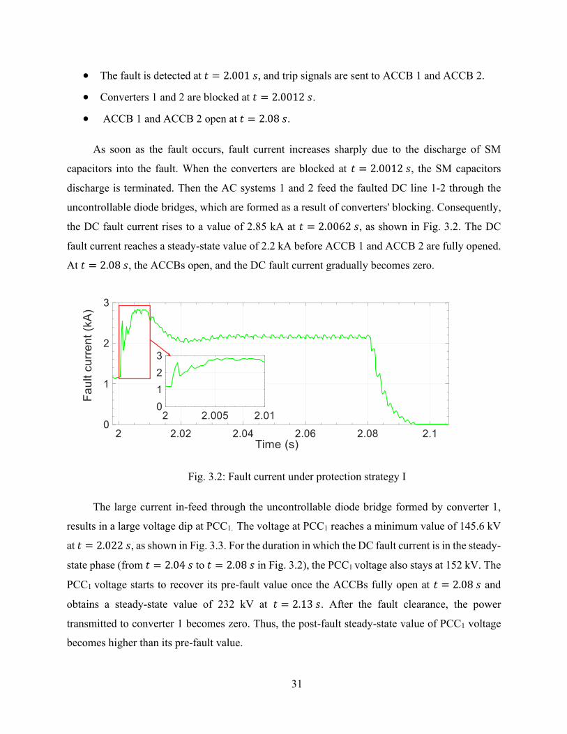
• The fault is detected at 𝑡 = 2.001 𝑠, and trip signals are sent to ACCB 1 and ACCB 2.
• Converters 1 and 2 are blocked at 𝑡 = 2.0012 𝑠.
• ACCB 1 and ACCB 2 open at 𝑡 = 2.08 𝑠.
As soon as the fault occurs, fault current increases sharply due to the discharge of SM
capacitors into the fault. When the converters are blocked at 𝑡 = 2.0012 𝑠, the SM capacitors
discharge is terminated. Then the AC systems 1 and 2 feed the faulted DC line 1-2 through the
uncontrollable diode bridges, which are formed as a result of converters' blocking. Consequently,
the DC fault current rises to a value of 2.85 kA at 𝑡 = 2.0062 𝑠, as shown in Fig. 3.2. The DC
fault current reaches a steady-state value of 2.2 kA before ACCB 1 and ACCB 2 are fully opened.
At 𝑡 = 2.08 𝑠, the ACCBs open, and the DC fault current gradually becomes zero.
Fig. 3.2: Fault current under protection strategy I
The large current in-feed through the uncontrollable diode bridge formed by converter 1,
results in a large voltage dip at PCC1. The voltage at PCC1 reaches a minimum value of 145.6 kV
at 𝑡 = 2.022 𝑠, as shown in Fig. 3.3. For the duration in which the DC fault current is in the steady-
state phase (from 𝑡 = 2.04 𝑠 to 𝑡 = 2.08 𝑠 in Fig. 3.2), the PCC1 voltage also stays at 152 kV. The
PCC1 voltage starts to recover its pre-fault value once the ACCBs fully open at 𝑡 = 2.08 𝑠 and
obtains a steady-state value of 232 kV at 𝑡 = 2.13 𝑠. After the fault clearance, the power
transmitted to converter 1 becomes zero. Thus, the post-fault steady-state value of PCC1 voltage
becomes higher than its pre-fault value.

32
Fig. 3.3: Voltage at PCC1 under protection strategy I
During the fault, the voltage at PCC1 falls and consequently, the active power transferred to
converter 3 drops. As converter 3 is operating under constant power control, it draws more current
from AC system1 to maintain the set-point value of the active power. Hence, the voltage at PCC1
decreases even more, and the active power drawn by converter 3 reduces until 𝑡 = 2.08 𝑠, as
shown in Fig. 3.4. Following the DC fault clearance at 𝑡 = 2.09 𝑠, converter 3 restores the injected
active power to the DC link at its pre-fault value, as shown in Fig. 3.4.
Fig. 3.4: Active power of converter 3 under protection strategy I

33
3.1.2 Case Study 2: HB-MMCs with DCCBs (Protection Strategy II)
Although protection strategies based on ACCBs are cheaper, they result in larger fault clearing
time and lack selectivity. The use of DCCBs eliminates these limitations. Bidirectional hybrid
DCCBs are installed at the two ends of the faulted DC line 1-2, as shown in Fig. 3.1. The operating
sequence of protection strategy II is as follows:
• The fault is applied to the middle of the DC line 1-2 at 𝑡 = 2 𝑠.
• The fault is detected at 𝑡 = 2.001 𝑠. Following a delay of 200 µs, trip signals are sent to
DCCB 1 and DCCB 2, and blocking signals are sent to converters 1 and 2.
• Converters 1 and 2 are blocked at 𝑡 = 2.0012 𝑠.
• The LCS is turned off, and the main breaker is turned on simultaneously at 𝑡 = 2.0012 𝑠.
As a result, the DC fault current starts to commutate into the main breaker branch.
• The UFD receives a trip signal at 𝑡 = 2.0012 𝑠 and fully opens at 𝑡 = 2.0032 𝑠.
• The main breaker is turned off once the UFD is fully opened at 𝑡 = 2.0032 𝑠.
• Following the opening of the main breaker, the DC fault current flows into the surge
arrester branch.
• The RCB opens at 𝑡 = 2.005 𝑠 once the fault current decays to zero.
After the fault occurrence, the fault current rises sharply and reaches a peak of 2.56 kA at
𝑡 = 2.0012 𝑠. At 𝑡 = 2.0012 𝑠, converters 1and 2 are blocked, hence the fault current decreases
gradually as it comprises of only the AC infeed current. At 𝑡 = 2.0012 𝑠, LCS is opened and the
current starts to commutate to the main breaker branch. Thus, the fault current again rises until the
main breaker branch is opened. At 𝑡 = 2.0032 𝑠, the main breaker branch is fully opened, and
the fault current falls sharply. The fault current becomes zero at 𝑡 = 2.005 𝑠, as shown in Fig. 3.5.

34
Fig. 3.5: Fault current under protection strategy II
Under protection strategy II, the PCC1 voltage is not affected severely as compared to that
under protection strategy I. The reason is that the DCCBs quickly isolate the fault. The quick
interruption of fault current leads to a lower peak value of the fault current, which accounts for a
smaller dip in PCC1 voltage. The PCC1 voltage reaches 205.4 kV at 𝑡 = 2.003 𝑠, as shown in Fig.
3.6. The rise of PCC1 voltage accompanies the reduction of fault current. Accordingly, the PCC1
voltage achieves a steady-state value of 232 kV within 30 ms of the fault isolation.
Fig. 3.6: Voltage at PCC1 under protection strategy II
Under protection strategy II, the active power supplied to converter 3 closely follows the
variations in the PCC1 voltage. The active power hits a minimum level of 582.5 MW at 𝑡 =
2.003 𝑠, as shown in Fig. 3.7. It is the same instant at which the PCC1 voltage approaches the

35
lowest value. After 𝑡 = 2.003 𝑠, the active power progressively rises and attains a peak value of
626.88 MW at 𝑡 = 2.0122 𝑠. The active power of converter 3 is restored to its set-point value
within 550 ms of the fault clearance.
Fig. 3.7: Active power of converter 3 under protection strategy II
3.1.3 Case Study 3: Augmented HB-MMCs with Graetz Bridges (Protection
Strategy III)
Although DCCBs are faster than ACCBs, DCCBs are more expensive and face a significant
challenge in the interruption capacity because the total amount of energy dissipation in surge
arresters of DCCBs could be large [58]. A modified converter configuration that combines a HB-
MMC and a Graetz bridge is proposed in [28] and [52] as a cost-effective solution for DC fault
clearance. The Graetz bridge bypasses the converter during DC faults. At each converter station,
a Graetz bridge is connected in parallel with the HB-MMC, as shown in Fig. 3.8. A hybrid switch
separates the DC sides of the HB-MMC and the Graetz bridge. The hybrid switch is a series
combination of LCS and UFD. The LCS is in parallel with a surge arrester to dissipate the residual
energy of the arm reactors when the LCS is switched off. The Graetz bridge is only operated during
the fault.

36
Fig. 3.8: The one-line diagram of the test system under protection strategy III
At 𝑡 = 2.0012 𝑠, the HB-MMC converter and the Graetz bridge are blocked and unblocked,
respectively. After the blocking of the HB-MMC, the converter acts like a three-phase diode
rectifier. If the thyristors in the Graetz bridge are fired at a minimum firing angle [28], then the
Graetz bridge will operate like a three-phase diode rectifier and will generate a positive DC
voltage. Therefore, both the HB-MMC and the Graetz bridge will produce similar voltages and
there will be a low voltage across the hybrid switch. Thus, the LCS can be formed from a few
series connected IGBTs [28]. The minimum firing angle used in this simulation is 5 degrees [42].
5 degrees corresponds to 0.232 ms in a 60 Hz system. This implies that the first thyristor in the
upper arm starts conducting 0.232 ms after receiving the unblocking signal. Moreover, there is a
60 degrees firing delay between the thyristors in the upper arm and the thyristors in the lower arm.
Hence, the second thyristor, which is in the lower arm and forms a return path for the current, starts
conducting 3.1 ms after receiving the unblocking signal. As a result, the Graetz bridge will
contribute to the fault current after 3.1 ms of being unblocked, which is at 𝑡 = 2.0043 𝑠. The LCS
should not be opened before 𝑡 = 2.0043 𝑠 [28]; otherwise, the LCS should interrupt a larger
current. Thus, in this simulation, a trip signal is sent to the LCS and UFD at 𝑡 = 2.006 𝑠. The
fastest UFD can fully open in 2 ms after receiving the trip signal. The UFD is fully opened at 𝑡 =
2.008 𝑠. Once the UFD is fully opened, the HB-MMC is completely isolated from the faulted DC
line, and it can be switched to the STATCOM mode. After the isolation of the HB-MMC from the
AC system
1
AC system
3
AC system
2
Line 1-2
Converter
3
Converter
4
Converter
2Converter
1PCC1
LDC LDC
Graetz bridge
2
Hybrid
switch 1
Hybrid
switch 2
ACCBACCBLine 3-4LDC LDCACCB ACCB
Graetz bridge
1
Graetz bridge
3
Graetz bridge
4
ACCB ACCBACCB ACCB
Hybrid
switch 4Hybrid
switch 3

37
DC side, a firing angle greater than 90 degrees ( here, the firing angle is 140 degrees) is applied to
the Graetz bridge so that it operates as an inverter. The negative DC voltage generated by the
Graetz bridge acts as a back-emf and takes the fault energy away, thereby reducing the fault current
to zero. Once the fault current is reduced to zero, the Graetz bridge is blocked. The operating
sequence under protection strategy III is as follows:
• The fault is applied to the middle of the DC line 1-2 at 2 s.
• The fault is detected at 𝑡 = 2.001 𝑠.
• Converters 1and 2 are blocked at 𝑡 = 2.0012 𝑠.
• Graetz bridges 1 and 2 are turned on as rectifiers with a firing angle of 5 degrees at 𝑡 =
2.0012 𝑠.
• LCS 1 and 2 receive trip signals and open at 𝑡 = 2.006 𝑠.
• UFD 1 and 2 receive trip signals at 𝑡 = 2.006 𝑠 and fully open at 𝑡 = 2.008 𝑠.
• Firing angles for Graetz bridges 1 and 2 are changed to 140 degrees at 𝑡 = 2.0082 𝑠. The
firing angles remain at 140 degrees until the fault is cleared.
• The fault is cleared at 𝑡 = 2.017 𝑠.
• Graetz bridges 1and 2 are blocked at 𝑡 = 2.017 𝑠.
Fig. 3.9 shows the waveform of DC fault current during the fault clearing process. The fault
current contributed by the Graetz bridge increases gradually after being fired at 5 degrees. The
fault current reaches a peak value of 3.03 kA. At 𝑡 = 2.0082 𝑠, the firing angle is changed to 140
degrees, and therefore, the output voltage of the Graetz bridge gradually becomes negative and
reaches a peak value of -290 kV at 𝑡 = 2.017 𝑠. In the meantime, the fault current decreases
smoothly and becomes zero at 𝑡 = 2.017 𝑠. The output voltage of the Graetz bridge undergoes
decaying oscillations and finally becomes zero at 𝑡 = 2.25 𝑠.

38
Fig. 3.9: Fault current under protection strategy III
Fig. 3.10 shows fault current sharing between converter 1 and Graetz bridge 1. Before the
opening of the hybrid switch, at 𝑡 = 2.005 𝑠, the fault current is 2.91 kA, where 1.07 kA is
provided by the Graetz bridge 1. After the opening of the hybrid switch at 𝑡 = 2.006 𝑠, the current
supplied by the blocked converter 1 decreases quickly to zero, and the current produced by the
Graetz bridge rises sharply. As compared to converter 1, Graetz bridge 1 offers a low impedance
path to the current due to the absence of arm reactors. When the UFD becomes fully open at 𝑡 =
2.008 𝑠, Converter 1 becomes isolated from the fault and the fault current is solely fed by the
Graetz bridge 1. As shown in Fig. 3.10, the UFD is opened under zero current condition and
therefore, it does not require an arc quenching medium. Thus, a fast-mechanical disconnector is
used as a UFD.
Fig. 3.10: Fault current contribution by converter 1 and Graetz bridge 1
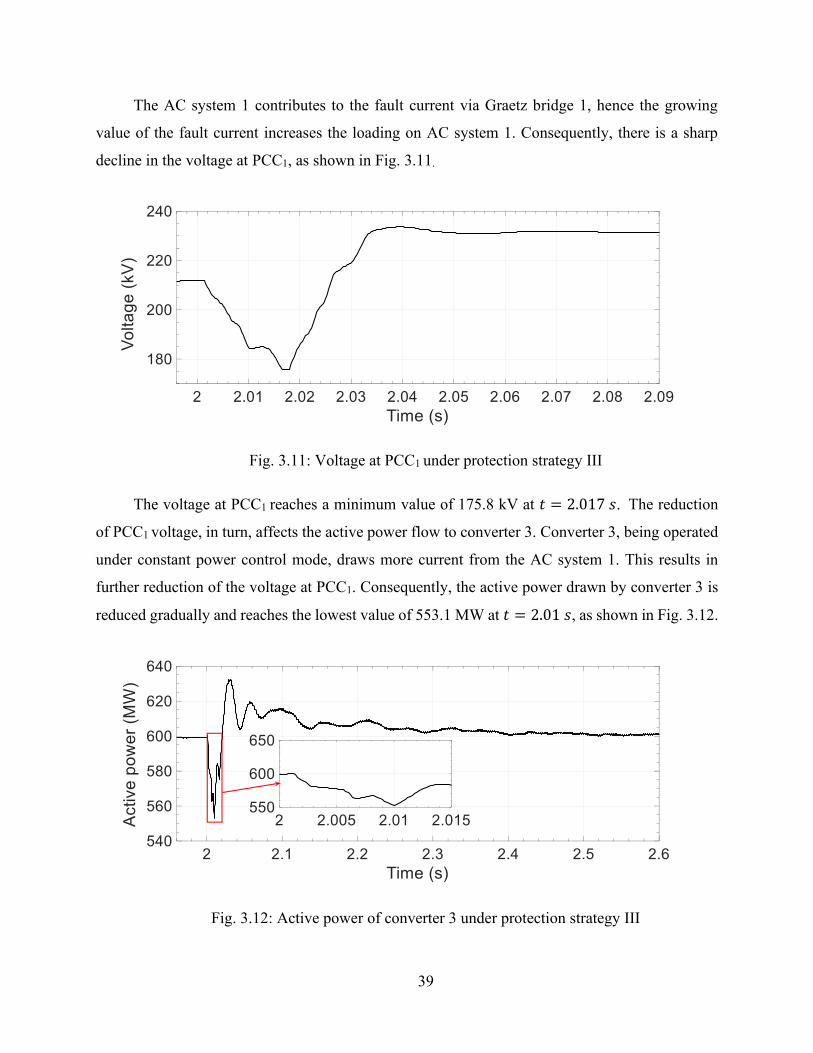
39
The AC system 1 contributes to the fault current via Graetz bridge 1, hence the growing
value of the fault current increases the loading on AC system 1. Consequently, there is a sharp
decline in the voltage at PCC1, as shown in Fig. 3.11.
Fig. 3.11: Voltage at PCC1 under protection strategy III
The voltage at PCC1 reaches a minimum value of 175.8 kV at 𝑡 = 2.017 𝑠. The reduction
of PCC1 voltage, in turn, affects the active power flow to converter 3. Converter 3, being operated
under constant power control mode, draws more current from the AC system 1. This results in
further reduction of the voltage at PCC1. Consequently, the active power drawn by converter 3 is
reduced gradually and reaches the lowest value of 553.1 MW at 𝑡 = 2.01 𝑠, as shown in Fig. 3.12.
Fig. 3.12: Active power of converter 3 under protection strategy III

40
At 𝑡 = 2.017 𝑠, the fault current reduces to zero and the PCC1 voltage starts to rise.
Consequently, the active power of converter 3 rises and returns to its pre-fault value. The PCC1
voltage reaches a steady-state value of 232 kV within 60 ms of the fault inception.
3.2 Comparison of the Three Protection Strategies
In this section, the three protection strategies are compared against each other by evaluating the
fault clearance time, peak values of the fault current, PCC voltage, and healthy converter’s active
power. Fig. 3.13 shows the DC fault current produced under the three protection strategies. The
highest peak of the fault current, which is 3.03 kA, corresponds to protection strategy III, while
the lowest peak of the fault current is 2.56 kA (under protection strategy II). The peak of the fault
current under protection strategies I and III is 11.42% and 18.63% more than that under protection
strategy II, respectively. The largest fault clearance time, which is 93.3 ms, corresponds to
protection strategy I. In contrast, the shortest fault clearance time is 5 ms which corresponds to
protection strategy II. The fault clearance time under protection strategies I and III is 4.4% and
0.57% higher than that under protection strategy II, respectively. Considering both the fault
clearance time and the peak fault current, the protection strategy II outperforms the other two
strategies. Although the protection strategy III has a higher peak fault current than protection
strategy I, the former strategy allows the current to decay quickly to zero. As observed in section
3.1, the faster the fault current decays to zero, the sooner the healthy converter restores its pre-
fault operation.
Fig. 3.14 shows the active power of converter 3 under the three protection strategies. The
highest settling time is 293 ms, which corresponds to protection strategy I, while the lowest settling
time is 63 ms, which corresponds to protection strategy II. The settling time of active power under
protection strategies I and III is 11.15% and 2.57% higher than that under protection strategy II,
respectively.

41
Fig. 3.13: Fault current under the three protection strategies
Fig. 3.14: Active power of converter 3 under the three protection strategies
After the removal of fault in each of the three protection strategies, the active power
gradually rises. Under protection strategy I, the highest peak of 651 MW is obtained before the
active power is restored to its set-point value. On the other hand, the lowest peak of 626.88 MW
is obtained under protection strategy II. The peak power under protection strategies I and III is
3.85% and 0.91% higher than that under protection strategy II.
Following an increase in the active power, the DC side current of converter 3 is increased
temporarily. In case of a weak AC system, the DC current of healthy converter may exceed the
pickup value of the converter's internal protection to prevent damages to the IGBTs. This may
result in an undesirable blocking of the healthy converter. Hence, considering the peak value and

42
settling time of the active power of converter 3, the protection strategy II outperforms the other
two strategies. Also, protection strategy III has a better performance than protection strategy I.
Fig. 3.15 shows the voltage at PCC1 under the three protection strategies. The highest settling
time, which is 103 ms, is obtained under protection strategy I, while the lowest settling time of
25.5 ms is attained under protection strategy II. The settling time of PCC1 voltage under protection
strategies I and III is 3.83% and 0.86 % higher than that under protection strategy II, respectively.
After fault clearance, the steady-state value of PCC1 voltage is the same in the three protection
strategies.
Fig. 3.15: Voltage at PCC1 under the three protection strategies
The lowest value of the PCC1 voltage, which is 145.6 kV, is obtained under protection
strategy I, while the smallest voltage dip of 205.4 kV is obtained under protection strategy II. The
voltage dip under protection strategies I and III is 29.11% and 14.4% more than that under
protection strategy II, respectively. A larger voltage dip results in a larger current drawn by
converter 3 from AC system 1 to maintain the active power at the pre-fault setpoint value.
Considering the voltage dip and settling time of voltage at PCC1, the protection strategy II
outperforms the other two strategies. Also, protection strategy III has a better performance than
the protection strategy I.
The DCCBs used in protection strategy II, consist of four essential components: LCS, UFD,
the main breaker, and the surge arrester. On the other hand, the hybrid switch, which is utilized in
protection strategy III, consists of LCS, UFD, and the surge arrester. The hybrid switch does not

43
need a main breaker branch because it is not required to break the fault current. It only needs to
disconnect the HB-MMC from the Graetz bridge. The absence of the main breaker reduces the
cost and footprint of the hybrid switch as compared to that of the DCCB.
The main breaker of the DCCB receives a trip signal at 𝑡 = 2.0032 𝑠 to break a current of
2.3 kA while the LCS of the hybrid switch receives a trip signal at 𝑡 = 2.006 𝑠 to interrupt a
current of 1.3 kA, as shown in Fig. 3.16. The higher the value of breaking current, the higher
should be the rated voltage of the surge arrester to attain a faster decay of the fault current [28],
[55]. Also, the energy dissipated in the surge arresters of DCCBs is higher than the surge arresters
of the hybrid switch.
Fig. 3.16: Current through the hybrid switch and the DCCB
However, the higher voltage rating of the surge arrester leads to a higher switching
overvoltage in a DCCB compared to a hybrid switch [43], as shown in Fig. 3.17. In this simulation,
360 kV and 240 kV are the rated voltages for the surge arrester of DCCB and hybrid switch,
respectively. As shown in Fig. 3.17, the DCCB is subjected to an overvoltage of 660 kV, whereas,
the hybrid switch experiences an overvoltage of 440 kV. Hence, the switches in the main breaker
of the DCCB should have a higher blocking voltage than the switches in the hybrid switch. It can
be concluded that the hybrid switch has lower power losses and is more economical than the
DCCB.

44
Fig. 3.17: Voltage across the hybrid switch and the DCCB during fault clearance
3.3 HB-MMCs Operation as a STATCOM During DC Faults
A STATCOM is capable of generating or absorbing reactive power to support the PCC voltage.
The voltage at PCC is affected by a fault on the DC link. The investigations in section 3.1 reveal
that a reduction in the PCC voltage due to a DC fault reduces the active power flow to the healthy
converter. If the faulted converter can operate as a STATCOM to provide reactive power support
to the grid, it can improve the operation of the healthy converter during the fault.
In this section, the HB-MMC connected to the faulted DC line is operated as a STATCOM
after being isolated from the fault. The impact of the faulted converter operation as a STATCOM
on the PCC and the healthy converter is evaluated by analyzing the waveforms of voltage at PCC
and power flow of the healthy converter under protection strategies II and III. Protection strategy
I is not considered in this analysis because this strategy does not allow the faulted converter to
operate as a STATCOM during fault clearance as the converter is disconnected from the AC
system.
3.3.1 Case Study 1: STATCOM Mode I Strategy
In this study, the operation of converter 1 as a STATCOM is investigated when the protection
strategy II is used for fault clearance. The sequence of the events is as follows:

45
• The fault is applied to the middle of the DC line 1-2 at 𝑡 = 2 𝑠.
• The fault is detected at 𝑡 = 2.001 𝑠. Following a delay of 200 µs, trip signals are sent to
DCCB 1 and DCCB 2, and blocking signals are sent to converters 1and 2.
• Converters 1 and 2 are blocked at 𝑡 = 2.0012 𝑠.
• The LCS is turned off, and the main breaker is turned on simultaneously at 𝑡 = 2.0012 𝑠.
As a result, the DC fault current starts to commutate into the main breaker branch.
• The UFD receives a trip signal at 𝑡 = 2.0012 𝑠 and fully opens at 𝑡 = 2.0032 𝑠.
• Following the opening of the main breaker, the DC fault current flows into the surge
arrester branch.
• The RCB opens at 𝑡 = 2.005 𝑠 when the fault current reaches zero and converters 1 and 2
become fully isolated from the fault.
• After a delay of 400 µs, at 𝑡 = 2.0054 𝑠, a deblocking signal is sent to converter 1. At the
same instant, the operation mode of converter 1 is changed from active/reactive power
control mode to active power/AC voltage control mode. The set-point of active power is
changed to zero and the converter controls the AC voltage.
Since converter 1 is operated as a STATCOM after the fault clearance, the fault current under
protection strategy II and STATCOM mode I is identical as shown in Fig. 3.18.
Fig. 3.18: Fault current under protection strategy II and STATCOM mode I strategy

46
Under the STATCOM mode I strategy, converter 1 absorbs a reactive power of 240 Mvar
from AC system 1, and PCC1 voltage is restored to its pre-fault value of 211.6 kV within 500 ms
of the fault occurrence, as shown in Fig. 3.19. The PCC1 voltage reaches a minimum value of
205.5 kV at 𝑡 = 2.003 𝑠. The PCC1 voltage reaches a peak value of 225.80 kV at 𝑡 = 2.07 𝑠.
Under protection strategy II, the PCC1 voltage is not restored to its pre-fault value, Fig. 3.19.
Fig. 3.19: PCC1 voltage under protection strategy II and STATCOM mode I strategy
Under the STATCOM mode I strategy, the active power of converter 3 reaches its set-point
value of 600 MW within 300 ms of the fault occurrence, while it is restored to its pre-fault value
within 550 ms of the fault occurrence under protection strategy II, Fig. 3.20.
Fig. 3.20: Active power of converter 3 under protection strategy II and STATCOM mode I
strategy

47
3.3.2 Case Study 2: STATCOM Mode II Strategy
In this section, the operation of converter 1 as a STATCOM is investigated when protection
strategy III is used for fault clearance. The sequence of operations is summarized as follows:
• The fault is applied to the middle of the DC line 1-2 at 𝑡 = 2 𝑠.
• The fault is detected at 𝑡 = 2.001 𝑠.
• Converters 1and 2 are blocked at 𝑡 = 2.0012 𝑠.
• Graetz bridges 1 and 2 are turned on as rectifiers with a firing angle of 5 degrees at 𝑡 =
2.0012 𝑠.
• LCS 1 and 2 receive the trip signals and open at 𝑡 = 2.006 𝑠.
• UFD 1 and 2 receive the trip signals and fully open at 𝑡 = 2.008 𝑠.
• Firing angles for Graetz bridges 1 and 2 are changed to 140 degrees at 𝑡 = 2.0082 𝑠.
The firing angles remain at 140 degrees until the fault is cleared.
• At 𝑡 = 2.0082 𝑠, a deblocking signal is sent to converter 1 and the operation mode of
converter 1 is changed from active/reactive power control to active power/AC voltage
control. The set-point of power is also changed to zero.
• The fault is cleared at 𝑡 = 2.0172 𝑠.
• Graetz bridges 1and 2 are turned off at 𝑡 = 2.0172 𝑠.
Under the STATCOM mode II strategy, converter 1 absorbs a reactive power of 240 Mvar
from AC system 1 and PCC1 voltage is restored to its pre-fault value of 211.6 kV within 500 ms
of the fault occurrence, Fig. 3.21. PCC1 voltage reaches a minimum value of 196.7 kV at 𝑡 =
2.009 𝑠. However, under protection strategy III, the PCC1 voltage reaches a minimum value of
175.8 kV at 𝑡 = 2.017 𝑠 and never regains its pre-fault value. Under the STATCOM mode II
strategy, the active power of healthy converter 3 reaches a peak value of 655.47 MW at 𝑡 = 2.02 𝑠
and reaches its set-point value of 600 MW within 400 ms of the fault occurrence, Fig. 3.22. Under
protection strategy III, the active power of converter 3 reaches its pre-fault value after 550 ms of
the fault occurrence, Fig. 3.22.

48
Fig. 3.21: PCC1 voltage under protection strategy III and STATCOM mode II strategy
Fig. 3.22: Active power of converter 3 under protection strategy III and STATCOM mode II
strategy
Under the STATCOM mode II strategy, due to the increase in the PCC1 voltage, the peak
value of fault current is 28.38 % higher than that obtained under protection strategy III, Figs. 3.23
and 3.24. Despite a higher fault current under the STATCOM mode II strategy, the duration of
fault clearance under both strategies is almost the same due to the higher negative peak voltage
produced by Graetz bridge 1 under the STATCOM mode II strategy.

49
Fig. 3.23: Fault current under STATCOM mode II strategy
Fig. 3.24: Graetz bridge’s output current under protection strategy III and STATCOM mode II
strategy
3.3.3 Comparison of STATCOM Mode I and II Strategies
The PCC1 voltage during fault clearance under STATCOM mode I and II strategies is shown in
Fig. 3.25. The PCC1 voltage experiences larger oscillations under STATCOM mode I. Moreover,
the peak value of the fault current and active power under the STATCOM mode II strategy is
significantly larger than the peak value under the STATCOM mode I strategy, Figs. 3.26 and 3.27.
Furthermore, the active power of healthy converter 3 approaches its set-point value faster under
the STATCOM mode I strategy, Fig. 3.27.

50
Fig. 3.25: PCC1 voltage under STATCOM mode I and II strategies
Fig. 3.26: Fault current under STATCOM mode I and II strategies
Fig. 3.27: Active power of converter 3 under STATCOM modes I and II strategies

51
3.4 Summary
In this chapter, the impact of faulted converter on the performance of healthy converter under three
protection strategies based on ACCBs, DCCBs and augmented HB-MMCs was analyzed. The
STATCOM operation of a converter connected to a faulted DC line under different protection
strategies was also studied in this chapter. The impact of STATCOM operation of the faulted
converter, under different protection strategies, on the electrically close healthy converter and PCC
was also investigated. The findings of the chapter are summarized in Table 3.1.
Table 3.1: Comparison of different protection strategies and STATCOM mode strategies
Protection strategy I
Protection strategy II
Protection strategy
III
STATCOM mode I
STATCOM
mode II
Maximum DC fault current 2.85 kA 2.56 kA 3.03 kA 2.56 kA
3.89 kA
Fault clearance time 93.3 ms 5 ms 17 ms 5 ms
17.2 ms
Minimum PCC voltage 145.6 kV 205.4 kV 175.8 kV 205.5 kV
196.7 kV
PCC voltage post-fault steady-state value
Higher
than the
pre-fault
value
Higher
than the
pre-fault
value
Higher
than the
pre-fault
value
Equal to
the pre-
fault value
Equal to
the pre-
fault value
Active power settling time (healthy converter)
293 ms 63 ms 64.62 ms 95 ms
46 ms
Cost and footprint of the DCCB
Not
applicable High
Not
applicable
Not
applicable
Not
applicable
Cost and footprint of the hybrid switch
Not
applicable
Not
applicable Low
Not
applicable
Not
applicable
Selectivity No Yes Yes Yes
Yes
Converter operation as a STATCOM during fault
clearance
Not
possible Possible Possible Possible
Possible

52
Chapter 4 Conclusion
4.1 Conclusions
In modern power systems, HVDC transmission systems are being transformed from point-to-point
configurations towards the more economical and reliable multiterminal configurations. In the
multiterminal configuration, converters are located electrically close to each other and an AC grid
can have more than one converter connected to it. Furthermore, the large integration of inverter-
based renewable sources may result in converters that are located electrically close to each other
and consequently interact with each other. Thus, in systems with multiple converters in close
proximity, a fault occurring on one DC link will affect the healthy converters connected to the
same PCC. The type of protection strategy used on the faulted link will influence the PCC voltage
and hence the healthy converters connected to that PCC. However, if the converter connected to
the faulted DC link can be operated as a STATCOM to support PCC voltage, then the impact of
the DC fault on the electrically close healthy converters is reduced. However, not all converters
can be operated as a STATCOM. In general, the protection strategy selected for the HVDC system
will significantly affect the level of impact of a faulty converter on the healthy converters.
A large number of protection strategies based on ACCBs, DCCBs, fault blocking converters,
and augmented HB-MMCs with thyristors are proposed in the literature for the protection of
HVDC systems. ACCBs are widely used to protect the point-to-point HVDC systems because they
provide the most economical solution for DC fault protection. However, the fault clearance time
of ACCBs is the largest among all other protection strategies. Moreover, the faulted converter
cannot be operated as a STATCOM during the fault clearance process if ACCBs are used for fault
isolation. This is because the converters are blocked during the fault to protect the IGBTs against
excessive overcurrent owing to a relatively higher fault clearance time of the ACCBs. Protection
strategies using DCCBs are the fastest to clear the fault, but at the same time, they are expensive.
Furthermore, the faulted converter can be operated in STATCOM mode because the converter
may stay unblocked during the fault clearance as the quick operation of the DCCBs may prevent
the arm current from exceeding its threshold value. Furthermore, after fault isolation, the faulty
53
converter will be fully isolated from the DC system and can reliably operate as a STATCOM.
Protection strategies using fault blocking converters interrupt the DC fault current without using
ACCBs or DCCBs. Furthermore, fault blocking converters can operate as a STATCOM during
the fault clearance as the converter can remain unblocked. However, these converters have higher
conduction losses and higher costs than HB-MMCs. There are several converter topologies based
on HBSMs proposed in the literature that can be used to interrupt the fault current without the need
for the operation of ACCBs or DCCBs. These converters are comprised of HBSMs and are
augmented with thyristors. Studies show that with augmented HB-MMCs, DC faults can be cleared
without using ACCBs or DCCBs. These augmented HB-MMCs can be formed by adding a pair
of antiparallel thyristors to each HBSM, combining and connecting pairs of antiparallel thyristors
on the AC side of HB-MMCs, or connecting Graetz bridges in parallel to HB-MMCs.
Nevertheless, the STATCOM operation of the faulted converter is only possible in HB-MMCs
augmented with Graetz bridges as the other thyristor-based configurations require the converter to
remain blocked throughout the fault clearance process.
This thesis focuses on HVDC systems with HB-MMCs, which have lower conduction losses
and less expensive SMs, and considers three different protection strategies based on ACCBs
(protection strategy I), DCCBs (protection strategy II), and augmented HB-MMCs with Graetz
bridges (protection strategy III). This thesis investigates and compares the impact of protection
strategies I, II, and III on the PCC voltage and the healthy converter, which is in close proximity
to a converter feeding the faulted DC link. The waveforms for fault current, PCC voltage, and
active power of the healthy converter are examined and compared. The study reveals that
protection strategy II is the most suitable strategy as compared to strategies I and III because it
produces the least impact on PCC voltage and active power of the healthy converter, and provides
the fastest fault clearance. Similarly, protection strategy III affects the PCC voltage and active
power of the healthy converter to a lesser extent and clears the fault faster than protection strategy
I. Unlike, protection strategy I, protection strategy III provides selectivity. Hence, protection
strategy III has an improved performance than protection strategy I. Furthermore, surge arresters
in DCCBs of protection strategy II are required to dissipate higher energy amounts than the surge
arresters in the hybrid switches of protection strategy III.
This thesis also evaluates the impact of the discussed protection strategies on the PCC

54
voltage and the active power of the healthy converter when a converter connected to the faulted
DC link is operated as a STATCOM after being isolated from the faulted link. The STATCOM
mode of the converter is analyzed and compared under protection strategies II and III and has been
referred to as STATCOM mode I and II strategies, respectively. It has been found that protection
strategy III enables the converter to switch to the STATCOM mode before the clearance of fault.
However, faster restoration of the active power of a healthy converter to its pre-fault set-point
value is achieved in STATCOM mode I. Moreover, in STATCOM mode I and II strategies, the
pre-fault value of PCC voltage is attained at the same time. Without the STATCOM mode of
operation, the PCC voltage does not reach its pre-fault value and the power flow through the
healthy link takes a longer time to reach the pre-fault value.
4.2 Thesis Contributions
The contributions of this thesis are summarized as follows:
1. The performance of three different protection strategies is evaluated by comparing the fault
clearance time.
2. The comparison of the impact of the three protection strategies on the PCC voltage and the
active power of electrically close healthy converter is conducted.
3. Analysis and comparison of the support provided to the healthy converter when the
converter connected to the faulted DC link acts as a STATCOM are conducted by
modifying protection strategies II and III.
4.3 Future Work
A list of future works is as follows:
1. To evaluate the impact of faulty converters on the operation of healthy converters in MTDC
systems.
2. To modify protection strategy III by connecting two Graetz bridges in series to form a 12-
pulse bridge, which generates a higher output voltage than a single Graetz bridge. Then,

55
the fault response under modified protection strategy III and the impact on healthy
converters in close proximity to a converter feeding a faulted DC link will be investigated.
3. To compare the impact of the restoration of the faulted link, under all the three protection
strategies, on the healthy converters in close proximity.
56
Bibliography
[1] “Powering our future with clean electricity,” Government of Canada, Dec. 12, 2018.
[online]. Available:
https://www.canada.ca/en/services/environment/weather/climatechange/climate-
action/powering-future-clean-energy.html
[2] J. MacDowell et al., "A Journey Through Energy Systems Integration: Trending Grid
Codes, Standards, and IEC Collaboration," in IEEE Power and Energy Magazine, vol.
17, no. 6, pp. 79-88, Nov.-Dec. 2019.
[3] L. Kunjumuhammed, S. Kuenzel, and B. Pal, Simulation of Power System with
Renewables. Academic Press, 2020.
[4] B. K. Bose, Power Electronics in Renewable Energy Systems and Smart Grid:
Technology and Applications. Wiley-IEEE Press, 2019.
[5] D. Van Hertem et al., "Substations for Future HVdc Grids: Equipment and
Configurations for Connection of HVdc Network Elements," in IEEE Power and
Energy Magazine, vol. 17, no. 4, pp. 56-66, July-Aug. 2019.
[6] B. R. T. Cotts, J. R. Prigmore and K. L. Graf, "6 - HVDC Transmission for Renewable
Energy Integration," The Power Grid, pp. 171-196. Academic Press, 2017.
[7] D. Van Hertem, O. Gomis-Bellmunt and J. Liang, HVDC Grids: For Offshore and
Supergrid of the Future. John Wiley & Sons, 2016.
[8] J. Freytes et al., "Dynamic Analysis of MMC-Based MTDC Grids: Use of MMC
Energy to Improve Voltage Behavior," in IEEE Transactions on Power Delivery, vol.
34, no. 1, pp. 137-148, Feb. 2019.

57
[9] Y. Liu, T. C. Green, J. Wu, K. Rouzbehi, A. Raza and D. Xu, "A New Droop
Coefficient Design Method for Accurate Power-Sharing in VSC-MTDC Systems,"
in IEEE Access, vol. 7, pp. 47605-47614, 2019.
[10] A. M. Trzynadlowski, Power Electronic Converters and Systems - Frontiers and
Applications. Institution of Engineering and Technology, 2016.
[11] D. Jovcic, High Voltage Direct Current Transmission: Converters, Systems and DC
Grids. (Second ed.) John Wiley & Sons, 2020.
[12] M. N. Raju et al, "Modular multilevel converters technology: a comprehensive study
on its topologies, modelling, control and applications," IET Power Electronics, vol.
12, (2), pp. 149-169, 2019.
[13] S. Wang, C. Li, O. D. Adeuyi, G. Li, C. E. Ugalde-Loo and J. Liang, "Coordination of
MMCs With Hybrid DC Circuit Breakers for HVDC Grid Protection," in IEEE
Transactions on Power Delivery, vol. 34, no. 1, pp. 11-22, Feb. 2019.
[14] Y. Guo, G. Wang, D. Zeng, H. Li and H. Chao, "A Thyristor Full-Bridge-Based DC
Circuit Breaker," in IEEE Transactions on Power Electronics, vol. 35, no. 1, pp. 1111-
1123, Jan. 2020.
[15] J. Sun, M. Saeedifard and A. P. S. Meliopoulos, "Backup Protection of Multi-Terminal
HVDC Grids Based on Quickest Change Detection," in IEEE Transactions on Power
Delivery, vol. 34, no. 1, pp. 177-187, Feb. 2019.
[16] Y. Luo, P. Yi, X. Xiaofu, W. Jiang and S. Yonghui, "DC fault ride-through method
for full-bridge MMC-based MTDC systems," in The Journal of Engineering, vol.
2019, no. 16, pp. 3175-3179, 2019.
[17] K. Givaki, M. H. Rahman, D. Vozikis and A. Giveki, "Analysis of integration of multi-
terminal HVDC network to weak grids," in The Journal of Engineering, vol. 2019, no.
16, pp. 3219-3224, 2019.

58
[18] S. Du, A. Dekka, B. Wu, and N. Zargari, Modular Multilevel Converters: Analysis,
Control, and Applications. (First ed.) John Wiley & Sons, 2018.
[19] C.C. Davidson et al., “Mitigating the Interaction Between VSC-HVDC Links When
One Link is Subject to a DC Line Fault,” in CIGRE Winnipeg Colloquium, 2017.
[20] G. Tang, Z. Xu and Y. Zhou, "Impacts of Three MMC-HVDC Configurations on AC
System Stability Under DC Line Faults," in IEEE Transactions on Power Systems,
vol. 29, no. 6, pp. 3030-3040, Nov. 2014.
[21] P. Ruffing, N. Collath, C. Brantl and A. Schnettler, "DC Fault Control and High-Speed
Switch Design for an HVDC Network Protection Based on Fault-Blocking
Converters," in IEEE Transactions on Power Delivery, vol. 34, no. 1, pp. 397-406,
Feb. 2019.
[22] S. Cao, W. Xiang, X. Lu, W. Ling and J. Wen, "A DC fault ride-through and energy
dissipation scheme for hybrid MMC-MTDC integrating wind farms with overhead
lines," in The Journal of Engineering, vol. 2019, no. 18, pp. 4804-4808, 2019.
[23] S. Wang, (2016), Control and Protection of HVDC Grids, Ph. D. Thesis, Cardiff
University.
[24] B. Xiang et al., "Arcing Time of a DC Circuit Breaker Based on a Superconducting
Current-Limiting Technology," in IEEE Transactions on Applied
Superconductivity, vol. 26, no. 7, pp. 1-5, Oct. 2016.
[25] Mokhberdoran, D. Van Hertem, N. Silva, H. Leite and A. Carvalho, "Multiport Hybrid
HVDC Circuit Breaker," in IEEE Transactions on Industrial Electronics, vol. 65,
no.1, pp. 309-320, Jan. 2018.
[26] M. K. Bucher and C. M. Franck, "Fault Current Interruption in Multiterminal HVDC
Networks," in IEEE Transactions on Power Delivery, vol. 31, no. 1, pp. 87-95, Feb.
2016.

59
[27] A. Shukla and G. D. Demetriades, "A Survey on Hybrid Circuit-Breaker Topologies,"
in IEEE Transactions on Power Delivery, vol. 30, no. 2, pp. 627-641, April 2015.
[28] I. A. Gowaid, "A Low-Loss Hybrid Bypass for DC Fault Protection of Modular
Multilevel Converters," in IEEE Transactions on Power Delivery, vol. 32, no. 2, pp.
599-608, April 2017.
[29] D. Jovcic, M. Zaja and M. H. Hedayati, "Bidirectional Hybrid HVDC CB With a
Single HV Valve," in IEEE Transactions on Power Delivery, vol. 35, no. 1, pp. 269-
277, Feb. 2020.
[30] J. Hu, R. Zeng and Z. He, "DC fault ride-through of MMCs for HVDC systems: a
review," in The Journal of Engineering, vol. 2016, no. 9, pp. 321-331, 2016.
[31] T. H. Nguyen, K. A. Hosani, M. S. E. Moursi and F. Blaabjerg, "An Overview of
Modular Multilevel Converters in HVDC Transmission Systems With STATCOM
Operation During Pole-to-Pole DC Short Circuits," in IEEE Transactions on Power
Electronics, vol. 34, no. 5, pp. 4137-4160, May 2019.
[32] O. Cwikowski, H. R. Wickramasinghe, G. Konstantinou, J. Pou, M. Barnes and R.
Shuttleworth, "Modular Multilevel Converter DC Fault Protection," in IEEE
Transactions on Power Delivery, vol. 33, no. 1, pp. 291-300, Feb. 2018.
[33] J. Liu, N. Tai and C. Fan, "Transient-Voltage-Based Protection Scheme for DC Line
Faults in the Multiterminal VSC-HVDC System," in IEEE Transactions on Power
Delivery, vol. 32, no. 3, pp. 1483-1494, June 2017.
[34] J. Qin, M. Saeedifard, A. Rockhill and R. Zhou, "Hybrid Design of Modular Multilevel
Converters for HVDC Systems Based on Various Submodule Circuits," in IEEE
Transactions on Power Delivery, vol. 30, no. 1, pp. 385-394, Feb. 2015.
[35] R. Zeng, L. Xu, L. Yao and B. W. Williams, "Design and Operation of a Hybrid
Modular Multilevel Converter," in IEEE Transactions on Power Electronics, vol. 30,
no. 3, pp. 1137-1146, March 2015.

60
[36] Y. Wan, M. Mao, L. Zhou, X. Xi, B. Xie and S. Zhou, "Review on topology-based dc
short-circuit fault ride-through strategies for MMC-based HVDC system," in IET
Power Electronics, vol. 13, no. 2, pp. 203-220, 2020.
[37] X. Li, Q. Song, W. Liu, H. Rao, S. Xu and L. Li, "Protection of Nonpermanent Faults
on DC Overhead Lines in MMC-Based HVDC Systems," in IEEE Transactions on
Power Delivery, vol. 28, no. 1, pp. 483-490, Jan. 2013.
[38] J. Liao, N. Zhou, Q. Wang and Y. Luo, "A Bypass LCC-Based DC Fault Isolation
Scheme for Bipolar MMC–HVDC," in IEEE Access, vol. 7, pp. 118218-118228, 2019.
[39] G. P. Chaffey, (2017), The Impact of Fault Blocking Converters on HVDC Protection,
Ph. D. Thesis, Imperial College London.
[40] X. Yang, Y. Xue, P. Wen and Z. Li, "Comprehensive understanding of DC pole-to-
pole fault and its protection for modular multilevel converters," in High Voltage, vol.
3, no. 4, pp. 246-254, 2018.
[41] A. A. Elserougi, A. S. Abdel-Khalik, A. M. Massoud and S. Ahmed, "A New
Protection Scheme for HVDC Converters Against DC-Side Faults With Current
Suppression Capability," in IEEE Transactions on Power Delivery, vol. 29, no. 4, pp.
1569-1577, Aug. 2014.
[42] M. H. Rashid, Power Electronics Handbook. (Fourth ed.) Butterworth-Heinemann,
2018.
[43] G. Li, (2017), Analysis and Protection of HVDC Systems Subject to AC and DC Faults,
Ph. D. Thesis, Cardiff University.
[44] N. Ahmed, L. Ängquist, S. Norrga, A. Antonopoulos, L. Harnefors and H. Nee, "A
Computationally Efficient Continuous Model for the Modular Multilevel Converter,"
in IEEE Journal of Emerging and Selected Topics in Power Electronics, vol. 2, no. 4,
pp. 1139-1148, Dec. 2014.

61
[45] CIGRE Brochure 604 (Working group B4.57), “Guide for the Development of Models
for HVDC Converters in a HVDC Grid”, Dec 2014.
[46] D. Guo et al., "Detailed quantitative comparison of half-bridge modular multilevel
converter modelling methods," in The Journal of Engineering, vol. 2019, no. 16, pp.
1292-1298, 3 2019.
[47] H. Saad, C. Dufour, J. Mahseredjian, S. Dennetière, S. Nguefeu, “Real Time
simulation of MMCs using the State-Space Nodal Approach", International
Conference on Power Systems Transients, Vancouver, BC, Canada, July 2013.
[48] K. Sharifabadi et al, Design, Control and Application of Modular Multilevel
Converters for HVDC Transmission Systems. John Wiley & Sons, 2016.
[49] U. N. Gnanarathna, A. M. Gole and R. P. Jayasinghe, "Efficient Modeling of Modular
Multilevel HVDC Converters (MMC) on Electromagnetic Transient Simulation
Programs," in IEEE Transactions on Power Delivery, vol. 26, no. 1, pp. 316-324, Jan.
2011.
[50] J. De Silva, L. Kothalawala, “Modelling Cables and Transmission Lines with
PSCAD/EMTDC: A webinar on modelling cables and transmission lines with
PSCAD,” October 27, 2016. Retrieved from https://www.pscad.com/knowledge-
base/article/363
[51] F. Deng and Z. Chen, "Voltage-Balancing Method for Modular Multilevel Converters
Under Phase-Shifted Carrier-Based Pulsewidth Modulation," in IEEE Transactions on
Industrial Electronics, vol. 62, no. 7, pp. 4158-4169, July 2015.
[52] M. Saeedifard and R. Iravani, "Dynamic Performance of a Modular Multilevel Back-
to-Back HVDC System," in IEEE Transactions on Power Delivery, vol. 25, no. 4, pp.
2903-2912, Oct. 2010.
62
[53] CIGRE, “Modelling and Simulation Studies to be performed during the lifecycle of
HVDC Systems,” CIGRE WG B4.38, 563, December 2013.
[54] J. Häfner and B. Jacobson, "Proactive Hybrid HVDC Breakers-A key innovation for
reliable HVDC grids," in CIGRE symposium, Bologna, 2011.
[55] N. R. Chaudhuri, B. Chaudhuri, R. Majumder and A. Yazdani, Multi-terminal Direct-
Current Grids: Modeling, Analysis, and Control. (First ed.) John Wiley & Sons, 2014.
[56] W. Leterme, (2016), Communication-less Protection Algorithms for Meshed VSC
HVDC Cable Grids, Ph.D. Thesis, Ku Leuven.
[57] E. Kontos, G. Tsolaridis, R. Teodorescu and P. Bauer, "On DC Fault Dynamics of
MMC-Based HVdc Connections," in IEEE Transactions on Power Delivery, vol. 33,
no. 1, pp. 497-507, Feb. 2018.
[58] J. Xu, X. Zhao, H. Jing, J. Liang and C. Zhao, "DC Fault Current Clearance at the
Source Side of HVDC Grid Using Hybrid MMC," in IEEE Transactions on Power
Delivery, vol. 35, no. 1, pp. 140-149, Feb. 2020.