Embed Size (px)
Citation preview
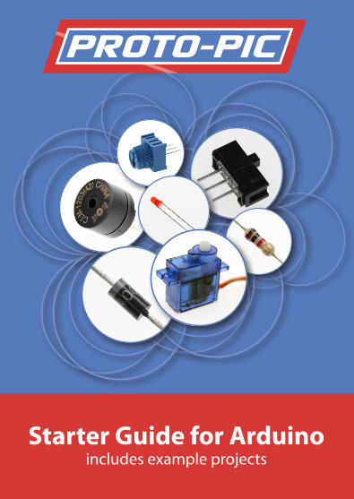
Proto-PIC
Starter Guide for Arduinoincludes example projects
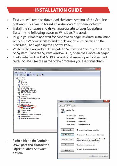
• FirstyouwillneedtodownloadthelatestversionoftheArduinosoftware.Thiscanbefoundat:arduino.cc/en/main/software.
• InstallthesoftwareanddriverappropriatetoyourOperatingSystem-thefollowingassumesWindows7isused.
• PluginyourboardandwaitforWindowstobeginitsdriverinstallationprocess.IfWindowsfailstofindthedevicedriverthenclickontheStartMenuandopenuptheControlPanel.
• WhileintheControlPanelnavigatetoSystemandSecurity.Next,clickonSystem.OncetheSystemwindowisup,opentheDeviceManager.
• LookunderPorts(COM&LPT).Youshouldseeanopenportnamed“ArduinoUNO”(orthenameoftheprocessoryouareconnecting)
• Rightclickonthe“ArduinoUNO”portandchoosethe“UpdateDriverSoftware”option.
INSTALLATION GUIDE
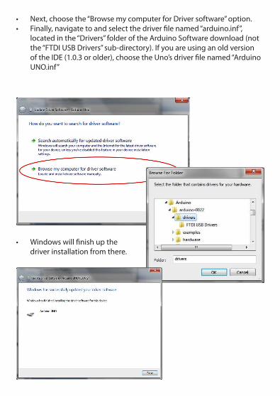
• Next,choosethe“BrowsemycomputerforDriversoftware”option.• Finally,navigatetoandselectthedriverfilenamed“arduino.inf”,
locatedinthe“Drivers”folderoftheArduinoSoftwaredownload(notthe“FTDIUSBDrivers”sub-directory).IfyouareusinganoldversionoftheIDE(1.0.3orolder),choosetheUno’sdriverfilenamed“ArduinoUNO.inf”
• Windowswillfinishupthedriverinstallationfromthere.
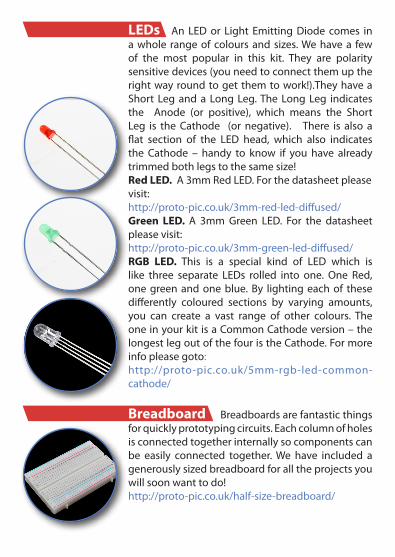
LEDs AnLEDor Light EmittingDiode comes inawhole rangeofcoloursandsizes.Wehavea fewof the most popular in this kit. They are polaritysensitivedevices(youneedtoconnectthemuptherightwayroundtogetthemtowork!).TheyhaveaShort Leganda LongLeg.TheLongLeg indicatesthe Anode (or positive), which means the ShortLeg is theCathode (or negative). There is also aflat section of the LED head, which also indicatesthe Cathode – handy to know if you have alreadytrimmedbothlegstothesamesize!Red LED. A3mmRedLED.Forthedatasheetpleasevisit:http://proto-pic.co.uk/3mm-red-led-diffused/Green LED. A 3mmGreen LED. For the datasheetpleasevisit:http://proto-pic.co.uk/3mm-green-led-diffused/RGB LED. This is a special kind of LED which islike three separate LEDs rolled into one. One Red,onegreenandoneblue.By lightingeachof thesedifferently coloured sections by varying amounts,you can create a vast range of other colours. TheoneinyourkitisaCommonCathodeversion–thelongestlegoutofthefouristheCathode.Formoreinfopleasegoto:http://proto-pic.co.uk/5mm-rgb-led-common-cathode/
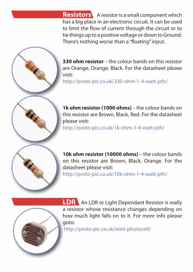
Breadboard Breadboardsarefantasticthingsforquicklyprototypingcircuits.Eachcolumnofholesisconnectedtogetherinternallysocomponentscanbe easily connected together.We have included agenerouslysizedbreadboardforalltheprojectsyouwillsoonwanttodo!http://proto-pic.co.uk/half-size-breadboard/
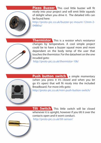
Resistors Aresistorisasmallcomponentwhichhasabigplaceinanelectroniccircuit.ItcanbeusedtolimittheflowofcurrentthroughthecircuitortotiethingsuptoapositivevoltageordowntoGround.There’snothingworsethana“floating”input.
330 ohm resistor–thecolourbandsonthisresistorareOrange,Orange,Black.Forthedatasheetpleasevisit:http://proto-pic.co.uk/330-ohm-1-4-watt-pth/
1k ohm resistor (1000 ohms) –thecolourbandsonthisresistorareBrown,Black,Red.Forthedatasheetpleasevisit:http://proto-pic.co.uk/1k-ohm-1-4-watt-pth/
10k ohm resistor (10000 ohms) –thecolourbandson this resistor are Brown, Black, Orange. For thedatasheetpleasevisit:http://proto-pic.co.uk/10k-ohm-1-4-watt-pth/
LDR AnLDRorLightDependantResistorisreallya resistorwhose resistancechangesdependingonhowmuch light fallson to it. Formore infopleasegoto:http://proto-pic.co.uk/mini-photocell/
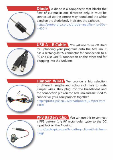
Piezo Buzzer This cool little buzzer will fitnicely into yourproject andwill emit little squealsofdelightwhenyoudrive it. Thedetailed infocanbefoundhere:http://proto-pic.co.uk/buzzer-pc-mount-12mm-2-048khz/
Thermistor This is a resistor who’s resistancechanges by temperature. A cool simple projectcould be to have a buzzer squealmore andmoredependant on the body temp of the user thattouchesthethermistor.Forthedatasheetontheoneincudedgoto:http://proto-pic.co.uk/thermistor-10k/
Push button switch a simple momentary(when you press it it’s closed and when you letgo it’s open) that will fit nicely into the includedBreadboard.Formoreinfogoto:http://proto-pic.co.uk/mini-push-button-switch/
Tilt Switch This little switch will be closedwheneveritisupright,howeverifyoutiltitoverthecontactsopenanditwontconduct.http://proto-pic.co.uk/tilt-sensor/

Slide Switch This switch has three contacts,soyoucanwireituptotriggertwodifferentthings.Also known as a SPDT switch (Single Pole DoubleThrow),moreinfocanbefoundhere:http://proto-pic.co.uk/spdt-mini-power-switch/
Capacitors Acapacitorisacomponentwhichstores energy. It canbe chargedupover timeandthen discharged. Commonly used in electroniccircuitsforanythingfromtimingtoblockingDC.
10nF Capacitor. This Ceramic Capacitor is markedwith‘103’ Itdoesnotmatterwhichway roundyouconnectitup.http://proto-pic.co.uk/ceramic-capacitor-10nf-50v/
100nFCapacitor.Alsoknownas0.1uF,ThisCeramicCapacitor is marked with ‘104’ It does not matterwhichwayroundyouconnectitup.http://proto-pic.co.uk/capacitor-ceramic-0-1uf/
100uFElectrolyticCapacitor.This capacitorhas thenegativeleadmarkedwitharowofminussymbols.Itdefinitelymatterswhichwayroundyouconnectit!http://proto-pic.co.uk/electrolytic-capacitor-100uf-50v/
Diode Adiode is a component thatblocks theflow of current in one direction only. It must beconnectedupthecorrectwayroundandthewhitebandonthediodebodyindicatesthecathode.http://proto-pic.co.uk/diode-rectifier-1a-50v-in4001/
USB A – B Cable Youwillusethisalot!Usedfor uploading your programs onto the Arduino, Ithasa rectangular‘A’ connector for connection toaPCandasquare‘B’connectionontheotherendforpluggingintotheArduino.
Jumper Wires We provide a big selectionof different lengths and colours of male to malejumper wires. They plug into the breadboard andtheconnectionpinsontheArduinoandareusedtoconnectallyourcoolprojectstogether.http://proto-pic.co.uk/breadboard-jumper-wire-pack/
PP3 Battery Clip Youcanusethistoconnecta PP3 battery (the 9V rectangular type) to the DCinputJackontheArduino.http://proto-pic.co.uk/9v-battery-clip-with-2-1mm-plug/
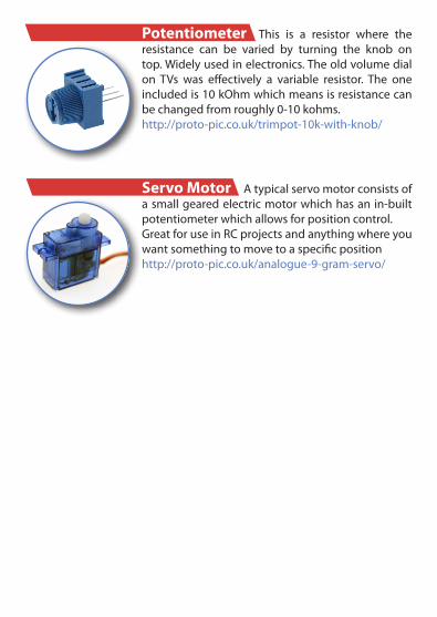
Potentiometer This is a resistor where theresistance can be varied by turning the knob ontop.Widelyusedinelectronics.Theoldvolumedialon TVs was effectively a variable resistor. The oneincludedis10kOhmwhichmeansisresistancecanbechangedfromroughly0-10kohms.http://proto-pic.co.uk/trimpot-10k-with-knob/
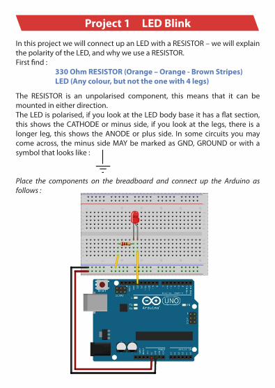
Servo Motor Atypicalservomotorconsistsofasmallgearedelectricmotorwhichhasanin-builtpotentiometerwhichallowsforpositioncontrol.GreatforuseinRCprojectsandanythingwhereyouwantsomethingtomovetoaspecificpositionhttp://proto-pic.co.uk/analogue-9-gram-servo/
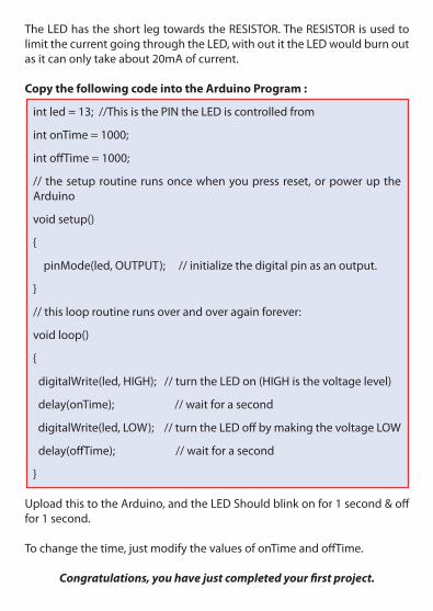
Project 1 LED Blink InthisprojectwewillconnectupanLEDwithaRESISTOR–wewillexplainthepolarityoftheLED,andwhyweuseaRESISTOR.Firstfind:
330 Ohm RESISTOR (Orange – Orange - Brown Stripes)LED (Any colour, but not the one with 4 legs)
The RESISTOR is an unpolarised component, this means that it can bemountedineitherdirection.TheLEDispolarised,ifyoulookattheLEDbodybaseithasaflatsection,this shows theCATHODEorminusside, ifyou lookat the legs, there isalonger leg, this shows theANODEorplus side. In somecircuits youmaycomeacross, theminussideMAYbemarkedasGND,GROUNDorwithasymbolthatlookslike:
Place the components on the breadboard and connect up the Arduino as follows :
TheLEDhastheshortlegtowardstheRESISTOR.TheRESISTORisusedtolimitthecurrentgoingthroughtheLED,withoutittheLEDwouldburnoutasitcanonlytakeabout20mAofcurrent.
Copy the following code into the Arduino Program :
intled=13;//ThisisthePINtheLEDiscontrolledfrom
intonTime=1000;
intoffTime=1000;
// thesetuproutinerunsoncewhenyoupressreset,orpoweruptheArduino
voidsetup()
{
pinMode(led,OUTPUT);//initializethedigitalpinasanoutput.
}
//thislooproutinerunsoverandoveragainforever:
voidloop()
{
digitalWrite(led,HIGH);//turntheLEDon(HIGHisthevoltagelevel)
delay(onTime);//waitforasecond
digitalWrite(led,LOW);//turntheLEDoffbymakingthevoltageLOW
delay(offTime);//waitforasecond
}
UploadthistotheArduino,andtheLEDShouldblinkonfor1second&offfor1second.
Tochangethetime,justmodifythevaluesofonTimeandoffTime.
Congratulations, you have just completed your first project.
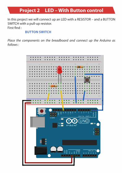
Project 2 LED – With Button control InthisprojectwewillconnectupanLEDwithaRESISTOR–andaBUTTONSWITCHwithapull-upresistor.Firstfind:
BUTTON SWITCH
Place the components on the breadboard and connect up the Arduino as follows :
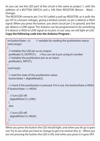
AsyoucanseetheLEDpartofthecircuitisthesameasproject1,withtheadditionof aBUTTONSWITCHanda 10KOhmRESISTOR (Brown–Black –Orange).TheRESISTORconnectspin2to5V(calledapull-upRESISTOR,asitpullsthepinUPtoaknownvoltage),givingalimitedcurrent,sopin2detectsaHIGHsignal.Whenyoupressthebutton,youshortcircuitpin2toground,andthepindetectsaLOWsignal.TheArduinocanbeprogrammedtodosomethingifitdetectsaHIGHorLOWsignalonitspins.Inourcase,wewilllightanLED.Copy the following code into the Arduino Program :
intbuttonState=0;//variableforreadingthepushbuttonstatusvoidsetup(){//initializetheLEDpinasanoutput:pinMode(13,OUTPUT);//Youcansetitjustusingitsnumber//initializethepushbuttonpinasaninput:pinMode(2,INPUT);}voidloop(){//readthestateofthepushbuttonvalue:buttonState=digitalRead(2);
//checkifthepushbuttonispressed.ifitisnot,thebuttonStateisHIGH:if(buttonState==HIGH){ //turnLEDoff:digitalWrite(13,LOW); } else {//turnLEDoff:digitalWrite(13,HIGH); }}
WhenyoupressthebuttontheLEDshouldlight,andwhenyouletgoitgoesout.Trytoseewhatyouhavetochangetogetittoreversethis,ie–WhenyouarenotpressingthebuttontheLEDisON,andwhenyoupressititgoesOFF.
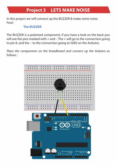
Project 3 LETS MAKE NOISE InthisprojectwewillconnectuptheBUZZER&makesomenoise.Find:
The BUZZER
TheBUZZERisapolarisedcomponent,ifyouhavealookonthebackyouwillseethepinsmarkedwith+and-.The+willgototheconnectiongoingtopin8,andthe–totheconnectiongoingtoGNDontheArduino.
Place the components on the breadboard and connect up the Arduino as follows :
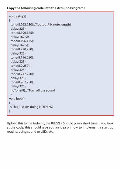
Copy the following code into the Arduino Program :
voidsetup(){tone(8,262,250);//(outputPIN,note,length)delay(325);tone(8,196,125);delay(162.5);tone(8,196,125);delay(162.5);tone(8,220,250);delay(325);tone(8,196,250);delay(325);tone(8,0,250);delay(325);tone(8,247,250);delay(325);tone(8,262,250);delay(325);noTone(8);//Turnoffthesound }voidloop(){//ThisjustsitsdoingNOTHING}
UploadthistotheArduino,theBUZZERShouldplayashorttune.Ifyoulookatthecode,thisshouldgiveyouanideaonhowtoimplementastartuproutine,usingsoundorLEDsetc.
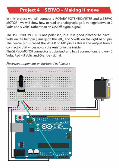
Project 4 SERVO – Making it move In this projectwewill connect a ROTARY POTENTIOMETER and a SERVOMOTOR–wewillshowhowtoreadananalogvoltage(avoltagebetween0Voltsand5Volts)ratherthananOn/Offdigitalsignal.
The POTENTIOMETER is not polarised, but it is good practice to have 0Voltsonthefirstpin(usuallyontheleft),and5Voltsontherighthandpin.Thecentrepin iscalledtheWIPERorTAPpinas this is theoutput fromaconnectorthatwipesacrosstheresistorintheinside.TheSERVOMOTORconnectorispolarised,andhas3connections:Brown–0Volts,Red–5VoltsandOrange-signal.
Place the components on the board as follows :
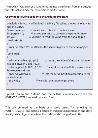
ThePOTENTIOMETERyouhaveinthekitmaybedifferentfromthisone,buttheinternalandexternalconnectionsarethesame.
Copy the following code into the Arduino Program :
#include<Servo.h>//ThisloadsaLibraryfiletellingtheArduinohowtousetheSERVOServomyservo;//createservoobjecttocontrolaservointpotpin=0;//analogpinusedtoconnectthepotentiometerintval;//variabletoreadthevaluefromtheanalogpinvoidsetup(){ myservo.attach(9);//attachestheservoonpin9totheservoobject} voidloop(){ val=analogRead(potpin);//readsthevalueofthepotentiometer(valuebetween0and1023)val=map(val,0,1023,0,179);//scaleittouseitwiththeservo(valuebetween0and179)myservo.write(val);//setstheservopositionaccordingtothescaledvaluedelay(15);//waitsfortheservotogetthere}
Upload this to the Arduino and the SERVO should move when thePOTENTIOMETERisrotatedbackandforth.
This can be used as the basis of a servo tester. Try removing thePOTENTIOMETERandaddingacoupleofbuttonstomakeitopenandclose.Seeifyoucanfigureoutwherethecodeneedschangedtodothis.
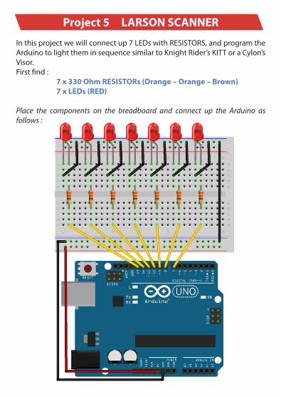
Project 5 LARSON SCANNER Inthisprojectwewillconnectup7LEDswithRESISTORS,andprogramtheArduinotolighttheminsequencesimilartoKnightRider’sKITToraCylon’sVisor.Firstfind:
7 x 330 Ohm RESISTORs (Orange – Orange – Brown)7 x LEDs (RED)
Place the components on the breadboard and connect up the Arduino as follows :
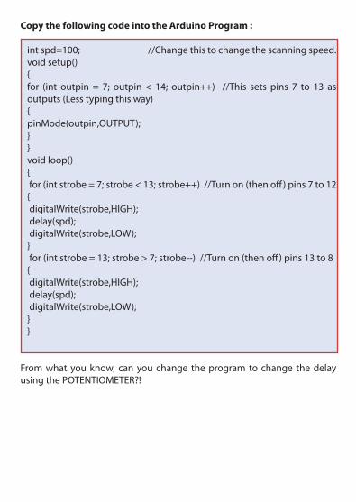
Copy the following code into the Arduino Program :
intspd=100;//Changethistochangethescanningspeed.voidsetup(){for (int outpin = 7; outpin < 14; outpin++) //This sets pins 7 to 13 asoutputs(Lesstypingthisway){ pinMode(outpin,OUTPUT);} }voidloop(){for(intstrobe=7;strobe<13;strobe++)//Turnon(thenoff)pins7to12{digitalWrite(strobe,HIGH);delay(spd);digitalWrite(strobe,LOW);}for(intstrobe=13;strobe>7;strobe--)//Turnon(thenoff)pins13to8{digitalWrite(strobe,HIGH);delay(spd);digitalWrite(strobe,LOW);}}
Fromwhatyouknow, canyouchange theprogram tochange thedelayusingthePOTENTIOMETER?!

www.proto-pic.co.uk
TechnicalSupport+44(0)1592572092
Formoreexamplesandfurtherinformationonthiskitplease see our online documentation at
learn.proto-pic.co.uk
Proto-PIC