Embed Size (px)
Citation preview
P/N 116087REV. 9/97
E-72
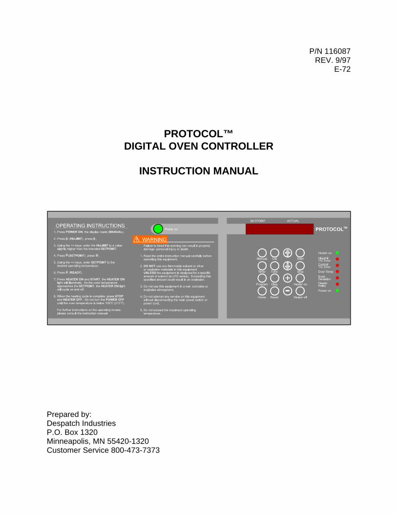
PROTOCOL™DIGITAL OVEN CONTROLLER
INSTRUCTION MANUAL
Prepared by:Despatch IndustriesP.O. Box 1320Minneapolis, MN 55420-1320Customer Service 800-473-7373

Notice
Users of this equipment must comply with operating procedures and training ofoperation personnel as required by the Occupational Safety and Health Act (OSHA)of 1970, Section 6 and relevant safety standards, as well as other safety rules andregulations of state and local governments. Refer to the relevant safety standardsin OSHA and National Fire Protection Association (NFPA), section 86 of 1990.
Caution
Setup and maintenance of the equipment should be performed by qualifiedpersonnel who are experienced in handling all facets of this type of system. Improper setup and operation of this equipment could cause an explosion that mayresult in equipment damage, personal injury or possible death.
Thank you for choosing Despatch Industries. We appreciatethe opportunity to work with you and to meet your heatprocessing needs. We believe that you have selected thefinest equipment available in the heat processing industry.
At Despatch, our service does not end after the purchaseand delivery of our equipment. For this reason we havecreated the Service Products Division within Despatch. TheService Products Division features our Response Center forcustomer service. The Response Center will direct andtrack your service call to ensure satisfaction.
Whenever you need service or replacement parts, contactthe Response Center at 1-800-473-7373: FAX 612-781-5353.
Thank you for choosing Despatch.
Sincerely,
Despatch Industries
Despatch Product Warranty
Parts, Materials and Labor
Despatch warrants all parts and materials to be free from defects in material and workmanship for a period of one (1) year from thedate of shipment unless otherwise mutually agreed upon in writing, or 2,000 hours of operation, whichever occurs first. (Note:Laboratory oven electric heaters are warranted for a period of five [5] years from date of shipment.)
Despatch will repair or replace, at Despatch’s option, FOB Despatch’s factory, parts and materials covered by this warranty.Despatch is not responsible for parts or material failures resulting from misuse, abuse, inadequate preventive maintenance, actsof nature, or non-conforming utilities, including electrical, fuel supply, environmental and intake/exhaust provisions. This warrantyalso does not cover normal wear or routine maintenance parts and materials expressly designed as expendable/consumable andreplaceable.
Labor services for parts and materials replacement and repair to support this warranty are available at Despatch’s normal servicefees. This service is provided worldwide by a network of factory trained professionals.
Terms and Conditions
The foregoing warranty shall be deemed valid and binding upon Despatch if and only if the Customer:1. Installs, loads, operates and maintains the equipment supplied hereunder in accordance with the instruction manual
provided upon delivery and product labeling affixed to the subject equipment.2. Agrees to follow the Emergency Procedure spelled out below.
Exclusions/Limitations of Liability
This warranty DOES NOT cover expenses incurred in the process of diagnosing and/or repairing equipment resulting from:a) operator error, b) attempted service or modifications by other than Despatch authorized technicians, c) any use of the equipmentwhich is inconsistent with the operation manual or labeling, d) inadequate preventive maintenance, or e) acts of nature, such asfloods, fire, earthquake, or acts of war or civil emergency.
Despatch shall not, in any event, be liable for indirect, special, consequential or liquidated damages or penalties, including loss ofrevenue, profits or business opportunities resulting from interruption of process or production. Despatch shall further be heldblameless for any damages or expenses resulting from delays in our attempts to diagnose and repair the equipment, unavailabilityof spare parts or inaccessibility of the equipment. Specifically excluded from this warranty is responsibility for internal and externalcorrosion damages to the equipment.
Non-Compliance
Despatch reserves the right to suspend and withhold service as provided under this warranty in the event of non-compliance bythe Customer to any terms and conditions of this warranty. Further, Despatch is held harmless for any loss of production, incurredexpenses, and other inconveniences due to suspension of service under this non-compliance provision.
Emergency Procedure
In an emergency situation, Customer agrees to: a) immediately shut off fuel or energy supply (gas and electricity), b) call 911 foremergency assistance if needed, and c) call Despatch Service.
THE FOREGOING WARRANTY IS EXCLUSIVE AND IN LIEU OF ALL OTHER EXPRESS AND IMPLIED WARRANTIESWHATSOEVER, AND SPECIFICALLY THERE ARE NOT IMPLIED WARRANTIES OF MERCHANTABILITY OR OF FITNESS FORA PARTICULAR PURPOSE.
THE FOREGOING WARRANTY IS NOT TRANSFERABLE IN SITUATIONS WHERE EQUIPMENT OWNERSHIP ISTRANSFERRED TO ANOTHER PARTY.
Despatch ServiceWorldwide Phone 612-781-5363; Worldwide Fax 612-781-5185; North American Phone 800-473-7373
Please see reverse side for other service offerings BB5 (5/97)
DespatchService Support Programs
Despatch continues to deliver exceptional products backed by a strong sense of responsibility and drive for long term customersatisfaction. Your partnership with Despatch can offer even higher value through your subscription to one of Despatch’s high valueservice programs.
Warranty
Despatch’s exclusive, comprehensive service programs start with the warranty which is described on the other side of thisdocument. This warranty can be expanded immediately to meet your most stringent service needs. Despatch Service will be ableto answer your service questions and provide a quotation for the immediate expansion of your product warranty.
Immediate Service Response
The key to an effective service program is response. Wherever your location, Despatch is only a phone call away. Our NorthAmerican customers can reach Despatch at 1-800-473-7373. Worldwide customers can call 1-612-781-5363 or FAX1-612-781-5485. Our Customer Service Technicians have over 200 years combined experience and access to detailed design andmanufacturing documentation specific to your Despatch unit(s). This exacting level of service is a benefit only Despatch can provideand means that you can expect speedy, accurate and the most cost effective response.
Field Service Network
A worldwide network of factory trained Service Professionals is available to support your Despatch equipment. From routine repairto certified instrument calibration, the Despatch service network is positioned to respond to your needs. As a manufacturer of customequipment, our service programs are customized to meet your specific needs regarding:
1. Service scope2. Response time3. Preventive maintenance frequency and content4. Payment method
Sustained Service Support
At Despatch, long term customer satisfaction means more than just responding quickly and effectively to our customers’ serviceneeds. It means offering comprehensive customer support well beyond the scope and duration of our initial warranty. Despatchoffers two basic service packages which are customized to each individual customer’s need. These service packages are titled FullService and Preventive Maintenance Plus+ service agreement products. Each is unique in the industry and offer the followingbenefits:
1. Priority response for minimum production interruption2. Preventive maintenance for longer product life3. Discounts on parts and services4. Various payment plans to ease budgeting and recording expenses5. Reduce purchase ordering costs
Despatch ServiceWorldwide Phone 612-781-5363; Worldwide Fax 612-781-5185; North American Phone 800-473-7373

i
TABLE OF CONTENTS
INTRODUCTION . . . . . . . . . . . . . . . . . . . . . . . . . . . . . . . . . . . . . . . . . . . . . . . . . . . . . 1
THEORY OF OPERATION . . . . . . . . . . . . . . . . . . . . . . . . . . . . . . . . . . . . . . . . . . . . . . 2Protocol . . . . . . . . . . . . . . . . . . . . . . . . . . . . . . . . . . . . . . . . . . . . . . . . . . . . . . . 2Keypad Controls . . . . . . . . . . . . . . . . . . . . . . . . . . . . . . . . . . . . . . . . . . . . . . . . 3Status Indicator LEDs . . . . . . . . . . . . . . . . . . . . . . . . . . . . . . . . . . . . . . . . . . . . 4Operating Modes . . . . . . . . . . . . . . . . . . . . . . . . . . . . . . . . . . . . . . . . . . . . . . . . 5
Manual Mode . . . . . . . . . . . . . . . . . . . . . . . . . . . . . . . . . . . . . . . . . . . . . 5Timer Mode . . . . . . . . . . . . . . . . . . . . . . . . . . . . . . . . . . . . . . . . . . . . . . . 5Program Mode . . . . . . . . . . . . . . . . . . . . . . . . . . . . . . . . . . . . . . . . . . . . 5
Calibration Zero Offset . . . . . . . . . . . . . . . . . . . . . . . . . . . . . . . . . . . . . . . . . . . . 6Tune Setting . . . . . . . . . . . . . . . . . . . . . . . . . . . . . . . . . . . . . . . . . . . . . . . . . . . 7Protocol Hi-Limit . . . . . . . . . . . . . . . . . . . . . . . . . . . . . . . . . . . . . . . . . . . . . . . . . 8
INSTRUCTIONS . . . . . . . . . . . . . . . . . . . . . . . . . . . . . . . . . . . . . . . . . . . . . . . . . . . . . . 9Start-Up . . . . . . . . . . . . . . . . . . . . . . . . . . . . . . . . . . . . . . . . . . . . . . . . . . . . . . . 9Manual Mode . . . . . . . . . . . . . . . . . . . . . . . . . . . . . . . . . . . . . . . . . . . . . . . . . . 10
Startup . . . . . . . . . . . . . . . . . . . . . . . . . . . . . . . . . . . . . . . . . . . . . . . . . . 10Run . . . . . . . . . . . . . . . . . . . . . . . . . . . . . . . . . . . . . . . . . . . . . . . . . . . . 10Stop . . . . . . . . . . . . . . . . . . . . . . . . . . . . . . . . . . . . . . . . . . . . . . . . . . . . 11
Timer Mode . . . . . . . . . . . . . . . . . . . . . . . . . . . . . . . . . . . . . . . . . . . . . . . . . . . 12Startup . . . . . . . . . . . . . . . . . . . . . . . . . . . . . . . . . . . . . . . . . . . . . . . . . 12Run . . . . . . . . . . . . . . . . . . . . . . . . . . . . . . . . . . . . . . . . . . . . . . . . . . . . 13Manually Stop . . . . . . . . . . . . . . . . . . . . . . . . . . . . . . . . . . . . . . . . . . . . 13
Program Mode . . . . . . . . . . . . . . . . . . . . . . . . . . . . . . . . . . . . . . . . . . . . . . . . . 15Startup . . . . . . . . . . . . . . . . . . . . . . . . . . . . . . . . . . . . . . . . . . . . . . . . . . 15Run . . . . . . . . . . . . . . . . . . . . . . . . . . . . . . . . . . . . . . . . . . . . . . . . . . . . 18Manually Stop . . . . . . . . . . . . . . . . . . . . . . . . . . . . . . . . . . . . . . . . . . . . 18
ii
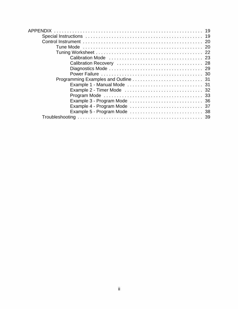
APPENDIX . . . . . . . . . . . . . . . . . . . . . . . . . . . . . . . . . . . . . . . . . . . . . . . . . . . . . . . . . 19Special Instructions . . . . . . . . . . . . . . . . . . . . . . . . . . . . . . . . . . . . . . . . . . . . . 19Control Instrument . . . . . . . . . . . . . . . . . . . . . . . . . . . . . . . . . . . . . . . . . . . . . . 20
Tune Mode . . . . . . . . . . . . . . . . . . . . . . . . . . . . . . . . . . . . . . . . . . . . . . 20Tuning Worksheet . . . . . . . . . . . . . . . . . . . . . . . . . . . . . . . . . . . . . . . . . 22
Calibration Mode . . . . . . . . . . . . . . . . . . . . . . . . . . . . . . . . . . . . 23Calibration Recovery . . . . . . . . . . . . . . . . . . . . . . . . . . . . . . . . . 28Diagnostics Mode . . . . . . . . . . . . . . . . . . . . . . . . . . . . . . . . . . . . 29Power Failure . . . . . . . . . . . . . . . . . . . . . . . . . . . . . . . . . . . . . . . 30
Programming Examples and Outline . . . . . . . . . . . . . . . . . . . . . . . . . . . 31Example 1 - Manual Mode . . . . . . . . . . . . . . . . . . . . . . . . . . . . . 31Example 2 - Timer Mode . . . . . . . . . . . . . . . . . . . . . . . . . . . . . . 32Program Mode . . . . . . . . . . . . . . . . . . . . . . . . . . . . . . . . . . . . . . 33Example 3 - Program Mode . . . . . . . . . . . . . . . . . . . . . . . . . . . . 36Example 4 - Program Mode . . . . . . . . . . . . . . . . . . . . . . . . . . . . 37Example 5 - Program Mode . . . . . . . . . . . . . . . . . . . . . . . . . . . . 38
Troubleshooting . . . . . . . . . . . . . . . . . . . . . . . . . . . . . . . . . . . . . . . . . . . . . . . . 39
1
INTRODUCTIONThe special features of the Protocol™ include:
C PID Tuning
C Programmable up to 48 segments
C Built-in manual reset hi-limit control
C Built-in process timer
C Self-diagnostics
C Digital display
C Three (3) event outputs
C RS422/RS485 bi-directional communications capability
C Recursive profile capability

2
Figure 2. Main Display and Keypad on Protocol Control
THEORY OF OPERATIONThis section describes the Protocol installed in the LAC, LAD, LFD and LND Seriesovens.
ProtocolThe ovens are equipped with a modular microprocessor based digital temperaturecontroller.
The Despatch Protocol temperature controller is a dual functioning controller/high limitinstrument. The control portion of Protocol incorporates a microprocessor to digitallycontrol process variables with minimal temperature fluctuations.
The high limit portion of Protocol protects the product and/or the oven itself. If theproduct being processed has a critical high temperature limit, the Hi-Limit parametershould be set to a temperature somewhat below the temperature at which the productcould be damaged. If the product does not have a critical high temperature limit, the Hi-Limit parameter should be set to a value slightly higher than the highest programmedsetpoint to protect the oven equipment.
3
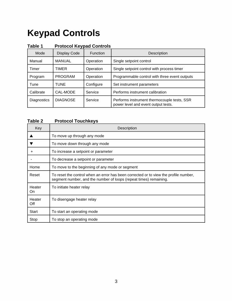
Keypad ControlsTable 1 Protocol Keypad Controls
Mode Display Code Function Description
Manual MANUAL Operation Single setpoint control
Timer TIMER Operation Single setpoint control with process timer
Program PROGRAM Operation Programmable control with three event outputs
Tune TUNE Configure Set instrument parameters
Calibrate CAL-MODE Service Performs instrument calibration
Diagnostics DIAGNOSE Service Performs instrument thermocouple tests, SSRpower level and event output tests.
Table 2 Protocol Touchkeys
Key Description
• To move up through any mode
– To move down through any mode
+ To increase a setpoint or parameter
- To decrease a setpoint or parameter
Home To move to the beginning of any mode or segment
Reset To reset the control when an error has been corrected or to view the profile number,segment number, and the number of loops (repeat times) remaining.
HeaterOn
To initiate heater relay
HeaterOff
To disengage heater relay
Start To start an operating mode
Stop To stop an operating mode

4
Status Indicator LEDsProtocol has seven indicator LEDs that provide the following relevant information to theuser.
Table 3 Protocol Indicator LEDs
LED Function
Power on Lights when the power on pushbutton is pressed.
Heater relay Lights when a mode is ready for operation and the heater on key is pressed.
Soak Deviation Lights when the process temperature is not held within the user-specified soakdeviation limits. The light turns off when the temperature is within the soakdeviation limit.
Over Temp Lights when the process temperature exceeds the high limit value. The overtemperature light remains lit until the Reset is pressed.
Control T/C Error Lights when Lights when Protocol receives a control thermocouple error. theReset key clears the error upon corrective action.
Hi-Limit T/CError
Lights when Protocol receives a hi-limit thermocouple error. The Reset keyclears the error upon corrective action.
The Despatch Protocol temperature controller has been designed for ease of use whilemaintaining elaborate and versatile control capabilities.
5
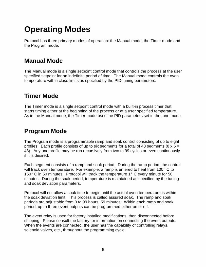
Operating ModesProtocol has three primary modes of operation: the Manual mode, the Timer mode andthe Program mode.
Manual Mode
The Manual mode is a single setpoint control mode that controls the process at the userspecified setpoint for an indefinite period of time. The Manual mode controls the oventemperature within close limits as specified by the PID tuning parameters.
Timer Mode
The Timer mode is a single setpoint control mode with a built-in process timer thatstarts timing either at the beginning of the process or at a user specified temperature. As in the Manual mode, the Timer mode uses the PID parameters set in the tune mode.
Program Mode
The Program mode is a programmable ramp and soak control consisting of up to eightprofiles. Each profile consists of up to six segments for a total of 48 segments (8 x 6 =48). Any one profile may be run recursively from two to 99 cycles or even continuouslyif it is desired.
Each segment consists of a ramp and soak period. During the ramp period, the controlwill track oven temperature. For example, a ramp is entered to heat from 100E C to150E C in 50 minutes. Protocol will track the temperature 1E C every minute for 50minutes. During the soak period, temperature is maintained as specified by the tuningand soak deviation parameters.
Protocol will not allow a soak time to begin until the actual oven temperature is withinthe soak deviation limit. This process is called assured soak. The ramp and soakperiods are adjustable from 0 to 99 hours, 59 minutes. Within each ramp and soakperiod, up to three event outputs can be programmed either on or off.
The event relay is used for factory installed modifications, then disconnected beforeshipping. Please consult the factory for information on connecting the event outputs. When the events are connected, the user has the capability of controlling relays,solenoid valves, etc., throughout the programming cycle.
6
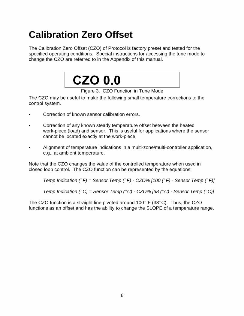
Figure 3. CZO Function in Tune Mode
Calibration Zero OffsetThe Calibration Zero Offset (CZO) of Protocol is factory preset and tested for thespecified operating conditions. Special instructions for accessing the tune mode tochange the CZO are referred to in the Appendix of this manual.
The CZO may be useful to make the following small temperature corrections to thecontrol system.
C Correction of known sensor calibration errors.
C Correction of any known steady temperature offset between the heatedwork-piece (load) and sensor. This is useful for applications where the sensorcannot be located exactly at the work-piece.
C Alignment of temperature indications in a multi-zone/multi-controller application,e.g., at ambient temperature.
Note that the CZO changes the value of the controlled temperature when used inclosed loop control. The CZO function can be represented by the equations:
Temp Indication (EF) = Sensor Temp (EF) - CZO% [100 (EF) - Sensor Temp (EF)]
Temp Indication (EC) = Sensor Temp (EC) - CZO% [38 (EC) - Sensor Temp (EC)]
The CZO function is a straight line pivoted around 100E F (38EC). Thus, the CZOfunctions as an offset and has the ability to change the SLOPE of a temperature range.
7
NOTE: The CZO function iseasily set for specific operatingconditions.
NOTE: Reset times greater than 35seconds/repeat are not recommended.
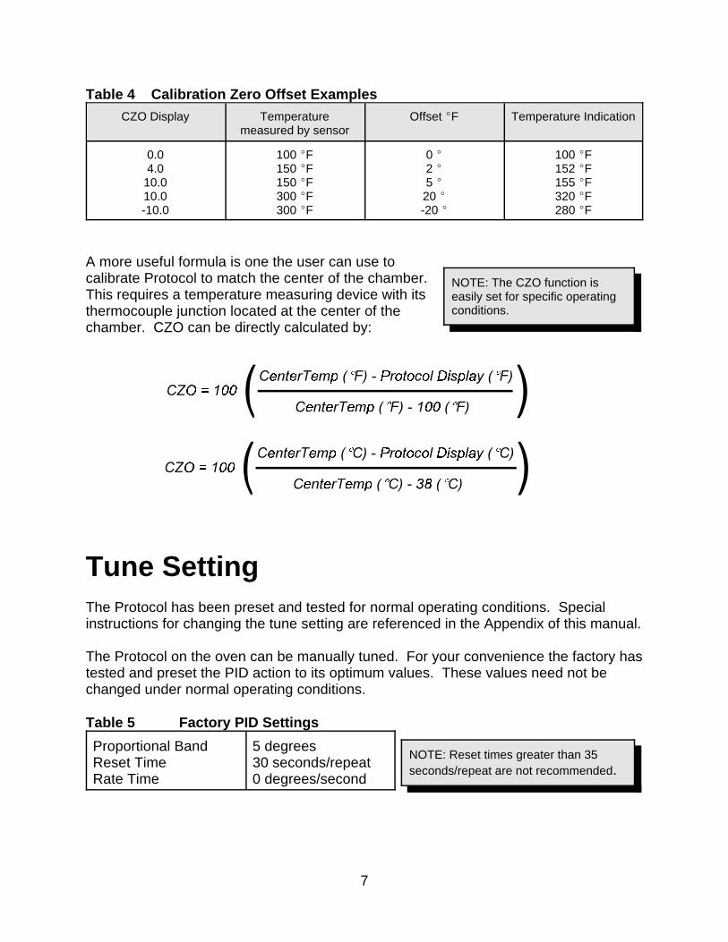
Table 4 Calibration Zero Offset Examples
CZO Display Temperaturemeasured by sensor
Offset EF Temperature Indication
0.04.0
10.010.0-10.0
100 EF150 EF150 EF300 EF300 EF
0 E2 E5 E20 E-20 E
100 EF152 EF155 EF320 EF280 EF
A more useful formula is one the user can use tocalibrate Protocol to match the center of the chamber. This requires a temperature measuring device with itsthermocouple junction located at the center of thechamber. CZO can be directly calculated by:
Tune SettingThe Protocol has been preset and tested for normal operating conditions. Specialinstructions for changing the tune setting are referenced in the Appendix of this manual.
The Protocol on the oven can be manually tuned. For your convenience the factory hastested and preset the PID action to its optimum values. These values need not bechanged under normal operating conditions.
Table 5 Factory PID Settings
Proportional BandReset TimeRate Time
5 degrees30 seconds/repeat0 degrees/second
8
WARNING: Never operate theoven at a temperature in excessof the maximum operatingtemperature.
Protocol Hi-LimitProtocol will not let the high limit value drop below the setpoint value. In certainsituations, it may be necessary to change the setpoint first and then adjust the high limitvalue.
It will be necessary to reset the hi-limit whenever ithas tripped. The hi-limit may be reset by firstallowing the oven chamber to cool slightly (orincreasing the parameter by several degrees) andpushing the Reset key. During a high limit conditionthe Over Temp LED will turn on thus deactivatingthe heater.
9
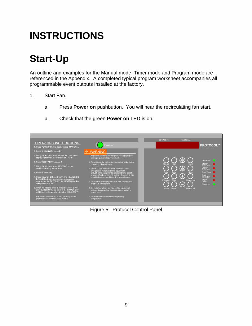
Figure 5. Protocol Control Panel
INSTRUCTIONS
Start-UpAn outline and examples for the Manual mode, Timer mode and Program mode arereferenced in the Appendix. A completed typical program worksheet accompanies allprogrammable event outputs installed at the factory.
1. Start Fan.
a. Press Power on pushbutton. You will hear the recirculating fan start.
b. Check that the green Power on LED is on.
10
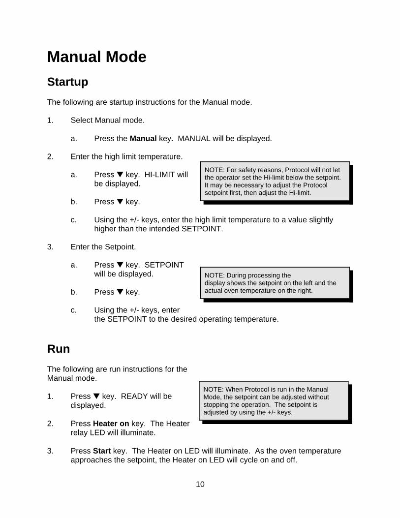
NOTE: For safety reasons, Protocol will not letthe operator set the Hi-limit below the setpoint. It may be necessary to adjust the Protocolsetpoint first, then adjust the Hi-limit.
NOTE: During processing thedisplay shows the setpoint on the left and theactual oven temperature on the right.
NOTE: When Protocol is run in the ManualMode, the setpoint can be adjusted withoutstopping the operation. The setpoint isadjusted by using the +/- keys.
Manual Mode
Startup
The following are startup instructions for the Manual mode.
1. Select Manual mode.
a. Press the Manual key. MANUAL will be displayed.
2. Enter the high limit temperature.
a. Press – key. HI-LIMIT willbe displayed.
b. Press – key.
c. Using the +/- keys, enter the high limit temperature to a value slightlyhigher than the intended SETPOINT.
3. Enter the Setpoint.
a. Press – key. SETPOINTwill be displayed.
b. Press – key.
c. Using the +/- keys, enterthe SETPOINT to the desired operating temperature.
Run
The following are run instructions for theManual mode.
1. Press – key. READY will bedisplayed.
2. Press Heater on key. The Heaterrelay LED will illuminate.
3. Press Start key. The Heater on LED will illuminate. As the oven temperatureapproaches the setpoint, the Heater on LED will cycle on and off.
11
Stop
The following are stop instructions for the Manual mode.
1. Press the Heater off key. The Heater Relay LED will shut off.
2. Wait for oven temperature to fall below 100E C (212E F).
3. When the Manual mode is complete, press the Reset key to display the finalprocess temperatures.
4. Press the Stop key.
5. Press the Power on pushbutton to turn power off.
An example of the Manual mode is referenced in the Appendix.
12
NOTE: During processing thedisplay shows the setpoint on theleft and the actual oven tempera-ture on the right.
NOTE: For safety reasons, Protocolwill not let the operator set the Hi-limit below the setpoint. It may benecessary to adjust the Protocolsetpoint first, then adjust the Hi-limit.
Timer Mode
Startup
The following are startup instructions for the Timermode.
1. Select Timer mode.
a. Press Timer key. TIMER will bedisplayed.
2. Enter the high limit temperature.
a. Press – key. HI-LIMIT will bedisplayed.
b. Press – key.
c. Using the +/- keys, enter the high limit temperature to a value slightlyhigher than the intended setpoint.
3. Enter the Setpoint.
a. Press – key. SETPOINT will be displayed.
b. Press – key.
c. Using the +/- keys, enter the SETPOINT to the desired operatingtemperature.
4. Enter the process time.
a. Press – key. TIME will be displayed.
b. Using the +/- keys, enter the time of the process. (HHMM (hours/minutes)or MMSS (minutes/ seconds) selected in the tune mode).
5. Enter timer starting temperature.
a. Press the – key. TEMP YES/NO will be displayed.
13
NOTE: When the Timer mode isrunning, pressing the Start key willdisplay the time remaining in thecycle. The display will showTRHHMMSS which stands for thetime remaining, hours, minutesand seconds.
b. Use the + or - keys to select either YES or NO.
C Press the - key to display NO and begin timing at ambient.
C Press the + key to display YES and begin timing at the followinginput temperature.
c. Press the – key. TEMP and the begin timing temperature will bedisplayed.
d. If YES was selected in step b, use the + or - keys to enter the temperatureat which the process timer begins timing.
If NO was selected in step b, this setpoint has no bearing on ovenoperation.
Run
The following are run instructions for the Timer mode.
1. Press the – key. READY will be displayed.
2. Press the Heater on key. The Heater RelayLED will illuminate.
3. Press the Start key. The Heater on LED willilluminate and the setpoint and the actualtemperature will be displayed. As the oventemperature approaches the setpoint, theHeater on LED will cycle on and off.
Manually Stop
The following are manual stop instructions for the Timer mode.
1. Press the Heater off key.
2. Wait for oven temperature to fall below 100E C (212E F).
3. When the Timer mode is complete, press the Reset key to display the finalprocess temperatures.
4. Press the Stop key.

14
5. Press the Power on pushbutton to turn power off.
An example of the Timer mode is referenced in the Appendix of this manual.

15
NOTE: All profiles entered can becleared by using the PROF CLRfunction in the TUNE mode.
NOTE: For safety reasons,Protocol will not let the operatorset the Hi-Limit below the setpoint. It may be necessary to adjust theProtocol setpoint first, then adjustthe Hi-Limit.
NOTE: During processing thedisplay shows the setpoint on theleft and the actual oventemperature on the right.
NOTE: If all event relays aredisconnected or no modificationsinvolving event relays have beenmade to your particular oven,programming the events has noeffect on oven operation.
Program Mode
Startup
The following are startup instructions for theProgram mode.
In any one segment, if the ramp and soak times arezero, Protocol ignores the remaining segments of the profile. A soak period will notbegin until the actual oven temperature is within the soak deviation limit. During anysegment of a profile, if the actual oven temperature falls outside of the soak deviationlimit, the Soak Deviation LED will be illuminated.
1. Select Program mode.
a. Press Program key. PROGRAM willbe displayed.
2. Enter the high limit temperature.
a. Press – key. HI-LIMIT will bedisplayed.
b. Press – key.
c. Use the + or - keys to enter the high limit temperature to a value higherthan the intended setpoints.
3. Enter the profile number.
a. Press – key. PROFILES will be displayed.
b. Press – key. PRO - 1 will be displayed.
c. Use the + or - keys to enter the profile number to program.
4. Program the profile.
a. Press – key. SEG - 1 will bedisplayed.
b. Program the ramp rate.
1. Press – key. RAMP0001 willbe displayed.
16
WARNING: Never operate the ovenat a temperature in excess of themaximum operating temperature.
2. Use the + or - keys to enter the ramp time.
c. Program the events desired during the ramp time.
1. Press – key. EVENTS will be displayed.
2. Press – key for each event.
3. Use the + or - keys to program the event outputs ON or OFF for theramp period.
d. Program the ramp ending temperature.
1. Press – key. TEMP and the ramp ending temperature will bedisplayed.
2. Use the + or - keys to enter the desired ramp ending temperature.
e. Program the soak time.
1. Press – key. SOAK and thesoak time will be displayed.
2. Use the + or - keys to enter the soak time.
f. Program the events desired during the soak time.
1. Press – key. EVENTS will be displayed.
2. Press – for each event.
3. Use the + or - keys to program the event ON or OFF for the soakperiod.
g. Enter the remaining segments 2-6 by following steps a through f.
17
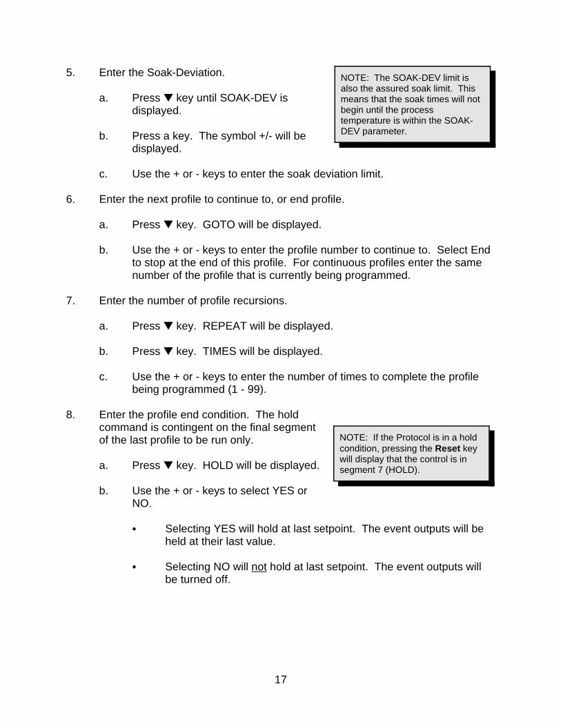
NOTE: The SOAK-DEV limit isalso the assured soak limit. Thismeans that the soak times will notbegin until the processtemperature is within the SOAK-DEV parameter.
NOTE: If the Protocol is in a holdcondition, pressing the Reset keywill display that the control is insegment 7 (HOLD).
5. Enter the Soak-Deviation.
a. Press – key until SOAK-DEV isdisplayed.
b. Press a key. The symbol +/- will bedisplayed.
c. Use the + or - keys to enter the soak deviation limit.
6. Enter the next profile to continue to, or end profile.
a. Press – key. GOTO will be displayed.
b. Use the + or - keys to enter the profile number to continue to. Select Endto stop at the end of this profile. For continuous profiles enter the samenumber of the profile that is currently being programmed.
7. Enter the number of profile recursions.
a. Press – key. REPEAT will be displayed.
b. Press – key. TIMES will be displayed.
c. Use the + or - keys to enter the number of times to complete the profilebeing programmed (1 - 99).
8. Enter the profile end condition. The holdcommand is contingent on the final segmentof the last profile to be run only.
a. Press – key. HOLD will be displayed.
b. Use the + or - keys to select YES orNO.
C Selecting YES will hold at last setpoint. The event outputs will beheld at their last value.
C Selecting NO will not hold at last setpoint. The event outputs willbe turned off.
18
NOTE: When in the Programmode, pressing the Start key willdisplay the time remaining in thecycle (TRHHMMSS). Pressing theReset key will display the profilenumber, segment number and theloops (REPEAT TIMES)remaining.
Run
The following are run instructions for the Programmode.
1. Press Home key until PROGRAM isdisplayed.
2. Press – key until PRO-1 is displayed.
3. Make sure the correct starting profile is entered by pressing + or -.
4. Press the • key until READY is displayed.
5. Press Heater on key. The Heater relay LED will illuminate.
6. Press Start key. The Heater on LED will illuminate. As the oven temperatureapproaches the setpoint, the Heater on LED will cycle on and off. Duringprocessing, the display shows the setpoint on the left and the actual oventemperature on the right.
Manually Stop
The following are manual stop instructions for the Program mode.
1. Press Heater off key.
2. Wait for oven temperature to fall below 100EC (212EF).
3. Press the Reset key to display the final process temperature.
4. Press Stop key.
5. Press Power on pushbutton to turn power off.
Examples of the Program mode are referenced in the Appendix of this manual.

19
APPENDIX
Special InstructionsThe Protocol has been preset and tested at the factory for normal operating conditions. In most applications, it will not be necessary to alter the oven's settings. This sectioncontains additional information and reference for special operating conditions.
20
Control Instrument
Tune Mode
Various functions of the control instrument are set by parameters in the tune mode. Toaccess the tune mode, it is necessary to enter the proper code.
1. Press Tune key. The display reads TUNE.
2. Press – key. CODE *** will be displayed.
3. Enter +, -, -, +, -, +. PID TUNE will be displayed.
The PID tuning parameters may be entered. The units are listed below.
P = degreesI = seconds/repeatD = degrees/second
21
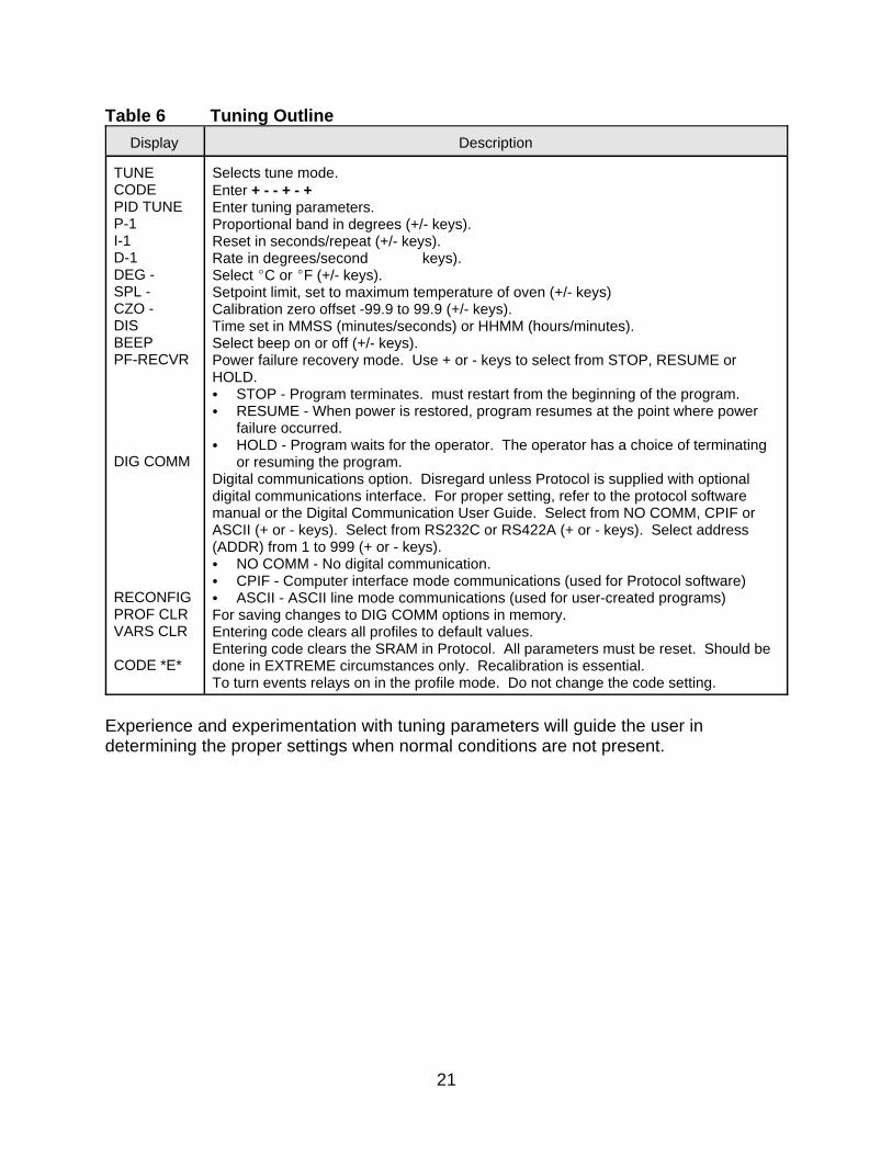
Table 6 Tuning Outline
Display Description
TUNECODEPID TUNEP-1I-1D-1DEG -SPL -CZO -DISBEEPPF-RECVR
DIG COMM
RECONFIGPROF CLRVARS CLR
CODE *E*
Selects tune mode.Enter + - - + - +Enter tuning parameters.Proportional band in degrees (+/- keys).Reset in seconds/repeat (+/- keys).Rate in degrees/second keys).Select EC or EF (+/- keys).Setpoint limit, set to maximum temperature of oven (+/- keys)Calibration zero offset -99.9 to 99.9 (+/- keys).Time set in MMSS (minutes/seconds) or HHMM (hours/minutes).Select beep on or off (+/- keys).Power failure recovery mode. Use + or - keys to select from STOP, RESUME orHOLD.C STOP - Program terminates. must restart from the beginning of the program.C RESUME - When power is restored, program resumes at the point where power
failure occurred.C HOLD - Program waits for the operator. The operator has a choice of terminating
or resuming the program.Digital communications option. Disregard unless Protocol is supplied with optionaldigital communications interface. For proper setting, refer to the protocol softwaremanual or the Digital Communication User Guide. Select from NO COMM, CPIF orASCII (+ or - keys). Select from RS232C or RS422A (+ or - keys). Select address(ADDR) from 1 to 999 (+ or - keys).C NO COMM - No digital communication.C CPIF - Computer interface mode communications (used for Protocol software)C ASCII - ASCII line mode communications (used for user-created programs)For saving changes to DIG COMM options in memory.Entering code clears all profiles to default values.Entering code clears the SRAM in Protocol. All parameters must be reset. Should bedone in EXTREME circumstances only. Recalibration is essential.To turn events relays on in the profile mode. Do not change the code setting.
Experience and experimentation with tuning parameters will guide the user indetermining the proper settings when normal conditions are not present.
22
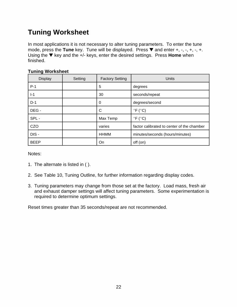
Tuning Worksheet
In most applications it is not necessary to alter tuning parameters. To enter the tunemode, press the Tune key. Tune will be displayed. Press – and enter +, -, -, +, -, +. Using the – key and the +/- keys, enter the desired settings. Press Home whenfinished.
Tuning Worksheet
Display Setting Factory Setting Units
P-1 5 degrees
I-1 30 seconds/repeat
D-1 0 degrees/second
DEG - C EF (EC)
SPL - Max Temp EF (EC)
CZO varies factor calibrated to center of the chamber
DIS - HHMM minutes/seconds (hours/minutes)
BEEP On off (on)
Notes:
1. The alternate is listed in ( ).
2. See Table 10, Tuning Outline, for further information regarding display codes.
3. Tuning parameters may change from those set at the factory. Load mass, fresh airand exhaust damper settings will affect tuning parameters. Some experimentation isrequired to determine optimum settings.
Reset times greater than 35 seconds/repeat are not recommended.
23
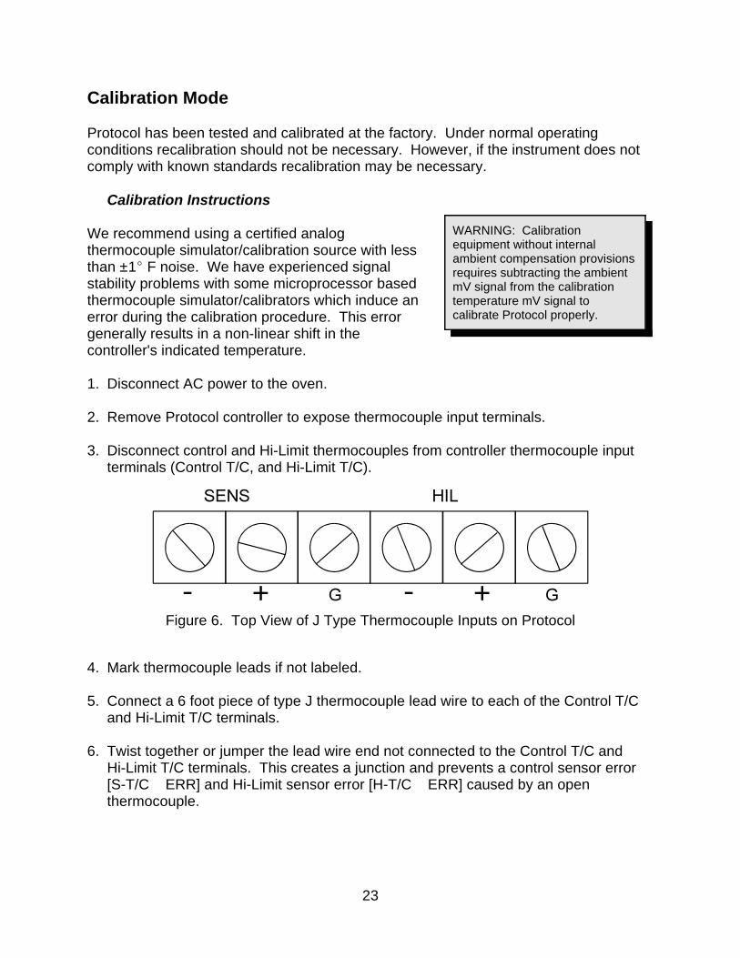
WARNING: Calibrationequipment without internalambient compensation provisionsrequires subtracting the ambientmV signal from the calibrationtemperature mV signal tocalibrate Protocol properly.
Figure 6. Top View of J Type Thermocouple Inputs on Protocol
Calibration Mode
Protocol has been tested and calibrated at the factory. Under normal operatingconditions recalibration should not be necessary. However, if the instrument does notcomply with known standards recalibration may be necessary.
Calibration Instructions
We recommend using a certified analogthermocouple simulator/calibration source with lessthan ±1E F noise. We have experienced signalstability problems with some microprocessor basedthermocouple simulator/calibrators which induce anerror during the calibration procedure. This errorgenerally results in a non-linear shift in thecontroller's indicated temperature.
1. Disconnect AC power to the oven.
2. Remove Protocol controller to expose thermocouple input terminals.
3. Disconnect control and Hi-Limit thermocouples from controller thermocouple inputterminals (Control T/C, and Hi-Limit T/C).
4. Mark thermocouple leads if not labeled.
5. Connect a 6 foot piece of type J thermocouple lead wire to each of the Control T/Cand Hi-Limit T/C terminals.
6. Twist together or jumper the lead wire end not connected to the Control T/C andHi-Limit T/C terminals. This creates a junction and prevents a control sensor error[S-T/C ERR] and Hi-Limit sensor error [H-T/C ERR] caused by an openthermocouple.
24
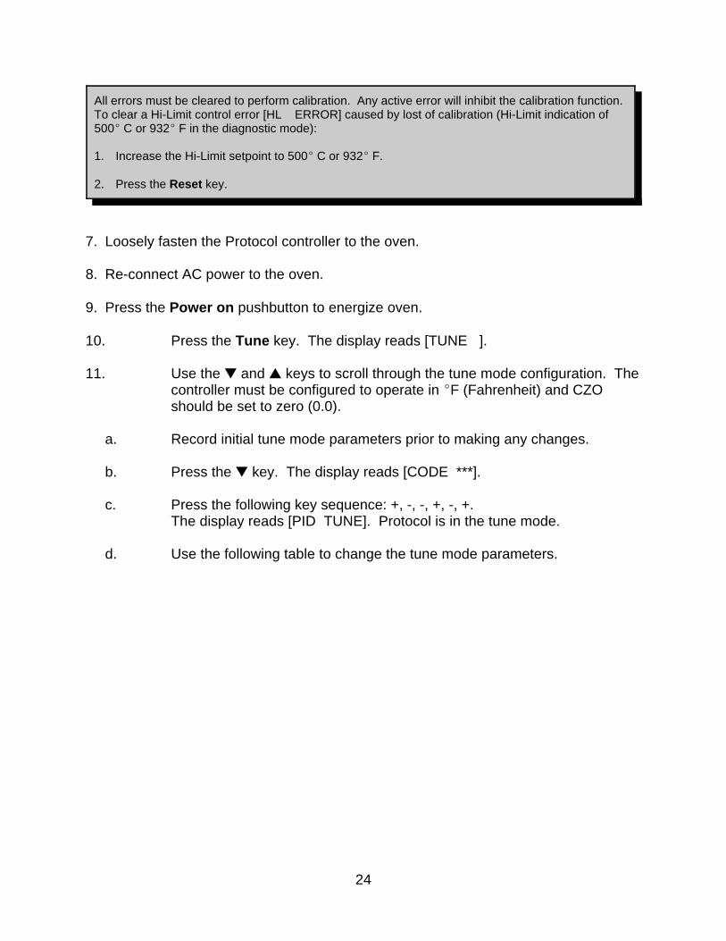
All errors must be cleared to perform calibration. Any active error will inhibit the calibration function. To clear a Hi-Limit control error [HL ERROR] caused by lost of calibration (Hi-Limit indication of500E C or 932E F in the diagnostic mode):
1. Increase the Hi-Limit setpoint to 500E C or 932E F.
2. Press the Reset key.
7. Loosely fasten the Protocol controller to the oven.
8. Re-connect AC power to the oven.
9. Press the Power on pushbutton to energize oven.
10. Press the Tune key. The display reads [TUNE ].
11. Use the – and • keys to scroll through the tune mode configuration. Thecontroller must be configured to operate in EF (Fahrenheit) and CZOshould be set to zero (0.0).
a. Record initial tune mode parameters prior to making any changes.
b. Press the – key. The display reads [CODE ***].
c. Press the following key sequence: +, -, -, +, -, +. The display reads [PID TUNE]. Protocol is in the tune mode.
d. Use the following table to change the tune mode parameters.

25
NOTE: ### or ##.# represents a numeric value or parameter.
Tune Mode Parameter Calibration
Press Display Factory DefaultSetting
ActualSetting
Press Adjustable Range
– key P-1 ### 5 + or - keys 0E C to 500E C32E F to 932E F
– key I-1 ### 30 + or - keys 0 to 999seconds/repeat
– key D-1 ### 0 + or - keys 0 to 999degrees/second
– key DEG - C C + key for C or - key for F.
– key SPL - ### maximum designedoperatingtemperature¹
+ or - keys 0E C to 500E C32E F to 932E F
– key CZO - ##.# can vary + or - keys to changeparameter to 0.0
-99.9 to 99.9degrees
– key DIS HHMM
HHMM + key for HHMM (hoursand minutes) or the - keyfor MMSS (minutes andseconds).
– key BEEP ON ON + key for ON or the - keyfor OFF.
¹ 204E C/400E F, 260E C/500E F, 343E C/650E F
e. Press the Manual key. The display reads [MANUAL ].
f. Allow the controller a thirty (30) minute warm up time before proceeding tothe step #13 - CAL MODE.
12. Press the Cal key. The display reads [CAL--MODE].
13. Press the – key. The display reads [CODE ***].
14. Press the following key sequence: -, +, +, -, +, -. The display reads [HCAL 250].

26
15. Apply a 250E F signal to the high limit thermocouple input:
a. Connect the piece of type J thermocouple lead wire, wired to the HighLimit T/C terminals, to a thermocouple simulator.
b. Set the simulator to output a type J thermocouple signal.
c. Twist together or jumper the piece of type J thermocouple lead wire, wiredto the Control T/C terminals. This creates a junction and prevents aControl sensor error [S-T/C ERR] caused by an open thermocouple. Press the Reset key to clear a Control sensor error [S-T/C ERR] causedby an open thermocouple.
d. Adjust the simulator to supply a 250E F signal. Wait for 30 seconds whilethe control stabilizes.
16. Press the following key sequence: -, -, +. The display now reads HCAL450.
17. Adjust the simulator to supply a 450E F signal. Wait for 30 seconds whilethe control stabilizes.
18. Press the following key sequence: +, +, -. The display now reads HIL 450.
19. To verify proper calibration, adjust the simulator to supply a 350E F signal. Within 30 seconds, the display should stabilize and read HIL 350.
20. To calibrate the control sensor, press the – key. The display reads[SCAL 250].
21. Apply a 250E F signal to the control thermocouple input:
a. Connect the piece of type J thermocouple lead wire, wired to the SensorT/C terminals, to a thermocouple simulator.
b. The simulator should be set to output a type J thermocouple signal.
c. Twist together or jumper the piece of type J thermocouple lead wire to theHi-Limit T/C terminals. This creates a junction and prevents a hi-limitsensor error [H-T/C ERR] caused by an open thermocouple. Press theReset key to clear a hi-limit sensor error [H-T/C ERR] caused by anopen thermocouple.
d. Adjust the simulator to supply a 250E F signal. Wait for 30 seconds whilethe control stabilizes.
27
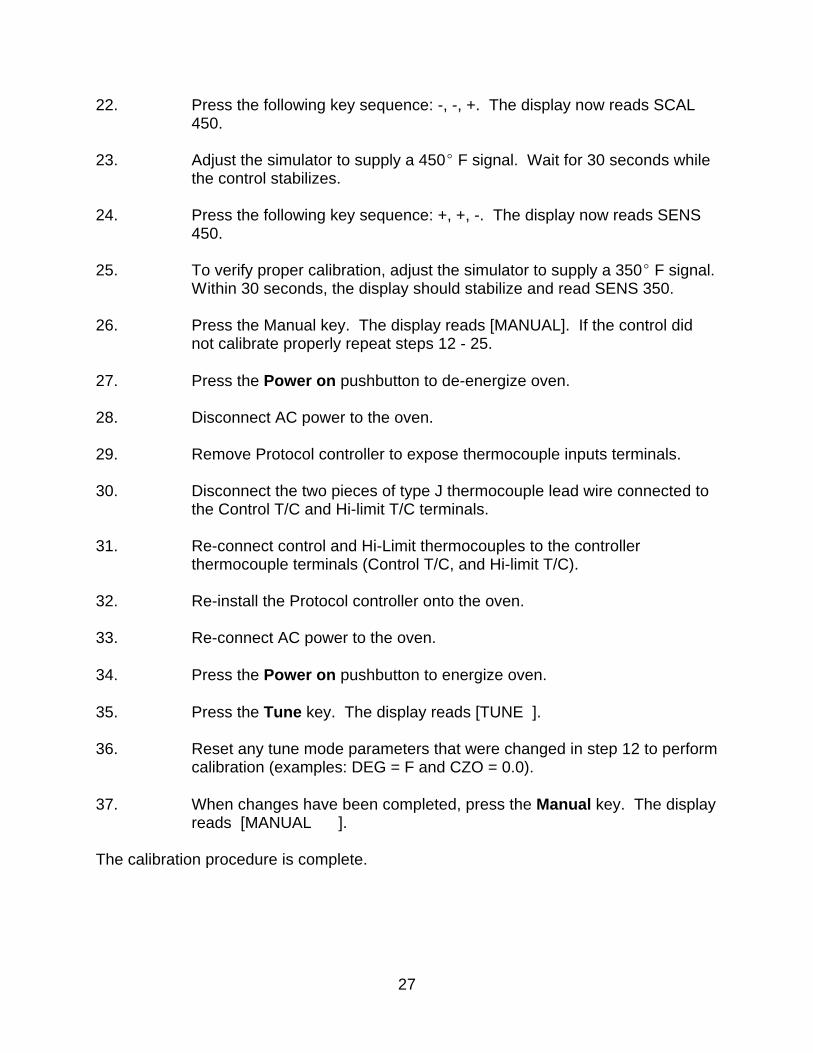
22. Press the following key sequence: -, -, +. The display now reads SCAL450.
23. Adjust the simulator to supply a 450E F signal. Wait for 30 seconds whilethe control stabilizes.
24. Press the following key sequence: +, +, -. The display now reads SENS450.
25. To verify proper calibration, adjust the simulator to supply a 350E F signal. Within 30 seconds, the display should stabilize and read SENS 350.
26. Press the Manual key. The display reads [MANUAL]. If the control didnot calibrate properly repeat steps 12 - 25.
27. Press the Power on pushbutton to de-energize oven.
28. Disconnect AC power to the oven.
29. Remove Protocol controller to expose thermocouple inputs terminals.
30. Disconnect the two pieces of type J thermocouple lead wire connected tothe Control T/C and Hi-limit T/C terminals.
31. Re-connect control and Hi-Limit thermocouples to the controllerthermocouple terminals (Control T/C, and Hi-limit T/C).
32. Re-install the Protocol controller onto the oven.
33. Re-connect AC power to the oven.
34. Press the Power on pushbutton to energize oven.
35. Press the Tune key. The display reads [TUNE ].
36. Reset any tune mode parameters that were changed in step 12 to performcalibration (examples: DEG = F and CZO = 0.0).
37. When changes have been completed, press the Manual key. The displayreads [MANUAL ].
The calibration procedure is complete.
28
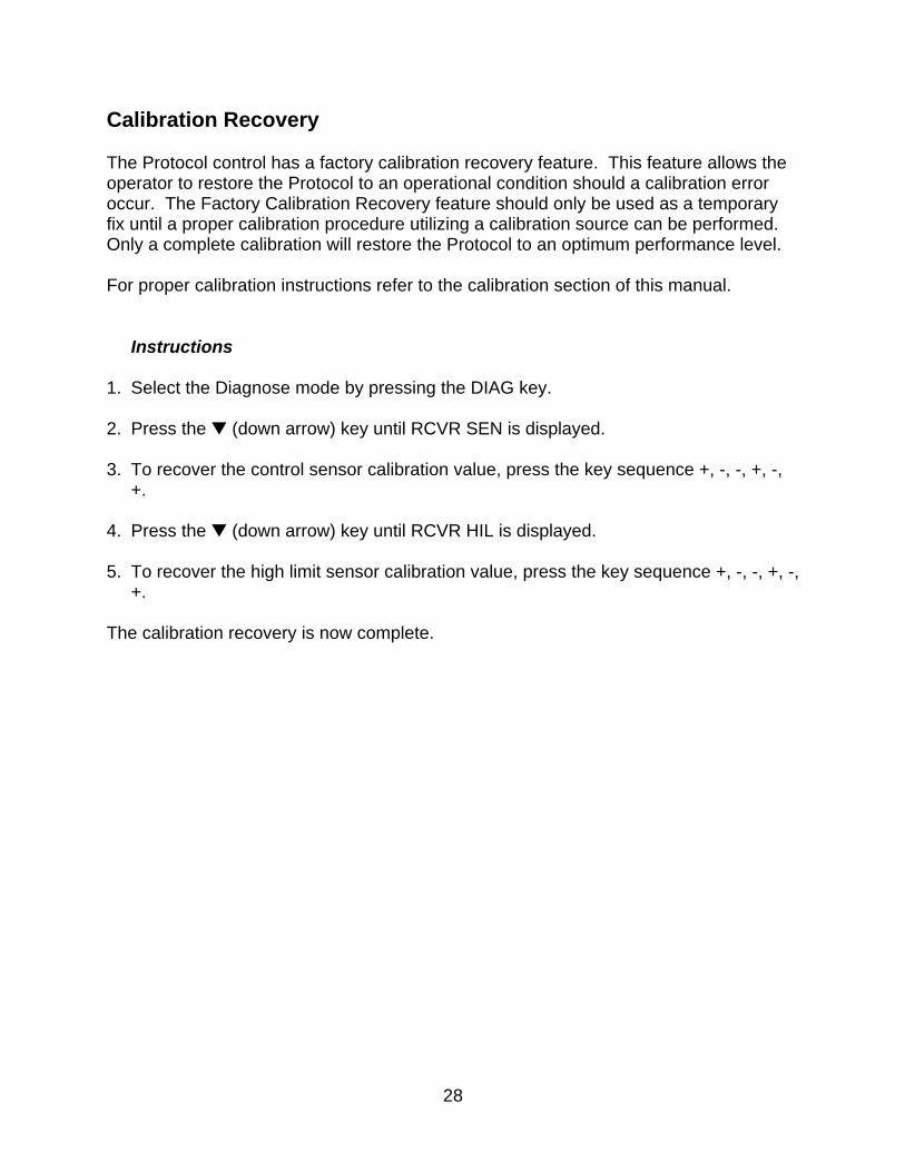
Calibration Recovery
The Protocol control has a factory calibration recovery feature. This feature allows theoperator to restore the Protocol to an operational condition should a calibration erroroccur. The Factory Calibration Recovery feature should only be used as a temporaryfix until a proper calibration procedure utilizing a calibration source can be performed. Only a complete calibration will restore the Protocol to an optimum performance level.
For proper calibration instructions refer to the calibration section of this manual.
Instructions
1. Select the Diagnose mode by pressing the DIAG key.
2. Press the – (down arrow) key until RCVR SEN is displayed.
3. To recover the control sensor calibration value, press the key sequence +, -, -, +, -,+.
4. Press the – (down arrow) key until RCVR HIL is displayed.
5. To recover the high limit sensor calibration value, press the key sequence +, -, -, +, -,+.
The calibration recovery is now complete.
29
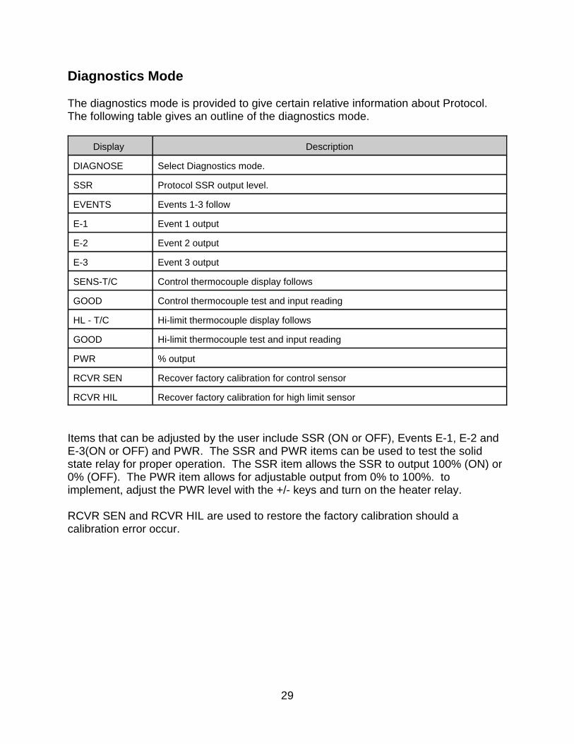
Diagnostics Mode
The diagnostics mode is provided to give certain relative information about Protocol. The following table gives an outline of the diagnostics mode.
Display Description
DIAGNOSE Select Diagnostics mode.
SSR Protocol SSR output level.
EVENTS Events 1-3 follow
E-1 Event 1 output
E-2 Event 2 output
E-3 Event 3 output
SENS-T/C Control thermocouple display follows
GOOD Control thermocouple test and input reading
HL - T/C Hi-limit thermocouple display follows
GOOD Hi-limit thermocouple test and input reading
PWR % output
RCVR SEN Recover factory calibration for control sensor
RCVR HIL Recover factory calibration for high limit sensor
Items that can be adjusted by the user include SSR (ON or OFF), Events E-1, E-2 andE-3(ON or OFF) and PWR. The SSR and PWR items can be used to test the solidstate relay for proper operation. The SSR item allows the SSR to output 100% (ON) or0% (OFF). The PWR item allows for adjustable output from 0% to 100%. toimplement, adjust the PWR level with the +/- keys and turn on the heater relay.
RCVR SEN and RCVR HIL are used to restore the factory calibration should acalibration error occur.

30
Power Failure
In the event that the power supplied to Protocol is insufficient at any point during arunning mode, the display will read PWR-FAIL. In the tune mode the user can choosethe Power Fail Recovery mode from Stop, Resume and Hold. To restart after a powerfailure in the hold mode, press the Start key to resume oven operation. Otherwise,press the Reset key to clear the PWR-FAIL display. Do not shut off the power during arunning mode. This creates an error condition and PWR-FAIL will be displayed thenext time Protocol is powered up. Instead, press the Stop key and the Heater Off key. This will power off Protocol without creating an error condition.
31
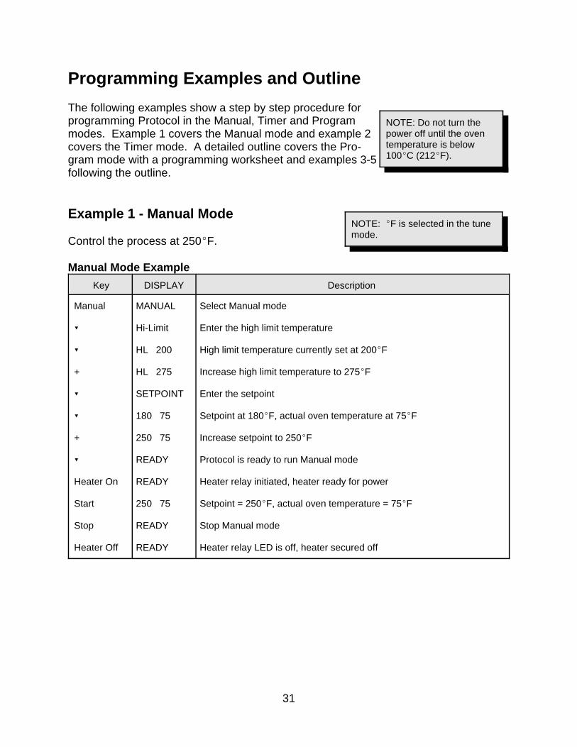
NOTE: Do not turn thepower off until the oventemperature is below100EC (212EF).
NOTE: EF is selected in the tunemode.
Programming Examples and Outline
The following examples show a step by step procedure forprogramming Protocol in the Manual, Timer and Programmodes. Example 1 covers the Manual mode and example 2covers the Timer mode. A detailed outline covers the Pro-gram mode with a programming worksheet and examples 3-5following the outline.
Example 1 - Manual Mode
Control the process at 250EF.
Manual Mode Example
Key DISPLAY Description
Manual
?
?
+
?
?
+
?
Heater On
Start
Stop
Heater Off
MANUAL
Hi-Limit
HL 200
HL 275
SETPOINT
180 75
250 75
READY
READY
250 75
READY
READY
Select Manual mode
Enter the high limit temperature
High limit temperature currently set at 200EF
Increase high limit temperature to 275EF
Enter the setpoint
Setpoint at 180EF, actual oven temperature at 75EF
Increase setpoint to 250EF
Protocol is ready to run Manual mode
Heater relay initiated, heater ready for power
Setpoint = 250EF, actual oven temperature = 75EF
Stop Manual mode
Heater relay LED is off, heater secured off
32
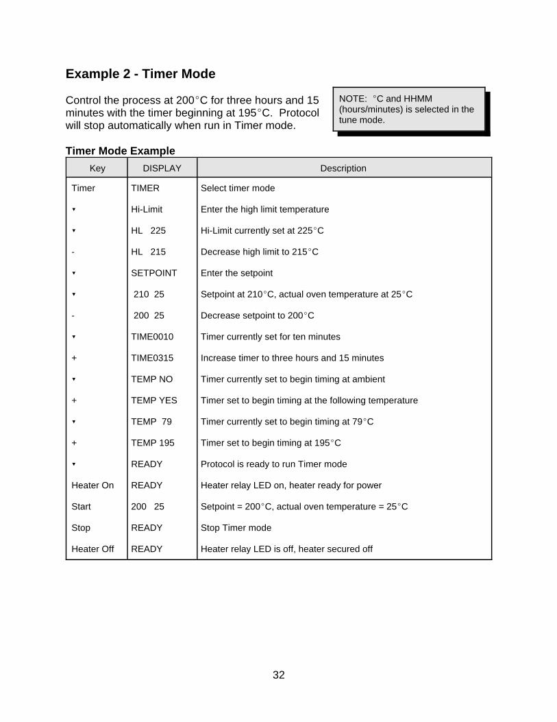
NOTE: EC and HHMM(hours/minutes) is selected in thetune mode.
Example 2 - Timer Mode
Control the process at 200EC for three hours and 15minutes with the timer beginning at 195EC. Protocolwill stop automatically when run in Timer mode.
Timer Mode Example
Key DISPLAY Description
Timer
?
?
-
?
?
-
?
+
?
+
?
+
?
Heater On
Start
Stop
Heater Off
TIMER
Hi-Limit
HL 225
HL 215
SETPOINT
210 25
200 25
TIME0010
TIME0315
TEMP NO
TEMP YES
TEMP 79
TEMP 195
READY
READY
200 25
READY
READY
Select timer mode
Enter the high limit temperature
Hi-Limit currently set at 225EC
Decrease high limit to 215EC
Enter the setpoint
Setpoint at 210EC, actual oven temperature at 25EC
Decrease setpoint to 200EC
Timer currently set for ten minutes
Increase timer to three hours and 15 minutes
Timer currently set to begin timing at ambient
Timer set to begin timing at the following temperature
Timer currently set to begin timing at 79EC
Timer set to begin timing at 195EC
Protocol is ready to run Timer mode
Heater relay LED on, heater ready for power
Setpoint = 200EC, actual oven temperature = 25EC
Stop Timer mode
Heater relay LED is off, heater secured off

33
Program Mode
Program Mode OutlineDisplay Description
PROGRAM
Hi-Limit
HL
PROFILES PRO-
SEG-
RAMP
EVENTS E-1 E-2 E-3
TEMP
SOAK EVENTS E-1 E-2 E-3
SOAK-DEV
+/-
GOTO
REPEAT TIMES
HOLD
YES
NO
Select Program mode.
Hi-Limit for Program mode
Enter high limit temperature (+ or - keys).
Enter profile number (1-8).
Segment number of profile (1-6)
Ramp time entered
Event status for ramp timeEvent 1 status (ON or OFF)Event 2 status (ON or OFF)Event 3 status (ON or OFF)
Ramp ending temperature
Soak period of ramp ending temperature
Event status for soak periodEvent 1 status (ON or OFF)Event 2 status (ON or OFF)Event 3 status (ON or OFF)
Soak-Deviation limit for profile (Also assured soak limit)
Enter soak-deviation limit.
Enter profile to GOTO End = Move to REPEAT TIMES command 1 = GOTO profile 1 2 = GOTO profile 2 : 8 = GOTO profile 8
Enter number of recursions (1-99) 1 = Execute profile 1 times 2 = Execute profile 2 times : 99 = Execute profile 99 times
Hold at last setpoint?
Hold at last setpoint indefinitely. Holds event outputs at last value.
No hold at last setpoint. Event outputs turn OFF.
Notes on the Program mode:
34
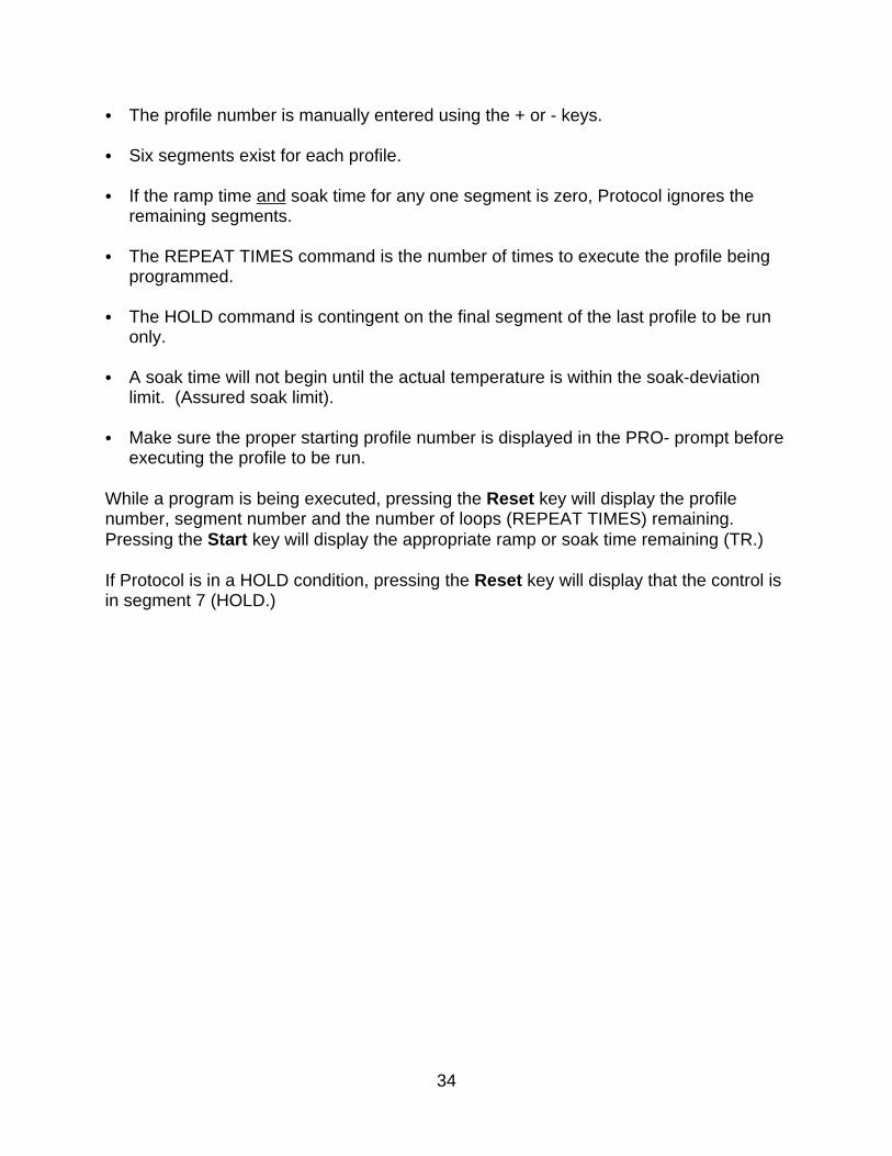
C The profile number is manually entered using the + or - keys.
C Six segments exist for each profile.
C If the ramp time and soak time for any one segment is zero, Protocol ignores theremaining segments.
C The REPEAT TIMES command is the number of times to execute the profile beingprogrammed.
C The HOLD command is contingent on the final segment of the last profile to be runonly.
C A soak time will not begin until the actual temperature is within the soak-deviationlimit. (Assured soak limit).
C Make sure the proper starting profile number is displayed in the PRO- prompt beforeexecuting the profile to be run.
While a program is being executed, pressing the Reset key will display the profilenumber, segment number and the number of loops (REPEAT TIMES) remaining. Pressing the Start key will display the appropriate ramp or soak time remaining (TR.)
If Protocol is in a HOLD condition, pressing the Reset key will display that the control isin segment 7 (HOLD.)
35
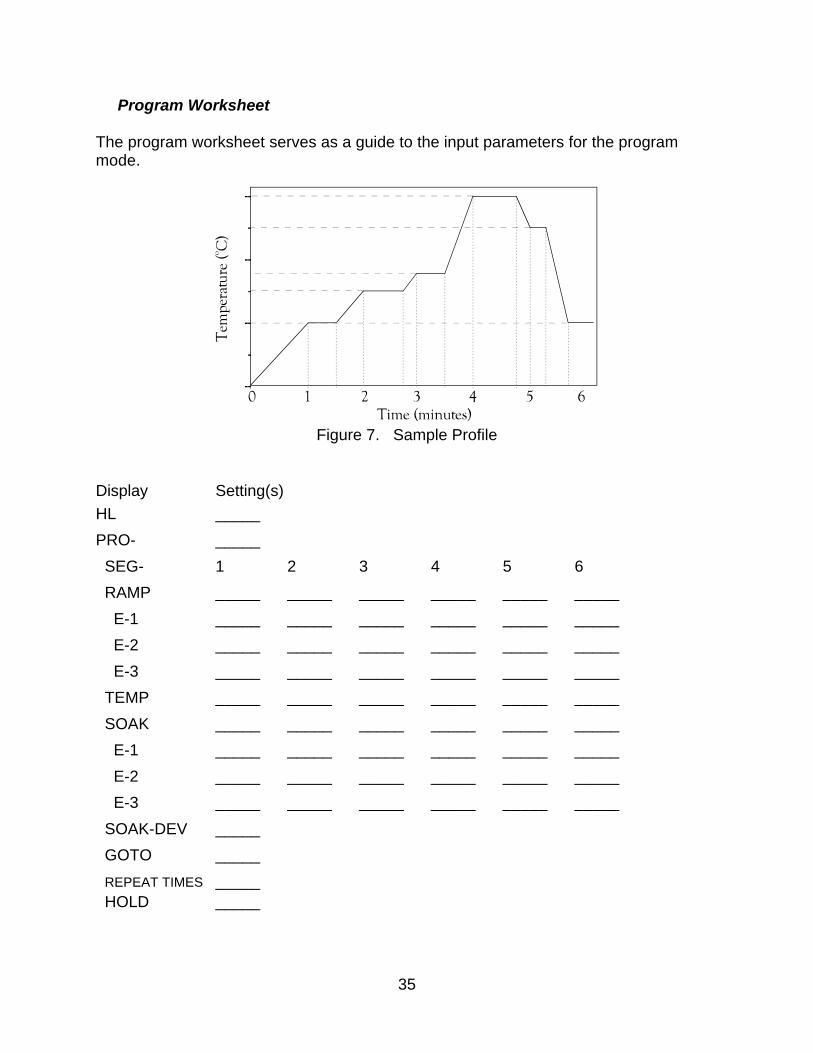
Figure 7. Sample Profile
Program Worksheet
The program worksheet serves as a guide to the input parameters for the programmode.
Display Setting(s)
HL _____
PRO- _____
SEG- 1 2 3 4 5 6
RAMP _____ _____ _____ _____ _____ _____
E-1 _____ _____ _____ _____ _____ _____
E-2 _____ _____ _____ _____ _____ _____
E-3 _____ _____ _____ _____ _____ _____
TEMP _____ _____ _____ _____ _____ _____
SOAK _____ _____ _____ _____ _____ _____
E-1 _____ _____ _____ _____ _____ _____
E-2 _____ _____ _____ _____ _____ _____
E-3 _____ _____ _____ _____ _____ _____
SOAK-DEV _____
GOTO _____
REPEAT TIMES _____ HOLD _____
36
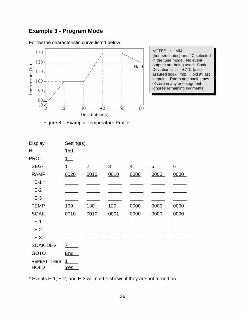
Figure 8. Example Temperature Profile
NOTES: HHMM(hours/minutes) and EC selectedin the tune mode. No eventoutputs are being used. Soak-Deviation limit = ±7EC (alsoassured soak limit). Hold at lastsetpoint. Ramp and soak timesof zero in any one segmentignores remaining segments.
Example 3 - Program Mode
Follow the characteristic curve listed below.
Display Setting(s)
HL 150
PRO- 1
SEG- 1 2 3 4 5 6
RAMP 0020 0010 0010 0000 0000 0000
E-1 * _____ _____ _____ _____ _____ _____
E-2 _____ _____ _____ _____ _____ _____
E-3 _____ _____ _____ _____ _____ _____
TEMP 100 130 120 0000 0000 0000
SOAK 0010 0010 0001 0000 0000 0000
E-1 _____ _____ _____ _____ _____ _____
E-2 _____ _____ _____ _____ _____ _____
E-3 _____ _____ _____ _____ _____ _____
SOAK-DEV 7
GOTO End
REPEAT TIMES 1 HOLD Yes
* Events E-1, E-2, and E-3 will not be shown if they are not turned on.

37
Figure 9. Example Temperature Profile
NOTES: MMSS(minutes/seconds) and EFselected in the tune mode. Event1 wired properly for autostart,events 2 - 3 are not used. Nohold at last setpoint.
Soak-Deviation = ±5EF (alsoassured soak limit). Minimumoperating temperature is 70EF.
Example 4 - Program Mode
Autostart the oven after two hours and follow the characteristic curve below.
Display Setting(s)
HL 240
PRO- 1
SEG- 1 2 3 4 5 6
RAMP 0001 0100 0030 0100 0100 0030
E-1 * OFF ON ON ON ON ON
E-2 _____ _____ _____ _____ _____ _____
E-3 _____ _____ _____ _____ _____ _____
TEMP 70 130 160 130 220 100
SOAK 0200 0030 0100 0100 0200 0001
E-1 OFF ON ON ON ON OFF
E-2 _____ _____ _____ _____ _____ _____
E-3 _____ _____ _____ _____ _____ _____
SOAK-DEV 5
GOTO End
REPEAT TIMES 1____
HOLD NO
* Only E1 event is turned on.
38
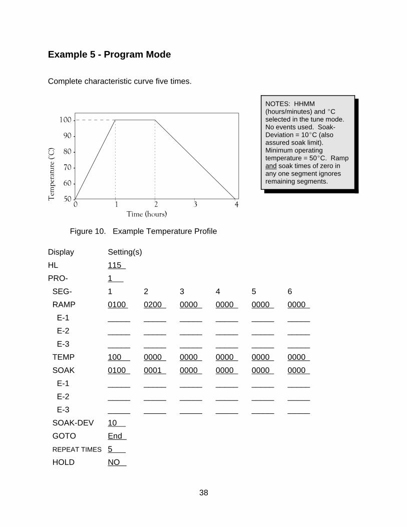
NOTES: HHMM(hours/minutes) and ECselected in the tune mode. No events used. Soak-Deviation = 10EC (alsoassured soak limit). Minimum operatingtemperature = 50EC. Rampand soak times of zero inany one segment ignoresremaining segments.
Figure 10. Example Temperature Profile
Example 5 - Program Mode
Complete characteristic curve five times.
Display Setting(s)
HL 115
PRO- 1
SEG- 1 2 3 4 5 6
RAMP 0100 0200 0000 0000 0000 0000
E-1 _____ _____ _____ _____ _____ _____
E-2 _____ _____ _____ _____ _____ _____
E-3 _____ _____ _____ _____ _____ _____
TEMP 100 0000 0000 0000 0000 0000
SOAK 0100 0001 0000 0000 0000 0000
E-1 _____ _____ _____ _____ _____ _____
E-2 _____ _____ _____ _____ _____ _____
E-3 _____ _____ _____ _____ _____ _____
SOAK-DEV 10
GOTO End
REPEAT TIMES 5
HOLD NO
39
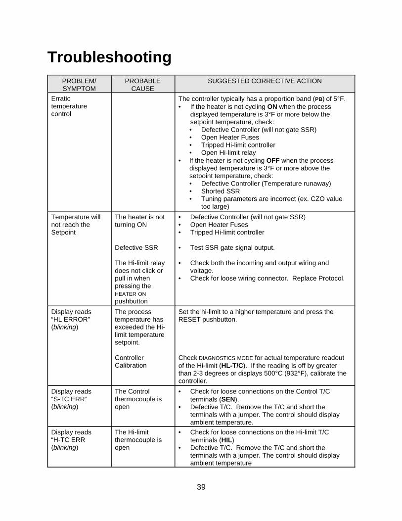
TroubleshootingPROBLEM/SYMPTOM
PROBABLECAUSE
SUGGESTED CORRECTIVE ACTION
Erratictemperaturecontrol
The controller typically has a proportion band (PB) of 5°F.• If the heater is not cycling ON when the process
displayed temperature is 3°F or more below thesetpoint temperature, check:• Defective Controller (will not gate SSR)• Open Heater Fuses• Tripped Hi-limit controller• Open Hi-limit relay
• If the heater is not cycling OFF when the processdisplayed temperature is 3°F or more above thesetpoint temperature, check:• Defective Controller (Temperature runaway)• Shorted SSR• Tuning parameters are incorrect (ex. CZO value
too large)
Temperature willnot reach theSetpoint
The heater is notturning ON
Defective SSR
The Hi-limit relaydoes not click orpull in whenpressing theHEATER ON
pushbutton
• Defective Controller (will not gate SSR)• Open Heater Fuses• Tripped Hi-limit controller
• Test SSR gate signal output.
• Check both the incoming and output wiring andvoltage.
• Check for loose wiring connector. Replace Protocol.
Display reads “HL ERROR”(blinking)
The processtemperature hasexceeded the Hi-limit temperaturesetpoint.
ControllerCalibration
Set the hi-limit to a higher temperature and press theRESET pushbutton.
Check DIAGNOSTICS MODE for actual temperature readoutof the Hi-limit (HL-T/C). If the reading is off by greaterthan 2-3 degrees or displays 500°C (932°F), calibrate thecontroller.
Display reads “S-TC ERR”(blinking)
The Controlthermocouple isopen
• Check for loose connections on the Control T/Cterminals (SEN).
• Defective T/C. Remove the T/C and short theterminals with a jumper. The control should displayambient temperature.
Display reads“H-TC ERR(blinking)
The Hi-limitthermocouple isopen
• Check for loose connections on the Hi-limit T/Cterminals (HIL)
• Defective T/C. Remove the T/C and short theterminals with a jumper. The control should displayambient temperature
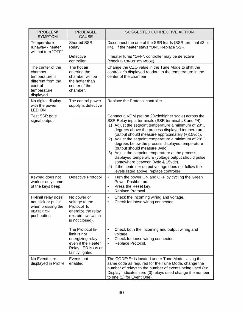
PROBLEM/SYMPTOM
PROBABLECAUSE
SUGGESTED CORRECTIVE ACTION
40
Temperaturerunaway - heaterwill not turn "OFF"
Shorted SSRRelay
Defectivecontroller
Disconnect the one of the SSR leads (SSR terminal #3 or#4). If the heater stays "ON", Replace SSR.
If heater turns "OFF", controller may be defective(check DIAGNOSTICS MODE).
The center of thechambertemperature isdifferent from thecontroltemperaturedisplayed
The hot airentering thechamber will bethe hotter thancenter of thechamber.
Change the CZO value in the Tune Mode to shift thecontroller’s displayed readout to the temperature in thecenter of the chamber.
No digital display with the powerLED ON
The control powersupply is defective
Replace the Protocol controller.
Test SSR gatesignal output
Connect a VOM (set on 20vdc/higher scale) across theSSR Relay input terminals (SSR terminal #3 and #4) 1) Adjust the setpoint temperature a minimum of 20°C
degrees above the process displayed temperature(output should measure approximately (+)15vdc).
2) Adjust the setpoint temperature a minimum of 20°Cdegrees below the process displayed temperature(output should measure 0vdc).
3) Adjust the setpoint temperature at the processdisplayed temperature (voltage output should pulsesomewhere between 0vdc & 15vdc).
4) If the controller output voltage does not follow thelevels listed above, replace controller.
Keypad does notwork or only someof the keys beep
Defective Protocol • Turn the power ON and OFF by cycling the GreenPower Pushbutton.
• Press the Reset key.• Replace Protocol.
Hi-limit relay doesnot click or pull inwhen pressing theHEATER ON
pushbutton
No power orvoltage to theProtocol toenergize the relay(ex. airflow switchis not closed).
The Protocol hi-limit is notenergizing relayeven if the HeaterRelay LED is ON orfaintly lighted.
• Check the incoming wiring and voltage.• Check for loose wiring connector.
• Check both the incoming and output wiring andvoltage.
• Check for loose wiring connector.• Replace Protocol.
No Events aredisplayed in Profile
Events notenabled
The CODE*E* is located under Tune Mode. Using thesame code as required for the Tune Mode, change thenumber of relays to the number of events being used (ex.Display indicates zero (0) relays used change the numberto one (1) for Event One).

PROBLEM/SYMPTOM
PROBABLECAUSE
SUGGESTED CORRECTIVE ACTION
41
Control or Hi-limitreadout displays500°C or 932°F
Loss of calibration Perform calibration.