Embed Size (px)
DESCRIPTION
Descrierea protocoalelor EuroNCAP in cazul simularii si efectuarii testelor de coliziune frontala in cazul accidentelor rutiere
Citation preview

EUROPEAN NEW CAR ASSESSMENT PROGRAMME
(Euro NCAP)
FULL WIDTH FRONTAL IMPACT
TESTING PROTOCOL
Version 1.0.1
April 2015

Version 1.0.1
April 2015 4
Copyright 2015 ©Euro NCAP - This work is the intellectual property of Euro NCAP. Permission is granted for
this material to be shared for non-commercial, educational purposes, provided that this copyright statement
appears on the reproduced materials and notice is given that the copying is by permission of Euro NCAP. To
disseminate otherwise or to republish requires written permission from Euro NCAP.
Version 1.0.1
April 2015 5
Preface
During the test preparation, vehicle manufacturers are encouraged to liaise with the
laboratory and to check that they are satisfied with the way cars are set up for testing. Where
a manufacturer feels that a particular item should be altered, they should ask the laboratory
staff to make any necessary changes. Manufacturers are forbidden from making changes to
any parameter that will influence the test, such as dummy positioning, vehicle setting,
laboratory environment etc.
It is the responsibility of the test laboratory to ensure that any requested changes satisfy the
requirements of Euro NCAP. Where a disagreement exists between the laboratory and
manufacturer, the Euro NCAP secretariat should be informed immediately to pass final
judgment. Where the laboratory staff suspect that a manufacturer has interfered with any of
the set up, the manufacturer's representative should be warned that they are not allowed to do
so themselves. They should also be informed that if another incident occurs, they will be
asked to leave the test site.
Where there is a recurrence of the problem, the manufacturer’s representative will be told to
leave the test site and the Secretary General should be immediately informed. Any such
incident may be reported by the Secretary General to the manufacturer and the person
concerned may not be allowed to attend further Euro NCAP tests.
DISCLAIMER: Euro NCAP has taken all reasonable care to ensure that the information
published in this protocol is accurate and reflects the technical decisions taken by the
organisation. In the unlikely event that this protocol contains a typographical error or any
other inaccuracy, Euro NCAP reserves the right to make corrections and determine the
assessment and subsequent result of the affected requirement(s).
Version 1.0.1
April 2015 6
Table of Contents Page No.
1 VEHICLE PREPARATION 7
1.1 Unladen Kerb Mass 7
1.2 Reference Loads 7
1.3 Vehicle Width 8
1.4 Vehicle Preparation 8
2 INTRUSION MEASUREMENTS 10
2.1 Before Test 10
2.2 After Test 11
3 DUMMY PREPARATION AND CERTIFICATION 13
3.1 General 13
3.2 Additions and Modifications to the Hybrid III Dummies 13
3.3 Dummy Certification 13
3.4 Dummy Clothing and Footwear 14
3.5 Dummy Test Condition 14
3.6 Post Test Dummy Inspection 15
4 INSTRUMENTATION 16
4.1 Dummy Instrumentation 16
4.2 Vehicle Instrumentation 17
4.3 Summary of Total Channels 17
5 PASSENGER COMPARTMENT ADJUSTMENTS 18
5.1 Driver Compartment Adjustments 18
5.2 Rear Passenger Seat Adjustments 19
5.3 Other Vehicle Adjustments 19
5.4 Driver Seating Position for Test 19
5.5 Front Passenger Seating Position for Test 20
5.6 Setting the Steering Wheel Horizontal Adjustment 21
5.7 Setting the Steering Wheel Vertical Adjustment 21
5.8 Setting the Rear Seat (if adjustable) 21
5.9 Marking the Rear Dummy Head Excursion Line 21
6 DUMMY POSITIONING AND MEASUREMENTS 22
6.1 Determine the H-point 22
6.2 Dummy Placement 23
6.3 Driver Dummy Positioning 24
6.4 Rear Passenger Dummy Positioning 26
6.5 Dummy Measurements 28
7 TEST PARAMETERS 29
7.1 Barrier 29
7.2 Speed 29
7.3 Door Opening Force 29
7.4 Dummy Removal 30
7.5 Intrusion Measurements 30
Version 1.0.1
April 2015 7
1 VEHICLE PREPARATION
1.1 Unladen Kerb Mass
1.1.1 The capacity of the fuel tank will be specified by the manufacturer. This volume will
be referred to throughout as the “fuel tank capacity”.
1.1.2 Syphon most of the fuel from the tank and then run the car until it has run out of fuel.
1.1.3 Calculate the mass of the fuel tank capacity using a density for petrol of 0.745g/ml or
0.840g/ml for diesel. Record this figure in the test details.
1.1.4 Put water, or other ballast, to this mass in the fuel tank.
1.1.5 Check the oil level and top up to its maximum level if necessary. Similarly, top up the
levels of all other fluids to their maximum levels if necessary.
1.1.6 Ensure that the vehicle has its spare wheel on board along with any tools supplied with
the vehicle. Nothing else should be in the car.
1.1.7 Ensure that all tyres are inflated according to the manufacturer’s instructions for half
load.
1.1.8 Measure the front and rear axle weights and determine the total weight of the vehicle.
The total weight is the ‘unladen kerb mass’ of the vehicle. Record this mass in the test
details.
1.1.9 Measure and record the ride heights of the vehicle at all four wheels.
1.2 Reference Loads
1.2.1 Calculate 10 percent of the fuel tank capacity mass as determined in 1.1.3.
1.2.2 Remove this mass of ballast from the fuel tank, leaving 90 percent of the mass in the
tank.
1.2.3 Place both front seats in their mid-positions. If there is no notch at this position, set the
seat in the nearest notch rearward (this will be done more completely in Section 6).
1.2.4 Place a mass of equivalent to a Hybrid-III 05F dummy (57kg with instrumentation and
cables) on the front driver seat and on the rear passenger seat at the opposite side.
1.2.5 Place 36kg in the luggage compartment of the vehicle. The normal luggage
compartment should be used i.e. rear seats should not be folded to increase the luggage
capacity. Spread the weights as evenly as possible over the base of the luggage
compartment. If the weights cannot be evenly distributed, concentrate weights towards
the centre of the compartment.
1.2.6 For two seater vehicles only, the mass of the rear passenger shall not be included in the
reference load. For vehicles with limited rear space, the rear passenger dummy shall be
included in the reference load.
1.2.7 Roll the vehicle back and forth to ‘settle’ the tyres and suspension with the extra
weight on board. Weigh the front and rear axle weights of the vehicle. These loads are
the “axle reference loads” and the total weight is the “reference mass” of the vehicle.
1.2.8 Record the axle reference loads and reference mass in the test details.
1.2.9 Record the ride-heights of the vehicle at the point on the wheel arch in the same
transverse plane as the wheel centres. Do this for all four wheels.
1.2.10 Remove the weights from the luggage compartment and the front and rear seats.
Version 1.0.1
April 2015 8
1.3 Vehicle Width
1.3.1 Determine the widest point of the vehicle ignoring the rear-view mirrors, side marker
lamps, tyre pressure indicators, direction indicator lamps, position lamps, flexible
mud-guards and the deflected part of the tyre side-walls immediately above the point
of contact with the ground.
1.3.2 Record this width in test details.
1.3.3 Determine the centre-line of the vehicle and mark a line on the bonnet and bumper on
the centre line of the car.
Take the pre-impact vehicle intrusion measurements at this point in time. See
Chapter 2 for a full description of how to do this.
1.4 Vehicle Preparation
Care should be taken during vehicle preparation that the ignition is not switched on
with the battery or airbag disconnected. This will result in an airbag warning light
coming on and the airbag system will need to be reset. The manufacturer will need to
be contacted if this occurs.
1.4.1 Ensure that the vehicle’s battery is connected to the vehicle’s electrical circuit in its
standard position. Check that the dashboard light for the airbag circuit functions as
normal. Alternatively, the vehicle battery acid may be drained or an additional live
battery may be placed in the luggage compartment of the vehicle. If the supply from
the drained battery is not supported by an additional battery, the test must be conducted
within fifteen minutes after draining the battery. Where any additional battery is used it
must be connected directly to the original battery so that the vehicle’s original
electrical system, cable routing and connections remain unaltered. The power cables
connecting both batteries must be positioned on the non-struck side of the car in such a
way to minimise the risk of the cable being cut during the impact. The cable used to
connect both batteries must have a minimum cross section of 5mm2 to ensure a
minimum voltage drop. The current supplied to the vehicle must be monitored
throughout the impact across the original battery. Where an additional battery is to be
used the vehicle manufacturer will be required to indicate the minimum voltage/current
needed during the test for all systems to operate as intended. The manufacturer will be
asked to confirm that the laboratory modifications are suitable for use in the vehicle
being tested and will not influence any of the vehicle systems.
1.4.2 In the event that the engine fluids are to be drained then drain the coolant, oil, air-
conditioning (air conditioning refrigerant should be drained without venting it to the
atmosphere) and Power Assisted Steering (PAS) fluids.
1.4.3 If the fluids are drained then measure the weights of each of these fluids, excluding the
air conditioning fluid, and replace with an equivalent weight of water or other ballast.
1.4.4 Remove the luggage area carpeting, spare wheel and any tools or jack from the car.
The spare wheel should only be removed if it will not affect the crash performance of
the vehicle.
1.4.5 An emergency abort braking system may be fitted to the vehicle. This is optional; the
test facility may elect to test without an abort system. Where such a system is fitted its
inclusion shall not influence the operation or function of any of the foot controls, in
particular the brake pedal. The position and the resistance to movement of the pedals
shall be the same as prior to fitment of the system. Remove as little as possible of the
interior trim; any mass compensation will be made when all equipment has been fitted.
Version 1.0.1
April 2015 9
1.4.6 Fit the on-board data acquisition equipment in the boot of the car. Also fit any
associated cables, cabling boxes and power sources.
1.4.7 Place weights equivalent to a Hybrid-III 05F dummy (57kg) on the front driver seat
and on the rear passenger seat at the opposite side of the car (with the seats in their test
positions).
1.4.8 Weigh the front and rear axle weights of the vehicle. Compare these weights with
those determined in Section 1.2.7.
1.4.9 If the axle weights differ from those measured in Section 1.2.7 by more than 5% (of
the axle reference loads) or by more than 20kg, remove or add items which do not
influence the structural crash performance of the vehicle. Similarly, if the total vehicle
mass differs by more than 25kg from the reference mass, non-structural items may be
removed or added. The levels of ballast in the fuel tank (equivalent in mass to 90%
capacity of fuel) may also be adjusted to help achieve the desired axle weights. Any
additional mass that is added to the vehicle should be securely and rigidly attached.
1.4.10 Repeat Sections 1.4.8 and 1.4.9 until the front and rear axle weights and the total
vehicle weight are within the limits set in 1.4.9. Record the final axle weights in the
test details.
1.4.11 The vehicle manufacturer will be required to inform Euro NCAP and the test
laboratory of the presence of any pre-crash systems that must be disabled prior to
impact. Disabling information shall be provided to the laboratory prior to impact. It is
the responsibility of the vehicle manufacturer to ensure that the disconnection of the
system does not influence the performance of any systems that are intended to function
during the impact.
Version 1.0.1
April 2015 10
2 INTRUSION MEASUREMENTS
For vehicle deformation and intrusion measurements a 3D measuring system which is
capable of recording 3 dimensional co-ordinates of a point in space can be used. A
tolerance of +/- 1mm is applicable to such a system. The system requires an axis
system to be set up relative to the object to be measured, typically the transverse,
longitudinal and vertical directions of a vehicle. An origin is first needed, followed by
a point on the positive x axis and then a point in the positive x-y plane. Since the front
of the vehicle is highly deformed after the impact, it is simplest to use some structure
at the rear of the vehicle as a reference for measurement; this obviates the need to level
the car after testing, the accuracy of which is limited. Most of the procedure which
follows relates to the setting up of these axes.
2.1 Before Test
2.1.1 Determine and mark the centre of the clutch, brake and accelerator pedals.
2.1.2 Set the steering wheel to its mid-position, if it is adjustable for either rake or reach (for
full description of how to do this, see Chapter 5).
2.1.3 Remove the centre of the steering wheel or, if fitted, the airbag assembly to expose the
end of the steering column. When doing this, carefully note the connections to the
airbag which will need to be remade on re-assembly. Follow the manufacturer's
instructions when removing the airbag and/or steering wheel assemblies.
2.1.4 Determine and mark the centre of the top of the steering-column.
2.1.5 Remove the carpet, trim and spare wheel from the luggage compartment. The plastic
trim or rubber seals that might influence the latching mechanism should be re-fitted
once the intrusion measurements have been recorded. This is to ensure that any
opening of the rear door during the impact is not caused by the omission of some part
of the trim around the latching mechanism.
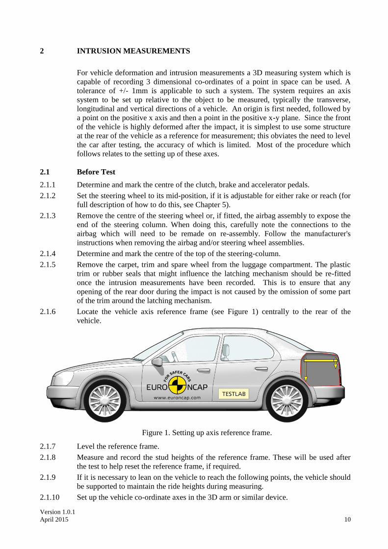
2.1.6 Locate the vehicle axis reference frame (see Figure 1) centrally to the rear of the
vehicle.
Figure 1. Setting up axis reference frame.
2.1.7 Level the reference frame.
2.1.8 Measure and record the stud heights of the reference frame. These will be used after
the test to help reset the reference frame, if required.
2.1.9 If it is necessary to lean on the vehicle to reach the following points, the vehicle should
be supported to maintain the ride heights during measuring.
2.1.10 Set up the vehicle co-ordinate axes in the 3D arm or similar device.
Version 1.0.1
April 2015 11
2.1.11 Mark and record the position of at least 5 datum points on the rear of the vehicle.
These points should be on structures which are not expected to be deformed in the test
and should be positioned such that they have wide spaced locations in three
dimensions and can all be reached with the 3D measuring system in one position.
2.1.12 Working on the passenger side of the vehicle determine and mark the positions on the
B-post which are:
a) at a distance of 100 mm above the sill.
b) at a distance of 100 mm beneath the lowest level of the side window aperture.
All points should be as close as possible to the rubber sealing strip around the door
aperture.
2.1.13 Measure and record the pre-impact positions of the two door aperture points.
2.1.14 Working on the driver’s side of the vehicle determine and mark the positions on the A
and B posts which are:
a) at a distance of 100 mm above the sill.
b) at a distance of 100 mm beneath the lowest level of the side window aperture.
All points should be as close as possible to the rubber sealing strip around the door
aperture.
2.1.15 Use the arm to measure the pre-impact positions of the centre of the top of the
steering-column and the four door aperture points.
2.1.16 Record the position of the centre of the un-depressed clutch, brake and accelerator
pedals and where applicable foot operated parking brake. If the pedal is adjustable, set
it to the mid position or a reasonable variation from this in accordance with the
manufacturer’s recommendations for the 5th percentile position.
2.1.17 Replace the steering wheel and airbag assembly. Check that all bolts are securely
fastened. Ensure that all connections to the airbag are replaced and check the
dashboard light to confirm the circuit is functional.
2.2 After Test
2.2.1 Before dummy removal measure the distance between all foot pedals and a fixed point
in the footwell, e.g. seat runner, seat mounting bolt. If access cannot be gained remove
the dummies, according to Section 7.4, taking care not to disturb any pedals and then
record the measurement. This measurement should be re-checked before the pedals
are measured with the 3D measuring system. If the pedal has moved re-position the
pedal using the measurement taken previously.
2.2.2 Remove the dummies according to Section 7.4 and remove the data acquisition and
emergency abort equipment (if fitted) from the luggage compartment.
2.2.3 Remove the centre of the steering wheel or airbag assembly.
2.2.4 Use any 3 of the 5 datum points at the rear of the vehicle, and their pre-impact
measurements, to redefine the measurement axes.
2.2.5 If the axes cannot be redefined from any 3 of the datum points relocate the axis
reference frame in the same position as in Section 2.1.6. Set the studs of the frame to
the same heights as in Section 2.1.8 (Figure 2). The frame should now be in the same
position relative to the car as it was before impact. Set up the measurement axes from
the frame.
2.2.6 Record the post-impact positions of the B-post points on the passenger’s side of the
vehicle.
Version 1.0.1
April 2015 12
2.2.7 Compare the vertical co-ordinate of the B-post sill point before and after the test.
2.2.8 Find the angle θ that best satisfies the following equation: z = - xsin θ + zcos θ for the
B-post sill point (where z = pre impact vertical measurement and x,z = post-impact
longitudinal and vertical).
2.2.9 Working on the passenger's side of the vehicle, record the post-impact co-ordinates of
the centre of the steering column, the centre of the clutch, brake and accelerator pedals,
and where applicable a foot operated parking brake, with no load applied to them and
in the blocked position (loaded with 200N to produce the maximum moment about the
pedal pivot), the door aperture points. Prior to the ‘blocked’ pedal measurement, i.e.
with the 200N applied, the brake fluid shall be removed to avoid the build-up of
hydraulic pressure. If the steering column has become detached during impact due to
the operation of the shear capsules, the column should be repositioned before
measurement in the upward and lateral directions so that it is in contact with whatever
structure(s) last constrained it from further movement. If any of the foot pedals become
detached do not take a measurement of that pedal.
2.2.10 Transform the post impact longitudinal and vertical measurements (x,z) using the
following equations.
z
x
-
θ =
Z
X
cossin
sincos
2.2.11 Where θ is the angle determined in Section 2.2.8. X and Z should now be in the same
frame of reference as the pre-impact measurements, assuming that the point on the
passenger’s side B-post sill is not displaced vertically or laterally during the impact.
2.2.12 From the pre-impact and adjusted post-impact data collected, determine
a) the longitudinal, lateral and vertical movement of the centre of the top of the
steering column.
b) the longitudinal and vertical movement of all of the foot operated pedals.
c) the rearward movement of the A-post at waist level.
d) the reduction in width of the door aperture at waist and sill levels.
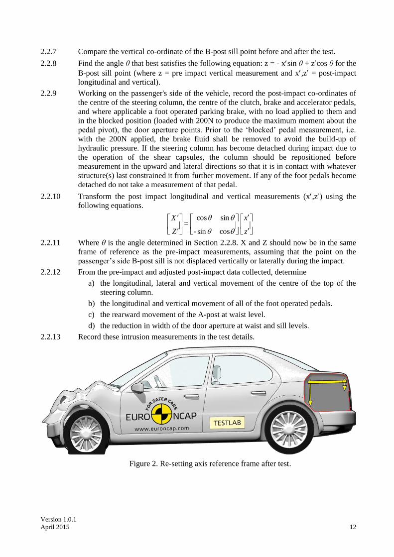
2.2.13 Record these intrusion measurements in the test details.
Figure 2. Re-setting axis reference frame after test.

Version 1.0.1
April 2015 13
3 DUMMY PREPARATION AND CERTIFICATION
3.1 General
Hybrid III 05F test dummies should be used for the front driver seat and the rear
passenger seat, at the opposite to the driver. They should conform to U.S. Department
of transportation, Code of Federal Regulations Part 572 Subpart O, except for
modifications and additions stated later. The parts of the dummy should be following
the latest agreed brand harmonised design:
Part Original manufacturer
Head Denton
Neck Denton
Upper Torso FTSS
Arms FTSS
Hands Denton
Lower Torso FTSS
Legs & Feet FTSS
3.2 Additions and Modifications to the Hybrid III Dummies
The additions and modifications which will change the dynamic behaviour of the test
dummies from Part 572 O specification dummies are:
3.2.1 Neoprene neck shields, with part number ABA-211-DN, must be fitted to the driver
and rear passenger.
3.2.2 The harmonized jacket, according to SAE J2921, must be fitted to the driver and rear
passenger.
3.2.3 The “Denton” lower leg cavity must be fitted to the driver and passenger.
3.3 Dummy Certification
Full details of the certification procedure for the Hybrid-III 05F dummy are available
elsewhere (see Part 572 Subpart O of US Department of Transportation Code of
Federal Regulations). No manufacturer shall have access to any pre-test information
regarding any of the test equipment to be used by Euro NCAP, or be permitted to
influence its selection in any way.
3.3.1 The Hybrid-III 05F dummies shall be re-certified after every THREE impact tests.
3.3.2 The chest shall be certified according to the frequency above and should meet both the
low speed thorax test as prescribed by SAE J2878, as well as the full certification test
detailed in CFR572. Additionally, chest potentiometer calibration and polynomial post
processing shall also be performed as detailed in SAE J2517.
3.3.3 If an injury criterion reaches or exceeds its normally accepted limit (eg. HIC15 of 700)
then that part of the dummy shall be re-certified.
3.3.4 If any part of a dummy is broken in a test then the part shall be replaced with a fully
certified component.
3.3.5 Copies of the dummy certification certificates will be provided as part of the full report
for a test.
Version 1.0.1
April 2015 14
3.4 Dummy Clothing and Footwear
3.4.1 Each dummy will be clothed with formfitting cotton stretch garments with short
sleeves and pants which should not cover the dummy’s knees.
3.4.2 Each dummy shall be fitted with shoes equivalent to those specified in MIL-S-21711E
(size 7½W).
3.5 Dummy Test Condition
3.5.1 Dummy Temperature
3.5.2 The dummy shall have a stabilised temperature in the range of 19ºC to 22ºC.
3.5.3 A stabilised temperature shall be obtained by soaking the dummy in temperatures that
are within the range specified above for at least 5 hours prior to the test.
3.5.4 Measure the temperature of the dummy using a recording electronic thermometer
placed inside the dummy’s thorax. The temperature should be recorded at intervals not
exceeding 10 minutes.
3.5.5 A printout of the temperature readings is to be supplied as part of the standard output
of the test.
3.5.6 Dummy Joints
3.5.7 All constant friction joints should have their ‘stiffness’ set by the following method:
3.5.8 Stabilise the dummy temperature by soaking in the required temperature range for at
least 5 hours.
3.5.9 The tensioning screw or bolt which acts on the constant friction surfaces should be
adjusted until the joint can just hold the adjoining limb in the horizontal. When a small
downward force is applied and then removed, the limb should continue to fall.
3.5.10 The dummy joints stiffness should be set as close as possible to the time of the test
and, in any case, not more than 24 hours before the test.
3.5.11 Maintain the dummy temperature within the range 19°C to 22°C between the time of
setting the limbs and up to a maximum of 10 minutes before the time of the test.
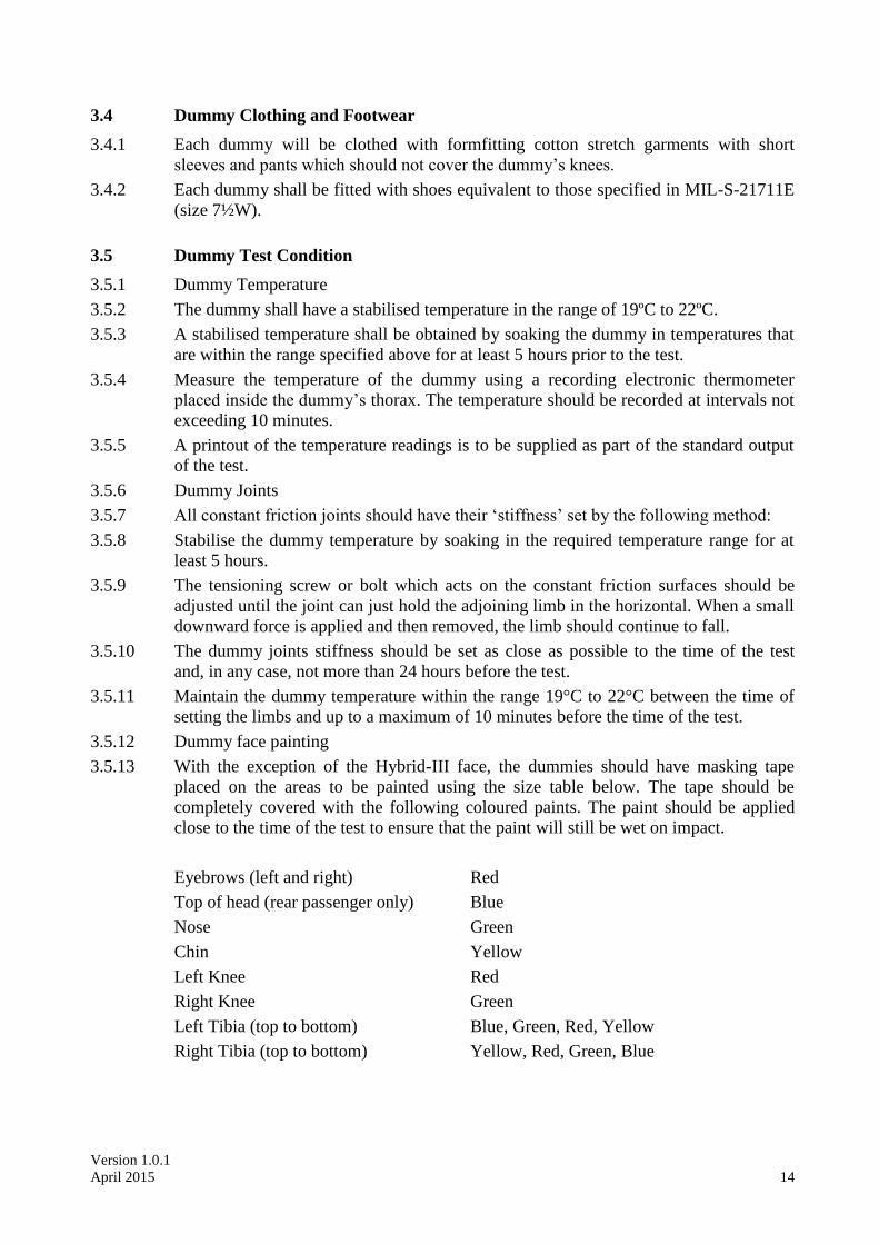
3.5.12 Dummy face painting
3.5.13 With the exception of the Hybrid-III face, the dummies should have masking tape
placed on the areas to be painted using the size table below. The tape should be
completely covered with the following coloured paints. The paint should be applied
close to the time of the test to ensure that the paint will still be wet on impact.
Eyebrows (left and right) Red
Top of head (rear passenger only) Blue
Nose Green
Chin Yellow
Left Knee Red
Right Knee Green
Left Tibia (top to bottom) Blue, Green, Red, Yellow
Right Tibia (top to bottom) Yellow, Red, Green, Blue
Version 1.0.1
April 2015 15
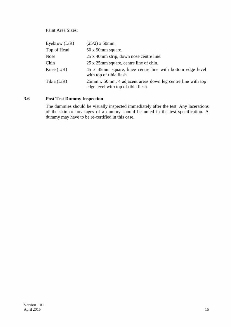
Paint Area Sizes:
Eyebrow (L/R) (25/2) x 50mm.
Top of Head 50 x 50mm square.
Nose 25 x 40mm strip, down nose centre line.
Chin 25 x 25mm square, centre line of chin.
Knee (L/R) 45 x 45mm square, knee centre line with bottom edge level
with top of tibia flesh.
Tibia (L/R) 25mm x 50mm, 4 adjacent areas down leg centre line with top
edge level with top of tibia flesh.
3.6 Post Test Dummy Inspection
The dummies should be visually inspected immediately after the test. Any lacerations
of the skin or breakages of a dummy should be noted in the test specification. A
dummy may have to be re-certified in this case.
Version 1.0.1
April 2015 16
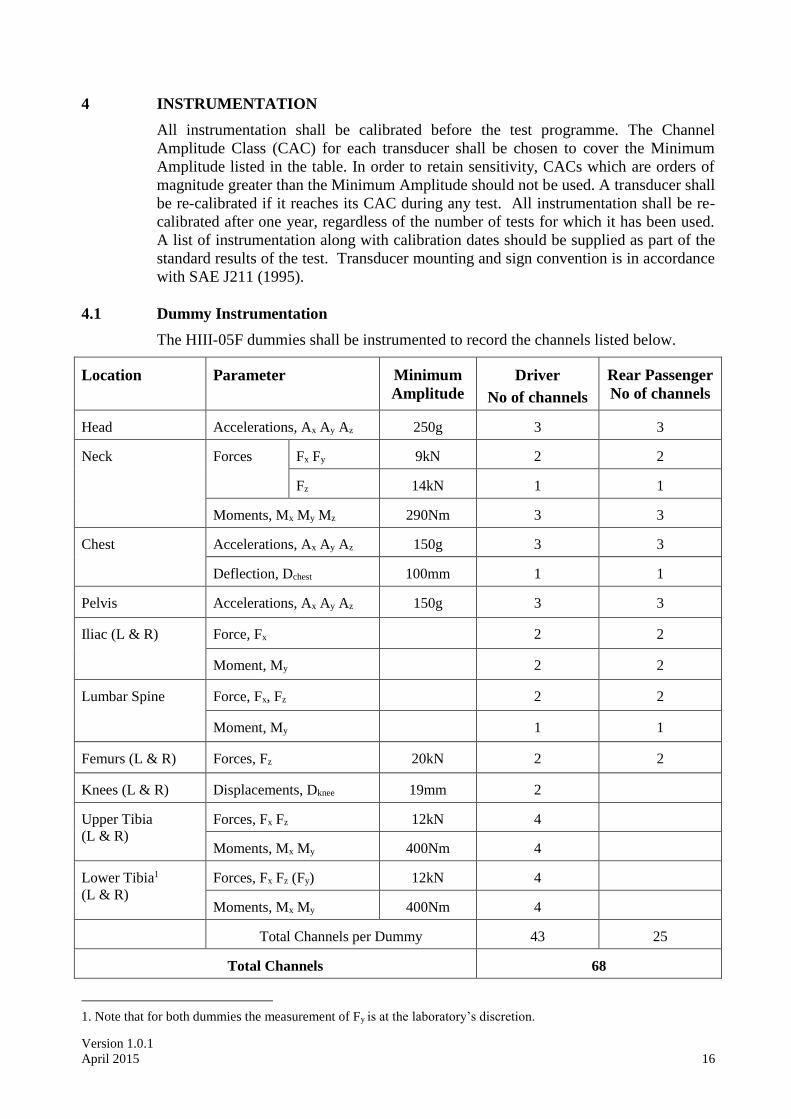
4 INSTRUMENTATION
All instrumentation shall be calibrated before the test programme. The Channel
Amplitude Class (CAC) for each transducer shall be chosen to cover the Minimum
Amplitude listed in the table. In order to retain sensitivity, CACs which are orders of
magnitude greater than the Minimum Amplitude should not be used. A transducer shall
be re-calibrated if it reaches its CAC during any test. All instrumentation shall be re-
calibrated after one year, regardless of the number of tests for which it has been used.
A list of instrumentation along with calibration dates should be supplied as part of the
standard results of the test. Transducer mounting and sign convention is in accordance
with SAE J211 (1995).
4.1 Dummy Instrumentation
The HIII-05F dummies shall be instrumented to record the channels listed below.
Location
Parameter
Minimum
Amplitude
Driver
No of channels
Rear Passenger
No of channels
Head
Accelerations, Ax Ay Az
250g
3
3
Neck
Forces
Fx Fy
9kN
2
2
Fz
14kN
1
1
Moments, Mx My Mz
290Nm
3
3
Chest
Accelerations, Ax Ay Az
150g
3
3
Deflection, Dchest
100mm
1
1
Pelvis
Accelerations, Ax Ay Az
150g
3
3
Iliac (L & R)
Force, Fx
2
2
Moment, My
2
2
Lumbar Spine
Force, Fx, Fz
2
2
Moment, My
1
1
Femurs (L & R)
Forces, Fz
20kN
2
2
Knees (L & R)
Displacements, Dknee
19mm
2
Upper Tibia
(L & R)
Forces, Fx Fz
12kN
4
Moments, Mx My
400Nm
4
Lower Tibia1
(L & R)
Forces, Fx Fz (Fy)
12kN
4
Moments, Mx My
400Nm
4
Total Channels per Dummy
43
25
Total Channels
68
1. Note that for both dummies the measurement of Fy is at the laboratory’s discretion.
Version 1.0.1
April 2015 17
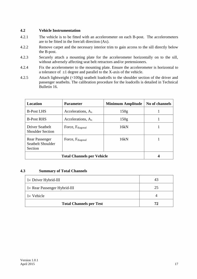
4.2 Vehicle Instrumentation
4.2.1 The vehicle is to be fitted with an accelerometer on each B-post. The accelerometers
are to be fitted in the fore/aft direction (Ax).
4.2.2 Remove carpet and the necessary interior trim to gain access to the sill directly below
the B-post.
4.2.3 Securely attach a mounting plate for the accelerometer horizontally on to the sill,
without adversely affecting seat belt retractors and/or pretensioners.
4.2.4 Fix the accelerometer to the mounting plate. Ensure the accelerometer is horizontal to
a tolerance of ±1 degree and parallel to the X-axis of the vehicle.
4.2.5 Attach lightweight (<100g) seatbelt loadcells to the shoulder section of the driver and
passenger seatbelts. The calibration procedure for the loadcells is detailed in Technical
Bulletin 16.
Location
Parameter
Minimum Amplitude
No of channels
B-Post LHS
Accelerations, Ax
150g
1
B-Post RHS
Accelerations, Ax
150g
1
Driver Seatbelt
Shoulder Section
Force, Fdiagonal
16kN
1
Rear Passenger
Seatbelt Shoulder
Section
Force, Fdiagonal
16kN
1
Total Channels per Vehicle
4
4.3 Summary of Total Channels
1 Driver Hybrid-III
43
1 Rear Passenger Hybrid-III
25
1 Vehicle
4
Total Channels per Test
72

Version 1.0.1
April 2015 18
5 PASSENGER COMPARTMENT ADJUSTMENTS
5.1 Driver Compartment Adjustments
Adjustment Required Setting Notes Methods
Seat Fore/Aft Initially Manufacturer's
5th percentile design
position
Permissible between fully
forward and 25% of travel,
measured in lowest
position.
Otherwise most forward.
Ensure feet
position
requirement
Seat Base Tilt Manufacturer's 5th
percentile design
position
Permissible up to mid
position, when in 5th
percentile for/aft position
Otherwise mid position
Seat Height Initially Manufacturer's
5th percentile design
position
Permissible between fully
upward and 75% travel
downwards, when in 5th
percentile for/aft position.
Otherwise mid position
Seat Back Angle Manufacturer's 5th
percentile design
position
Otherwise 23 to vertical,
as defined by Torso angle
Head Restraint Height Lowest position
Head Restraint Tilt
Manufacturer's 5th
percentile design
position
Otherwise mid position
Seat Lumbar Support Manufacturer's 5th
percentile design
position
Otherwise fully retracted
Arm-rests
(Front seats)
In-use position May be stowed if dummy
positioning does not allow
in-use position
Steering wheel -
vertical
Mid position
Steering wheel -
horizontal
Manufacturer's 5th
percentile design
position
Otherwise Mid position
with a minimum
horizontal distance to the
dummy of 250mm
measured from the centre
of the steering wheel*
Seat belt anchorage
(where adjustable)
Initially Manufacturer's
5th percentile design
position
If no design position then
set to lowest position
* When below 250mm, first adjust the steering forward. If not sufficient, move seat rearward to achieve the minimum
distance but ensure that the right foot maintains contact with the pedal as detailed in 6.4.8. The foot contact has a
higher priority.
Version 1.0.1
April 2015 19
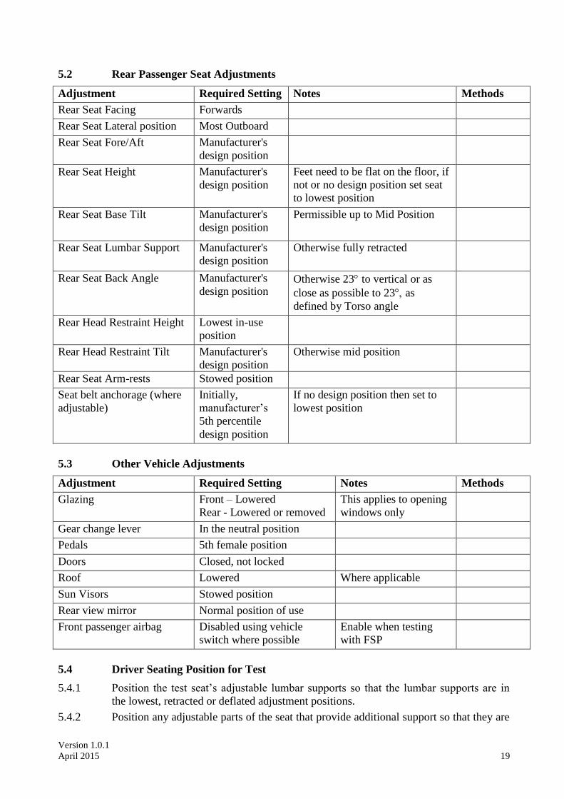
5.2 Rear Passenger Seat Adjustments
Adjustment Required Setting Notes Methods
Rear Seat Facing Forwards
Rear Seat Lateral position Most Outboard
Rear Seat Fore/Aft Manufacturer's
design position
Rear Seat Height Manufacturer's
design position
Feet need to be flat on the floor, if
not or no design position set seat
to lowest position
Rear Seat Base Tilt Manufacturer's
design position
Permissible up to Mid Position
Rear Seat Lumbar Support Manufacturer's
design position
Otherwise fully retracted
Rear Seat Back Angle Manufacturer's
design position Otherwise 23 to vertical or as
close as possible to 23as
defined by Torso angle
Rear Head Restraint Height Lowest in-use
position
Rear Head Restraint Tilt
Manufacturer's
design position
Otherwise mid position
Rear Seat Arm-rests Stowed position
Seat belt anchorage (where
adjustable)
Initially,
manufacturer’s
5th percentile
design position
If no design position then set to
lowest position
5.3 Other Vehicle Adjustments
Adjustment Required Setting Notes Methods
Glazing Front – Lowered
Rear - Lowered or removed
This applies to opening
windows only
Gear change lever In the neutral position
Pedals 5th female position
Doors Closed, not locked
Roof Lowered Where applicable
Sun Visors Stowed position
Rear view mirror Normal position of use
Front passenger airbag Disabled using vehicle
switch where possible
Enable when testing
with FSP
5.4 Driver Seating Position for Test
5.4.1 Position the test seat’s adjustable lumbar supports so that the lumbar supports are in
the lowest, retracted or deflated adjustment positions.
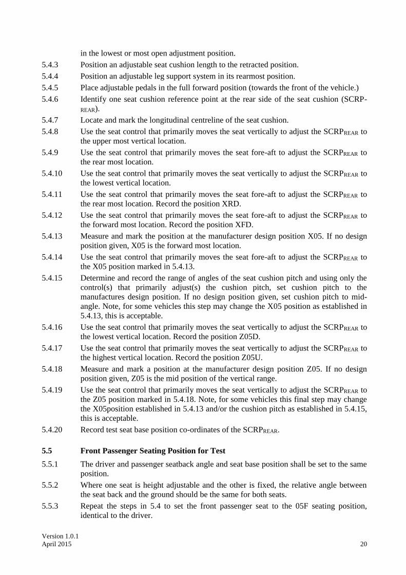
5.4.2 Position any adjustable parts of the seat that provide additional support so that they are
Version 1.0.1
April 2015 20
in the lowest or most open adjustment position.
5.4.3 Position an adjustable seat cushion length to the retracted position.
5.4.4 Position an adjustable leg support system in its rearmost position.
5.4.5 Place adjustable pedals in the full forward position (towards the front of the vehicle.)
5.4.6 Identify one seat cushion reference point at the rear side of the seat cushion (SCRP-
REAR).
5.4.7 Locate and mark the longitudinal centreline of the seat cushion.
5.4.8 Use the seat control that primarily moves the seat vertically to adjust the SCRPREAR to
the upper most vertical location.
5.4.9 Use the seat control that primarily moves the seat fore-aft to adjust the SCRPREAR to
the rear most location.
5.4.10 Use the seat control that primarily moves the seat vertically to adjust the SCRPREAR to
the lowest vertical location.
5.4.11 Use the seat control that primarily moves the seat fore-aft to adjust the SCRPREAR to
the rear most location. Record the position XRD.
5.4.12 Use the seat control that primarily moves the seat fore-aft to adjust the SCRPREAR to
the forward most location. Record the position XFD.
5.4.13 Measure and mark the position at the manufacturer design position X05. If no design
position given, X05 is the forward most location.
5.4.14 Use the seat control that primarily moves the seat fore-aft to adjust the SCRPREAR to
the X05 position marked in 5.4.13.
5.4.15 Determine and record the range of angles of the seat cushion pitch and using only the
control(s) that primarily adjust(s) the cushion pitch, set cushion pitch to the
manufactures design position. If no design position given, set cushion pitch to mid-
angle. Note, for some vehicles this step may change the X05 position as established in
5.4.13, this is acceptable.
5.4.16 Use the seat control that primarily moves the seat vertically to adjust the SCRPREAR to
the lowest vertical location. Record the position Z05D.
5.4.17 Use the seat control that primarily moves the seat vertically to adjust the SCRPREAR to
the highest vertical location. Record the position Z05U.
5.4.18 Measure and mark a position at the manufacturer design position Z05. If no design
position given, Z05 is the mid position of the vertical range.
5.4.19 Use the seat control that primarily moves the seat vertically to adjust the SCRPREAR to
the Z05 position marked in 5.4.18. Note, for some vehicles this final step may change
the X05position established in 5.4.13 and/or the cushion pitch as established in 5.4.15,
this is acceptable.
5.4.20 Record test seat base position co-ordinates of the SCRPREAR.
5.5 Front Passenger Seating Position for Test
5.5.1 The driver and passenger seatback angle and seat base position shall be set to the same
position.
5.5.2 Where one seat is height adjustable and the other is fixed, the relative angle between
the seat back and the ground should be the same for both seats.
5.5.3 Repeat the steps in 5.4 to set the front passenger seat to the 05F seating position,
identical to the driver.
Version 1.0.1
April 2015 21
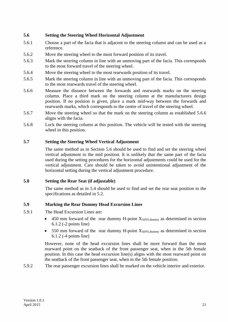
5.6 Setting the Steering Wheel Horizontal Adjustment
5.6.1 Choose a part of the facia that is adjacent to the steering column and can be used as a
reference.
5.6.2 Move the steering wheel to the most forward position of its travel.
5.6.3 Mark the steering column in line with an unmoving part of the facia. This corresponds
to the most forward travel of the steering wheel.
5.6.4 Move the steering wheel to the most rearwards position of its travel.
5.6.5 Mark the steering column in line with an unmoving part of the facia. This corresponds
to the most rearwards travel of the steering wheel.
5.6.6 Measure the distance between the forwards and rearwards marks on the steering
column. Place a third mark on the steering column at the manufacturers design
position. If no position is given, place a mark mid-way between the forwards and
rearwards marks, which corresponds to the centre of travel of the steering wheel.
5.6.7 Move the steering wheel so that the mark on the steering column as established 5.6.6
aligns with the facia.
5.6.8 Lock the steering column at this position. The vehicle will be tested with the steering
wheel in this position.
5.7 Setting the Steering Wheel Vertical Adjustment
The same method as in Section 5.6 should be used to find and set the steering wheel
vertical adjustment to the mid position. It is unlikely that the same part of the facia
used during the setting procedures for the horizontal adjustments could be used for the
vertical adjustment. Care should be taken to avoid unintentional adjustment of the
horizontal setting during the vertical adjustment procedure.
5.8 Setting the Rear Seat (if adjustable)
The same method as in 5.4 should be used to find and set the rear seat position to the
specifications as detailed in 5.2.
5.9 Marking the Rear Dummy Head Excursion Lines
5.9.1 The Head Excursion Lines are:
450 mm forward of the rear dummy H-point XAF05,dummy as determined in section
6.1.2 (-2 points line)
550 mm forward of the rear dummy H-point XAF05,dummy as determined in section
6.1.2 (-4 points line)
However, none of the head excursion lines shall be more forward than the most
rearward point on the seatback of the front passenger seat, when in the 5th female
position. In this case the head excursion line(s) aligns with the most rearward point on
the seatback of the front passenger seat, when in the 5th female position.
5.9.2 The rear passenger excursion lines shall be marked on the vehicle interior and exterior.
Version 1.0.1
April 2015 22
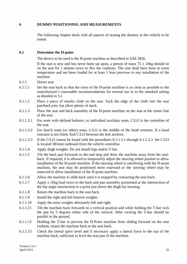
6 DUMMY POSITIONING AND MEASUREMENTS
The following chapter deals with all aspects of seating the dummy in the vehicle to be
tested.
6.1 Determine the H-point
The device to be used is the H-point machine as described in SAE J826.
If the seat is new and has never been sat upon, a person of mass 75 ± 10kg should sit
on the seat for 1 minute twice to flex the cushions. The seat shall have been at room
temperature and not been loaded for at least 1 hour previous to any installation of the
machine.
6.1.1 Driver seat
6.1.1.1 Set the seat back so that the torso of the H-point machine is as close as possible to the
manufacturer’s reasonable recommendations for normal use or to the standard setting
as detailed in 5.1
6.1.1.2 Place a piece of muslin cloth on the seat. Tuck the edge of the cloth into the seat
pan/back join, but allow plenty of slack.
6.1.1.3 Place the seat and back assembly of the H-point machine on the seat at the centre line
of the seat.
6.1.1.3.1 For seats with defined bolsters, or individual auxiliary seats, C/LO is the centreline of
the seat.
6.1.1.3.2 For bench seats (or other) seats, C/LO is the middle of the head restraint. If a head
restraint is not fitted, find C/LO between the belt anchors.
6.1.1.3.3 If the C/LO cannot be found with the procedures 6.1.1.3.1 through 6.1.1.3.3 the C/LO
is located 381mm outboard from the vehicle centreline.
6.1.1.4 Apply thigh weights. Do not install legs and/or T-bar.
6.1.1.5 Tilt the back pan forwards to the end stop and draw the machine away from the seat-
back. If required, it is allowed to temporarily adjust the steering wheel postion to allow
installation of the H-point machine. If the steering wheel is interfering with the H-point
machine, the seat may be positioned more rearward or the steering wheel may be
removed to allow installation of the H-point machine.
6.1.1.6 Allow the machine to slide back until it is stopped by contacting the seat back.
6.1.1.7 Apply a 10kg load twice to the back and pan assembly positioned at the intersection of
the hip angle intersection to a point just above the thigh bar housing.
6.1.1.8 Return the machine back to the seat back.
6.1.1.9 Install the right and left buttock weights.
6.1.1.10 Apply the torso weights alternately left and right.
6.1.1.11 Tilt the machine back forwards to a vertical position and while holding the T-bar rock
the pan by 5 degrees either side of the vertical. After rocking the T-bar should be
parallel to the ground.
6.1.1.12 Holding the T-bar to prevent the H-Point machine from sliding forward on the seat
cushion, return the machine back to the seat back.
6.1.1.13 Check the lateral spirit level and if necessary apply a lateral force to the top of the
machine back, sufficient to level the seat pan of the machine.
Version 1.0.1
April 2015 23
6.1.1.14 Adjust the seat back angle to the angle determined in 6.1.1.1, measured using the spirit
level and torso angle gauge of the H-point machine. Ensure that the torso remains in
contact with the seat back at all times. Ensure that the machine pan remains level at all
times.
6.1.1.15 Measure and record in the test details the position of the H-point relative to some
easily identifiable part of the vehicle structure
6.1.1.16 Measure and record in the test details the angle of the seat assembly of the H-point
machine and the position of the seat cushion front end
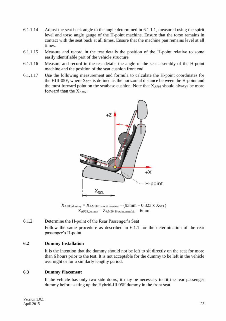
6.1.1.17 Use the following measurement and formula to calculate the H-point coordinates for
the HIII-05F, where XSCL is defined as the horizontal distance between the H-point and
the most forward point on the seatbase cushion. Note that XAF05 should always be more
forward than the XAM50.
XAF05,dummy = XAM50,H-point manikin + (93mm – 0.323 x XSCL)
ZAF05,dummy = ZAM50, H-point manikin – 6mm
6.1.2 Determine the H-point of the Rear Passenger’s Seat
Follow the same procedure as described in 6.1.1 for the determination of the rear
passenger’s H-point.
6.2 Dummy Installation
It is the intention that the dummy should not be left to sit directly on the seat for more
than 6 hours prior to the test. It is not acceptable for the dummy to be left in the vehicle
overnight or for a similarly lengthy period.
6.3 Dummy Placement
If the vehicle has only two side doors, it may be necessary to fit the rear passenger
dummy before setting up the Hybrid-III 05F dummy in the front seat.
Version 1.0.1
April 2015 24
6.3.1 Ensure that the seat is in the correct position as defined by Section 6.1.
6.3.2 Place the dummy in the seat with the torso against the seat back, the upper arms
against the seat back and the lower arms and hands against the outside of the upper leg.
6.4 Driver Dummy Positioning
Dummy positioning should be carried out immediately before the test and the vehicle
should not be moved or shaken thereafter until the test has begun. If a test run is
aborted and the vehicle brought to a standstill using an emergency braking method, the
dummy placement procedure should be repeated. If the dummy, after three attempts
cannot be positioned within the tolerances below then it is to be placed as close to the
tolerance limits as possible. Record this in the test details.
6.4.1 H-point
The dummy’s H-point shall be within 13mm in the vertical dimension and 13mm in
the horizontal dimension of the H-point as determined in Section 6.1. Record the
position of the dummy H-point in the test details.
6.4.2 Pelvic Angle
The pelvic angle measurement gauge should read 20 ± 2.5 from the horizontal.
Record the measured angle in the test details.
6.4.3 Head
The transverse instrumentation platform of the head shall be horizontal to within 2.5
Levelling of the head shall be carried out in this order:
Adjust the H-point within the limit
Adjust the pelvic angle within the limits
Adjust the neck bracket the minimum to ensure that the transverse
instrumentation platform is level within limits.
Record the measured angle in the test details.
6.4.4 Arms
The driver’s upper arms shall be adjacent to the torso as far as is possible
6.4.5 Hands
The driver dummy's hands shall have their palms placed against the steering wheel at a
position of a quarter to three. The thumbs should be lightly taped to the wheel.
6.4.6 Torso
The dummy's backs should be in contact with the seat back and the centre line of the
dummies should be lined up with the centre line of their respective seats.
6.4.7 Legs
The upper legs of the dummy shall be in contact with the seat cushion as far as
possible. The initial distance apart of the outside metal surfaces of the knees of each
dummy shall be 210mm ± 5mm. When the left foot is placed on a footrest or the right
foot is positioned onto the accelerator pedal as described in 6.4.8 below, the distance
between the knees may be altered. The legs of the dummies should be in vertical
longitudinal planes as far as is possible.
Version 1.0.1
April 2015 25
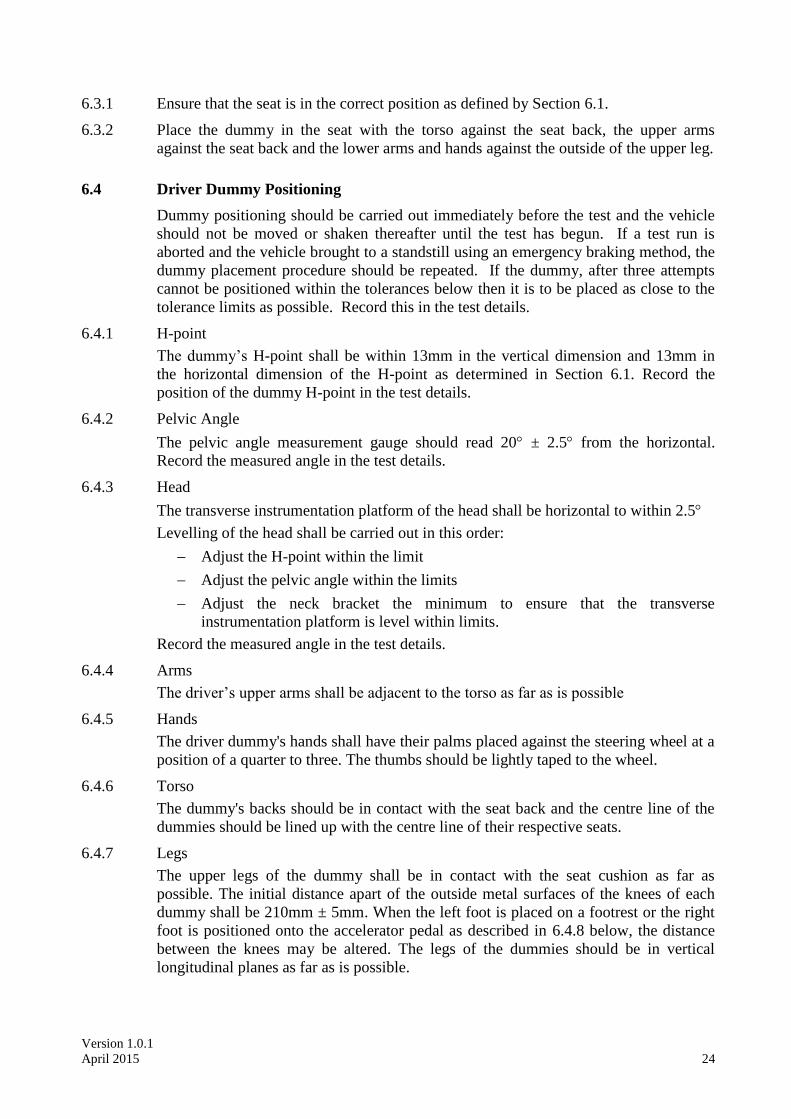
6.4.8 Feet
The driver dummy’s right foot shall be placed on the undepressed accelerator pedal
with the heel on the floor. The right foot should overlap the accelerator pedal with at
least 20mm.
When this is not the case and the seat is not in the foremost for/aft position, move the
seat forward until sufficient contact between right foot and accelerator pedal can be
achieved.
When it is not possible to achieve sufficient contact, follow the FMVSS 208 small
female seating positioning procedure, where a support block is used to ensure contact
with the pedal and floor.
If the right knee has been moved in order to place the right foot on the accelerator
pedal, move the left knee and foot an equal distance so that the legs are symmetrical.
The left foot should be placed as flat as possible on the toe-board parallel to the centre
line of the vehicle. If any part of the left foot is in contact with a foot-rest or wheel
arch when in this position then place the foot fully on this rest providing a normal
seating position can still be achieved. Keep the legs in the same vertical longitudinal
plane. The knee gap requirement may be ignored in this case. Note the final knee gap
in the test details.
6.4.9 Seat belt
6.4.9.1 Where possible, initially position the upper seat belt anchorage in the manufacturers
5th percentile design position. If no design position is provided, set the adjustable
upper seat belt anchorage to the lowest position.
6.4.9.2 Carefully place the seat belt across the dummy and lock as normal. It will be necessary
to re-position the hands as described in Section 6.4.5.
6.4.9.3 Remove the slack from the lap section of the webbing until it is resting gently around
the pelvis of the dummy. Only minimal force should be applied to the webbing when
removing the slack. The route of the lap belt should be as natural as possible.
6.4.9.4 Place one finger behind the diagonal section of the webbing at the height of the
dummy sternum. Pull the webbing away from the chest horizontally forward and allow
it to retract in the direction of the D-loop using only the force provided by the retractor
mechanism. Repeat this step three times, only.
6.4.9.5 After following the above steps, the seatbelt should lie in a natural position across the
dummy sternum assembly and shoulder clavicle. Where this is not the case, for
example the belt is close to or in contact with the neck shield or the belt is above the
shoulder rotation adjustment screw, and the upper belt anchorage is adjustable the
anchorage should be lowered and steps 6.4.9.3 and 6.4.9.4 repeated.
Version 1.0.1
April 2015 26
6.4.9.6 The upper anchorage should be lowered by a sufficient amount to ensure a natural belt
position following the repetition of steps 6.4.9.3 and 6.4.9.4 repeated. This may require
multiple attempts.
6.4.9.7 Once the belt is positioned the location of the belt should be marked across the dummy
chest to ensure that no further adjustments are made. Mark also the belt at the level of
the D-loop to be sure that the initial tension is maintained during test preparation.
6.4.9.8 Where the fitment of the shoulder belt loadcell significantly influences the natural
position of the belt, the loadcell may be supported from above with the use of a weak
non metallic wire or thread.
6.5 Rear Passenger Dummy Positioning
6.5.1 H-point
The dummy’s H-point shall be within 13mm in the vertical dimension and 13mm in
the horizontal dimension of the H-point as determined in Section 6.1.2. Record the
position of the dummy H-point in the test details.
6.5.2 Pelvic Angle
The pelvic angle measurement gauge should read 20 ± 2.5 from the horizontal.
Record the measured angle in the test details. If pelvic angle cannot be achieved, use
the design torso angle as a reference value.
6.5.3 Head
The transverse instrumentation platform of the head shall be horizontal to within 2.5
Levelling of the head shall be carried out in this order:
Adjust the H-point within the limit
Adjust the pelvic angle within the limits
Adjust the neck bracket the minimum to ensure that the transverse
instrumentation platform is level within limits
Record the measured angle in the test details.
6.5.4 Upper limbs
The upper arms shall be positioned in contact with the seatback. The forearms and the
hands shall be positioned as close as possible to the outer sides of the thighs while the
little fingers are lightly in contact with the seat cushion. If there is interference by trim
or other interior parts, the interfered upper limb shall be placed on the armrest of the
same side to avoid any interference.
6.5.5 Torso
The dummy's backs should be in contact with the seat back and the centre line of the
dummies should be lined up with the centre line of their respective seats.
6.5.6 Lower limbs
The upper legs of the dummy shall be in contact with the seat cushion as far as
possible. The distance apart of the outside metal surfaces of the knees of each dummy
shall be 210mm ± 5mm. The legs of the dummies should be in vertical longitudinal
planes as far as is possible.
Version 1.0.1
April 2015 27
The legs shall be positioned as distant as possible from the front end of the rear seat
cushion while the thighs are kept in contact with the seat cushion.
Each leg shall be lowered until the foot comes in contact with the floor while the foot
and tibia are kept in a right angle to one another and the thigh inclination angle kept
constant. When each heel is in contact with the floor, the foot shall be rotated so that
the toe comes as much in contact as possible with the floor.
If it is not possible to have each foot in contact with the floor, the foot shall be lowered
until the calf comes in contact with the front end of the seat cushion or the back of the
foot comes in contact with the vehicle interior. The foot shall be kept as parallel as
possible to the floor.
In case of interference by front seat anchorages or by a vehicle body protrusion, the
foot shall be rotated as minimally as possible around the tibia. In case interference still
remains, the femur shall be rotated to resolve or minimize the interference. The foot
shall be moved inward or outward while the separation distance between the knees is
kept constant.
In case of significant interference by the front seat in its test position or by a vehicle
body protrusion, the leg shall be moved toward the occupant side by lifting and
keeping the thigh as much in contact as possible with the rear seat cushion.
6.5.7 Finalization of torso position and readjustment of foot position (if any)
After manipulation of the lower limbs according to 6.5.6, the dummy position has to be
reconfirmed in accordance with the prescriptions in 6.5.1 (H point), 6.5.2 (pelvic
angle) and 6.5.3 (head angle). Any foot displacement during the final positioning of
the torso should be undone.
6.5.8 Seat belt
6.5.8.1 Where possible, initially position the upper seat belt anchorage in the manufacturers
5th percentile design position. If no design position is provided, set the adjustable
upper seat belt anchorage to the lowest position.
6.5.8.2 Carefully place the seat belt across the dummy and lock as normal. It will be necessary
to re-position the upper limbs as described in Section 6.5.4
6.5.8.3 Remove the slack from the lap section of the webbing until it is resting gently around
the pelvis of the dummy. Only minimal force should be applied to the webbing when
removing the slack. The route of the lap belt should be as natural as possible.
6.5.8.4 Place one finger behind the diagonal section of the webbing at the height of the
dummy sternum. Pull the webbing away from the chest horizontally forward and allow
it to retract in the direction of the D-loop using only the force provided by the retractor
mechanism. Repeat this step three times, only.
6.5.8.5 After following the above steps, the seatbelt should lie in a natural position across the
dummy sternum assembly and shoulder clavicle. Where this is not the case, for
example the belt is close to or in contact with the neck shield or the belt is above the
shoulder rotation adjustment screw, and the upper belt anchorage is adjustable the
anchorage should be lowered and steps 6.5.8.3 and 6.5.8.4 repeated.
6.5.8.6 The upper anchorage should be lowered by a sufficient amount to ensure a natural belt
position following the repetition of steps 6.5.8.3 and 6.5.8.4 repeated. This may require
multiple attempts.
6.5.8.7 Where the fitment of the shoulder belt loadcell significantly influences the natural
Version 1.0.1
April 2015 28
position of the belt, the loadcell may be supported from above with the use of a weak
non metallic wire or thread.
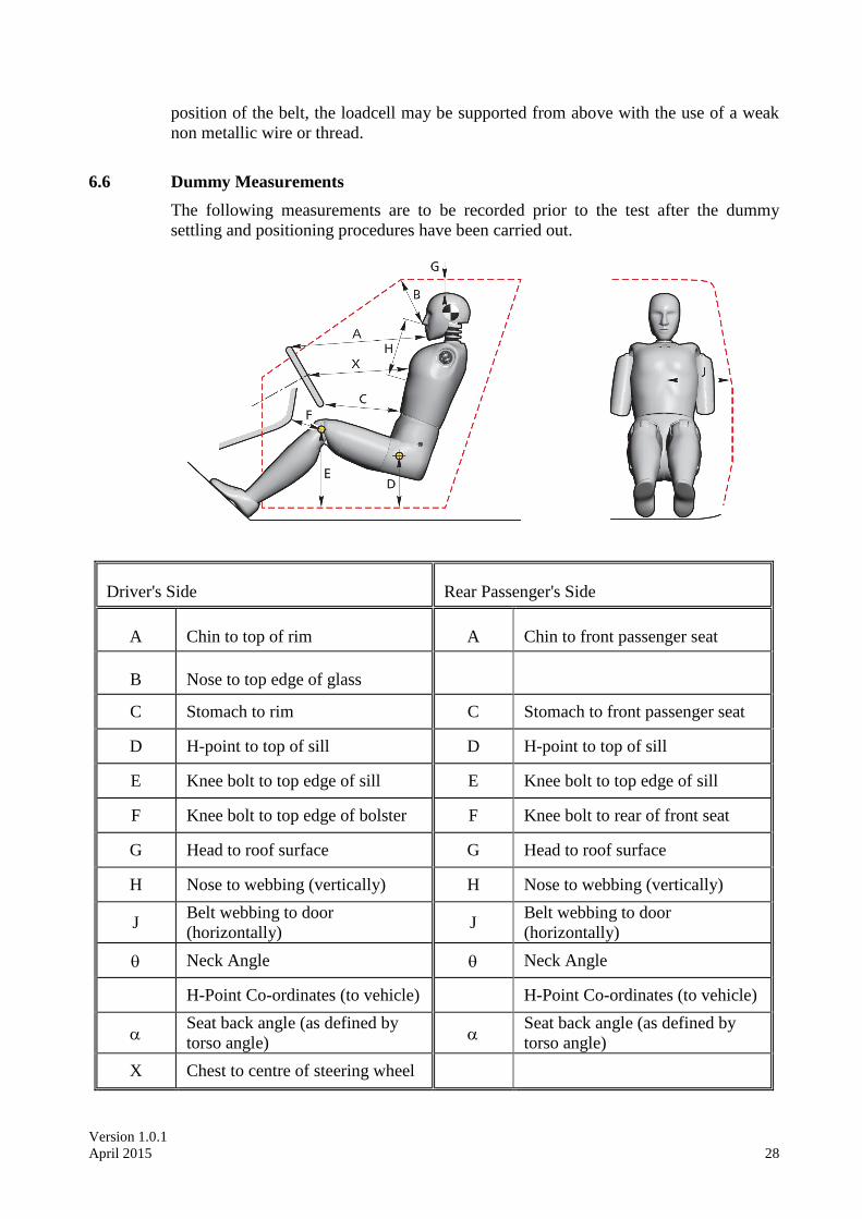
6.6 Dummy Measurements
The following measurements are to be recorded prior to the test after the dummy
settling and positioning procedures have been carried out.
Driver's Side Rear Passenger's Side
A Chin to top of rim A Chin to front passenger seat
B Nose to top edge of glass
C Stomach to rim C Stomach to front passenger seat
D H-point to top of sill D H-point to top of sill
E Knee bolt to top edge of sill E Knee bolt to top edge of sill
F Knee bolt to top edge of bolster F Knee bolt to rear of front seat
G Head to roof surface G Head to roof surface
H Nose to webbing (vertically) H Nose to webbing (vertically)
J Belt webbing to door
(horizontally) J
Belt webbing to door
(horizontally)
Neck Angle Neck Angle
H-Point Co-ordinates (to vehicle) H-Point Co-ordinates (to vehicle)
Seat back angle (as defined by
torso angle)
Seat back angle (as defined by
torso angle)
X Chest to centre of steering wheel
Version 1.0.1
April 2015 29
7 TEST PARAMETERS
An on-board data acquisition unit will be used. This equipment will be triggered by a
contact plate at the point of first contact (t=0) and will record digital information at a
sample rate of 20kHz (alternatively a sample rate of 10kHz may be used). The
equipment conforms to SAE J211.
BEFORE THE TEST, ENSURE THAT THE LIVE BATTERY IS CONNECTED, A
SINGLE KEY IS IN THE IGNITION, THE IGNITION IS ON AND THAT THE
AIRBAG LIGHT ON THE DASHBOARD ILLUMINATES AS NORMAL (WHERE
FITTED)
If the vehicle is fitted with a brake pedal retraction mechanism which requires a
vacuum present in the brake system, the engine may be run for a predetermined time,
specified by the manufacturer.
7.1 Barrier
The barrier shall consist of a block of reinforced concrete not less than 3 m wide in
front and not less than 1.5 m high. The barrier shall be of such thickness that it weighs
at least 70 metric tons. The front face shall be flat, vertical and perpendicular to the
axis of the run-up track. It shall be covered with plywood boards 20 ± 2 mm thick, in
good condition.
If available install a high resolution loadcell wall (LCW) to the concrete block, with
the plywood in front of the LCW. The height of this LCW should be 80mm ± 2mm
from the ground.
7.2 Speed
7.2.1 Measure the speed of the vehicle as near as possible to the point of impact.
7.2.2 This speed should be 50km/h ± 1km/h. Record the actual test speed in the test details.
TARGET SPEED = 50km/h ± 1km/h
7.3 Door Opening Force
7.3.1 Check that none of the doors have locked during the test
7.3.2 Try to open each of the doors (front doors followed by rear doors) using a spring-pull
attached to the external handle. The opening force should be applied perpendicular to
the door, in a horizontal plane, unless this is not possible. The manufacturer may
specify a reasonable variation in the angle of the applied force. Gradually increase the
force on the spring-pull, up to a maximum of 500N, until the door unlatches. If the
door does not open record this then try to unlatch the door using the internal handle.
Again attempt to open the door using the spring-pull attached to the external handle.
Record the forces required to unlatch the door and to open it to 45o in the test details.
7.3.3 If a door does not open with a force of 500N then try the adjacent door on the same
side of the vehicle. If this door then opens normally, retry the first door.
7.3.4 If the door still does not open, record in the test details whether the door could be
opened using extreme hand force or if tools were needed.
Version 1.0.1
April 2015 30
In the event that sliding doors are fitted, the force required to open the door
sufficiently enough for an adult to escape should be recorded in place of the
45o opening force.
7.4 Dummy Removal
7.4.1 Do not move the seats. Try to remove the dummies.
7.4.2 If the dummies cannot be removed with the seats in their original positions, recline the
seat back and try again. Note any entrapment of the dummy.
7.4.3 If the dummies can still not be removed, try to slide the seats back on their runners.
7.4.4 If the dummies can still not be moved, the seats can be cut out of the car.
7.4.5 Record the method used to remove the dummies.
7.5 Intrusion Measurements
Take the vehicle intrusion measurements. See Section 2.2 for a full description of how
to do this.