Embed Size (px)
Citation preview
PROTOCOL PERFORMANCE MEASUREMENT METHODOLOGY -
EXPERIMENTATION WITH SIGNALING SYSTEM NO 7
by
ANAND TUMKUR & AVIJIT DUTTA
[email protected] & [email protected]
A THESIS
Submitted in partial fulfillment of the requirements for the degree
MASTER OF SOFTWARE ENGINEERING
School of Innovation, Design and Engineering MÄLARDALEN UNIVERSITY
Västerås, Sweden
1st June 2009
Approved by:
Academic Supervisor: Daniel Flemström Ericsson Mentor: Pär Asplund
Examiner: Mats Björkman
Abstract
Performance is the driving force for the effective network utilization in the current
telecommunication world. The thesis aims to define suitable performance measurement
methodologies for communication over stack based Signalling System No 7 (SS7). This thesis
also throws a quick glance on open source SS7 and Ericsson proprietary SS7 protocols, to devise
performance measurement approach that can be adopted to develop sophisticated tools. We
adopt a scientific experimental approach for numerical measurement of throughput and latency
of the protocol stack. Our current work finishes experimentation with open source SS7 protocol
(SCTP) in Fedora based two identical servers. SCTP (Stream Control Transmission Protocol) is
an important transport layer protocol for communication of SS7 message over an IP network.
Message communication using SCTP protocol over an IP/Ethernet network between these two
identical servers has been measured and analyzed using the IPerf tool. TCP (Transmission
Control Protocol) being another important transport layer protocol of TCP/IP stack, the
performance of TCP is compared with SCTP. The results prove that under normal circumstances
TCP gains over SCTP and our analysis support that under multi homing support, SCTP should
gain over TCP when throughput is measured.
1
Table of Contents
List of Figures ................................................................................................................................. 3
List of Tables................................................................................................................................... 5
Acknowledgements ......................................................................................................................... 6
1. Introduction ............................................................................................................................. 7
1.1. Outline................................................................................................................................. 7
1.2. Prerequisite Knowledge ...................................................................................................... 7
2. Background ............................................................................................................................. 8
2.1. Telecommunication Mobile Network ................................................................................. 8
2.2. CPP Platform..................................................................................................................... 10
2.2.1. CPP Platform for 3G mobile network........................................................................... 10
2.3. Signaling System No 7...................................................................................................... 13
2.3.1. Open Signaling System No 7 ........................................................................................ 13
2.3.2. SS7 over IP.................................................................................................................... 14
2.3.3. Analogy of Open SS7 and CPP SS7 ............................................................................. 17
3. Related Work......................................................................................................................... 19
3.1. Literature review methodology ......................................................................................... 19
3.2. Performance Measurement of SS7/Intelligent Network. .................................................. 20
3.2.1. Measurement Approach ................................................................................................ 21
3.3. Methods for Communicating SS7 Messages over a Packet-Based Network Using a TALI
22
3.3.1. Measurement Approach ................................................................................................ 23
3.4. Performance Evaluation of the Stream Control Transmission Protocol ........................... 24
3.5. Performance Analysis of CCSN, based on SS#7 .............................................................. 27
3.6. Application Protocols and Performance Benchmarks....................................................... 29
3.7. Processing and measuring SS7 message signal units (MSU’s)......................................... 31
3.8. Tele-traffic simulator with SS7 for circuit switched and intelligent network................... 33
3.9. Tools on SS7 Performance Analysis:................................................................................ 34
4. Protocol Performance Measurement Methodology............................................................... 36
2
4.1. Complete Stack Measurement........................................................................................... 36
4.2. Stack Layer Measurement................................................................................................. 37
5. An Experimental Approach to Measure Performance .......................................................... 39
5.1. Experimentation ................................................................................................................ 39
5.2. IPerf Performance Measurement Tool .............................................................................. 40
5.3. Results ............................................................................................................................... 42
5.4. Analysis ............................................................................................................................. 44
6. Summary and Conclusion ..................................................................................................... 48
7. Future Work .......................................................................................................................... 48
Appendix A - Acronyms ............................................................................................................... 52
Appendix B - Open SS7 Installation and Troubleshooting........................................................... 54
Release Packages ...................................................................................................................... 54
Operating systems ..................................................................................................................... 54
System requirements ................................................................................................................. 54
Package dependencies............................................................................................................... 55
Installation Process.................................................................................................................... 57
Appendix C - IPerf Commands..................................................................................................... 58
Appendix D - NetPerf Commands ................................................................................................ 60
3
List of Figures
Figure 2.1-1: Structure of GSM network (key elements) [11]....................................................... 9
Figure 2.2-1: Horizontal and Vertical Network Architecture [18]............................................... 10
Figure 2.2.1-1: CPP Structural Units within a Node [18] ............................................................ 12
Figure 2.2.1-2: SS7 communication between two nodes in telecom work [13] .......................... 13
Figure 2.3.1-1: Simple SS7 Protocol Stack [9] ............................................................................ 14
Figure 2.3.2-1: Adaptation for SS7 over IP ................................................................................. 15
Figure 2.3.2-2: SCTP advantage over TCP [10] .......................................................................... 16
Figure 2.3.2-3: SS7 over IP [10] .................................................................................................. 17
Figure 2.3.3-1: Cello Signaling and transport services [14] ........................................................ 17
Figure 3.1-1: Study Selection Process ......................................................................................... 20
Figure 3.2-1: Sample CCSN (Common Channel Signaling system) physical network [15] [16]21
Figure 3.2.1-1: Performance measurement methodology ............................................................ 22
Figure 3.3-1: TALI layer controls SS7 over TCP/IP network [17].............................................. 23
Figure 3.3.1-1: Round-trip time calculation using TALI layer [17] ............................................ 24
Figure 3.4-1: SCTP Test Bed Architecture [1] ............................................................................ 25
Figure 3.4-2: Mean Signaling Message Transimission Delay Over IP Network [1] ................... 26
Figure 3.5-1: CCSN (Common Channel Signaling system) physical network [3] ...................... 28
Figure 3.5-2: Call Scenario in Basic ISDN Calls [3] ................................................................... 28
Figure 3.6-1: RPC, Bulk_get and Conn_disc time [9] ................................................................. 30
Figure 3.7-1: CDR processing architecture [22] .......................................................................... 32
Figure 3.8-1: Hybrid network architecture [23] ........................................................................... 33
Figure 4.1-1: Performance measurement approach...................................................................... 36
Figure 4.2-1: SS7 stack performance measurement methodology............................................... 38
Figure 5.1-1: Experimental Setup for Performance Measurement .............................................. 40
Figure 5.2-1: IPerf server ............................................................................................................. 41
Figure 5.2-2: IPerf Client ............................................................................................................. 42
Figure 5.3-1: Throughput Comparison of SCTP and TCP........................................................... 44
4
Figure 5.4-1: Multi Homing Support in SCTP............................................................................. 45
Figure 5.4-2: SCTP Server Response at Different Message Length............................................ 46
Figure 5.4-3: SCTP Client initiation at Different Message Length ............................................. 47
5
List of Tables
Table 1: Research Paper Selection ................................................................................................ 19
Table 2: Environmental Factors during Measurement - 1............................................................. 26
Table 3: Environmental Factors during Measurement - 2............................................................. 29
Table 4: Environmental Factors during Measurement - 3............................................................. 30
Table 5: Open Source Tools for SS7 Performance Analysis ........................................................ 34
Table 6: Commercial Tools for SS7 Performance Analysis ......................................................... 35
Table 7: SCTP Performance.......................................................................................................... 42
Table 8: TCP Performance............................................................................................................ 43
Table 9: IPerf CLI Options............................................................................................................ 58
Table 10: NetPerf CLI Options ..................................................................................................... 61

6
Acknowledgements
This dissertation could not have been written without Daniel Flemström who not only guided as
our supervisor but provided the inspiration and force to excel better than ever before. We are
grateful to TATA Consultancy Services (TCS), India, Ericsson AB, Sweden and Mälardalen
University, Sweden for providing this wonderful opportunity. We are deeply thankful to Prof.
Mats Björkman for all his valuable feedback and support throughout the thesis. Thanks to Pär
Apslund, Ericsson for helping us to narrow down and focus intensely on core aspect of our
thesis. We appreciate Brian Bidulock (Open SS7 community) for extending their help as and
when required. Thanks to Malin Rosqvist for helping us with proofreading of our manuscript.
Last but not the least, we wish to thank our TCS student group at Mälardalen university for
patiently listening to our thesis status presentation every week and providing valuable feedback.
7
1. Introduction
This is a D-level Master Thesis report in Software Engineering at the School of Innovation,
Design and Engineering at Mälardalen University, Sweden. The thesis is carried out at Industrial
Research and Innovation Lab (IRIL) provided by the university with immense support from
Ericsson AB, Älvsjö, Sweden. The academic supervisor is Daniel Flemström and industrial
supervisor is Pär Asplund. This thesis has been written during 20 weeks from January 2009 to
June 2009. The report aims at providing the reader with background knowledge of
communication protocols in telecommunication systems and the new measurement approaches &
aspects of performance.
1.1. Outline
The report is organized to give the reader a brief introduction to the basics in telecommunication
and communication protocol in Section 2. Section 3 highlights the related work carried out
previously in the field of experimentation with protocol performance measurement in a
controlled environment. Section 4 deals with our proposal for protocol measurement of the
entire SS7 measurement and individual protocol layer measurement. Section 5 is the result and
analysis of our experimentation with Open source signaling system #7 protocol stack. Summary
and conclusion is represented in Section 6 with future work in Section 7. Appendix A provides
the list of acronyms used in the document. Appendix B provides Open SS7 installation and
trouble shooting. Appendix C and Appendix D provides the command lines interface options of
IPerf and NetPerf protocol performance measurement tools respectively.
1.2. Prerequisite Knowledge
The reader is not expected to have in-depth knowledge in the telecom domain as the initial
chapter provides a brief introduction to the GSM mobile network. The basics of computer
communication network will be help to understand signaling system #7 protocol stack. The
experiment is carried out in a Linux environment and hence to repeat the experiment, the reader
is required to know user basic skills of the Linux operating system.
8
2. Background
This section is intended to provide an overview of the telecommunication system.
Telecommunication nodes (sub systems) are built on platforms which support various node
applications. CPP (Connectivity Packet Platform) is an Ericsson proprietary platform of their
telecommunication sub-systems. Signaling System # 7 is a core protocol stack used for internode
communication in telecom system.
2.1. Telecommunication Mobile #etwork
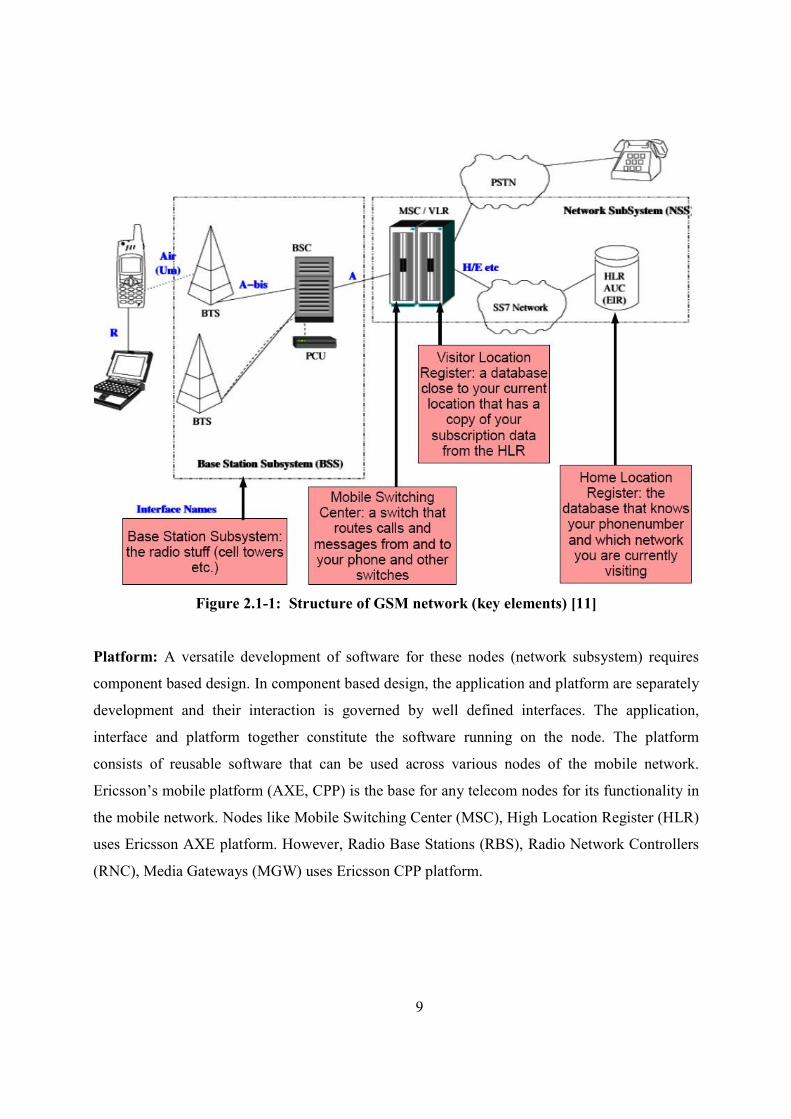
Figure 2.1-1 is a simple mobile network, depicted for easy understanding of the proceeding
sections. Each element like BTS (Base Transceiver Station), MSC (Mobile Switching Center),
HLR (Home Location Register) are called nodes in a mobile network. BTS is the telecom node
that connects the wireless mobile devices with the network. The wireless devices can be a mobile
handset (GSM & CDMA), WLL (Wireless local loop), VOIP devices (Voice over internet
protocol). The main component of network sub system is Mobile Switching Center (MSC) which
provides normal switching functionality for PSTN (Public Switched Telephone Network) and
ISDN (Integrated Switch Digital Networks). For mobile users, MSC provide additional
functionality like registration, authentication and call location. Home Location Register (HLR) is
the database to register all mobile users and usually there is one HLR per network. Each mobile
SIM card issued is recorded in HLR using a primary key called IMSI (International Mobile
Subscriber Identity).
For voice calls or data access using mobile phones, base station subsystem takes care of radio
communication via over-the-air interface. Once the mobile enters the BTS region, the BTS
updates the VLR/HLR database. When the user makes a call, a call setup request is sent the
nearest mobile network via BTS. Within the network, MSC checks with VLR to authenticate
whether the user has sufficient credits and other records. After authentication, MSC sets up the
call using global PSTN network if the call is towards a landline.
9
Figure 2.1-1: Structure of GSM network (key elements) [11]
Platform: A versatile development of software for these nodes (network subsystem) requires
component based design. In component based design, the application and platform are separately
development and their interaction is governed by well defined interfaces. The application,
interface and platform together constitute the software running on the node. The platform
consists of reusable software that can be used across various nodes of the mobile network.
Ericsson’s mobile platform (AXE, CPP) is the base for any telecom nodes for its functionality in
the mobile network. Nodes like Mobile Switching Center (MSC), High Location Register (HLR)
uses Ericsson AXE platform. However, Radio Base Stations (RBS), Radio Network Controllers
(RNC), Media Gateways (MGW) uses Ericsson CPP platform.
10
2.2. CPP Platform
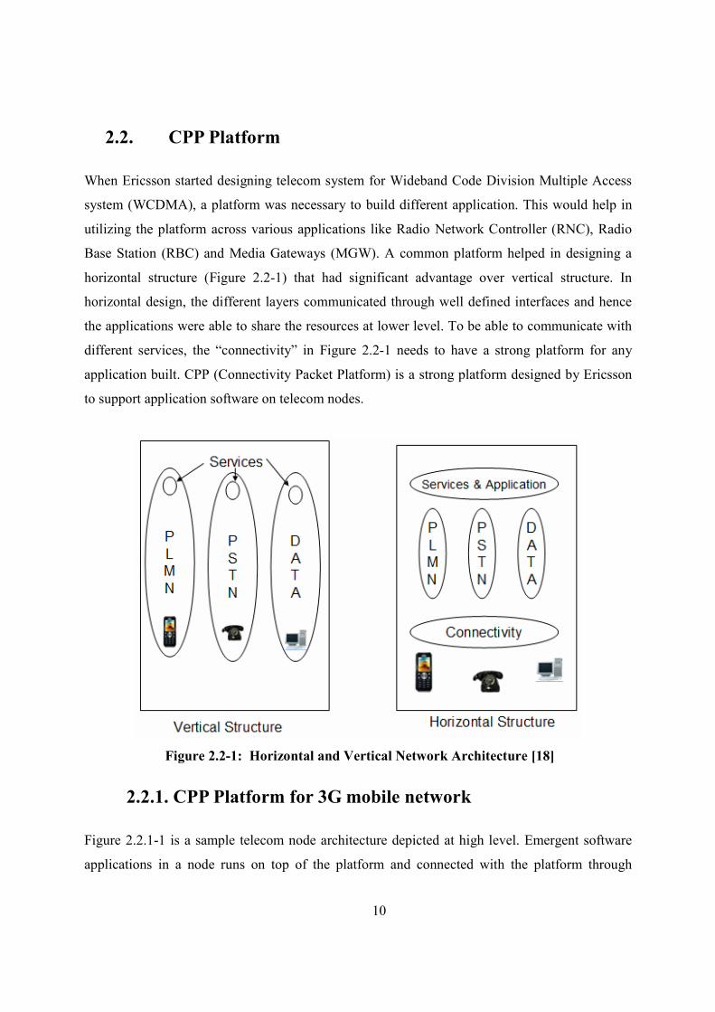
When Ericsson started designing telecom system for Wideband Code Division Multiple Access
system (WCDMA), a platform was necessary to build different application. This would help in
utilizing the platform across various applications like Radio Network Controller (RNC), Radio
Base Station (RBC) and Media Gateways (MGW). A common platform helped in designing a
horizontal structure (Figure 2.2-1) that had significant advantage over vertical structure. In
horizontal design, the different layers communicated through well defined interfaces and hence
the applications were able to share the resources at lower level. To be able to communicate with
different services, the “connectivity” in Figure 2.2-1 needs to have a strong platform for any
application built. CPP (Connectivity Packet Platform) is a strong platform designed by Ericsson
to support application software on telecom nodes.
Figure 2.2-1: Horizontal and Vertical #etwork Architecture [18]
2.2.1. CPP Platform for 3G mobile network
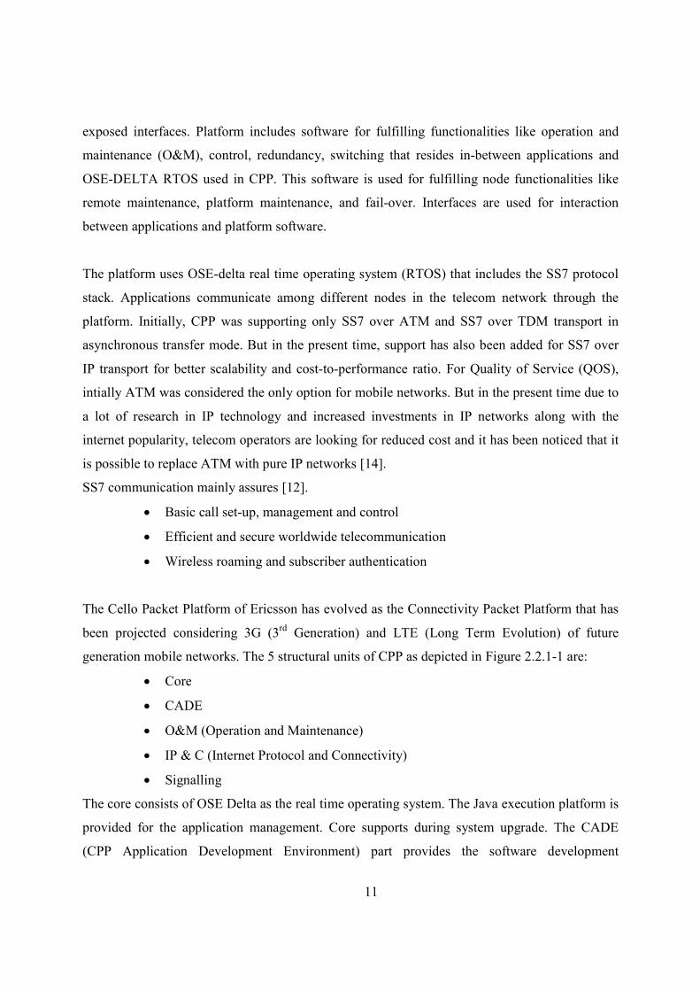
Figure 2.2.1-1 is a sample telecom node architecture depicted at high level. Emergent software
applications in a node runs on top of the platform and connected with the platform through
11
exposed interfaces. Platform includes software for fulfilling functionalities like operation and
maintenance (O&M), control, redundancy, switching that resides in-between applications and
OSE-DELTA RTOS used in CPP. This software is used for fulfilling node functionalities like
remote maintenance, platform maintenance, and fail-over. Interfaces are used for interaction
between applications and platform software.
The platform uses OSE-delta real time operating system (RTOS) that includes the SS7 protocol
stack. Applications communicate among different nodes in the telecom network through the
platform. Initially, CPP was supporting only SS7 over ATM and SS7 over TDM transport in
asynchronous transfer mode. But in the present time, support has also been added for SS7 over
IP transport for better scalability and cost-to-performance ratio. For Quality of Service (QOS),
intially ATM was considered the only option for mobile networks. But in the present time due to
a lot of research in IP technology and increased investments in IP networks along with the
internet popularity, telecom operators are looking for reduced cost and it has been noticed that it
is possible to replace ATM with pure IP networks [14].
SS7 communication mainly assures [12].
• Basic call set-up, management and control
• Efficient and secure worldwide telecommunication
• Wireless roaming and subscriber authentication
The Cello Packet Platform of Ericsson has evolved as the Connectivity Packet Platform that has
been projected considering 3G (3rd Generation) and LTE (Long Term Evolution) of future
generation mobile networks. The 5 structural units of CPP as depicted in Figure 2.2.1-1 are:
• Core
• CADE
• O&M (Operation and Maintenance)
• IP & C (Internet Protocol and Connectivity)
• Signalling
The core consists of OSE Delta as the real time operating system. The Java execution platform is
provided for the application management. Core supports during system upgrade. The CADE
(CPP Application Development Environment) part provides the software development
12
environment for both application software and CPP software. CADE helps in debugging and
building load modules. IP & Connectivity provides the services of transporting over the ATM
and IP networks and network synchronization. The Operation and Maintenance part of a Cello
based node provides the management of services, interface support and application support. The
signaling System Area provides the service for sending the signaling messages between the
nodes in a network.
Figure 2.2.1-1: CPP Structural Units within a #ode [18]
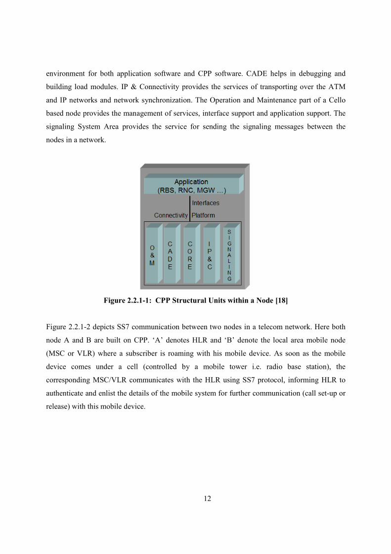
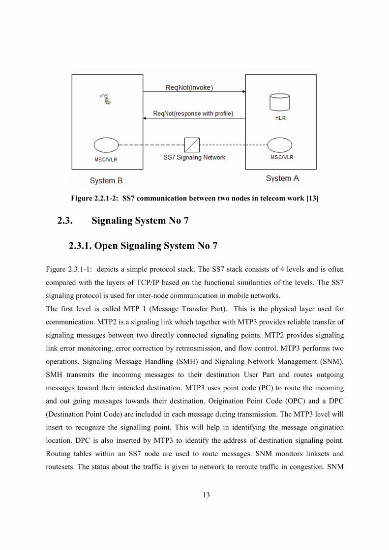
Figure 2.2.1-2 depicts SS7 communication between two nodes in a telecom network. Here both
node A and B are built on CPP. ‘A’ denotes HLR and ‘B’ denote the local area mobile node
(MSC or VLR) where a subscriber is roaming with his mobile device. As soon as the mobile
device comes under a cell (controlled by a mobile tower i.e. radio base station), the
corresponding MSC/VLR communicates with the HLR using SS7 protocol, informing HLR to
authenticate and enlist the details of the mobile system for further communication (call set-up or
release) with this mobile device.
13
Figure 2.2.1-2: SS7 communication between two nodes in telecom work [13]
2.3. Signaling System #o 7
2.3.1. Open Signaling System #o 7
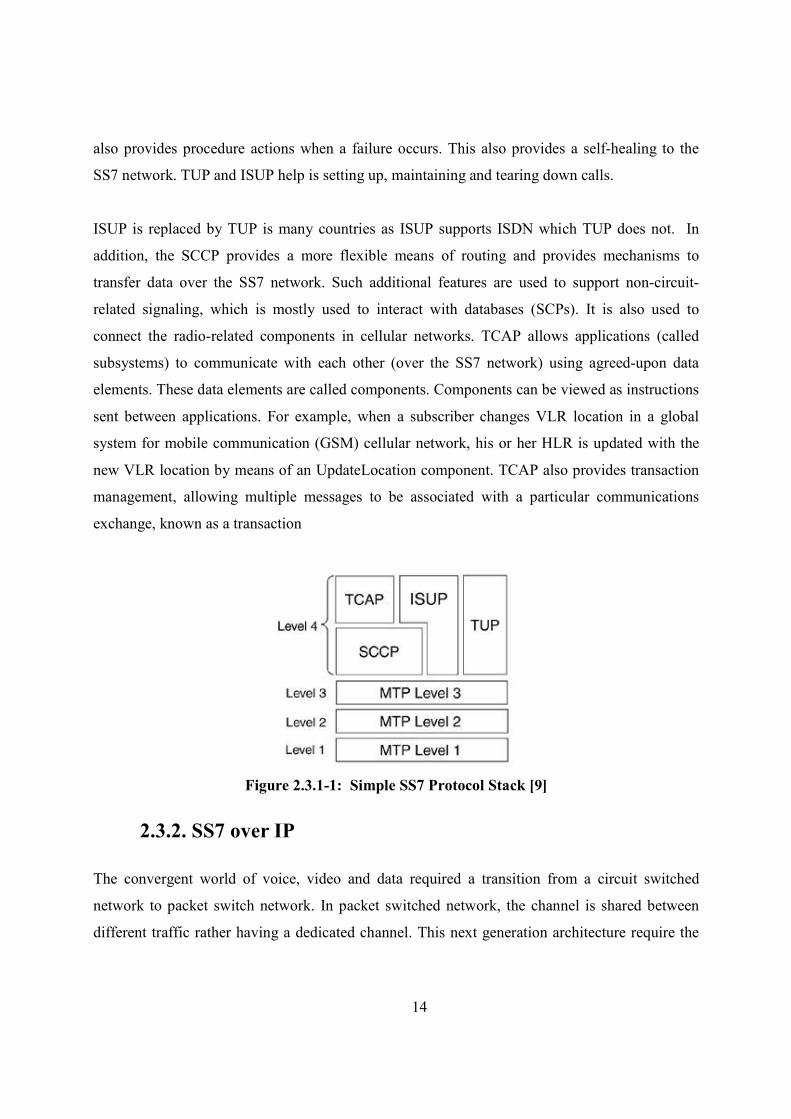
Figure 2.3.1-1: depicts a simple protocol stack. The SS7 stack consists of 4 levels and is often
compared with the layers of TCP/IP based on the functional similarities of the levels. The SS7
signaling protocol is used for inter-node communication in mobile networks.
The first level is called MTP 1 (Message Transfer Part). This is the physical layer used for
communication. MTP2 is a signaling link which together with MTP3 provides reliable transfer of
signaling messages between two directly connected signaling points. MTP2 provides signaling
link error monitoring, error correction by retransmission, and flow control. MTP3 performs two
operations, Signaling Message Handling (SMH) and Signaling Network Management (SNM).
SMH transmits the incoming messages to their destination User Part and routes outgoing
messages toward their intended destination. MTP3 uses point code (PC) to route the incoming
and out going messages towards their destination. Origination Point Code (OPC) and a DPC
(Destination Point Code) are included in each message during transmission. The MTP3 level will
insert to recognize the signalling point. This will help in identifying the message origination
location. DPC is also inserted by MTP3 to identify the address of destination signaling point.
Routing tables within an SS7 node are used to route messages. SNM monitors linksets and
routesets. The status about the traffic is given to network to reroute traffic in congestion. SNM
14
also provides procedure actions when a failure occurs. This also provides a self-healing to the
SS7 network. TUP and ISUP help is setting up, maintaining and tearing down calls.
ISUP is replaced by TUP is many countries as ISUP supports ISDN which TUP does not. In
addition, the SCCP provides a more flexible means of routing and provides mechanisms to
transfer data over the SS7 network. Such additional features are used to support non-circuit-
related signaling, which is mostly used to interact with databases (SCPs). It is also used to
connect the radio-related components in cellular networks. TCAP allows applications (called
subsystems) to communicate with each other (over the SS7 network) using agreed-upon data
elements. These data elements are called components. Components can be viewed as instructions
sent between applications. For example, when a subscriber changes VLR location in a global
system for mobile communication (GSM) cellular network, his or her HLR is updated with the
new VLR location by means of an UpdateLocation component. TCAP also provides transaction
management, allowing multiple messages to be associated with a particular communications
exchange, known as a transaction
Figure 2.3.1-1: Simple SS7 Protocol Stack [9]
2.3.2. SS7 over IP
The convergent world of voice, video and data required a transition from a circuit switched
network to packet switch network. In packet switched network, the channel is shared between
different traffic rather having a dedicated channel. This next generation architecture require the
15
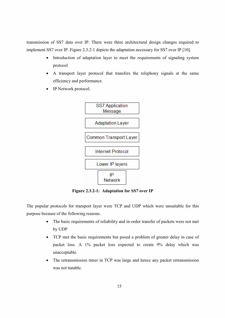
transmission of SS7 data over IP. There were three architectural design changes required to
implement SS7 over IP. Figure 2.3.2-1 depicts the adaptation necessary for SS7 over IP [10].
• Introduction of adaptation layer to meet the requirements of signaling system
protocol
• A transport layer protocol that transfers the telephony signals at the same
efficiency and performance.
• IP Network protocol.
Figure 2.3.2-1: Adaptation for SS7 over IP
The popular protocols for transport layer were TCP and UDP which were unsuitable for this
purpose because of the following reasons.
• The basic requirements of reliability and in-order transfer of packets were not met
by UDP
• TCP met the basic requirements but posed a problem of greater delay in case of
packet loss. A 1% packet loss expected to create 9% delay which was
unacceptable.
• The retransmission timer in TCP was large and hence any packet retransmission
was not tunable.
16
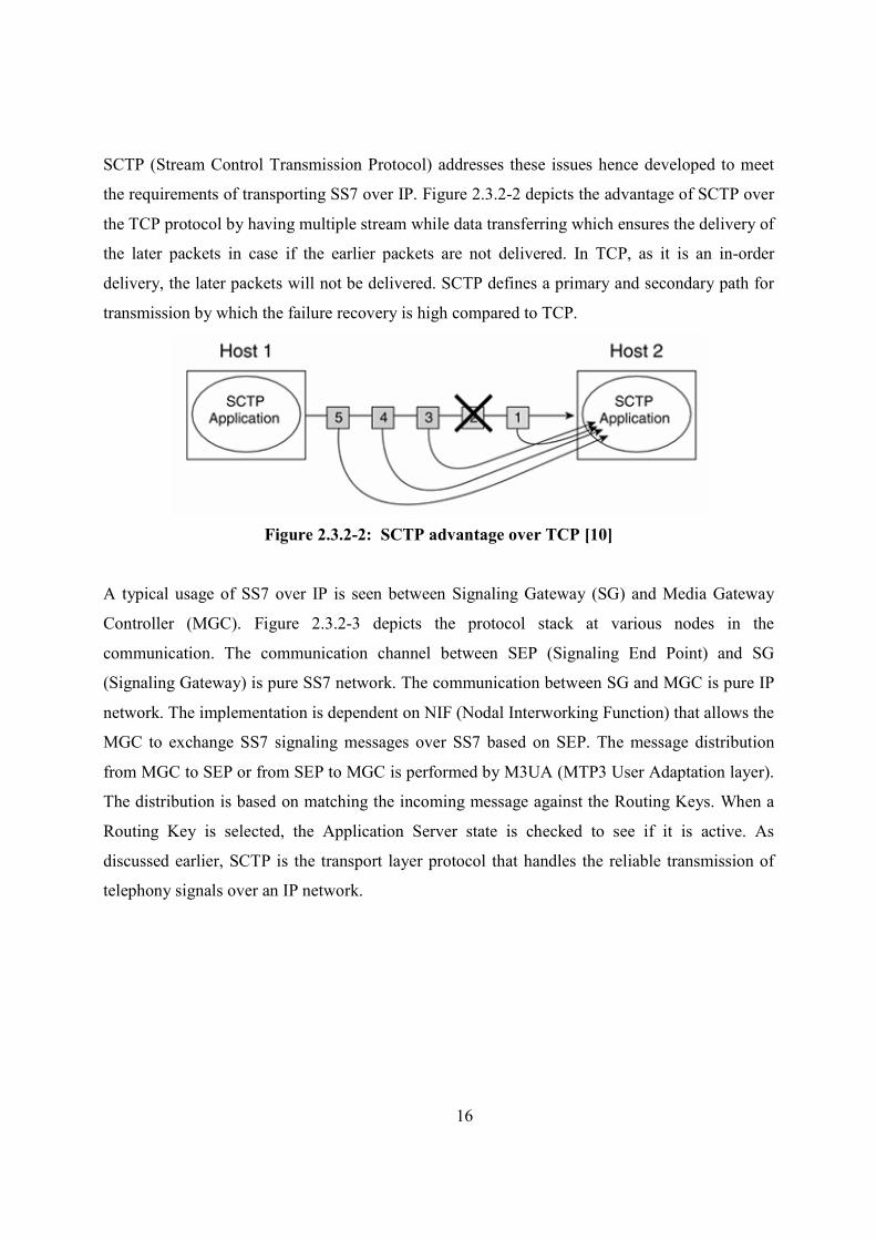
SCTP (Stream Control Transmission Protocol) addresses these issues hence developed to meet
the requirements of transporting SS7 over IP. Figure 2.3.2-2 depicts the advantage of SCTP over
the TCP protocol by having multiple stream while data transferring which ensures the delivery of
the later packets in case if the earlier packets are not delivered. In TCP, as it is an in-order
delivery, the later packets will not be delivered. SCTP defines a primary and secondary path for
transmission by which the failure recovery is high compared to TCP.
Figure 2.3.2-2: SCTP advantage over TCP [10]
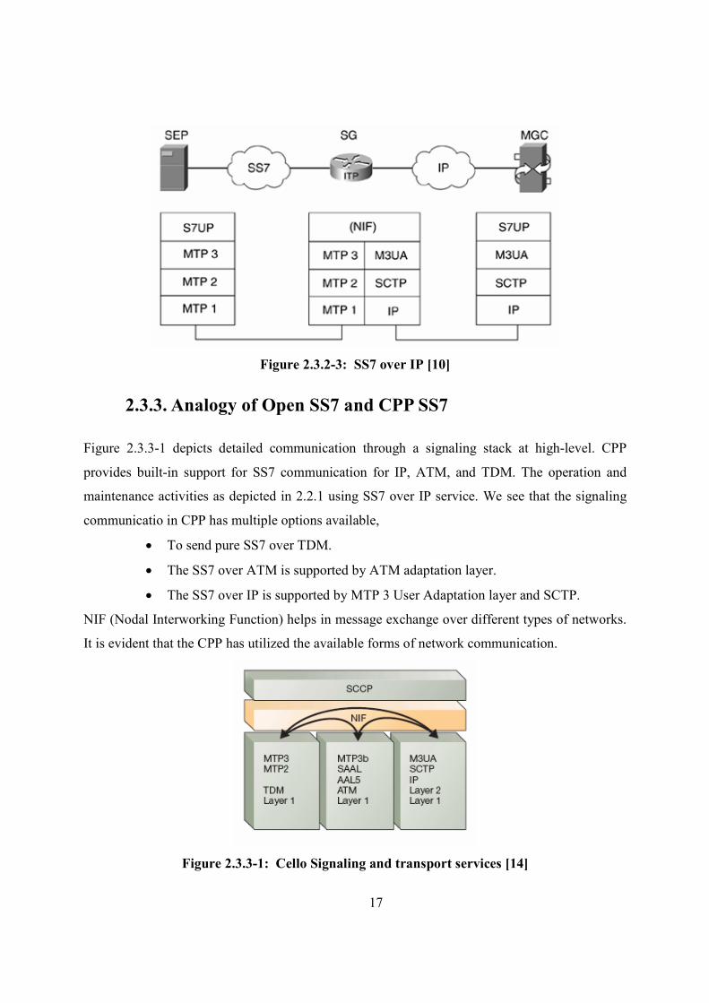
A typical usage of SS7 over IP is seen between Signaling Gateway (SG) and Media Gateway
Controller (MGC). Figure 2.3.2-3 depicts the protocol stack at various nodes in the
communication. The communication channel between SEP (Signaling End Point) and SG
(Signaling Gateway) is pure SS7 network. The communication between SG and MGC is pure IP
network. The implementation is dependent on NIF (Nodal Interworking Function) that allows the
MGC to exchange SS7 signaling messages over SS7 based on SEP. The message distribution
from MGC to SEP or from SEP to MGC is performed by M3UA (MTP3 User Adaptation layer).
The distribution is based on matching the incoming message against the Routing Keys. When a
Routing Key is selected, the Application Server state is checked to see if it is active. As
discussed earlier, SCTP is the transport layer protocol that handles the reliable transmission of
telephony signals over an IP network.
17
Figure 2.3.2-3: SS7 over IP [10]
2.3.3. Analogy of Open SS7 and CPP SS7
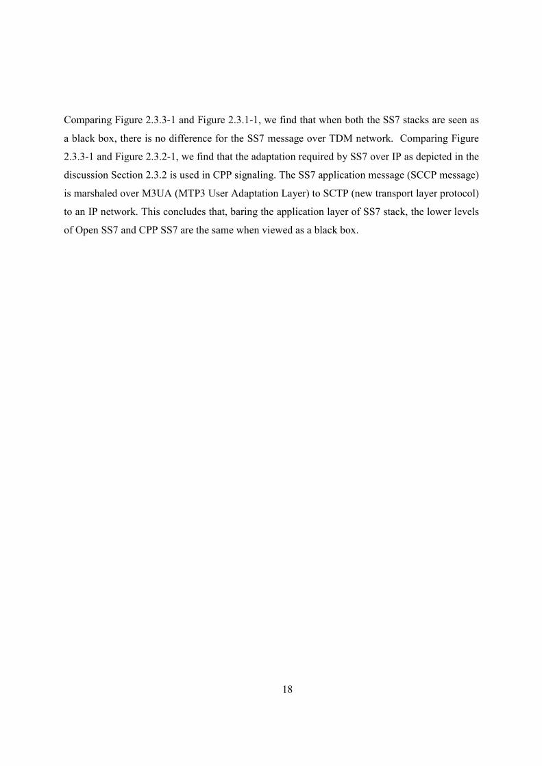
Figure 2.3.3-1 depicts detailed communication through a signaling stack at high-level. CPP
provides built-in support for SS7 communication for IP, ATM, and TDM. The operation and
maintenance activities as depicted in 2.2.1 using SS7 over IP service. We see that the signaling
communicatio in CPP has multiple options available,
• To send pure SS7 over TDM.
• The SS7 over ATM is supported by ATM adaptation layer.
• The SS7 over IP is supported by MTP 3 User Adaptation layer and SCTP.
NIF (Nodal Interworking Function) helps in message exchange over different types of networks.
It is evident that the CPP has utilized the available forms of network communication.
Figure 2.3.3-1: Cello Signaling and transport services [14]
18
Comparing Figure 2.3.3-1 and Figure 2.3.1-1, we find that when both the SS7 stacks are seen as
a black box, there is no difference for the SS7 message over TDM network. Comparing Figure
2.3.3-1 and Figure 2.3.2-1, we find that the adaptation required by SS7 over IP as depicted in the
discussion Section 2.3.2 is used in CPP signaling. The SS7 application message (SCCP message)
is marshaled over M3UA (MTP3 User Adaptation Layer) to SCTP (new transport layer protocol)
to an IP network. This concludes that, baring the application layer of SS7 stack, the lower levels
of Open SS7 and CPP SS7 are the same when viewed as a black box.
19
3. Related Work
3.1. Literature review methodology
A broad and systematic search in the following databases was performed to obtain credible
information.
• ACM Digital Library (<portal.acm.org>)
• IEEE eXplore (<ieeexplore.ieee.org>)
The keywords used for searching were generic to a cover broad area of the database. “Network
performance measurement”, “protocol measurement “signaling system performance”,
“Signaling system 7”, “SS7 in mobile network” the keywords were used.
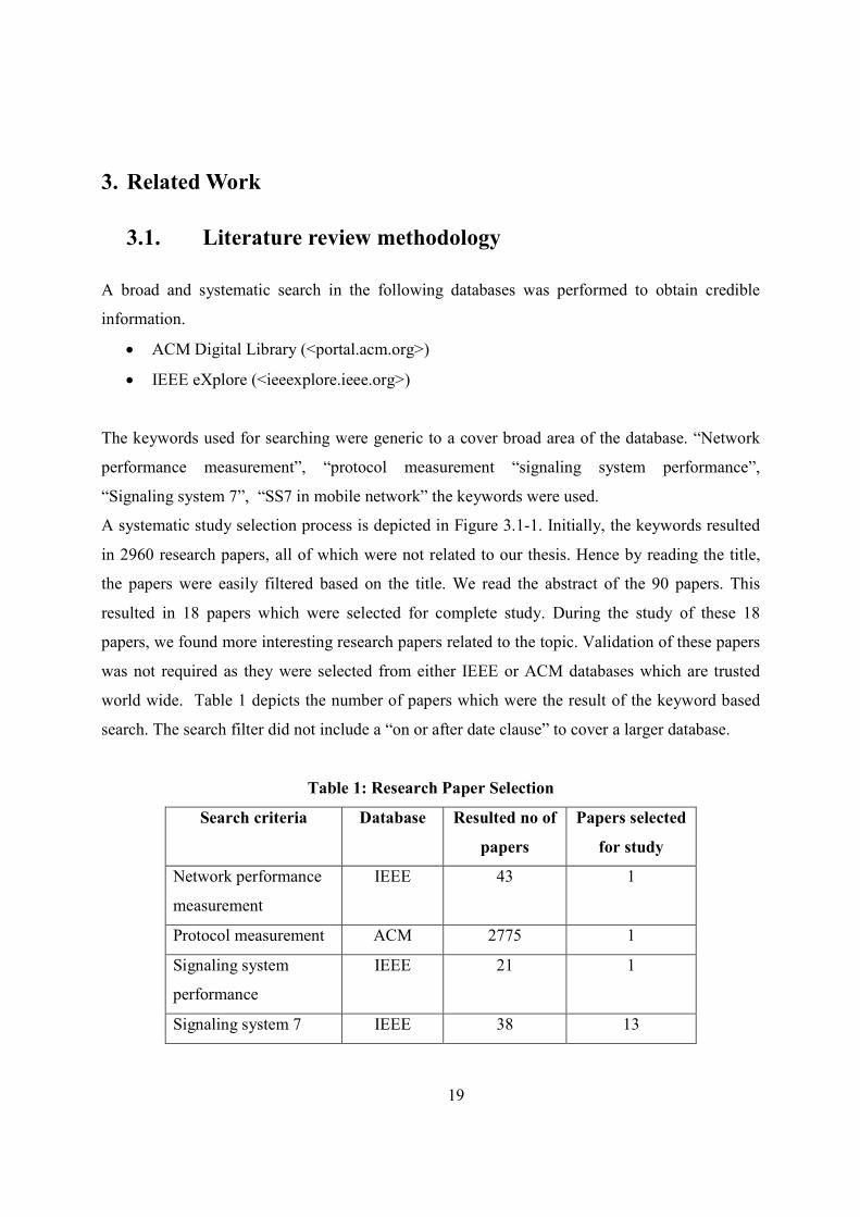
A systematic study selection process is depicted in Figure 3.1-1. Initially, the keywords resulted
in 2960 research papers, all of which were not related to our thesis. Hence by reading the title,
the papers were easily filtered based on the title. We read the abstract of the 90 papers. This
resulted in 18 papers which were selected for complete study. During the study of these 18
papers, we found more interesting research papers related to the topic. Validation of these papers
was not required as they were selected from either IEEE or ACM databases which are trusted
world wide. Table 1 depicts the number of papers which were the result of the keyword based
search. The search filter did not include a “on or after date clause” to cover a larger database.
Table 1: Research Paper Selection
Search criteria Database Resulted no of
papers
Papers selected
for study
Network performance
measurement
IEEE 43 1
Protocol measurement ACM 2775 1
Signaling system
performance
IEEE 21 1
Signaling system 7 IEEE 38 13
20
Search criteria Database Resulted no of
papers
Papers selected
for study
SS7 in mobile network ACM 83 2
Figure 3.1-1: Study Selection Process
3.2. Performance Measurement of SS7/Intelligent #etwork.
SS7 is the commonly used protocol for voice call set-up in the telecom industry. Even IN
(Intelligent Network) systems are being proposed to include SS7 communication instead of X.25
network due to various constraints [15]. The essence of this protocol can be visualized by “A
case in point being the recent CSP network failures caused by computer executing the SS7 in the
East and West coasts and to the ATST (January, 1990) network which suffered a wide-spread
SS7 related outage caused by timing interactions between recovery programs in its Intelligent
*etwork (I*)” [15]. Author delineates that the SS7 network failure can be severe and lead to
whole network (mainly prepaid mobile services) failure.
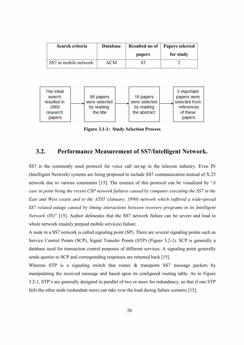
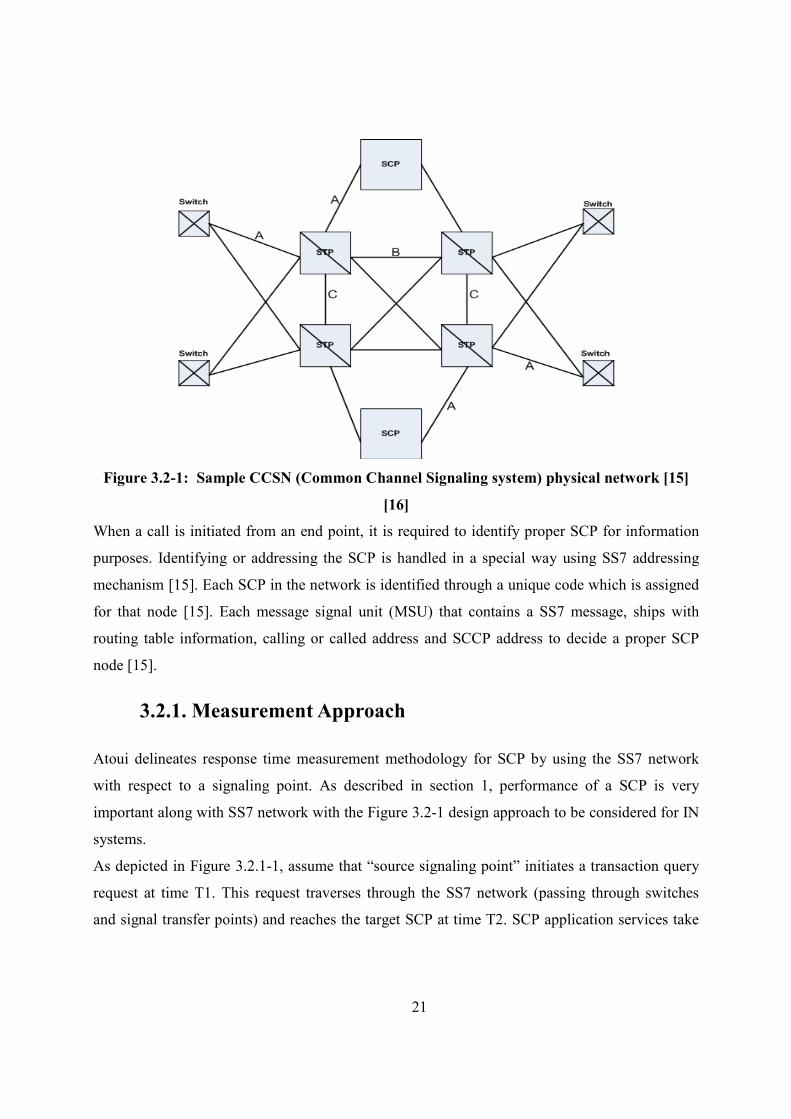
A node in a SS7 network is called signaling point (SP). There are several signaling points such as
Service Control Points (SCP), Signal Transfer Points (STP) (Figure 3.2-1). SCP is generally a
database used for transaction control purposes of different services. A signaling point generally
sends queries to SCP and corresponding responses are returned back [15].
Whereas STP is a signaling switch that routes & transports SS7 message packets by
manipulating the received message and based upon its configured routing table. As in Figure
3.2-1, STP’s are generally designed in parallel of two or more for redundancy, so that if one STP
fails the other node (redundant ones) can take over the load during failure scenario [15].
21
Figure 3.2-1: Sample CCS# (Common Channel Signaling system) physical network [15]
[16]
When a call is initiated from an end point, it is required to identify proper SCP for information
purposes. Identifying or addressing the SCP is handled in a special way using SS7 addressing
mechanism [15]. Each SCP in the network is identified through a unique code which is assigned
for that node [15]. Each message signal unit (MSU) that contains a SS7 message, ships with
routing table information, calling or called address and SCCP address to decide a proper SCP
node [15].
3.2.1. Measurement Approach
Atoui delineates response time measurement methodology for SCP by using the SS7 network
with respect to a signaling point. As described in section 1, performance of a SCP is very
important along with SS7 network with the Figure 3.2-1 design approach to be considered for IN
systems.
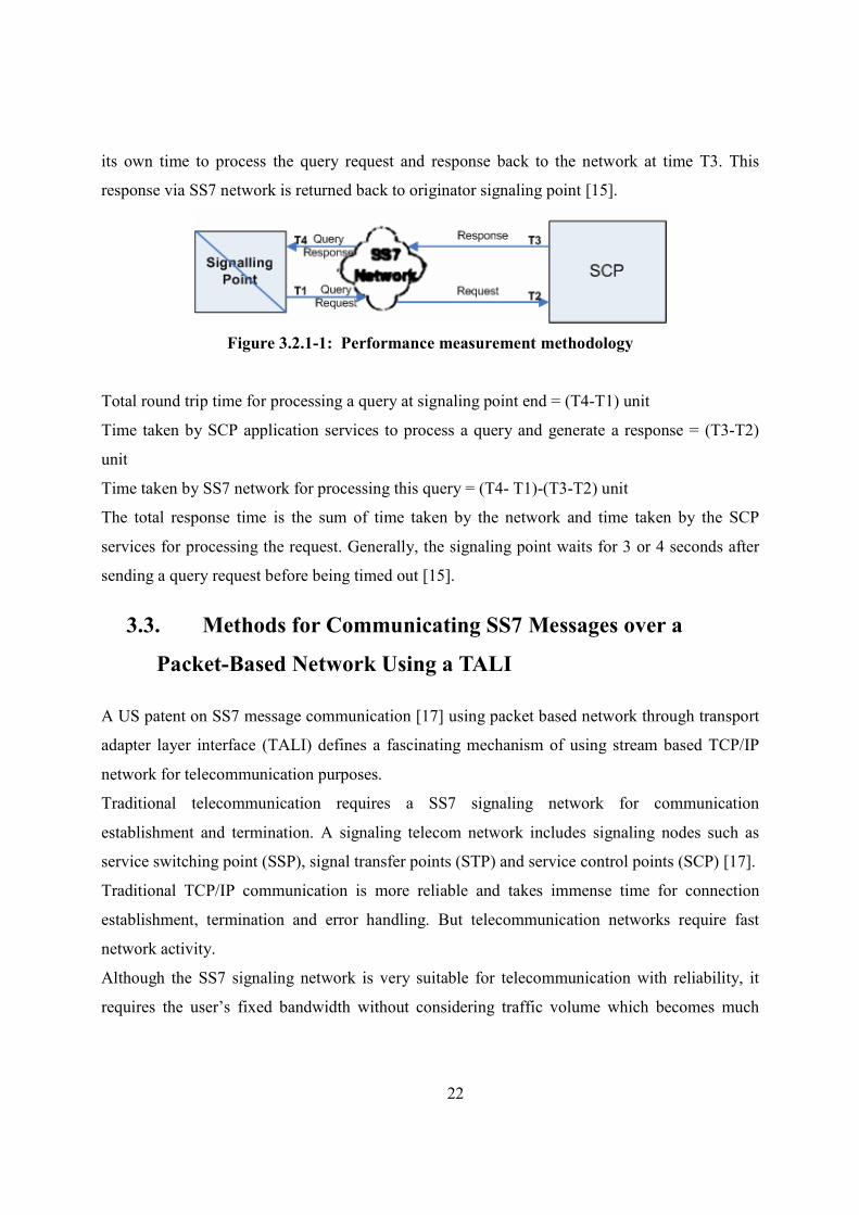
As depicted in Figure 3.2.1-1, assume that “source signaling point” initiates a transaction query
request at time T1. This request traverses through the SS7 network (passing through switches
and signal transfer points) and reaches the target SCP at time T2. SCP application services take
22
its own time to process the query request and response back to the network at time T3. This
response via SS7 network is returned back to originator signaling point [15].
Figure 3.2.1-1: Performance measurement methodology
Total round trip time for processing a query at signaling point end = (T4-T1) unit
Time taken by SCP application services to process a query and generate a response = (T3-T2)
unit
Time taken by SS7 network for processing this query = (T4- T1)-(T3-T2) unit
The total response time is the sum of time taken by the network and time taken by the SCP
services for processing the request. Generally, the signaling point waits for 3 or 4 seconds after
sending a query request before being timed out [15].
3.3. Methods for Communicating SS7 Messages over a
Packet-Based #etwork Using a TALI
A US patent on SS7 message communication [17] using packet based network through transport
adapter layer interface (TALI) defines a fascinating mechanism of using stream based TCP/IP
network for telecommunication purposes.
Traditional telecommunication requires a SS7 signaling network for communication
establishment and termination. A signaling telecom network includes signaling nodes such as
service switching point (SSP), signal transfer points (STP) and service control points (SCP) [17].
Traditional TCP/IP communication is more reliable and takes immense time for connection
establishment, termination and error handling. But telecommunication networks require fast
network activity.
Although the SS7 signaling network is very suitable for telecommunication with reliability, it
requires the user’s fixed bandwidth without considering traffic volume which becomes much
23
more expensive to bear [17]. However, TCP/IP network is more widely used, less expensive;
bandwidth is possible to share among multiple users [17].
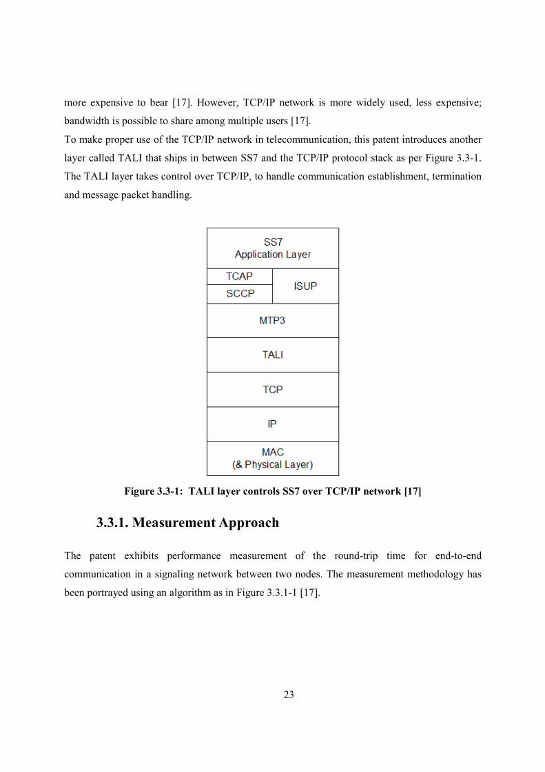
To make proper use of the TCP/IP network in telecommunication, this patent introduces another
layer called TALI that ships in between SS7 and the TCP/IP protocol stack as per Figure 3.3-1.
The TALI layer takes control over TCP/IP, to handle communication establishment, termination
and message packet handling.
Figure 3.3-1: TALI layer controls SS7 over TCP/IP network [17]
3.3.1. Measurement Approach
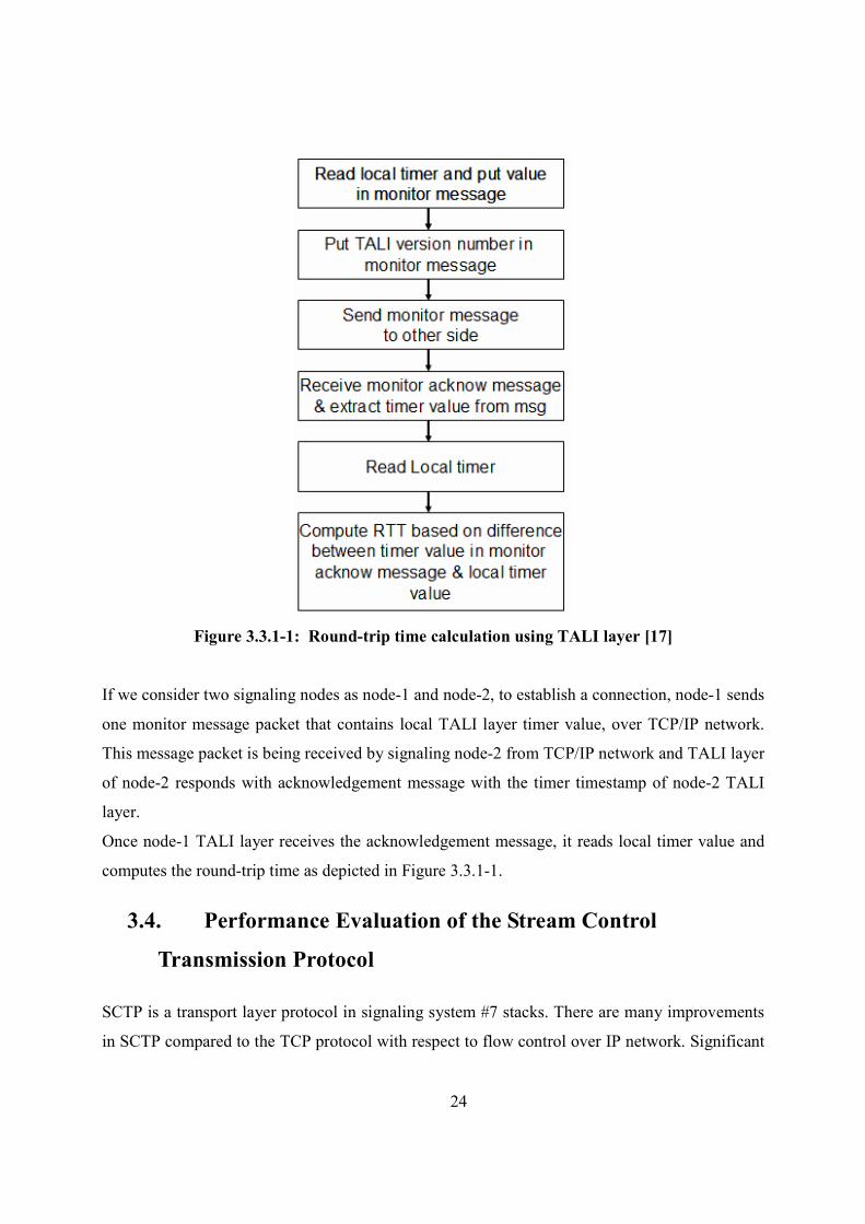
The patent exhibits performance measurement of the round-trip time for end-to-end
communication in a signaling network between two nodes. The measurement methodology has
been portrayed using an algorithm as in Figure 3.3.1-1 [17].
24
Figure 3.3.1-1: Round-trip time calculation using TALI layer [17]
If we consider two signaling nodes as node-1 and node-2, to establish a connection, node-1 sends
one monitor message packet that contains local TALI layer timer value, over TCP/IP network.
This message packet is being received by signaling node-2 from TCP/IP network and TALI layer
of node-2 responds with acknowledgement message with the timer timestamp of node-2 TALI
layer.
Once node-1 TALI layer receives the acknowledgement message, it reads local timer value and
computes the round-trip time as depicted in Figure 3.3.1-1.
3.4. Performance Evaluation of the Stream Control
Transmission Protocol
SCTP is a transport layer protocol in signaling system #7 stacks. There are many improvements
in SCTP compared to the TCP protocol with respect to flow control over IP network. Significant
25
improvements include order of arrival delivery, multiple messages packed into single SCTP
packet and inclusion of network level fault tolerance. The higher performance requirement of
SS7 is matched with inclusion of these changes in SCTP.
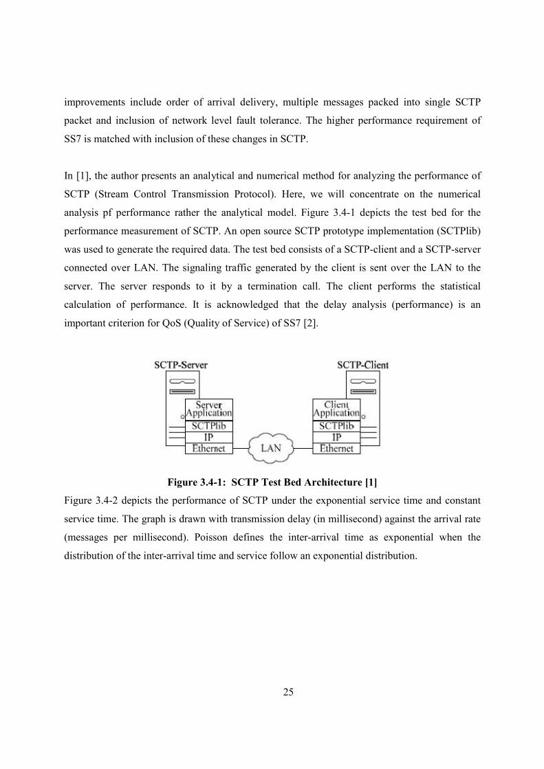
In [1], the author presents an analytical and numerical method for analyzing the performance of
SCTP (Stream Control Transmission Protocol). Here, we will concentrate on the numerical
analysis pf performance rather the analytical model. Figure 3.4-1 depicts the test bed for the
performance measurement of SCTP. An open source SCTP prototype implementation (SCTPlib)
was used to generate the required data. The test bed consists of a SCTP-client and a SCTP-server
connected over LAN. The signaling traffic generated by the client is sent over the LAN to the
server. The server responds to it by a termination call. The client performs the statistical
calculation of performance. It is acknowledged that the delay analysis (performance) is an
important criterion for QoS (Quality of Service) of SS7 [2].
Figure 3.4-1: SCTP Test Bed Architecture [1]
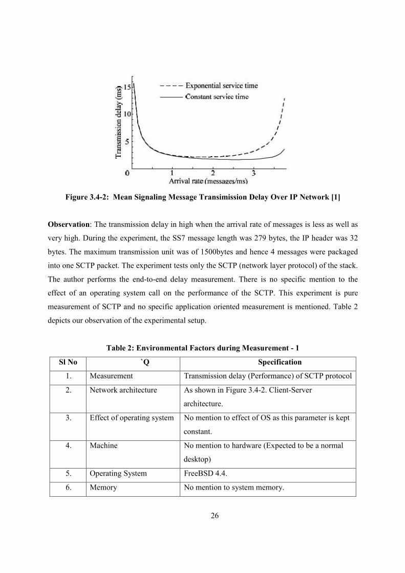
Figure 3.4-2 depicts the performance of SCTP under the exponential service time and constant
service time. The graph is drawn with transmission delay (in millisecond) against the arrival rate
(messages per millisecond). Poisson defines the inter-arrival time as exponential when the
distribution of the inter-arrival time and service follow an exponential distribution.
26
Figure 3.4-2: Mean Signaling Message Transimission Delay Over IP #etwork [1]
Observation: The transmission delay in high when the arrival rate of messages is less as well as
very high. During the experiment, the SS7 message length was 279 bytes, the IP header was 32
bytes. The maximum transmission unit was of 1500bytes and hence 4 messages were packaged
into one SCTP packet. The experiment tests only the SCTP (network layer protocol) of the stack.
The author performs the end-to-end delay measurement. There is no specific mention to the
effect of an operating system call on the performance of the SCTP. This experiment is pure
measurement of SCTP and no specific application oriented measurement is mentioned. Table 2
depicts our observation of the experimental setup.
Table 2: Environmental Factors during Measurement - 1
Sl #o `Q Specification
1. Measurement Transmission delay (Performance) of SCTP protocol
2. Network architecture As shown in Figure 3.4-2. Client-Server
architecture.
3. Effect of operating system No mention to effect of OS as this parameter is kept
constant.
4. Machine No mention to hardware (Expected to be a normal
desktop)
5. Operating System FreeBSD 4.4.
6. Memory No mention to system memory.
27
Sl #o `Q Specification
7. Network IP network (Local area network)
8. Network load Measured for exponential and normal service time.
9 Machine load Dedicated machine with no other user/program.
3.5. Performance Analysis of CCS#, based on SS#7
The Signaling System #7 (SS7) protocol forms the backbone of ISDN (Integrated Services
Digital Networks) and IN (Intelligent Networks) in call controls and inter-exchange message
signaling. SS7 hold fast a high QoS (Quality of Service) in call communication. Performance and
reliability form an important aspect of QoS. The physical architecture of signaling network
consists of SEP (Signaling end point), STP (Signaling transfer point) and Linksets. In ISDN,
each SEP consists of MTP, SCCP, ISDN-UP and TCAP layers. STP consists of MTP and SCCP.
These are the layers of SS7 that exists in SEP.
In [3], the author evaluates the mean end-to-end delay of single-mate pair (SMP) CCSN
(Common Channel Signaling Networks). This evaluation is performed under normal state as well
as under different failure states. The paper also analyses the failure rate of STP. The author
represents a comparative analysis of SS7 with OSI model, followed by a mathematical and
numerical model of performance analysis. Our area of focus is the numerical analysis of
performance in the CCSS systems.
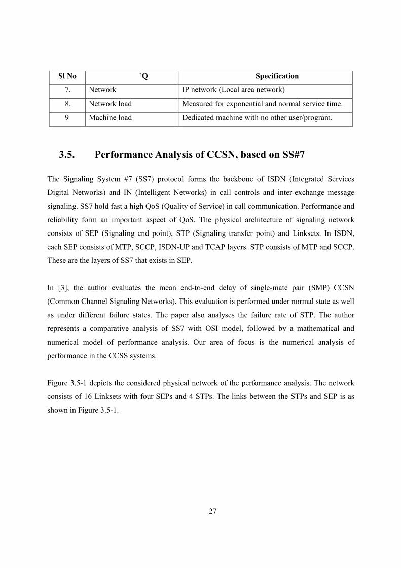
Figure 3.5-1 depicts the considered physical network of the performance analysis. The network
consists of 16 Linksets with four SEPs and 4 STPs. The links between the STPs and SEP is as
shown in Figure 3.5-1.
28
Figure 3.5-1: CCS# (Common Channel Signaling system) physical network [3]
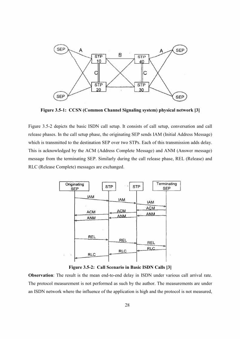
Figure 3.5-2 depicts the basic ISDN call setup. It consists of call setup, conversation and call
release phases. In the call setup phase, the originating SEP sends IAM (Initial Address Message)
which is transmitted to the destination SEP over two STPs. Each of this transmission adds delay.
This is acknowledged by the ACM (Address Complete Message) and ANM (Answer message)
message from the terminating SEP. Similarly during the call release phase, REL (Release) and
RLC (Release Complete) messages are exchanged.
Figure 3.5-2: Call Scenario in Basic ISD# Calls [3]
Observation: The result is the mean end-to-end delay in ISDN under various call arrival rate.
The protocol measurement is not performed as such by the author. The measurements are under
an ISDN network where the influence of the application is high and the protocol is not measured,
29
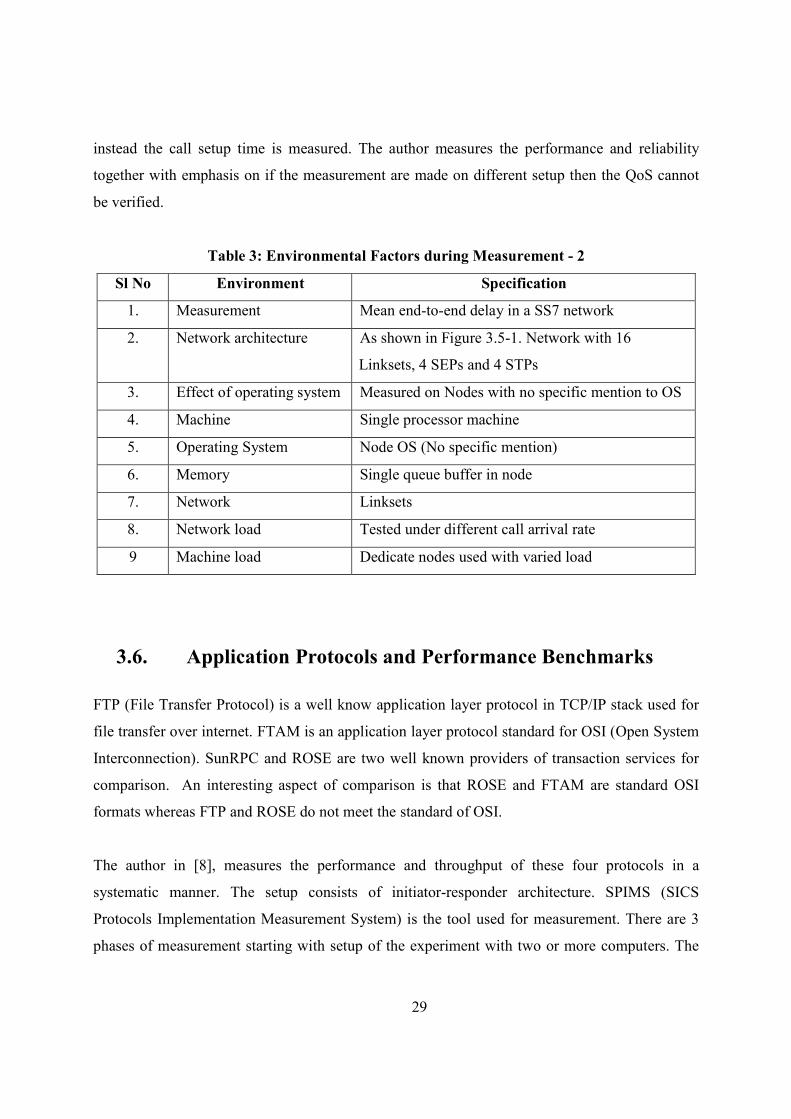
instead the call setup time is measured. The author measures the performance and reliability
together with emphasis on if the measurement are made on different setup then the QoS cannot
be verified.
Table 3: Environmental Factors during Measurement - 2
Sl #o Environment Specification
1. Measurement Mean end-to-end delay in a SS7 network
2. Network architecture As shown in Figure 3.5-1. Network with 16
Linksets, 4 SEPs and 4 STPs
3. Effect of operating system Measured on Nodes with no specific mention to OS
4. Machine Single processor machine
5. Operating System Node OS (No specific mention)
6. Memory Single queue buffer in node
7. Network Linksets
8. Network load Tested under different call arrival rate
9 Machine load Dedicate nodes used with varied load
3.6. Application Protocols and Performance Benchmarks
FTP (File Transfer Protocol) is a well know application layer protocol in TCP/IP stack used for
file transfer over internet. FTAM is an application layer protocol standard for OSI (Open System
Interconnection). SunRPC and ROSE are two well known providers of transaction services for
comparison. An interesting aspect of comparison is that ROSE and FTAM are standard OSI
formats whereas FTP and ROSE do not meet the standard of OSI.
The author in [8], measures the performance and throughput of these four protocols in a
systematic manner. The setup consists of initiator-responder architecture. SPIMS (SICS
Protocols Implementation Measurement System) is the tool used for measurement. There are 3
phases of measurement starting with setup of the experiment with two or more computers. The
30
second generates the messages that are passed through the protocol stack. The third stage
measures different parameters at the initiator’s end. There are 3 measurement parameters in the
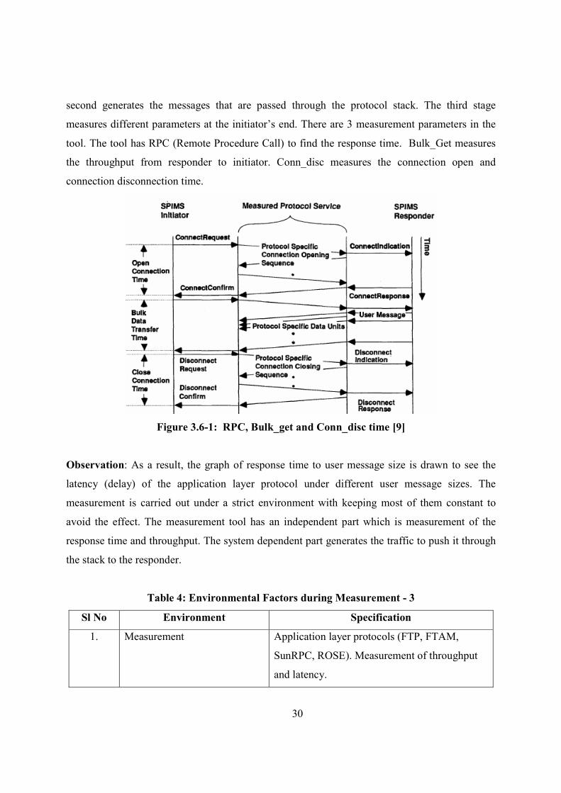
tool. The tool has RPC (Remote Procedure Call) to find the response time. Bulk_Get measures
the throughput from responder to initiator. Conn_disc measures the connection open and
connection disconnection time.
Figure 3.6-1: RPC, Bulk_get and Conn_disc time [9]
Observation: As a result, the graph of response time to user message size is drawn to see the
latency (delay) of the application layer protocol under different user message sizes. The
measurement is carried out under a strict environment with keeping most of them constant to
avoid the effect. The measurement tool has an independent part which is measurement of the
response time and throughput. The system dependent part generates the traffic to push it through
the stack to the responder.
Table 4: Environmental Factors during Measurement - 3
Sl #o Environment Specification
1. Measurement Application layer protocols (FTP, FTAM,
SunRPC, ROSE). Measurement of throughput
and latency.
31
Sl #o Environment Specification
2. Network architecture Initiator-Responder
3. Effect of operating system Not part of experiment
4. Machine SUN 3/60 (diskless)
5. Operating System Standard SunOS 3.5
6. Memory 4MB
7. Network Ethernet
8. Network load Some sample routing traffic (No network load
measured)
9 Machine load Single user machine with no other application
running
3.7. Processing and measuring SS7 message signal units
(MSU’s)
A US patent on collecting and processing SS7 message signal units (MSU’s) portrays processing
mechanism of call data records (CDR’s) for telecom billing perspective [22].
CDR is the ultimate unit of performing billing activity in telecom systems i.e. how much to bill a
particular customer. Hence generating these CDR’s is a challenge for telecom networks.
Telecom systems make use of SS7 MSU’s to generate these CDR as described in Figure 3.7-1.
32
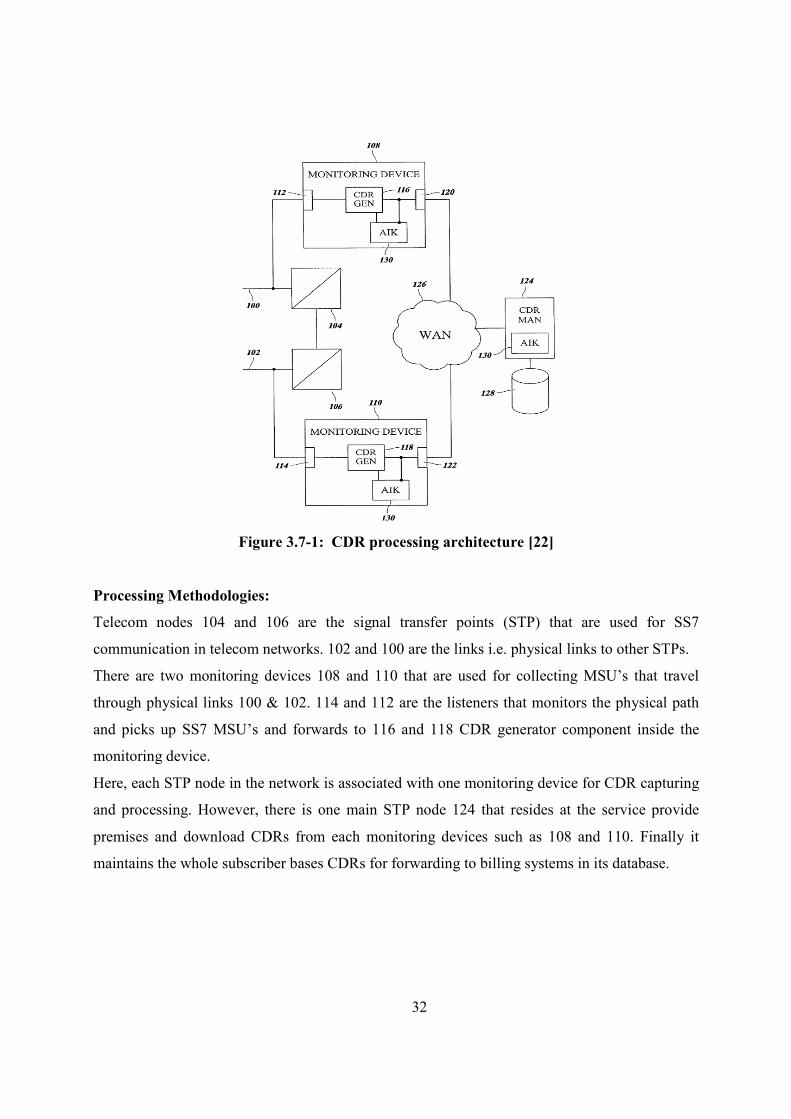
Figure 3.7-1: CDR processing architecture [22]
Processing Methodologies:
Telecom nodes 104 and 106 are the signal transfer points (STP) that are used for SS7
communication in telecom networks. 102 and 100 are the links i.e. physical links to other STPs.
There are two monitoring devices 108 and 110 that are used for collecting MSU’s that travel
through physical links 100 & 102. 114 and 112 are the listeners that monitors the physical path
and picks up SS7 MSU’s and forwards to 116 and 118 CDR generator component inside the
monitoring device.
Here, each STP node in the network is associated with one monitoring device for CDR capturing
and processing. However, there is one main STP node 124 that resides at the service provide
premises and download CDRs from each monitoring devices such as 108 and 110. Finally it
maintains the whole subscriber bases CDRs for forwarding to billing systems in its database.
33
3.8. Tele-traffic simulator with SS7 for circuit switched and
intelligent network
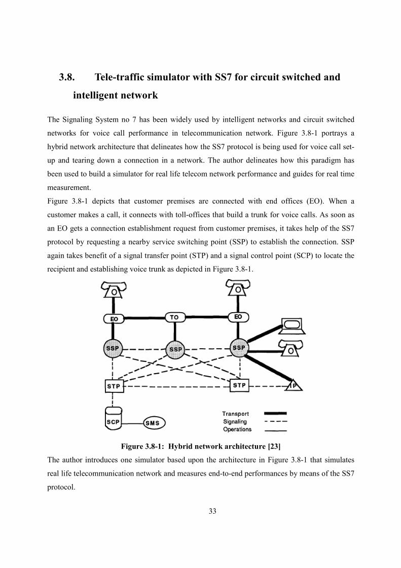
The Signaling System no 7 has been widely used by intelligent networks and circuit switched
networks for voice call performance in telecommunication network. Figure 3.8-1 portrays a
hybrid network architecture that delineates how the SS7 protocol is being used for voice call set-
up and tearing down a connection in a network. The author delineates how this paradigm has
been used to build a simulator for real life telecom network performance and guides for real time
measurement.
Figure 3.8-1 depicts that customer premises are connected with end offices (EO). When a
customer makes a call, it connects with toll-offices that build a trunk for voice calls. As soon as
an EO gets a connection establishment request from customer premises, it takes help of the SS7
protocol by requesting a nearby service switching point (SSP) to establish the connection. SSP
again takes benefit of a signal transfer point (STP) and a signal control point (SCP) to locate the
recipient and establishing voice trunk as depicted in Figure 3.8-1.
Figure 3.8-1: Hybrid network architecture [23]
The author introduces one simulator based upon the architecture in Figure 3.8-1 that simulates
real life telecommunication network and measures end-to-end performances by means of the SS7
protocol.
34
The simulator provides a user interface (UI) based display that allows the user to experiment
with different control switches that can be regulated according to real life scenarios. However,
the simulator does not simulate all the protocol layers of SS7. Rather concentrate only on SCCP
and TCAP as the other layers are used mainly for data framing, transport and application
services.
Simulator depends on two factors. Dynamic factors can be represented through creation,
execution and termination of processes, whereas static factors typically are system resources like
storage, memory.
3.9. Tools on SS7 Performance Analysis:
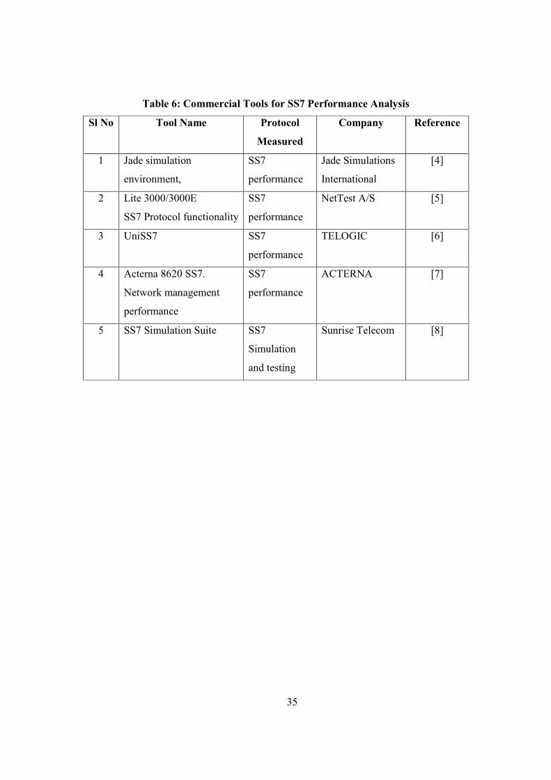
Table 6 presents the commercially available tools for measurement of the SS7 protocol. As these
are commercially available, we have chosen not to present them in this report. In a later stage,
the different measurement aspects of these commercial tools can be considered as an input while
we carry out measurement of the SS7 protocol stack.
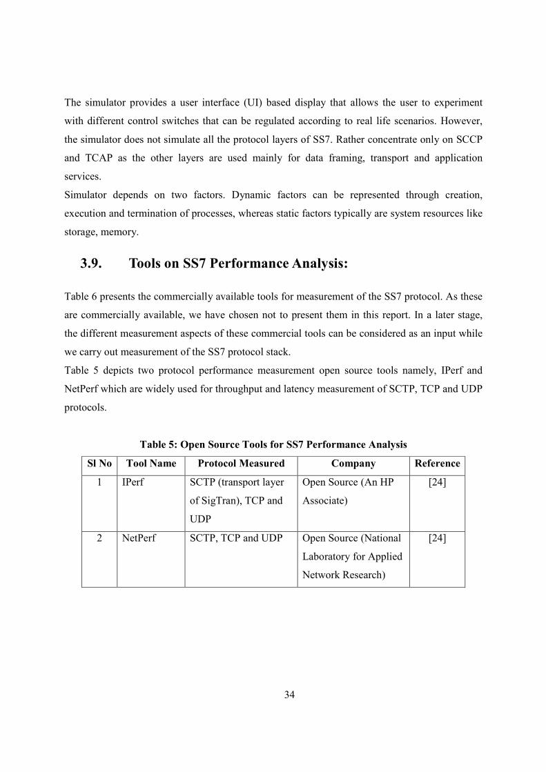
Table 5 depicts two protocol performance measurement open source tools namely, IPerf and
NetPerf which are widely used for throughput and latency measurement of SCTP, TCP and UDP
protocols.
Table 5: Open Source Tools for SS7 Performance Analysis
Sl #o Tool #ame Protocol Measured Company Reference
1 IPerf SCTP (transport layer
of SigTran), TCP and
UDP
Open Source (An HP
Associate)
[24]
2 NetPerf SCTP, TCP and UDP Open Source (National
Laboratory for Applied
Network Research)
[24]
35
Table 6: Commercial Tools for SS7 Performance Analysis
Sl #o Tool #ame Protocol
Measured
Company Reference
1 Jade simulation
environment,
SS7
performance
Jade Simulations
International
[4]
2 Lite 3000/3000E
SS7 Protocol functionality
SS7
performance
NetTest A/S [5]
3 UniSS7 SS7
performance
TELOGIC [6]
4 Acterna 8620 SS7.
Network management
performance
SS7
performance
ACTERNA [7]
5 SS7 Simulation Suite SS7
Simulation
and testing
Sunrise Telecom [8]
36
4. Protocol Performance Measurement Methodology
4.1. Complete Stack Measurement
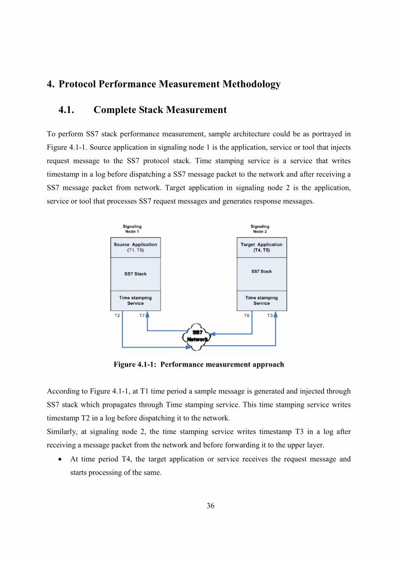
To perform SS7 stack performance measurement, sample architecture could be as portrayed in
Figure 4.1-1. Source application in signaling node 1 is the application, service or tool that injects
request message to the SS7 protocol stack. Time stamping service is a service that writes
timestamp in a log before dispatching a SS7 message packet to the network and after receiving a
SS7 message packet from network. Target application in signaling node 2 is the application,
service or tool that processes SS7 request messages and generates response messages.
Figure 4.1-1: Performance measurement approach
According to Figure 4.1-1, at T1 time period a sample message is generated and injected through
SS7 stack which propagates through Time stamping service. This time stamping service writes
timestamp T2 in a log before dispatching it to the network.
Similarly, at signaling node 2, the time stamping service writes timestamp T3 in a log after
receiving a message packet from the network and before forwarding it to the upper layer.
• At time period T4, the target application or service receives the request message and
starts processing of the same.
37
• At T5, this target application or service generates response message and responds to the
caller.
• At T6, time stamping service writes timestamp T6 in a log before dispatching the
response packet to the network.
• Again at T7, the response packet is received by signaling node 1 and its time stamping
service writes T7 in its log.
• At T8, the initiating application or service in signaling node 1 receives the response.
• Time taken to forward a request message by SS7 stack in signaling node 1 = (T2-T1) unit
• Time taken to receive the response message by source application (after processing of
SS7 stack) in signaling node 1 = (T8-T7) unit
• Time taken by signaling node 2 after receiving a request message and generating
response = (T6-T3) unit
• Time taken by target application in signaling node 2 to process a request message = (T5-
T4) unit
• Time taken by network = (T3-T2) + (T7-T6) unit
• Round trip time required for processing a request by the source application in signaling
node 1 = (T8-T1) unit
4.2. Stack Layer Measurement
A hypothetical measurement methodology is portrayed in Figure 4.2-1 and derived from the
concept depicted in Figure 3.3.1-1.
38
Figure 4.2-1: SS7 stack performance measurement methodology
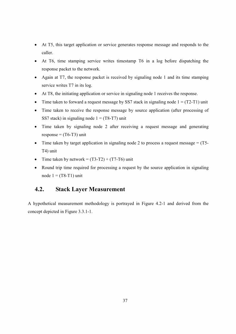
Figure 4.2-1 depict the SS7 protocol stack that will undergo performance measurement using a
monitor message by stamping local timer value. This timer value will be written either in a
common database or in a log file that will be read by an application in the SS7 application layer
to compute timing requirement of each layer for signaling message packet manipulation.
When the signaling node (Figure 4.2-1) receives a monitor message packet at MTP1 layer, it will
write ‘start time’ either in a database table or in a log file the local timer value and starts
processing on it.
Once the processing is completed by MTP1 layer, it will deliver the message to the upper layer
(MTP2) and again write the ‘end time’ in the database table or in the log file. A sample database
table or the log file content can be formulated as depicted in Figure 4.2-1. Similarly all the layers
in the stack will perform the same activity for ‘start time’ and ‘end time’ when a layer receives a
message packet and delivers it to the upper layer respectively. Now a test application at the SS7
application layer, will read the database table or the log file when it receives the message packet
from its below layer as portrayed in Figure 4.2-1. This test application will compute the timing
requirement for each protocol in SS7 stack for processing.
39
5. An Experimental Approach to Measure Performance
5.1. Experimentation
The experimental setup is based on client-server architecture. Client and server machines are
having an identical configuration. The client and server are connected by an Ethernet 100 Base-T
cable with a transmission capacity of 100 Mbits/second. The straight cable is used and hence a
switch is required in the LAN connection. An 8 port Gigabit switch is used for cross over. A
twisted Ethernet cable can eliminate the use of a switch. The two systems are configured with IP
addresses. Below are the hardware, software and test configurations.
• Hardware configuration
� Processor – Intel Pentium IV, 3GHz processor
� Cable - 100 Base T
� Switch – NetGear 8 port Gigabit Switch
� Interface card – Network Interface Card for IP communication
• Software configuration
� Operating system – Fedora 9
� Kernel version – 2.16.25-14.fc9.i686
� Open SS7 version - openss7-0.9.2.G
� IPerf version – iperf-2.0.8
� Netperf version – netperf-2.3.7
• Test configuration
� Message size - $n, this is a variable
� Test duration – 10 seconds
� Protocol measured – SCTP and TCP
� Bit rate - Output at different values of $n
� Port number – 5001
� Measured aspects – Throughput – Bytes of data sent per second (Mbps)
� Server IP: 130.243.75.14
� Client IP: 130.243.75.15
40
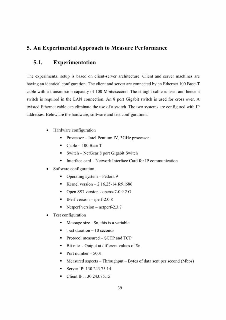
Figure 5.1-1: Experimental Setup for Performance Measurement
Figure 5.1-1 depicts the architectural view of the experimentation with a client-server. At the
client side, the IPerf client runs as the application over the Open SS7 kernel module. When the
test is performed, the client injects the test data into the stack and then to the physical medium.
The server is listening for the response at port 5001(default port).
5.2. IPerf Performance Measurement Tool
IPerf is a common network performance tool developed in C++ used to measure TCP and UDP
protocols. The release iperf-2.0.8 by Open SS7 community supports SCTP protocol
measurement. IPerf allows the user to set various network parameters like buffer size, message
length, time interval and various other parameters as shown in Table 9. IPerf has client-server
architecture with the tool running on one system as client and the other system as server. Figure
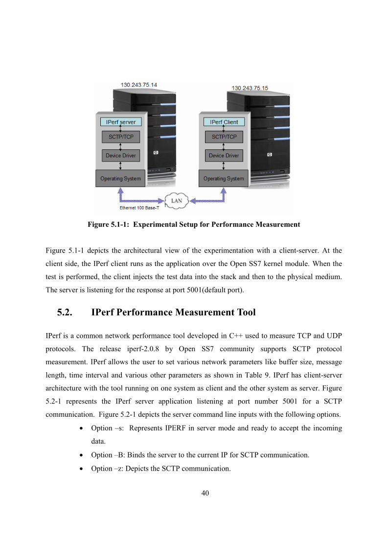
5.2-1 represents the IPerf server application listening at port number 5001 for a SCTP
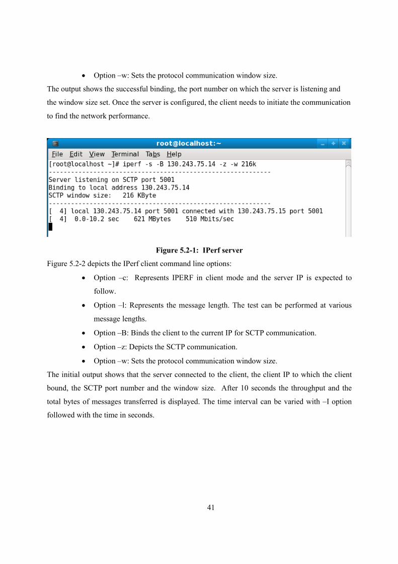
communication. Figure 5.2-1 depicts the server command line inputs with the following options.
• Option –s: Represents IPERF in server mode and ready to accept the incoming
data.
• Option –B: Binds the server to the current IP for SCTP communication.
• Option –z: Depicts the SCTP communication.
41
• Option –w: Sets the protocol communication window size.
The output shows the successful binding, the port number on which the server is listening and
the window size set. Once the server is configured, the client needs to initiate the communication
to find the network performance.
Figure 5.2-1: IPerf server
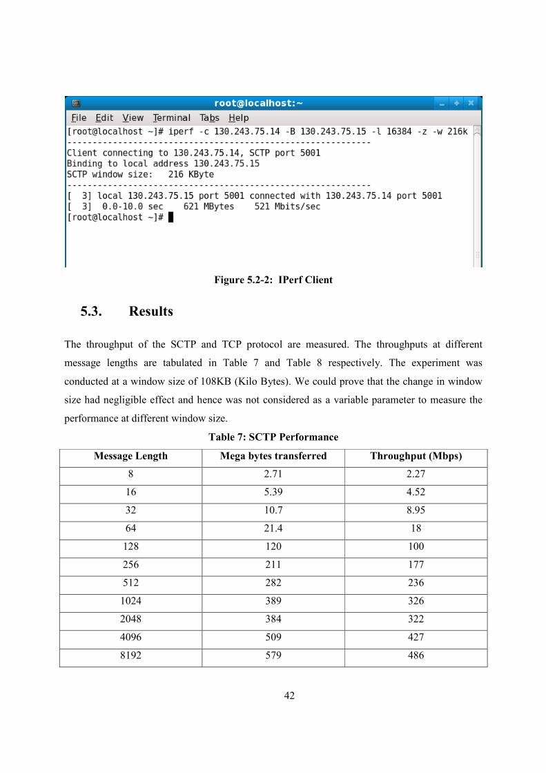
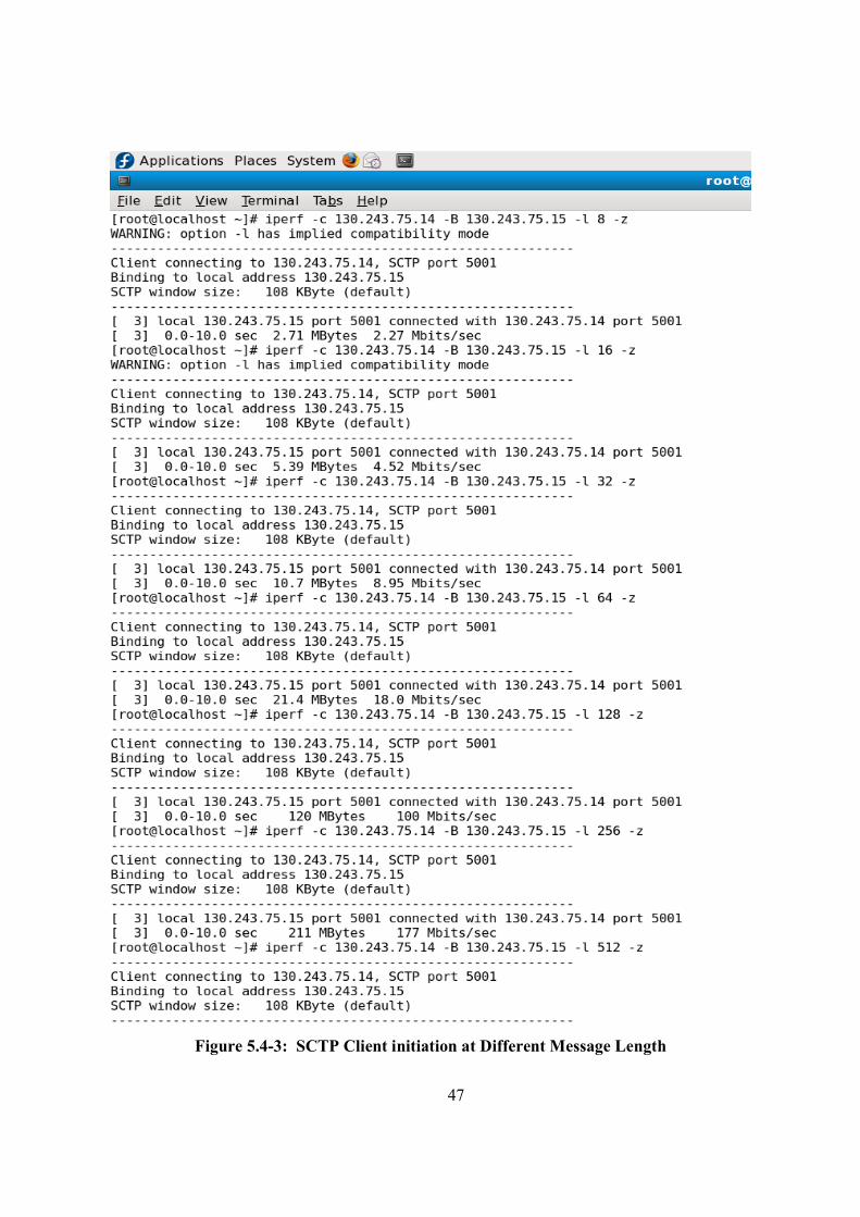
Figure 5.2-2 depicts the IPerf client command line options:
• Option –c: Represents IPERF in client mode and the server IP is expected to
follow.
• Option –l: Represents the message length. The test can be performed at various
message lengths.
• Option –B: Binds the client to the current IP for SCTP communication.
• Option –z: Depicts the SCTP communication.
• Option –w: Sets the protocol communication window size.
The initial output shows that the server connected to the client, the client IP to which the client
bound, the SCTP port number and the window size. After 10 seconds the throughput and the
total bytes of messages transferred is displayed. The time interval can be varied with –I option
followed with the time in seconds.
42
Figure 5.2-2: IPerf Client
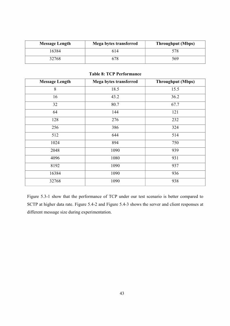
5.3. Results
The throughput of the SCTP and TCP protocol are measured. The throughputs at different
message lengths are tabulated in Table 7 and Table 8 respectively. The experiment was
conducted at a window size of 108KB (Kilo Bytes). We could prove that the change in window
size had negligible effect and hence was not considered as a variable parameter to measure the
performance at different window size.
Table 7: SCTP Performance
Message Length Mega bytes transferred Throughput (Mbps)
8 2.71 2.27
16 5.39 4.52
32 10.7 8.95
64 21.4 18
128 120 100
256 211 177
512 282 236
1024 389 326
2048 384 322
4096 509 427
8192 579 486
43
Message Length Mega bytes transferred Throughput (Mbps)
16384 614 578
32768 678 569
Table 8: TCP Performance
Message Length Mega bytes transferred Throughput (Mbps)
8 18.5 15.5
16 43.2 36.2
32 80.7 67.7
64 144 121
128 276 232
256 386 324
512 644 514
1024 894 750
2048 1090 939
4096 1080 931
8192 1090 937
16384 1090 936
32768 1090 938
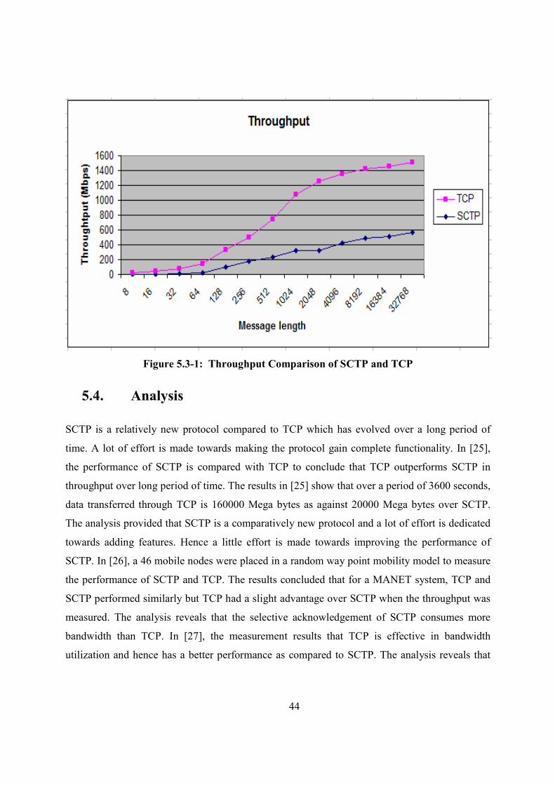
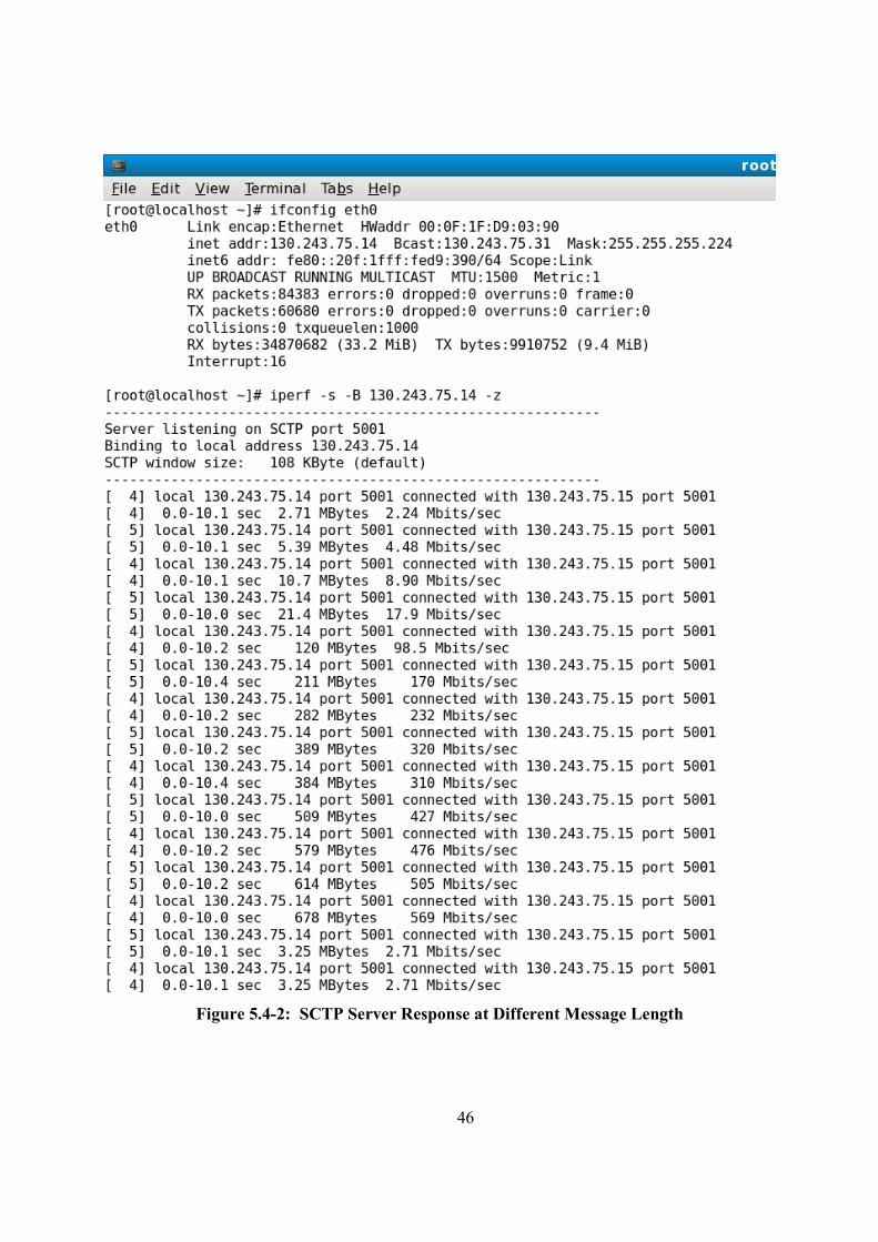
Figure 5.3-1 show that the performance of TCP under our test scenario is better compared to
SCTP at higher data rate. Figure 5.4-2 and Figure 5.4-3 shows the server and client responses at
different message size during experimentation.
44
Figure 5.3-1: Throughput Comparison of SCTP and TCP
5.4. Analysis
SCTP is a relatively new protocol compared to TCP which has evolved over a long period of
time. A lot of effort is made towards making the protocol gain complete functionality. In [25],
the performance of SCTP is compared with TCP to conclude that TCP outperforms SCTP in
throughput over long period of time. The results in [25] show that over a period of 3600 seconds,
data transferred through TCP is 160000 Mega bytes as against 20000 Mega bytes over SCTP.
The analysis provided that SCTP is a comparatively new protocol and a lot of effort is dedicated
towards adding features. Hence a little effort is made towards improving the performance of
SCTP. In [26], a 46 mobile nodes were placed in a random way point mobility model to measure
the performance of SCTP and TCP. The results concluded that for a MANET system, TCP and
SCTP performed similarly but TCP had a slight advantage over SCTP when the throughput was
measured. The analysis reveals that the selective acknowledgement of SCTP consumes more
bandwidth than TCP. In [27], the measurement results that TCP is effective in bandwidth
utilization and hence has a better performance as compared to SCTP. The analysis reveals that
45
the best and worst case time delivery of packets were at 11% and 61% as compared to SCTP
which has 60% and 89% as its best and worst case results in case of one in every 10 packets lost.
The most interesting results are produced in [24] with the performance of SCTP and TCP being
almost the same when a single Network Interface Card (NIC) is used. The measurements were
carried out with two experimental setups, one with a single NIC and one with two NIC. When
two NIC were used, the performance of SCTP outperformed TCP with almost double
throughput.
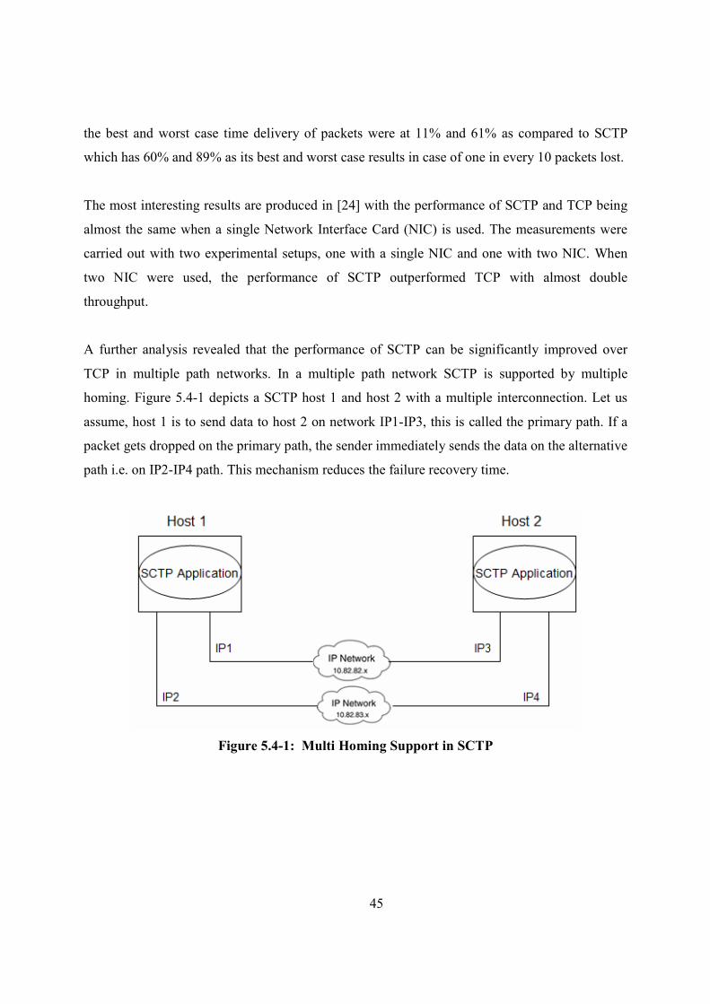
A further analysis revealed that the performance of SCTP can be significantly improved over
TCP in multiple path networks. In a multiple path network SCTP is supported by multiple
homing. Figure 5.4-1 depicts a SCTP host 1 and host 2 with a multiple interconnection. Let us
assume, host 1 is to send data to host 2 on network IP1-IP3, this is called the primary path. If a
packet gets dropped on the primary path, the sender immediately sends the data on the alternative
path i.e. on IP2-IP4 path. This mechanism reduces the failure recovery time.
Figure 5.4-1: Multi Homing Support in SCTP
46
Figure 5.4-2: SCTP Server Response at Different Message Length
47
Figure 5.4-3: SCTP Client initiation at Different Message Length
48
6. Summary and Conclusion
This report introduces the reader to the basic call set-up in a mobile communication and the
various telecommunication sub systems involved in the call set-up scenario. The focus in the
initial chapter is to depict the communication protocol involved in the telecommunication
network. The open source communication protocols and Ericsson proprietary communication
protocols are dealt in detail with their analogy. The analogy reveals that the CPP Signaling
system supports different types of networks for SS7 communication. These two protocol stacks
are seen as black boxes due to the unavailability of their design and internal architecture. SCTP
being an important transport layer protocol of SS7 over the IP network, the performance of the
SCTP protocol is of importance. TCP is the most popular transport layer protocol which was not
suited for SS7 over IP due to the fact that TCP has strict sequential delivery of packets and has
large timeout granularity. The experimentation was carried out to check whether SCTP has
evolved to the level of performance that TCP promises.
The experimentation carried out with the hardware set-up in the lab does a throughput
performance measurement of SCTP and TCP. The experimental results show that TCP performs
better than SCTP with a single NIC (Network Interface Card) but the analysis yields that SCTP
can outperform TCP with the multi homing support. SCTP provides major advantage of
unordered delivery and reassembly at the receiving end, SCTP support multiple stream and multi
homing which is not supported in TCP. The experiment also revealed that the window size did
not have a large effect on throughout for both SCTP and TCP.
7. Future Work
This thesis sets a platform for further comparison of protocol stack of the open source
community and Ericsson proprietary. The various alternatives for future work are as follows:
The Open SS7 could be tried out on a CPP node to test the performance of SS7 communication
on a CPP node with OSE Delta Operating system running on it. In this perspective, the current
thesis differs only with respect to the platform as we have tried on a Pentium IV processor. This
would lead to performance comparison of a non-real time operating to a real time operating
system.

49
The current thesis has the limitation of having open SS7 and CPP SS7 on a different platforms.
Hence the open SS7 and Ericsson proprietary SS7 performance can not be compared. By
installing Open SS7 on a node will ensure that the environmental factors for both types of SS7 is
the same and their performance purely depend on the design and implementation of protocol
stack. The importance of this approach is to compare protocol with protocol in two different
stacks and find the better one.
The two proposed methodologies of measuring stack and individual protocol are of specific
importance to find the bottle neck in the network. The methodologies use the method of time
stamping the message traversal through different layers of the protocol stack. The importance of
this aspect is to find the layer where the time is spent a lot in the network and hence work
towards better design of the layer.
50
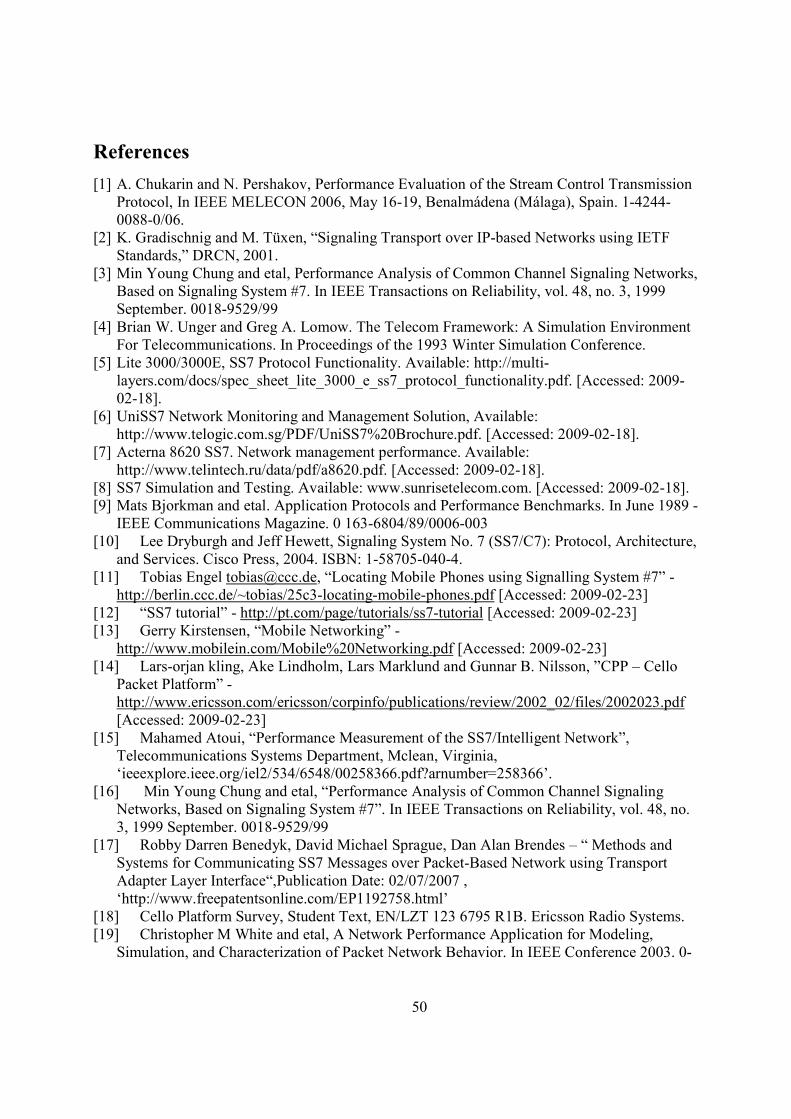
References
[1] A. Chukarin and N. Pershakov, Performance Evaluation of the Stream Control Transmission Protocol, In IEEE MELECON 2006, May 16-19, Benalmádena (Málaga), Spain. 1-4244-0088-0/06.
[2] K. Gradischnig and M. Tüxen, “Signaling Transport over IP-based Networks using IETF Standards,” DRCN, 2001.
[3] Min Young Chung and etal, Performance Analysis of Common Channel Signaling Networks, Based on Signaling System #7. In IEEE Transactions on Reliability, vol. 48, no. 3, 1999 September. 0018-9529/99
[4] Brian W. Unger and Greg A. Lomow. The Telecom Framework: A Simulation Environment For Telecommunications. In Proceedings of the 1993 Winter Simulation Conference.
[5] Lite 3000/3000E, SS7 Protocol Functionality. Available: http://multi-layers.com/docs/spec_sheet_lite_3000_e_ss7_protocol_functionality.pdf. [Accessed: 2009-02-18].
[6] UniSS7 Network Monitoring and Management Solution, Available: http://www.telogic.com.sg/PDF/UniSS7%20Brochure.pdf. [Accessed: 2009-02-18].
[7] Acterna 8620 SS7. Network management performance. Available: http://www.telintech.ru/data/pdf/a8620.pdf. [Accessed: 2009-02-18].
[8] SS7 Simulation and Testing. Available: www.sunrisetelecom.com. [Accessed: 2009-02-18]. [9] Mats Bjorkman and etal. Application Protocols and Performance Benchmarks. In June 1989 -
IEEE Communications Magazine. 0 163-6804/89/0006-003 [10] Lee Dryburgh and Jeff Hewett, Signaling System No. 7 (SS7/C7): Protocol, Architecture,
and Services. Cisco Press, 2004. ISBN: 1-58705-040-4. [11] Tobias Engel [email protected], “Locating Mobile Phones using Signalling System #7” -
http://berlin.ccc.de/~tobias/25c3-locating-mobile-phones.pdf [Accessed: 2009-02-23] [12] “SS7 tutorial” - http://pt.com/page/tutorials/ss7-tutorial [Accessed: 2009-02-23] [13] Gerry Kirstensen, “Mobile Networking” -
http://www.mobilein.com/Mobile%20Networking.pdf [Accessed: 2009-02-23] [14] Lars-orjan kling, Ake Lindholm, Lars Marklund and Gunnar B. Nilsson, ”CPP – Cello
Packet Platform” - http://www.ericsson.com/ericsson/corpinfo/publications/review/2002_02/files/2002023.pdf [Accessed: 2009-02-23]
[15] Mahamed Atoui, “Performance Measurement of the SS7/Intelligent Network”, Telecommunications Systems Department, Mclean, Virginia, ‘ieeexplore.ieee.org/iel2/534/6548/00258366.pdf?arnumber=258366’.
[16] Min Young Chung and etal, “Performance Analysis of Common Channel Signaling Networks, Based on Signaling System #7”. In IEEE Transactions on Reliability, vol. 48, no. 3, 1999 September. 0018-9529/99
[17] Robby Darren Benedyk, David Michael Sprague, Dan Alan Brendes – “ Methods and Systems for Communicating SS7 Messages over Packet-Based Network using Transport Adapter Layer Interface“,Publication Date: 02/07/2007 , ‘http://www.freepatentsonline.com/EP1192758.html’
[18] Cello Platform Survey, Student Text, EN/LZT 123 6795 R1B. Ericsson Radio Systems. [19] Christopher M White and etal, A Network Performance Application for Modeling,
Simulation, and Characterization of Packet Network Behavior. In IEEE Conference 2003. 0-
51
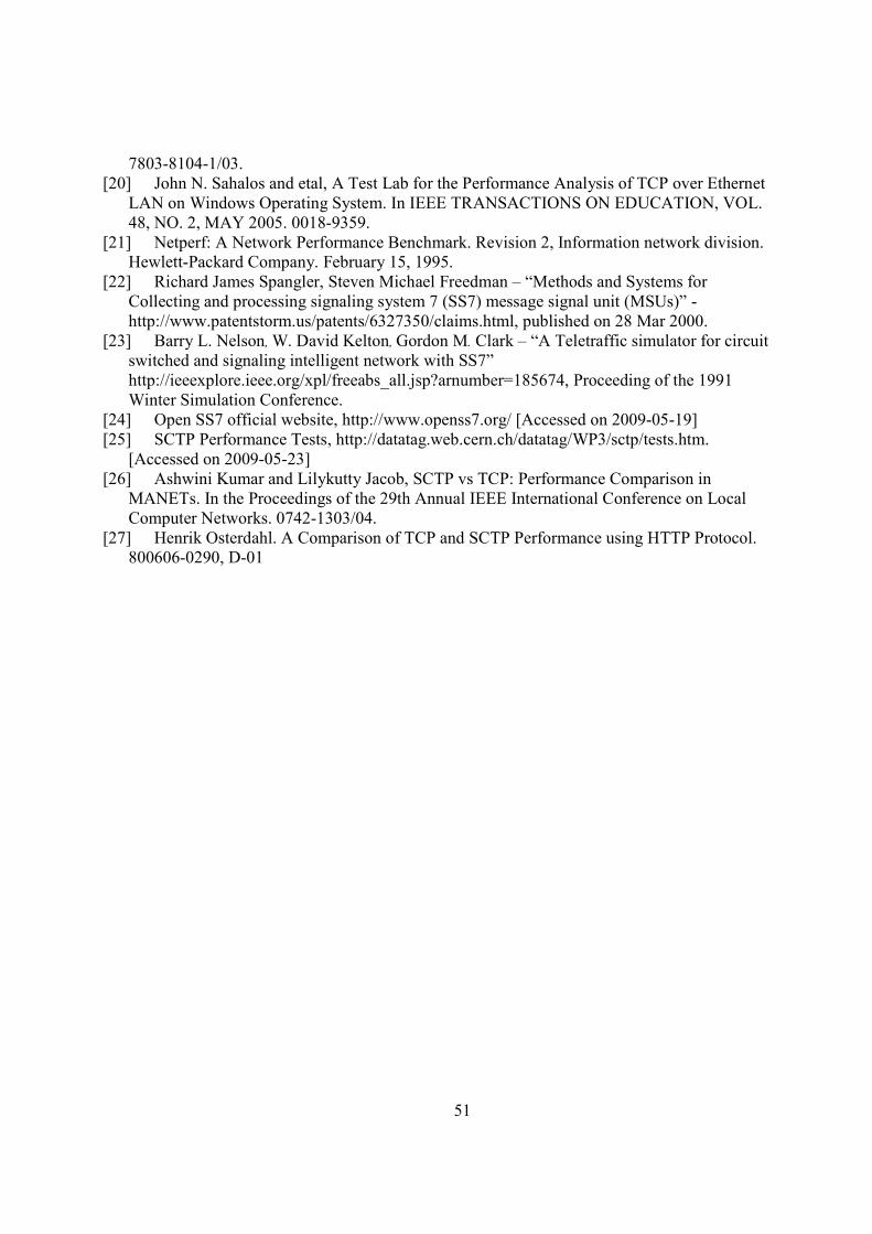
7803-8104-1/03. [20] John N. Sahalos and etal, A Test Lab for the Performance Analysis of TCP over Ethernet
LAN on Windows Operating System. In IEEE TRANSACTIONS ON EDUCATION, VOL. 48, NO. 2, MAY 2005. 0018-9359.
[21] Netperf: A Network Performance Benchmark. Revision 2, Information network division. Hewlett-Packard Company. February 15, 1995.
[22] Richard James Spangler, Steven Michael Freedman – “Methods and Systems for Collecting and processing signaling system 7 (SS7) message signal unit (MSUs)” -http://www.patentstorm.us/patents/6327350/claims.html, published on 28 Mar 2000.
[23] Barry L. Nelson, W. David Kelton, Gordon M. Clark – “A Teletraffic simulator for circuit switched and signaling intelligent network with SS7” http://ieeexplore.ieee.org/xpl/freeabs_all.jsp?arnumber=185674, Proceeding of the 1991 Winter Simulation Conference.
[24] Open SS7 official website, http://www.openss7.org/ [Accessed on 2009-05-19] [25] SCTP Performance Tests, http://datatag.web.cern.ch/datatag/WP3/sctp/tests.htm.
[Accessed on 2009-05-23] [26] Ashwini Kumar and Lilykutty Jacob, SCTP vs TCP: Performance Comparison in
MANETs. In the Proceedings of the 29th Annual IEEE International Conference on Local Computer Networks. 0742-1303/04.
[27] Henrik Osterdahl. A Comparison of TCP and SCTP Performance using HTTP Protocol. 800606-0290, D-01
52
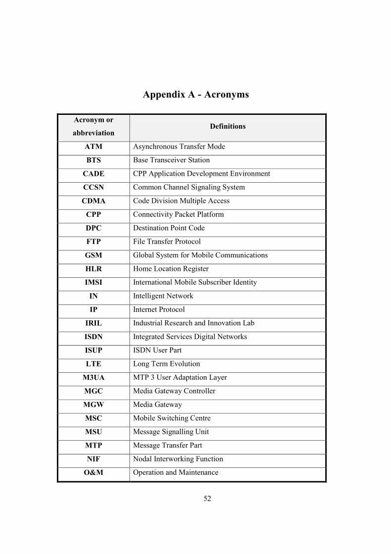
Appendix A - Acronyms
Acronym or
abbreviation Definitions
ATM Asynchronous Transfer Mode
BTS Base Transceiver Station
CADE CPP Application Development Environment
CCS# Common Channel Signaling System
CDMA Code Division Multiple Access
CPP Connectivity Packet Platform
DPC Destination Point Code
FTP File Transfer Protocol
GSM Global System for Mobile Communications
HLR Home Location Register
IMSI International Mobile Subscriber Identity
I# Intelligent Network
IP Internet Protocol
IRIL Industrial Research and Innovation Lab
ISD# Integrated Services Digital Networks
ISUP ISDN User Part
LTE Long Term Evolution
M3UA MTP 3 User Adaptation Layer
MGC Media Gateway Controller
MGW Media Gateway
MSC Mobile Switching Centre
MSU Message Signalling Unit
MTP Message Transfer Part
#IF Nodal Interworking Function
O&M Operation and Maintenance
53
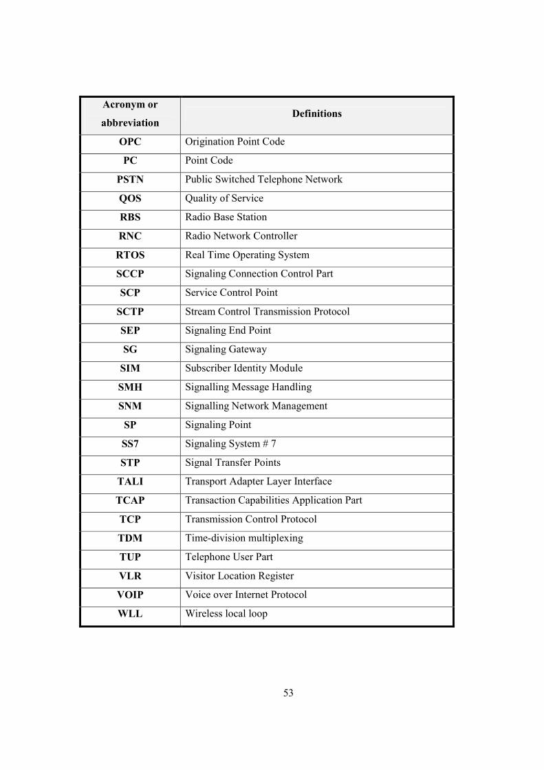
Acronym or
abbreviation Definitions
OPC Origination Point Code
PC Point Code
PST# Public Switched Telephone Network
QOS Quality of Service
RBS Radio Base Station
R#C Radio Network Controller
RTOS Real Time Operating System
SCCP Signaling Connection Control Part
SCP Service Control Point
SCTP Stream Control Transmission Protocol
SEP Signaling End Point
SG Signaling Gateway
SIM Subscriber Identity Module
SMH Signalling Message Handling
S#M Signalling Network Management
SP Signaling Point
SS7 Signaling System # 7
STP Signal Transfer Points
TALI Transport Adapter Layer Interface
TCAP Transaction Capabilities Application Part
TCP Transmission Control Protocol
TDM Time-division multiplexing
TUP Telephone User Part
VLR Visitor Location Register
VOIP Voice over Internet Protocol
WLL Wireless local loop
54
Appendix B - Open SS7 Installation and Troubleshooting
Release Packages
Open SS7 has five major master package releases in the recent time. openss7-0.9.2.G.tar.bz2
being the latest release is considered for installation. Open SS7 master packages are not released
often but the sub packages are released frequently. To embed a sub-package release into the
master package, the sub package should be placed within the master package. Once the directory
is replaced, the master package has to be recompiled. The downloads are available at [24].
1. openss7-0.9.2.C.tar.bz2
2. openss7-0.9.2.D.tar.bz2
3. openss7-0.9.2.E.tar.bz2
4. openss7-0.9.2.F.tar.bz2
5. openss7-0.9.2.G.tar.bz2
Apart from master package releases openss7 has individual ss7 stack releases. These packages
have dependencies on other package releases. The binary compiled packages are also available
for download.
1. strss7-0.9a.8-1.noarch.rpm
Operating systems
The installation was carried on three different operating systems. All three were in accordance to
the system requirement specified in the installation manual of openss7. Open SS7 is supported
by kernel version 2.4 and 2.6. Later, the installation was concentrated on fedora system because
of easy availability of the dependent packages as listed in the next section “Package
Dependencies”.
1. Fedora 9 with kernel version 2.6.25-14.fc9.i686
2. Ubuntu 8.10 with kernel version 2.6.27
3. Ubuntu 8.04 with kernel version 2.6.24
System requirements
The below are the system requirement to be satisfied before installing open SS7.
55
• A fairly LSB compliant GNU/Linux distribution.1
• Linux 2.4 kernel (2.4.10 - 2.4.27), or
• Linux 2.6 kernel (2.6.3 - 2.6.26)
• glibc2 or better.
• GNU grof (for man pages).2
• GNU texinfo (for info les).
• GNU bison and ex (for cong programs).
• net-snmp (for SNMP agents).
Package dependencies
As openss7 installation is kernel module installation, a lot of development packages dependency
exists which are not available with the normal operating system installation. The below depicts
the package dependencies. The below installation were performed with downloading the specific
version of package compatible to the kernel version 2.6.25-14.fc9.i686 of Fedora 9 operating
system.
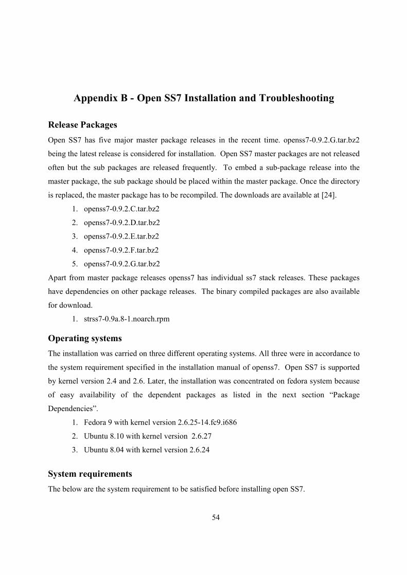
1. GCC compiler package
2. Kernel development package
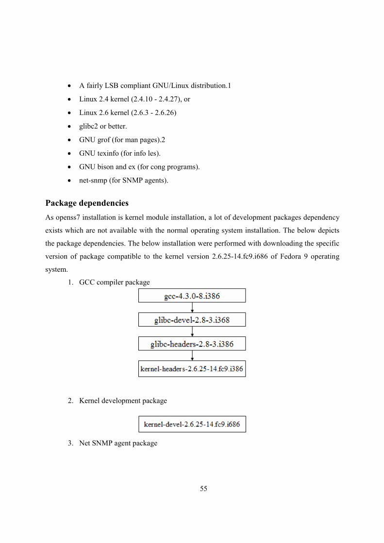
3. Net SNMP agent package
56
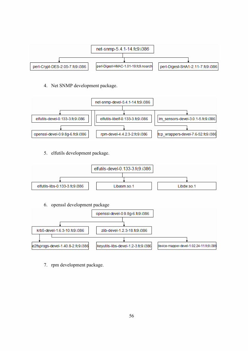
4. Net SNMP development package.
5. elfutils development package.
6. openssl development package
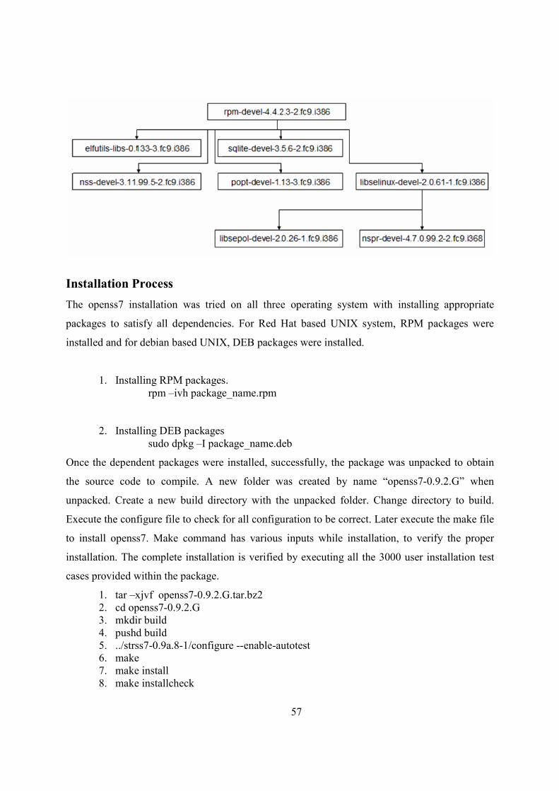
7. rpm development package.
57
Installation Process
The openss7 installation was tried on all three operating system with installing appropriate
packages to satisfy all dependencies. For Red Hat based UNIX system, RPM packages were
installed and for debian based UNIX, DEB packages were installed.
1. Installing RPM packages. rpm –ivh package_name.rpm
2. Installing DEB packages sudo dpkg –I package_name.deb
Once the dependent packages were installed, successfully, the package was unpacked to obtain
the source code to compile. A new folder was created by name “openss7-0.9.2.G” when
unpacked. Create a new build directory with the unpacked folder. Change directory to build.
Execute the configure file to check for all configuration to be correct. Later execute the make file
to install openss7. Make command has various inputs while installation, to verify the proper
installation. The complete installation is verified by executing all the 3000 user installation test
cases provided within the package.
1. tar –xjvf openss7-0.9.2.G.tar.bz2 2. cd openss7-0.9.2.G 3. mkdir build 4. pushd build 5. ../strss7-0.9a.8-1/configure --enable-autotest 6. make 7. make install 8. make installcheck
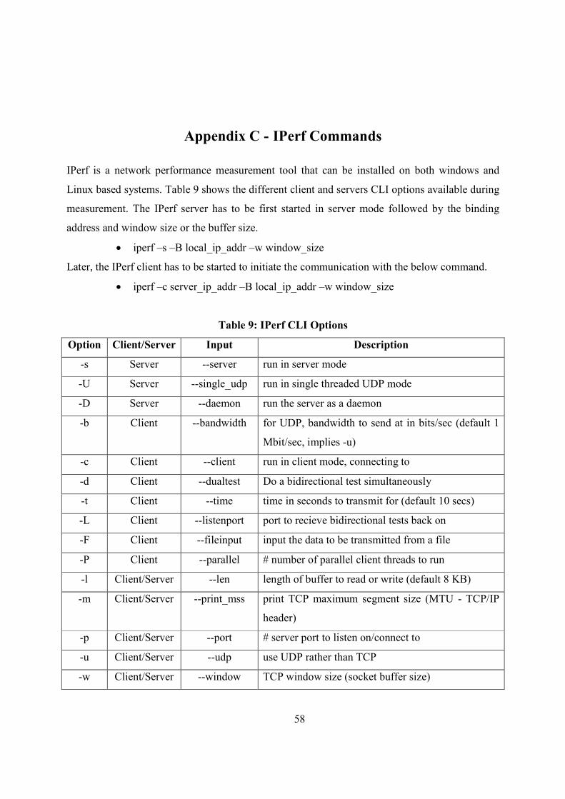
58
Appendix C - IPerf Commands
IPerf is a network performance measurement tool that can be installed on both windows and
Linux based systems. Table 9 shows the different client and servers CLI options available during
measurement. The IPerf server has to be first started in server mode followed by the binding
address and window size or the buffer size.
• iperf –s –B local_ip_addr –w window_size
Later, the IPerf client has to be started to initiate the communication with the below command.
• iperf –c server_ip_addr –B local_ip_addr –w window_size
Table 9: IPerf CLI Options
Option Client/Server Input Description
-s Server --server run in server mode
-U Server --single_udp run in single threaded UDP mode
-D Server --daemon run the server as a daemon
-b Client --bandwidth for UDP, bandwidth to send at in bits/sec (default 1
Mbit/sec, implies -u)
-c Client --client run in client mode, connecting to
-d Client --dualtest Do a bidirectional test simultaneously
-t Client --time time in seconds to transmit for (default 10 secs)
-L Client --listenport port to recieve bidirectional tests back on
-F Client --fileinput input the data to be transmitted from a file
-P Client --parallel # number of parallel client threads to run
-l Client/Server --len length of buffer to read or write (default 8 KB)
-m Client/Server --print_mss print TCP maximum segment size (MTU - TCP/IP
header)
-p Client/Server --port # server port to listen on/connect to
-u Client/Server --udp use UDP rather than TCP
-w Client/Server --window TCP window size (socket buffer size)
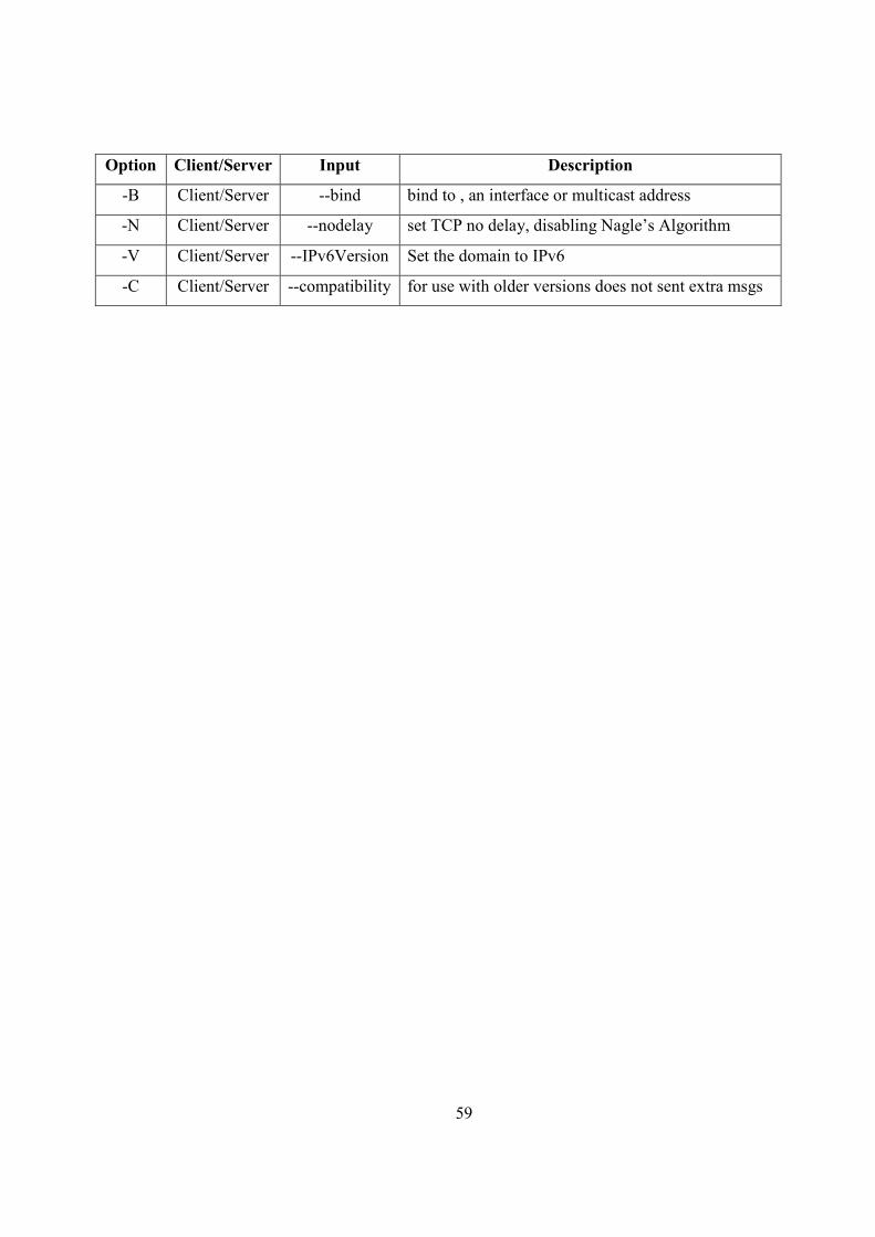
59
Option Client/Server Input Description
-B Client/Server --bind bind to , an interface or multicast address
-N Client/Server --nodelay set TCP no delay, disabling Nagle’s Algorithm
-V Client/Server --IPv6Version Set the domain to IPv6
-C Client/Server --compatibility for use with older versions does not sent extra msgs
60
Appendix D - #etPerf Commands
NetPerf is a network performance tool developed in Visual C++. NetPerf supports both
Windows and Linux operating systems. NetPerf supports both Command Line Interface and
Graphical User Interface. We preferred to use Command Line Interface. NetPerf is an open
source tool which can be easily downloaded and installed. NetPerf supports performance
measurement of many different protocols including protocols of TCP stack and SS7 stack. Open
SS7 community has tailored NetPerf to measure performance of Open SS7 stack. The accuracy
of performance measurement by NetPerf is depicted to be 99% while measuring throughput of
TCP stream in [19].
NetPerf is client-server architecture with netperf running in client and netserver running on
server. The two main performance methods are the bulk data transfer and request-response
measurement. Basically NetPerf carries out the test for 10 seconds and find the average value of
throughput or latency created in the network with the test data. NetPerf creates eight threads to
control, monitor, send data, receive data and create log [19]. The threads are prioritized in the
accordance their importance. The control thread creates 3 other threads, namely “TCP”, “UDP”
and “NTP”. The UDP thread creates “filewrite”, “scheduler”, “statcalc” and “main window”.
• Control thread: This is the dominant thread and controls the entire flow by
creating other required threads and handling events that occur throughout the
send-receive process.
• TCP thread: The TCP thread does the initial connection between client and server.
This is a connection oriented implying the acknowledgement of every packet sent.
The main data packet is not sent through TCP as the time required for TCP is
more compared to UDP transmission.
• NTP thread: NTP, Network time protocol is used to record all the timing events.
The traditional operating system clock drifts from accuracy of about 1 second a
day. The performance measurement is highly accurate process and needs an
accurate time stamping and hence NTP is used which calibrates itself with the
reference clock to stay with error less than 0.5 millisecond.
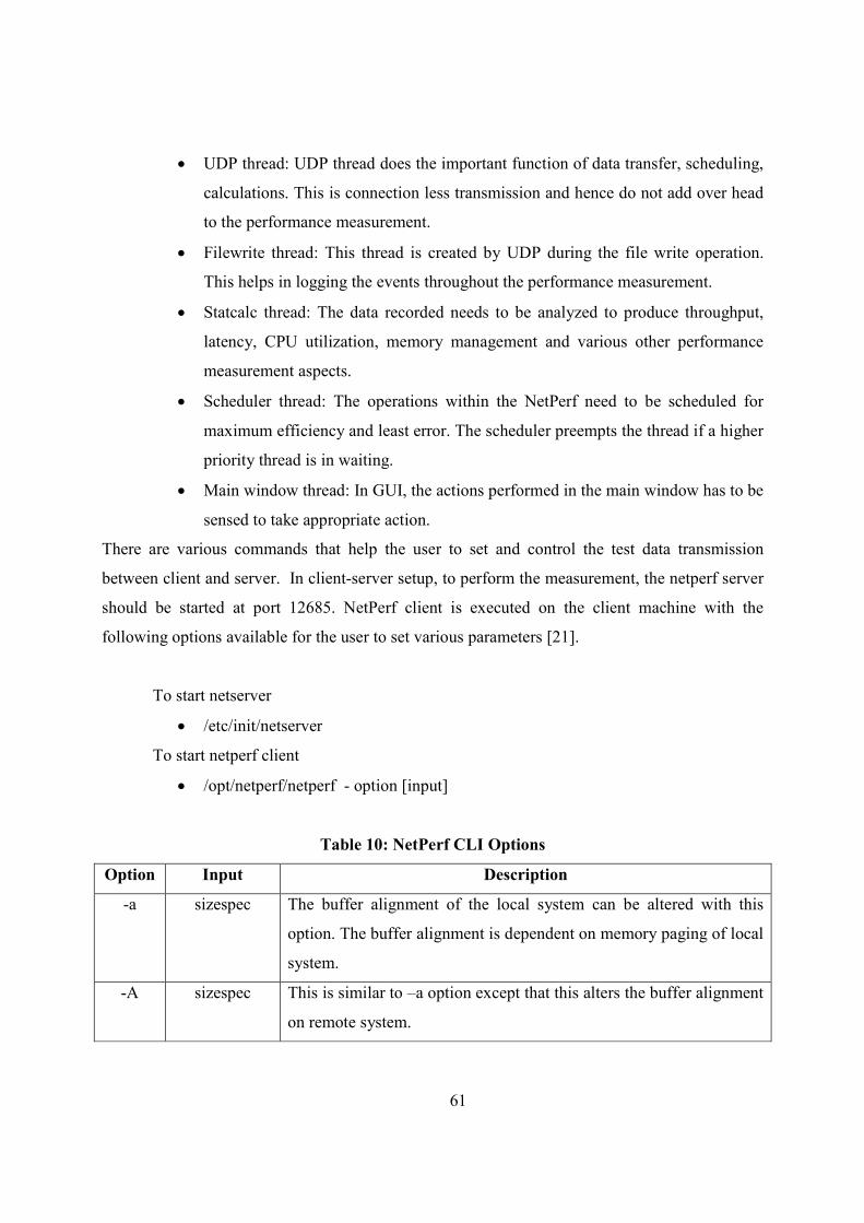
61
• UDP thread: UDP thread does the important function of data transfer, scheduling,
calculations. This is connection less transmission and hence do not add over head
to the performance measurement.
• Filewrite thread: This thread is created by UDP during the file write operation.
This helps in logging the events throughout the performance measurement.
• Statcalc thread: The data recorded needs to be analyzed to produce throughput,
latency, CPU utilization, memory management and various other performance
measurement aspects.
• Scheduler thread: The operations within the NetPerf need to be scheduled for
maximum efficiency and least error. The scheduler preempts the thread if a higher
priority thread is in waiting.
• Main window thread: In GUI, the actions performed in the main window has to be
sensed to take appropriate action.
There are various commands that help the user to set and control the test data transmission
between client and server. In client-server setup, to perform the measurement, the netperf server
should be started at port 12685. NetPerf client is executed on the client machine with the
following options available for the user to set various parameters [21].
To start netserver
• /etc/init/netserver
To start netperf client
• /opt/netperf/netperf - option [input]
Table 10: #etPerf CLI Options
Option Input Description
-a sizespec The buffer alignment of the local system can be altered with this
option. The buffer alignment is dependent on memory paging of local
system.
-A sizespec This is similar to –a option except that this alters the buffer alignment
on remote system.
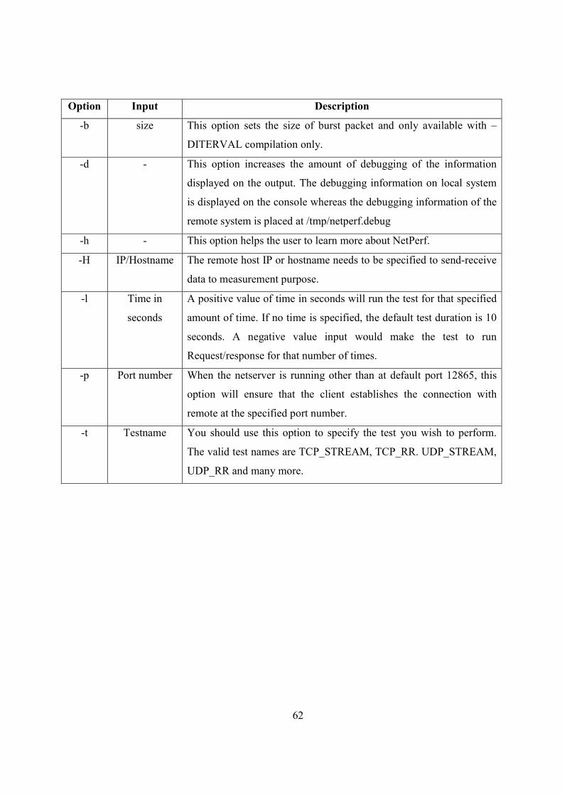
62
Option Input Description
-b size This option sets the size of burst packet and only available with –
DITERVAL compilation only.
-d - This option increases the amount of debugging of the information
displayed on the output. The debugging information on local system
is displayed on the console whereas the debugging information of the
remote system is placed at /tmp/netperf.debug
-h - This option helps the user to learn more about NetPerf.
-H IP/Hostname The remote host IP or hostname needs to be specified to send-receive
data to measurement purpose.
-l Time in
seconds
A positive value of time in seconds will run the test for that specified
amount of time. If no time is specified, the default test duration is 10
seconds. A negative value input would make the test to run
Request/response for that number of times.
-p Port number When the netserver is running other than at default port 12865, this
option will ensure that the client establishes the connection with
remote at the specified port number.
-t Testname You should use this option to specify the test you wish to perform.
The valid test names are TCP_STREAM, TCP_RR. UDP_STREAM,
UDP_RR and many more.