Embed Size (px)
Citation preview
Institut für Angewandte Physik
Proton LINAC for the Frankfurt Neutron Source FRANZ
International Topical Meeting on Nuclear Research
Applications and Utilization of Accelerators
4-8 May 2009
Vienna, Austria
Oliver Meusel
- IAEA -
Institut für Angewandte PhysikMotivation
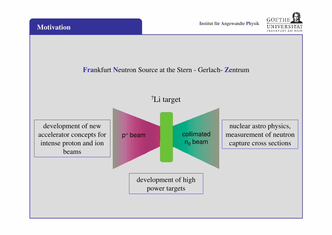
Frankfurt Neutron Source at the Stern - Gerlach- Zentrum
nuclear astro physics,
measurement of neutron
capture cross sections
development of high
power targets
development of new
accelerator concepts for
intense proton and ion
beams
collimated
n0 beamp+ beam
7Li target
Institut für Angewandte Physik
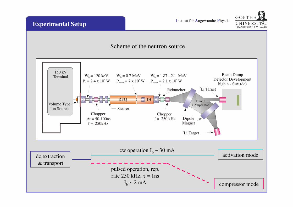
dc extraction
& transport
compressor mode
pulsed operation, rep.
rate 250 kHz, τ = 1ns
Ib ~ 2 mA
activation modecw operation Ib ~ 30 mA
Experimental Setup
W = 120 keV
P = 2.4 x 10 Wb
b
4
Chopper f = 250 kHz
Steerer
Beam DumpDetector Development
high n - flux (dc)7Li Target
BunchCompressor
W = 1.87 - 2.1 MeVb
P = 2.1 x 10 Wb,max
4
DipoleMagnet
IH
W = 0.7 MeVb
P = 7 x 10 Wb,max
3
Chopper
t = 50-100nsf = 250kHz
∆
Volume TypeIon Source
150 kVTerminal
Rebuncher
7Li Target
Scheme of the neutron source
Institut für Angewandte PhysikCompressor Mode
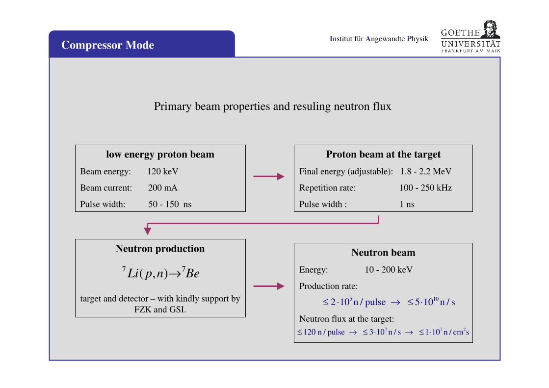
Neutron beam
Energy: 10 - 200 keV
Production rate:
Neutron flux at the target:
Neutron production
target and detector – with kindly support by
FZK and GSI.
low energy proton beam
Beam energy: 120 keV
Beam current: 200 mA
Pulse width: 50 - 150 ns
7 7Li p n Be( , )→
Proton beam at the target
Final energy (adjustable): 1.8 - 2.2 MeV
Repetition rate: 100 - 250 kHz
Pulse width : 1 ns
≤ ⋅ → ≤ ⋅2 10 5 105 10n / pulse n / s
≤ → ≤ ⋅ → ≤ ⋅120 3 1 n / pulse 10 n / s 10 n / cm s7 7 2
Primary beam properties and resuling neutron flux
Institut für Angewandte PhysikIon Source
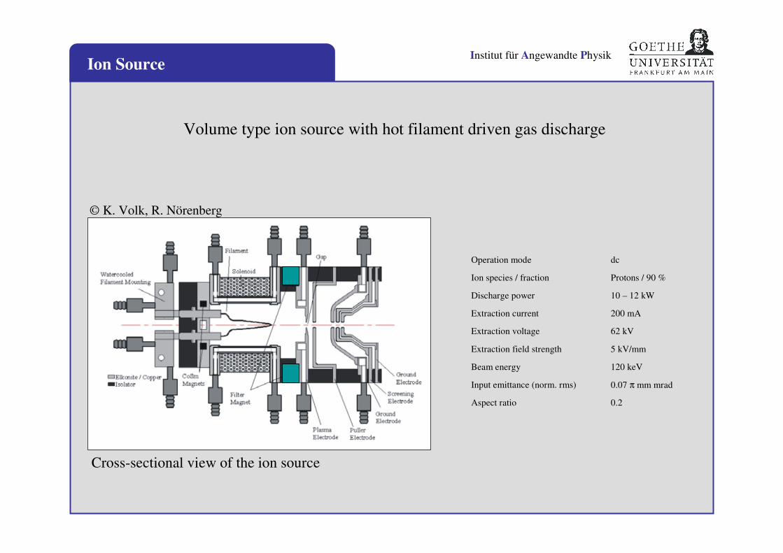
Volume type ion source with hot filament driven gas discharge
© K. Volk, R. Nörenberg
Cross-sectional view of the ion source
Operation mode dc
Ion species / fraction Protons / 90 %
Discharge power 10 – 12 kW
Extraction current 200 mA
Extraction voltage 62 kV
Extraction field strength 5 kV/mm
Beam energy 120 keV
Input emittance (norm. rms) 0.07 π mm mrad
Aspect ratio 0.2
Institut für Angewandte Physik
pm
eUv
2|| =
2/3
0 24
1
U
I
q
AK ⋅=
πε
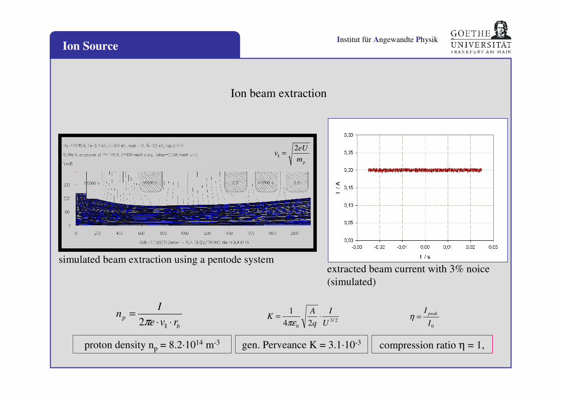
compression ratio η = 1,
b
prve
In
⋅⋅=
||2π0I
I peak=η
proton density np = 8.2·1014 m-3 gen. Perveance K = 3.1·10-3
simulated beam extraction using a pentode systemextracted beam current with 3% noice
(simulated)
Ion Source
Ion beam extraction
Institut für Angewandte Physik
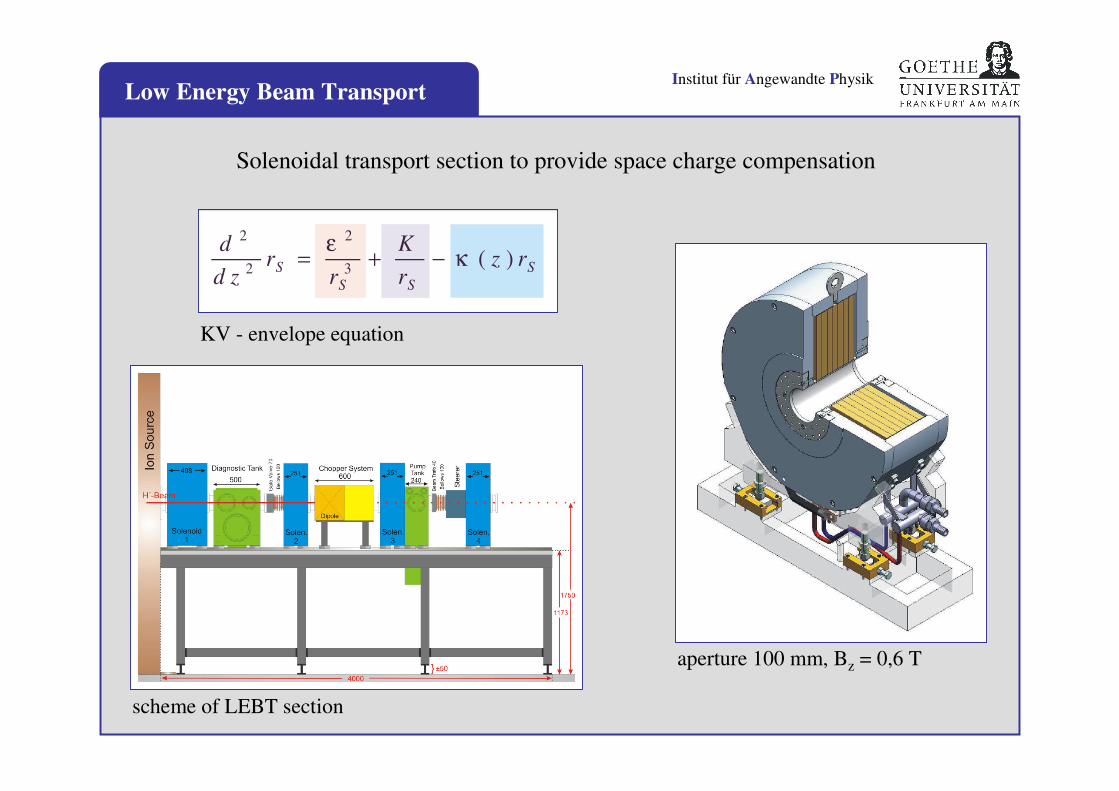
aperture 100 mm, Bz = 0,6 T
KV - envelope equation
d
d zr
r
K
rz rS
S S
S
2
2
2
3= + −
εκ ( )
scheme of LEBT section
Low Energy Beam Transport
Solenoidal transport section to provide space charge compensation
Institut für Angewandte Physik
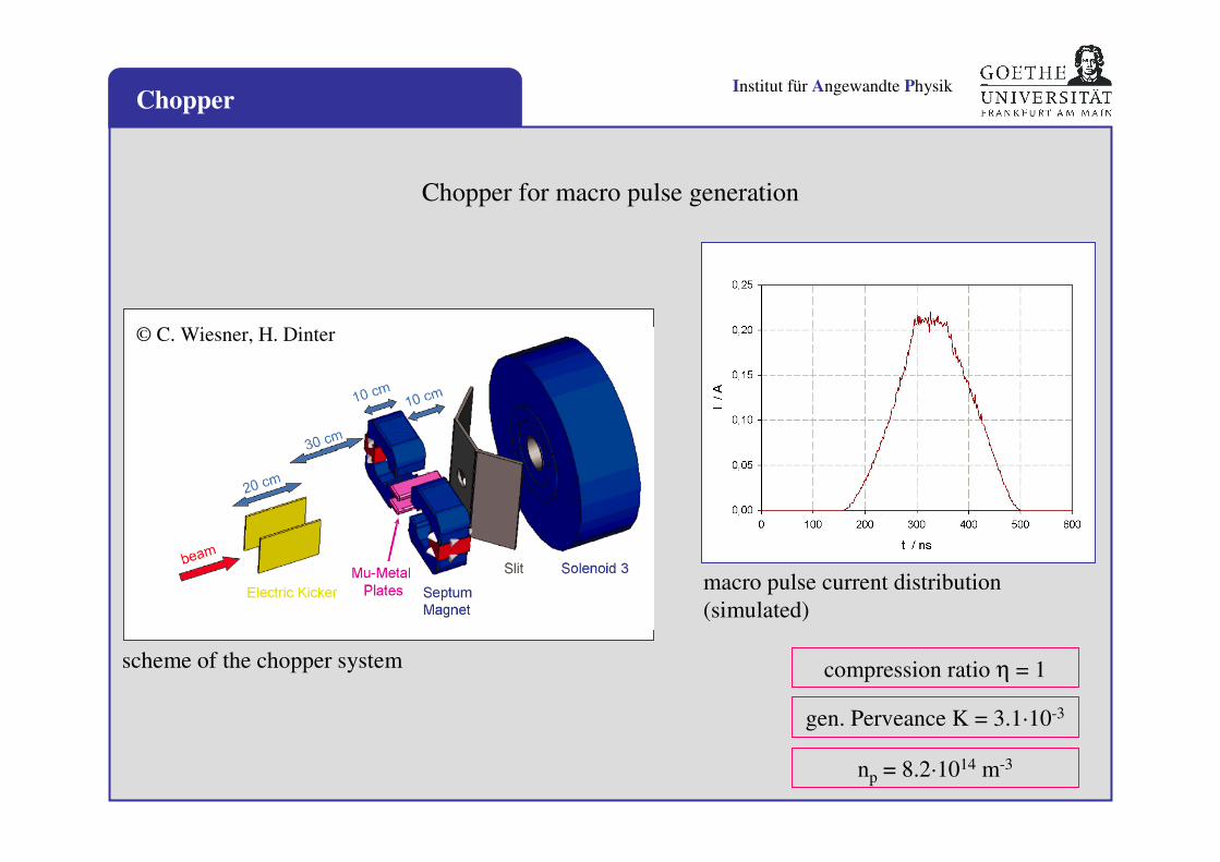
macro pulse current distribution
(simulated)
compression ratio η = 1
np = 8.2·1014 m-3
gen. Perveance K = 3.1·10-3
scheme of the chopper system
© C. Wiesner, H. Dinter
Chopper for macro pulse generation
Chopper
Institut für Angewandte Physik
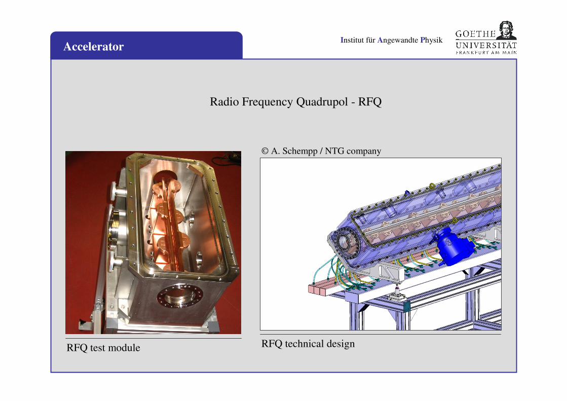
RFQ test module RFQ technical design
© A. Schempp / NTG company
Accelerator
Radio Frequency Quadrupol - RFQ
Institut für Angewandte Physik
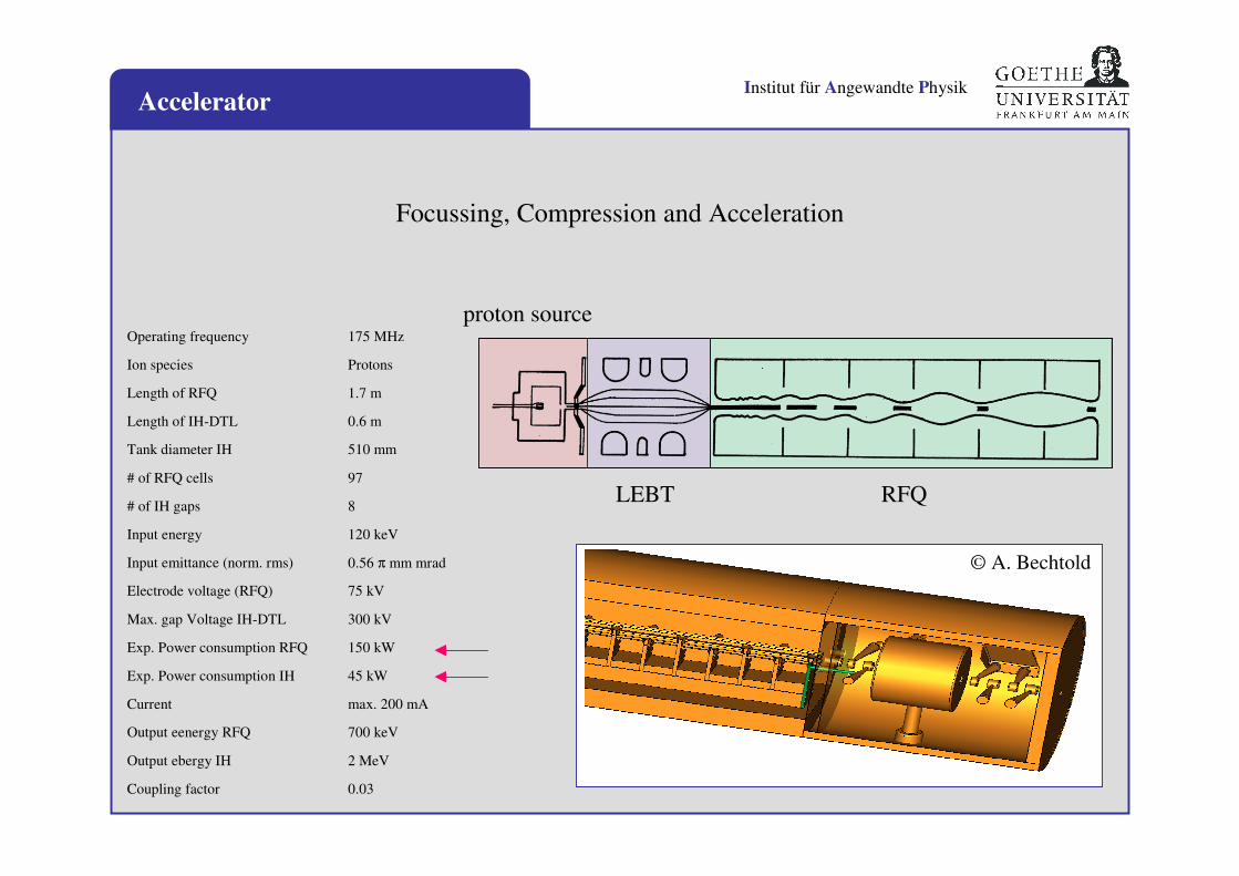
proton source
LEBT RFQ
Accelerator
Operating frequency 175 MHz
Ion species Protons
Length of RFQ 1.7 m
Length of IH-DTL 0.6 m
Tank diameter IH 510 mm
# of RFQ cells 97
# of IH gaps 8
Input energy 120 keV
Input emittance (norm. rms) 0.56 π mm mrad
Electrode voltage (RFQ) 75 kV
Max. gap Voltage IH-DTL 300 kV
Exp. Power consumption RFQ 150 kW
Exp. Power consumption IH 45 kW
Current max. 200 mA
Output eenergy RFQ 700 keV
Output ebergy IH 2 MeV
Coupling factor 0.03
Focussing, Compression and Acceleration
© A. Bechtold
Institut für Angewandte PhysikAccelerator
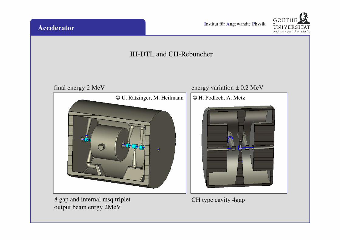
8 gap and internal msq triplet
output beam enrgy 2MeV CH type cavity 4gap
final energy 2 MeV energy variation ± 0.2 MeV
© H. Podlech, A. Metz© U. Ratzinger, M. Heilmann
IH-DTL and CH-Rebuncher
Institut für Angewandte Physik
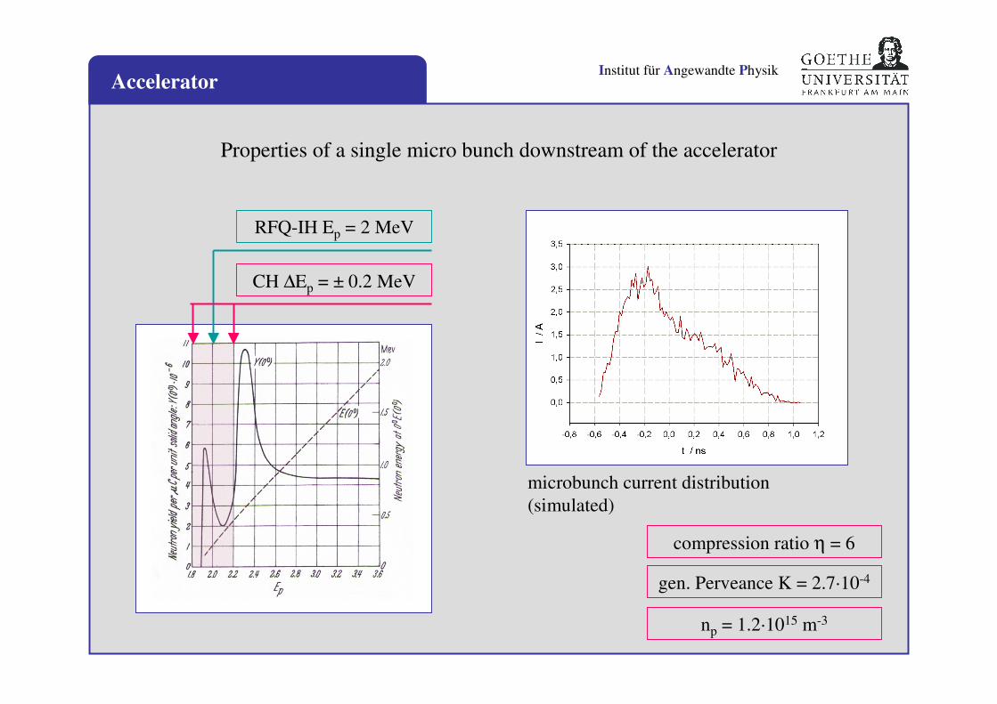
CH ∆Ep = ± 0.2 MeV
RFQ-IH Ep = 2 MeV
microbunch current distribution
(simulated)
compression ratio η = 6
np = 1.2·1015 m-3
gen. Perveance K = 2.7·10-4
Accelerator
Properties of a single micro bunch downstream of the accelerator
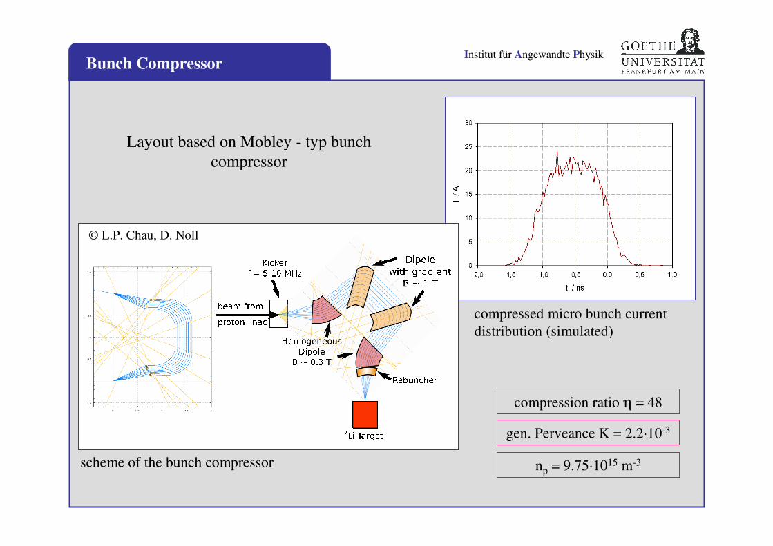
Institut für Angewandte PhysikBunch Compressor
compressed micro bunch current
distribution (simulated)
compression ratio η = 48
np = 9.75·1015 m-3
gen. Perveance K = 2.2·10-3
© L.P. Chau, D. Noll
scheme of the bunch compressor
Layout based on Mobley - typ bunch
compressor
Institut für Angewandte Physik
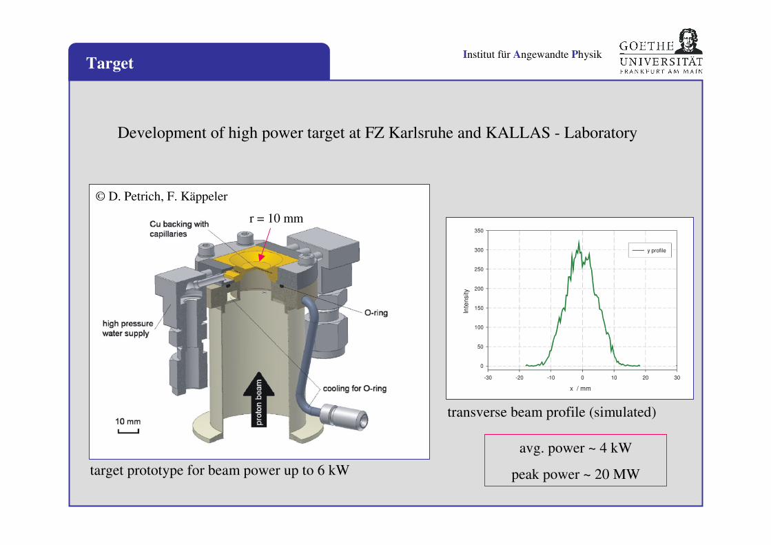
r = 10 mm
© D. Petrich, F. Käppeler
target prototype for beam power up to 6 kW
Target
x / mm
-30 -20 -10 0 10 20 30
Inte
nsity
0
50
100
150
200
250
300
350
y profile
transverse beam profile (simulated)
Development of high power target at FZ Karlsruhe and KALLAS - Laboratory
avg. power ~ 4 kW
peak power ~ 20 MW
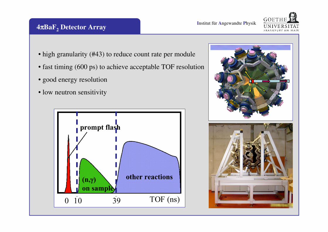
Institut für Angewandte Physik4ππππBaF2 Detector Array
• high granularity (#43) to reduce count rate per module
• fast timing (600 ps) to achieve acceptable TOF resolution
• good energy resolution
• low neutron sensitivity
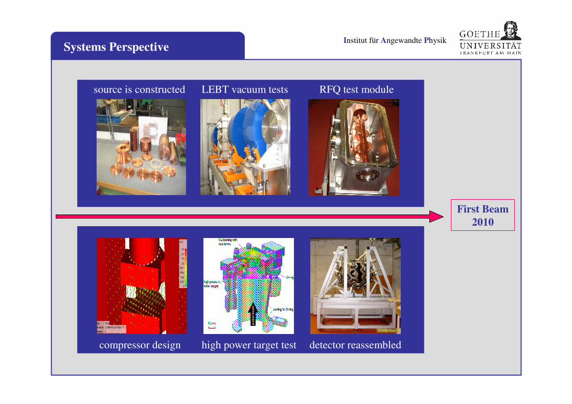
Institut für Angewandte PhysikSystems Perspective
LEBT vacuum tests RFQ test module
compressor design high power target test detector reassembled
source is constructed
First Beam
2010
Institut für Angewandte Physik
Thank you for your attention.
on behalf of:
LINAC-AG http://linac.physik.uni-frankfurt.de/
AG-Schempp http://iaprfq.physik.uni-frankfurt.de/
NNP-AG http://nnp.physik.uni-frankfurt.de
FZK / GSI / IAEA
acknowledgment:
A. Bechtold, L.P. Chau, M. Heilmann H. Podlech, U. Ratzinger, A. Schempp, C. Wiesner, S. Schmidt, K. Volk / IAP, Goethe University Frankfurt
M. Heil, R. Plag, R. Reifarth / GSI, Darmstadt
K. Stiebing, J. Stroth / IKF, Goethe University Frankfurt
F. Käppeler, D. Petrich / IKF, FZ Karlsruhe