Embed Size (px)
Citation preview

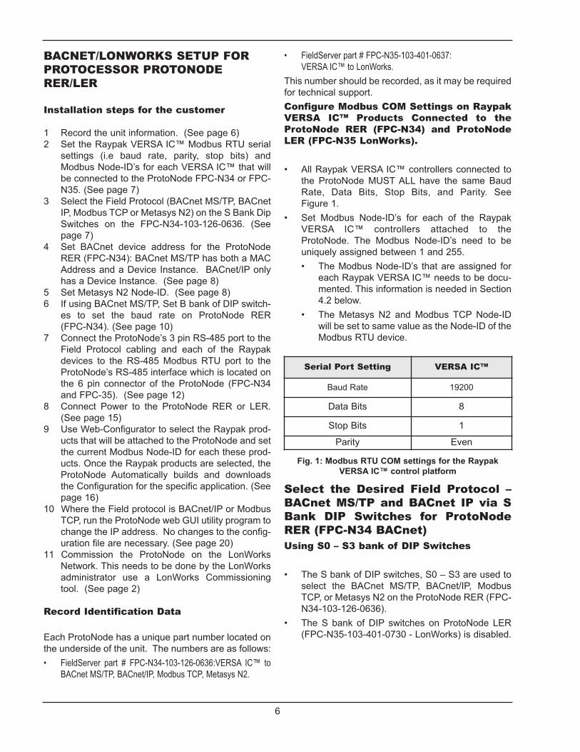
INSTALLATION & OPERATINGINSTRUCTIONS
Catalog No. 5000.73 Effective: 03-06-13 Replaces: NEW P/N 241515 Rev. 1
ProtoNode RER andProtoNode LER
For Interfacing Raypak heating products equipped with the VERSA IC™ control platform to BuildingAutomation Systems: BACnet MS/TP, BACnet IP, Modbus TCP, Metasys N2, and LonWorks

2
THIS PAGE INTENTIONALLY LEFT BLANK

3
Table of ContentsIntroduction..........................................................................................................................5BTL Mark – BACnet Testing Laboratory.................................................................................................................................................5LonMark Certification .............................................................................................................................................................................5BACnet/LonWorks Setup for ProtoCessor ProtoNode RER/LER .........................................6Installation steps for the customer .........................................................................................................................................................6Record Identification Data ......................................................................................................................................................................6Configure Modbus COM Settings on Raypak VERSA IC™ Products Connected to the ProtoNode RER (FPC-N34)and ProtoNode LER (FPC-N35 LonWorks) ...........................................................................................................................................6Select the Desired Field Protocol – BACnet MS/TP and BACnet IP via S Bank DIP Switches ............................................................6Using S0 – S3 bank of DIP Switches.....................................................................................................................................................6Set BACnet MS/TP, BACnet/IP, Metasys N2, and Modbus TCP; Device Instance (BACnet), Node-ID (N2 and Modbus TCP)and MAC Address for BACnet MS/TP on ProtoNode RER (FPC-N34) .................................................................................................7Setting the Device Instance (Node-ID) for BACnet MS/TP and BACnet/IP on ProtoNode RER (FPC-N34 BACnet)...........................7Setting the Node-ID for Metasys N2 and Modbus TCP on ProtoNode RER (FPC-N34 Metasys N2) ..................................................7Setting the MAC Address for BACnet MS/TP for the ProtoNode RER (FPC-N34 BACnet) ..................................................................7Set Baud Field RS-485 Baud Rate for BACnet MS/TP on ProtoNode RER (FPC-N34 BACnet) .........................................................8Setting the Serial Baud Rate (DIP Switch B0 – B3) for BACnet MS/TP................................................................................................8Interfacing the ProtoNode to Raypak Products .................................................................9ProtoNode RER (FPC-N34) and LER (FPC-N35) showing connection ports........................................................................................9Wiring Connections to ProtoNode RER (FPC-N34 BACnet) and ProtoNode LER (FPC-N35 LonWorks) ............................................10Connecting the VERSA IC™ Modbus port to the ProtoNode’s Phoenix 6 pin connector......................................................................11Wiring the ProtoNode RER to RS-485 Field Protocol (BACnet MS/TP or Metasys N2) .......................................................................12Wiring the ProtoNode LER (FPC-N35) Field Port to a LonWorks network ...........................................................................................12Power-Up the ProtoNode RER (FPC-N34 BACnet) or ProtoNode LER (FPC-N35 LonWorks) ............................................................13Connect to the ProtoNode’s Web Configurator to Setup the Raypak products (Profiles)connected to the ProtoNode RER or LER ...........................................................................13Connect the PC to the ProtoNode via the Ethernet port........................................................................................................................13Configure Profiles in the ProtoNode’s Web Configurator.......................................................................................................................14Selecting the Raypak profiles that will be connected the ProtoNode ....................................................................................................14Changing BN_Node_Offset via the ProtoNode’s Web Configurator ......................................................................................................16Set IP Address for BACnet/IP via GUI ...................................................................................................................................................17Commissioning the ProtoNode LER on a LonWorks network ............................................18Commissioning the ProtoNode LER on a LonWorks network ...............................................................................................................18Instructions to Upload XIF File From the ProtoNode LER Using FS GUI Web Server .........................................................................18Chipkin Automation’s CAS BACnet explorer for validating the ProtoNode in the field ....19Downloading Chipkin Automation’s CAS Explorer and Requesting an Activation Key..........................................................................19CAS BACnet Setup ................................................................................................................................................................................20CAS BACnet MS/TP Setup ....................................................................................................................................................................20CAS BACnet BACnet/IP Setup ..............................................................................................................................................................20Appendix A. Troubleshooting ..............................................................................................20Appendix A.1. Check Wiring and Settings .............................................................................................................................................20Appendix A.2. Take Diagnostic Capture With the FieldServer Utilities ..................................................................................................20Appendix A.3. Setting the Network Number for BACnet IP ...................................................................................................................22Appendix A.4. LED Diagnostics for Modbus RTU Communications between the ProtoNode and Raypak VERSA IC™ IC™.............22A.5.1 ProtoNode RER and LER LEDs ..................................................................................................................................................22Appendix B. Vendor Information .........................................................................................23Appendix B.1. Raypak VERSA IC™ Modbus RTU Mappings to BACnet MS/TP, BACnet/IP, Metasys N2, and LonWorks ................23Appendix B.2. Address DIP Switch Settings ..........................................................................................................................................28Appendix C. Reference ........................................................................................................32Appendix C.1. Specifications..................................................................................................................................................................32Appendix C.1.1 Compliance with UL Regulations..................................................................................................................................32Appendix D. Limited 2 year Warranty .................................................................................33

4
Table of Contents
Figure 1: Modbus RTU COM settings for the Raypak VERSA IC™ control platform ......................................6Figure 2: S0 – S3 DIP Switches .......................................................................................................................6Figure 3: A0 – A7 DIP Switches........................................................................................................................7Figure 4: B0 – B3 DIP Switches .......................................................................................................................8Figure 5: ProtoNode BACnet RER (left BACnet) and ProtoNode LER (right LonWorks) ................................9Figure 6: Power and RS485 pin outs................................................................................................................10Figure 7: VERSA IC™ Modbus RS485 pin outs to the ProtoNode’s Modbus port ..........................................11Figure 8: Connection from ProtoNode to RS-485 Field Protocol –BACnet MS/TP..........................................12Figure 9: End-of-line termination on from ProtoNode to RS-485 Field Protocol – BACnet MS/TP..................12Figure 10: Power pin outs to the ProtoNode ....................................................................................................13Figure 11: Ethernet port location of ProtoNode ................................................................................................13Figure 12: Web Configurator showing the active profiles to select from ..........................................................14Figure 13: Web Configurator showing a profile selected.................................................................................15Figure 14: Web Configurator showing a completed profile added ..................................................................15Figure 15: Web Configurator showing completed profiles added....................................................................16Figure 16: Change to BN_Node_Offset to set Device Instance ......................................................................16Figure 17: Default FS Web GUI Landing Page ...............................................................................................17Figure 18: Changing IP address via FST Web GUI.........................................................................................17Figure 19: Sample of Fserver.XIF file being generated....................................................................................18

5
Introduction
ProtoNode is an external, high performance BuildingAutomation multi-protocol gateway that is preconfig-ured to automatically communicate between Raypakheating products equipped with the VERSA IC™ con-trol platform to various building automation protocols.These protocols include BACnet MS/TP, BACnet/IP,Modbus TCP, Metasys N2, and LonWorks.
• Raypak supported products: VERSA IC™ control platform
Through the ProtoNode Web GUI Configurator, theuser selects how many VERSA IC™ are connected tothe ProtoNode as well as sets the Modbus Node-ID foreach the VERSA IC™. Once the Raypak products areselected, the ProtoNode Automatically builds anddownloads the Configuration for the desired protocol.
The total number of VERSA IC™ attached to the•ProtoNode RER (FPC-N34) cannot exceed 1400 Modbus registers for BACnet MS/TP, BACnet/IP. Modbus TCP or Metasys N2. The total number of VERSA IC™ attached to the •ProtoNode LER (FPC-N35) cannot exceed 1000 Modbus registers for LonWorks.
This document provides the necessary information tofacilitate installation of the ProtoNode.
BTL Mark – BACnet TestingLaboratory
The BTL Mark on the ProtoNodeRER is a symbol that indicatesthat a product has passed aseries of rigorous tests conduct-ed by an independent laboratorywhich verifies that the productcorrectly implements theBACnet features claimed in the listing. The mark is asymbol of a high-quality BACnet product. Go tohttp://www.bacnetinternational.net/btl/ for more infor-mation about the BACnet Testing Laboratory.
BoilerSystem
TotalModbusRegisters
Supporting
VERSA IC™ 165
1 VERSA IC™ hasup to 4 boilersprogrammed
in the ProtoNode
LonMark Certification
LonMark International is the recognized authority forcertification, education, and promotion of interoperabil-ity standards for the benefit of manufacturers,integrators and end users. LonMark International hasdeveloped extensive product certification standardsand tests to provide the integrator and user with confi-dence that products from multiple manufacturersutilizing LonMark devices work together. FieldServerTechnologies has more LonMark Certified gatewaysthan any other gateway manufacturer, including theProtoCessor, ProtoCarrier and ProtoNode for OEMapplications and the full featured, configurable gate-ways.
6
BACNET/LONWORKS SETUP FORPROTOCESSOR PROTONODERER/LER
Installation steps for the customer
Record the unit information. (See page 6)1Set the Raypak VERSA IC™ Modbus RTU serial2settings (i.e baud rate, parity, stop bits) andModbus Node-ID’s for each VERSA IC™ that willbe connected to the ProtoNode FPC-N34 or FPC-N35. (See page 7)Select the Field Protocol (BACnet MS/TP, BACnet3IP, Modbus TCP or Metasys N2) on the S Bank DipSwitches on the FPC-N34-103-126-0636. (Seepage 7)Set BACnet device address for the ProtoNode4RER (FPC-N34): BACnet MS/TP has both a MACAddress and a Device Instance. BACnet/IP onlyhas a Device Instance. (See page 8)Set Metasys N2 Node-ID. (See page 8)5If using BACnet MS/TP, Set B bank of DIP switch-6es to set the baud rate on ProtoNode RER(FPC-N34). (See page 10) Connect the ProtoNode’s 3 pin RS-485 port to the7Field Protocol cabling and each of the Raypakdevices to the RS-485 Modbus RTU port to theProtoNode’s RS-485 interface which is located onthe 6 pin connector of the ProtoNode (FPC-N34and FPC-35). (See page 12) Connect Power to the ProtoNode RER or LER. 8(See page 15)Use Web-Configurator to select the Raypak prod-9ucts that will be attached to the ProtoNode and setthe current Modbus Node-ID for each these prod-ucts. Once the Raypak products are selected, theProtoNode Automatically builds and downloadsthe Configuration for the specific application. (Seepage 16) Where the Field protocol is BACnet/IP or Modbus10TCP, run the ProtoNode web GUI utility program tochange the IP address. No changes to the config-uration file are necessary. (See page 20)Commission the ProtoNode on the LonWorks11Network. This needs to be done by the LonWorksadministrator use a LonWorks Commissioningtool. (See page 2)
Record Identification Data
Each ProtoNode has a unique part number located onthe underside of the unit. The numbers are as follows:
FieldServer part # FPC-N34-103-126-0636:VERSA IC™ to•BACnet MS/TP, BACnet/IP, Modbus TCP, Metasys N2.
FieldServer part # FPC-N35-103-401-0637: •VERSA IC™ to LonWorks.
This number should be recorded, as it may be requiredfor technical support.Configure Modbus COM Settings on RaypakVERSA IC™ Products Connected to theProtoNode RER (FPC-N34) and ProtoNodeLER (FPC-N35 LonWorks).
All Raypak VERSA IC™ controllers connected to•the ProtoNode MUST ALL have the same BaudRate, Data Bits, Stop Bits, and Parity. SeeFigure 1. Set Modbus Node-ID’s for each of the Raypak•VERSA IC™ controllers attached to theProtoNode. The Modbus Node-ID’s need to beuniquely assigned between 1 and 255.
The Modbus Node-ID’s that are assigned for•each Raypak VERSA IC™ needs to be docu-mented. This information is needed in Section4.2 below. The Metasys N2 and Modbus TCP Node-ID•will be set to same value as the Node-ID of theModbus RTU device.
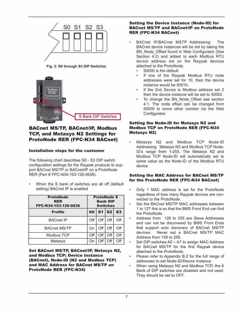
Select the Desired Field Protocol –BACnet MS/TP and BACnet IP via SBank DIP Switches for ProtoNodeRER (FPC-N34 BACnet)Using S0 – S3 bank of DIP Switches
The S bank of DIP switches, S0 – S3 are used to•select the BACnet MS/TP, BACnet/IP, ModbusTCP, or Metasys N2 on the ProtoNode RER (FPC-N34-103-126-0636).The S bank of DIP switches on ProtoNode LER•(FPC-N35-103-401-0730 - LonWorks) is disabled.
Serial Port Setting VERSA IC™
Baud Rate 19200
Data Bits 8
Stop Bits 1
Parity Even
Fig. 1: Modbus RTU COM settings for the RaypakVERSA IC™ control platform
7
BACnet MS/TP, BACnet/IP, ModbusTCP, and Metasys N2 Settings forProtoNode RER (FPC-N34 BACnet)
Installation steps for the customer
The following chart describes S0 - S3 DIP switchconfiguration settings for the Raypak products to sup-port BACnet MS/TP or BACnet/IP on a ProtoNodeRER (Part # FPC-N34-103-126-0636).
When the S bank of switches are all off (default•setting) BACnet IP is enabled
Set BACnet MS/TP, BACnet/IP, Metasys N2,and Modbus TCP; Device Instance(BACnet), Node-ID (N2 and Modbus TCP)and MAC Address for BACnet MS/TP onProtoNode RER (FPC-N34)
Setting the Device Instance (Node-ID) forBACnet MS/TP and BACnet/IP on ProtoNodeRER (FPC-N34 BACnet)
BACnet IP/BACnet MSTP Addressing: The•BACnet device instances will be set by taking theBN_Node_Offset found in Web Configurator (SeeSection 4.2) and added to each Modbus RTUdevice address set on the Raypak devicesattached to the ProtoNode.
50000 is the default•If one of the Raypak Modbus RTU node•addresses were set for 10, then the deviceinstance would be 50010. If the 2nd Device is Modbus address set 2•then the device instance will be set to 50002.To change the BN_Node_Offset see section•4.1. The node offset can be changed from50000 to some other number via the WebConfigurator.
Setting the Node-ID for Metasys N2 andModbus TCP on ProtoNode RER (FPC-N34Metasys N2)
Metasys N2 and Modbus TCP Node-ID•Addressing: Metasys N2 and Modbus TCP Node-ID’s range from 1-255. The Metasys N2 andModbus TCP Node-ID will automatically set tosame value as the Node-ID of the Modbus RTUdevice
Setting the MAC Address for BACnet MS/TPfor the ProtoNode RER (FPC-N34 BACnet)
Only 1 MAC address is set for the ProtoNode•regardless of how many Raypak devices are con-nected to the ProtoNode.Set the BACnet MS/TP MAC addresses between•1 to 127 this is so that the BMS Front End can findthe ProtoNode. Address from 128 to 255 are Slave Addresses•and can not be discovered by BMS Front Endsthat support auto discovery of BACnet MS/TPdevices. Never set a BACnet MS/TP MACAddress from 128 to 255. Set DIP switches A0 – A7 to assign MAC Address•for BACnet MS/TP for the first Raypak deviceattached to the ProtoNode.Please refer to Appendix B.2 for the full range of•addresses to set Node-ID/Device Instance. When using Metasys N2 and Modbus TCP, the A•Bank of DIP switches are disabled and not used.They should be set to OFF.
ProtoNodeRER
FPC-N34-103-126-0636
ProtoNode S Bank DIP Switches
Profile SO S1 S2 S3
BACnet IP Off Off Off Off
BACnet MS/TP On Off Off Off
Modbus TCP Off Off Off OffMetasys On Off Off Off
S Bank DIP Switches
Fig. 2: S0 through S3 DIP Switches

8
Set Baud Field RS-485 Baud Ratefor BACnet MS/TP on ProtoNodeRER (FPC-N34 BACnet)
Setting the Serial Baud Rate (DIP SwitchB0 – B3) for BACnet MS/TP
DIP Switches B0 – B3 can be used to set the seri-•al baud rate to match the baud rate provided bythe Building Management System for BACnetMS/TP. DIP Switches B0 – B3 are disabled on ProtoNode•LER (FPC-N35 LonWorks).The rate on the ProtoNode for Metasys is set for•9600. DIP Switches B0 – B3 are disabled forMetasys N2 on ProtoNode RER (FPC-N34).
Baud B0 B1 B2 B3
9600 On On On Off
19200 Off Off Off On
38400 On On Off On
57600 Off Off On On
76800 On Off On On
Fig. 4: B0 through B3 DIP Switches
Fig. 3: A0 through A7 DIP Switches
NOTE: When setting DIP switches, please ensurethat power to the board is OFF.
9
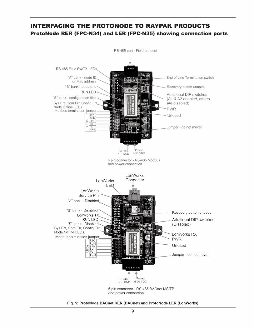
INTERFACING THE PROTONODE TO RAYPAK PRODUCTSProtoNode RER (FPC-N34) and LER (FPC-N35) showing connection ports
Fig. 5: ProtoNode BACnet RER (BACnet) and ProtoNode LER (LonWorks)

10
Wiring Connections to ProtoNode RER (FPC-N34 BACnet) andProtoNode LER (FPC-N35 LonWorks)
Fig. 6: Power and RS485 pin outs
Raypak Pin # ProtoNodePin
Assignment
MODBUS A + Pin 1 RS-485 +
MODBUS B - Pin 2 RS-485 -
MODBUS GND Pin 3 RS-485 GND
Power In (+) Pin 4 V +
Power In (-) Pin 5 V -
Frame Ground Pin 6 Frame GND

11
Connecting the VERSA IC™ Modbus port to the ProtoNode’sPhoenix 6 pin connector.
Connect VERSA IC™ Modbus pin A (RS485+) to the ProtoNode’s pin 1 (RS485+) on the Phoenix 6 pin connector. •Connect VERSA IC™ Modbus pin B (RS485-) to the ProtoNode’s pin 2 (RS485-) on the Phoenix 6 pin connector. •Connect VERSA IC™ Modbus pin GND (Ground) and the ProtoNode’s pin 3 (Signal Ground) on the Phoenix 6 pin connector.•
Fig. 7: VERSA IC™ Modbus RS485 pin outs to the ProtoNode’s Modbus port
12
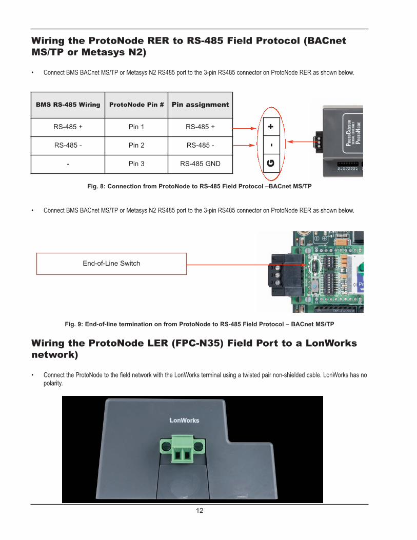
Wiring the ProtoNode RER to RS-485 Field Protocol (BACnetMS/TP or Metasys N2)
Connect BMS BACnet MS/TP or Metasys N2 RS485 port to the 3-pin RS485 connector on ProtoNode RER as shown below. •
Fig. 8: Connection from ProtoNode to RS-485 Field Protocol –BACnet MS/TP
BMS RS-485 Wiring ProtoNode Pin # Pin assignment
RS-485 + Pin 1 RS-485 +
RS-485 - Pin 2 RS-485 -
- Pin 3 RS-485 GND
+-
G
Connect BMS BACnet MS/TP or Metasys N2 RS485 port to the 3-pin RS485 connector on ProtoNode RER as shown below. •
Fig. 9: End-of-line termination on from ProtoNode to RS-485 Field Protocol – BACnet MS/TP
End-of-Line Switch
Wiring the ProtoNode LER (FPC-N35) Field Port to a LonWorksnetwork)
Connect the ProtoNode to the field network with the LonWorks terminal using a twisted pair non-shielded cable. LonWorks has no•polarity.
13
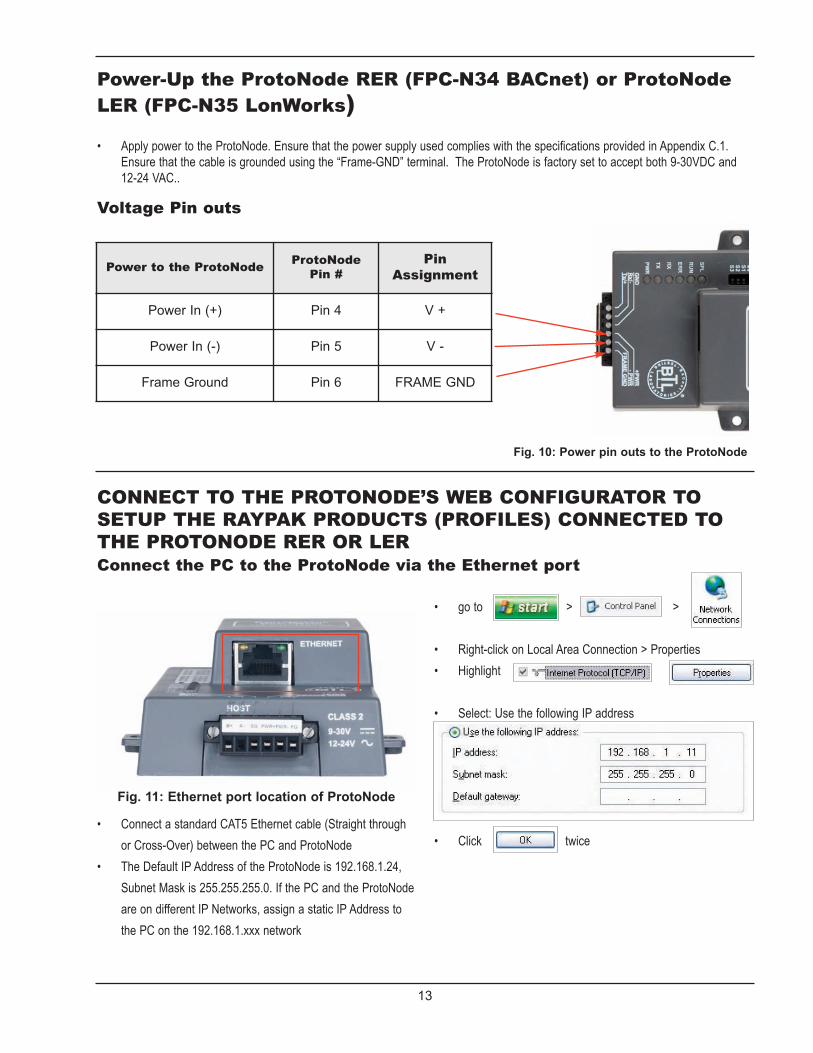
Power-Up the ProtoNode RER (FPC-N34 BACnet) or ProtoNodeLER (FPC-N35 LonWorks)
Fig. 10: Power pin outs to the ProtoNode
Power to the ProtoNodeProtoNode Pin #
PinAssignment
Power In (+) Pin 4 V +
Power In (-) Pin 5 V -
Frame Ground Pin 6 FRAME GND
Apply power to the ProtoNode. Ensure that the power supply used complies with the specifications provided in Appendix C.1.•Ensure that the cable is grounded using the “Frame-GND” terminal. The ProtoNode is factory set to accept both 9-30VDC and12-24 VAC..
Voltage Pin outs
CONNECT TO THE PROTONODE’S WEB CONFIGURATOR TOSETUP THE RAYPAK PRODUCTS (PROFILES) CONNECTED TOTHE PROTONODE RER OR LERConnect the PC to the ProtoNode via the Ethernet port
Fig. 11: Ethernet port location of ProtoNode
Connect a standard CAT5 Ethernet cable (Straight through•
or Cross-Over) between the PC and ProtoNode
The Default IP Address of the ProtoNode is 192.168.1.24,•
Subnet Mask is 255.255.255.0. If the PC and the ProtoNode
are on different IP Networks, assign a static IP Address to
the PC on the 192.168.1.xxx network
go to > > •
Right-click on Local Area Connection > Properties•
Highlight >•
Select: Use the following IP address•
Click twice •

14
Configure Profiles in the ProtoNode’s Web Configurator
Open PC web browser; enter the default IP address of the ProtoNode 192.168.1.24.•When the S bank of DIP switches are set for BACnet you will see all the Raypak Profiles supporting BACnet listed in the•Configurator. When the S bank is set for BACnet MS/TP, all Raypak profiles support BACnet MS/TP will appear. •
Selecting the Raypak profiles that will be connected theProtoNode
When you open the Web Configurator, you will see Active Profiles on the left side of the screen. There is a pull down box under•Current Profiles that will list all the profiles available to select from. To add an active profile to the ProtoNode, select Add under Active Profiles. For every Raypak product that will be added to the•ProtoNode, you will need to add the Active Profile (on the left of the screen) and the Modbus Node Address that the device is
assigned to.
Fig. 12: Web Configurator showing the active profiles to select from
Once the Profile and Modbus Node Address have been selected, press the Add button to add the Profile to be configured.•
15
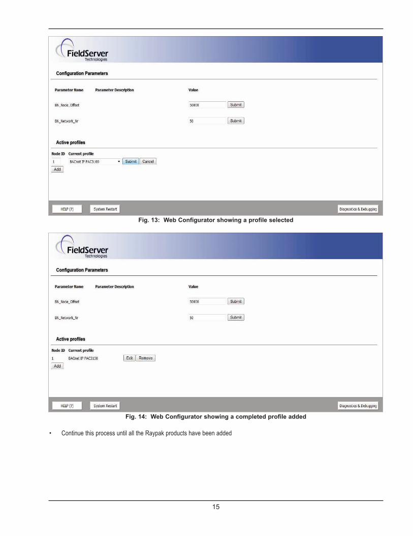
Fig. 13: Web Configurator showing a profile selected
Fig. 14: Web Configurator showing a completed profile added
Continue this process until all the Raypak products have been added •

16
Fig. 15: Web Configurator showing completed profiles added
Changing BN_Node_Offset via the ProtoNode’s WebConfigurator
The BACnet Device Instance is equal to the Modbus Node ID plus the BN_Node_Offset.•To change the BN_Node_offset, enter the new values for the off set in web configurator.•
Fig. 16: Change to BN_Node_Offset to set Device Instance
17
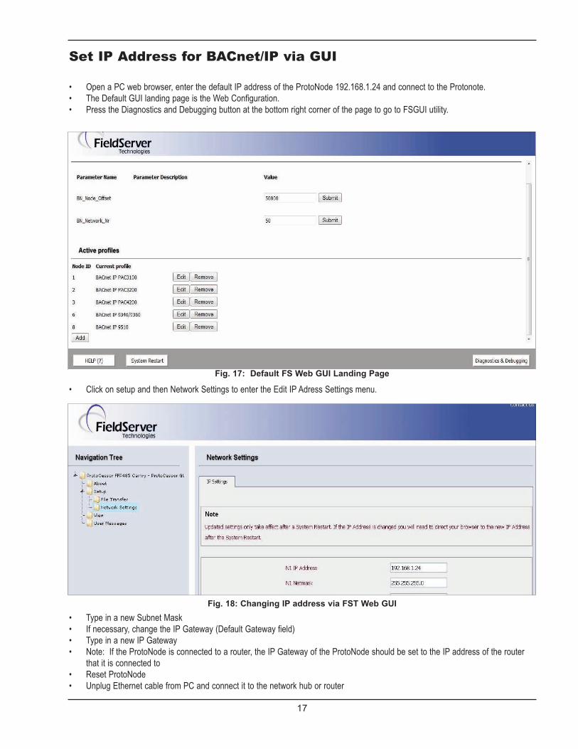
Set IP Address for BACnet/IP via GUI
Open a PC web browser, enter the default IP address of the ProtoNode 192.168.1.24 and connect to the Protonote.•The Default GUI landing page is the Web Configuration. •Press the Diagnostics and Debugging button at the bottom right corner of the page to go to FSGUI utility.•
Fig. 17: Default FS Web GUI Landing Page
Click on setup and then Network Settings to enter the Edit IP Adress Settings menu. •
Fig. 18: Changing IP address via FST Web GUIType in a new Subnet Mask •If necessary, change the IP Gateway (Default Gateway field)•Type in a new IP Gateway •Note: If the ProtoNode is connected to a router, the IP Gateway of the ProtoNode should be set to the IP address of the router•that it is connected toReset ProtoNode•Unplug Ethernet cable from PC and connect it to the network hub or router•

COMMISSIONING THEPROTONODE LER ON ALONWORKS NETWORK
Commissioning may only be per-formed by the LonWorksadministrator.
Commissioning the ProtoNode LERon a LonWorks net-work
To commission the ProtoNodeLER LonWorks port, insert asmall screwdriver in the commis-sioning hole on the face of theLER’s enclosure to access theService Pin. See the illustrationon the ProtoNode LER as to which way to toggle thescrew driver during commissioning.
If an XIF file is required, see steps•Section 4.1.1 to generate XIF
Instructions to Upload XIF FileFrom the ProtoNode LER UsingFS GUI Web Server
Connect a standard cat5 Ethernet cable between the PC•and ProtoNodeThe Default IP Address of the ProtoNode is 192.168.1.24,•Subnet Mask is 255.255.255.0. If the PC and the ProtoNodeare on different IP Networks, assign a static IP Address tothe PC on the 192.168.1.xxx network
•For Windows XP:
go to > > > •
Right-click on Local Area Connection > Properties•
Highlight >•
For Windows 7:
go to > > •
Right-click on Local Area Connection > Properties•
Highlight >•
18
For Windows XP and Windows 7, select: Use the following•
IP address
Click twice •
Open a web browser and go to the following address: IP•
address of ProtoCessor/fserver.xif
Example: 192.168.1.24/fserver.xif•
Download and save the file onto the PC.•
Fig. 19: Sample of Fserver.XIF file being generated

19
CHIPKIN AUTOMATION’S CAS BACNET EXPLORER FOR VALI-DATING THE PROTONODE IN THE FIELD
Chipkin Automation has extended to Raypak and their customers a free complementary 2 week fully functionalcopy of CAS BACnet Explorer that can be used to validate BACnet MS/TP and/or BACnet/IP communicationsof the ProtoNode in the field without having to have the BMS Integrator on site. A Serial or USB to RS-485converter is needed to test BACnet MS/TP.
Downloading Chipkin Automation’s CAS Explorer and Requesting anActivation Key
To request a 2 week complementary BACnet CAS key, go to http://app.chipkin.com/activation/twoweek/ and fill in all the informa-•tion. Enter Vendor Code “Raypak2012”. Once completed, the key will be sent to the email address that was submitted. From thisemail from Chipkin Automation, the long key will need to be copied and pasted into the CAS key activation page.
Go to Chipkin Automation’s web site, download, and install the CAS BACnet Explorer to your PC http://www.chipkin.com/techni-•cal-resources/cas-bacnet-explorer/. In the CAS Activation form, enter the email address and paste the CAS key that was sent from Chipkin Automation. Once com-•pleted, select Activation.

20
CAS BACnet Setup
These are the instructions to set CAS Explorer up forthe first time on BACnet MS/ST and BACnet/IP.
CAS BACnet MS/TP Setup
Using the Serial or USB to RS-485 converter, connect it to•your PC and the 3 Pin BACnet MS/TP connector on theProtoNode RER.In CAS Explorer, do the following:•
Click on settings•Check the BACnet MSTP box and uncheck the BACnet•IP and BACnet Ethernet boxes.Set the BACnet MSTP MAC address to 0.•Set the BACnet MSTP Baud Rate to 38400.•Click Ok.•On the bottom right-hand corner, make sure that the•BACnet MSTP box is green.Click on discover.•Check all 4 boxes.•Click Send.•
CAS BACnet BACnet/IP Setup
See Section 5.1 to set the IP address and subnet of the PC•that will be running the CAS Explorer.Connect a straight through or cross Ethernet cable from the•PC to the ProtoNode. In CAS Explorer, do the following:•
Click on settings•Check the BACnet IP box and uncheck the BACnet•MSTP and BACnet Ethernet boxes.In the “Select a Network Device” box, select the net-•work card of the PC by clicking on it.Click Ok.•On the bottom right-hand corner, make sure that the•BACnet IP box is green.Click on discover.•Check all 4 boxes.•Click Send.•
Appendix A. TrobleshootingAppendix A.1. check Wiring and Setitings
No COMS on Modbus RTU side. If Tx/Rx are not flashing•rapidly then there is a COM issue on the Modbus side andyou need to check the following things:
Visual observations of LEDs on ProtoNode. See•Appendix A.5Check baud rate, parity, data bits, stop bits•Check Modbus device address•Verify wiring•
Field COM problems.•
Visual observations of LEDs on ProtoNode. See•Appendix A.5Visual dipswitch settings (using correct baud rate and•device instance)Verify IP address setting•Verify wiring•
If the problem still exists, a Diagnostic Capture needs to be takenand sent to FieldServer. See Appendix A.2
Appendix A.2. Take DiagnosticCapture With the FieldServerUtilities
Once the Diagnostic Capture is complete, email it to sup-•[email protected]. The Diagnostic Capture will allow usto rapidly diagnose the problem.Make sure the FieldServer utilities are loaded on the PC.•http://fieldserver.com/techsupport/utility/utility.phpDisable any wireless Ethernet adapters on the PC/Laptop•Disable firewall and virus protection software if possible•Connect a standard cat5 Ethernet cable between the PC•
and the ProtoNode The Default IP Address of the ProtoNode is 192.168.1.24,•Subnet Mask is 255.255.255.0. If the PC and the ProtoNodeare on different IP Networks, assign a static IP Address tothe PC on the 192.168.1.xxx network
For Windows XP:
go to > > •
Right-click on Local Area Connection > Properties•
Highlight >•

21
For Windows 7:
go to > > •
Right-click on Local Area Connection > Properties•
Highlight >•
For Windows XP and Windows 7, select: Use the following•
IP address
Click twice •
Double click on the FST Diag Utility.•
Step 1: Select a Field Server IP Address.•
The IP address can be entered manually or selected by•
clicking on button 1 using
Type in the ProtoNode IP addressDefault IP Address is 192.168.1.24
Press here to retrieve the IP address.
Select a log type.
Press the Take Log button.
Locate where the log is saved onthe PC
the Utility.
Step 2: Take a Log•
Press the Take Log button. While the Utility runs a few DOS•
prompts will flash across the monitor. Don't click or type
anything in to these DOS prompts. This step may take a
few minutes depending on the chosen Log Type and com-
puter speed. When the Utility is finished you will be
presented with a log of events that have occurred.
Step 3: Send Log•
Click the “Send Log” button located near the bottom of the•
dialog. The following dialog should appear.
Push the ‘Locate Folder’ button to launch explorer and have•
it point directly at the correct folder. The file upload.zip must
be sent to [email protected].
Step 4: Close the Program •
Press the button when the log is completed •
22
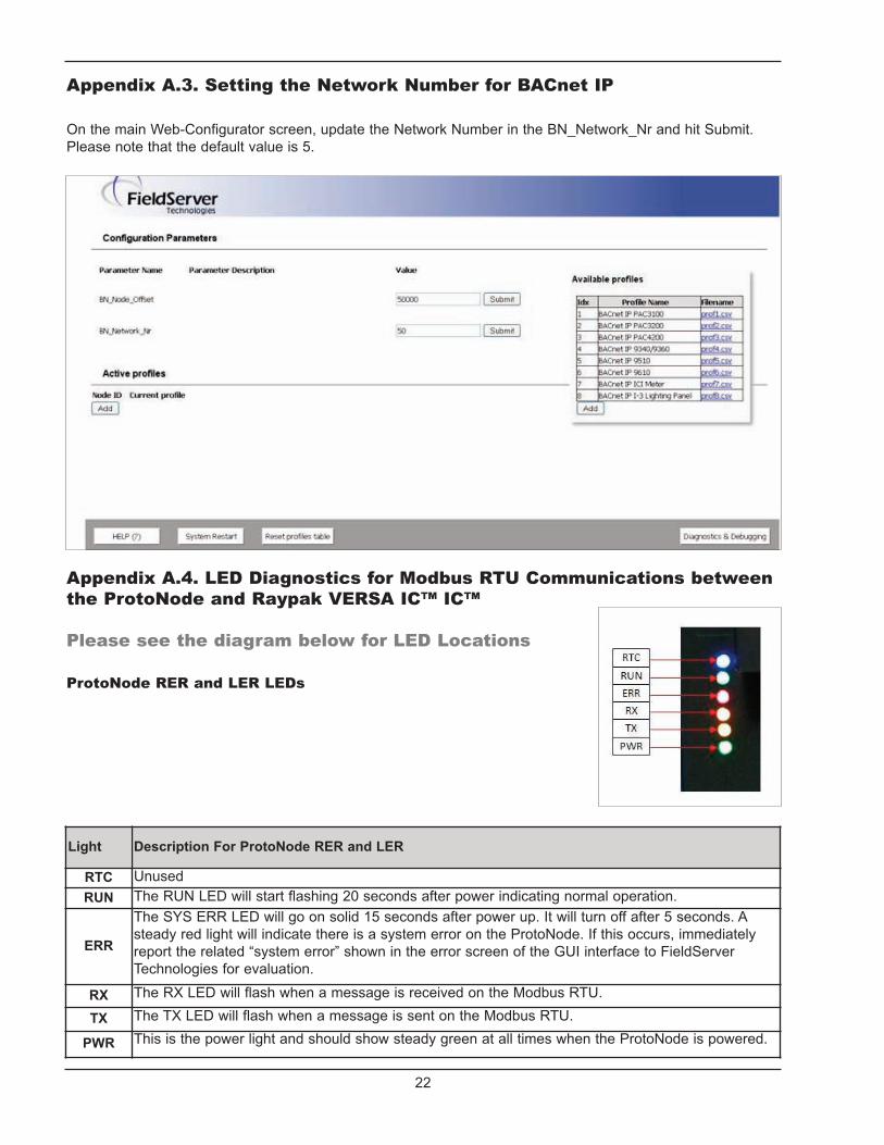
Appendix A.3. Setting the Network Number for BACnet IP
On the main Web-Configurator screen, update the Network Number in the BN_Network_Nr and hit Submit.Please note that the default value is 5.
Appendix A.4. LED Diagnostics for Modbus RTU Communications betweenthe ProtoNode and Raypak VERSA IC™ IC™
Please see the diagram below for LED Locations
ProtoNode RER and LER LEDs
Light Description For ProtoNode RER and LER
RTC UnusedRUN The RUN LED will start flashing 20 seconds after power indicating normal operation.
ERR
The SYS ERR LED will go on solid 15 seconds after power up. It will turn off after 5 seconds. Asteady red light will indicate there is a system error on the ProtoNode. If this occurs, immediatelyreport the related “system error” shown in the error screen of the GUI interface to FieldServerTechnologies for evaluation.
RX The RX LED will flash when a message is received on the Modbus RTU.
TX The TX LED will flash when a message is sent on the Modbus RTU.
PWR This is the power light and should show steady green at all times when the ProtoNode is powered.

23
Point NameBACnetObjectType
BACnetObject ID
N2DataType
N2PointAddress
Lon Name Lon SNVT
MODBUS AI 1 AI 1 nvoMODBUS_xxx SNVT_count_f
System Supply Temperature AI 2 AI 2 nvoSysSupTmp_xxx SNVT_temp_p
Outdoor Temperature AI 3 AI 3 nvoOutdrTmp_xxx SNVT_temp_p
DHW Temperature AI 4 AI 4 nvoDHWTmp_xxx SNVT_temp_p
Aux 1 Temperature AI 5 AI 5 nvoAux1Tmp_xxx SNVT_temp_p
Aux 2 Temperature AI 6 AI 6 nvoAux2Tmp_xxx SNVT_temp_p
System Pump AI 7 AI 7 nvoSysPmp_xxx SNVT_count_f
System Pump Runtime AI 8 AI 8 nvoSysPmpRtm_xxx SNVT_count_f
DHW Pump AI 9 AI 9 nvoDHWPmp_xxx SNVT_count_f
DHW Pump Runtime AI 10 AI 10 nvoDHWPmpRtm_xxx SNVT_count_f
Setback AI 11 AI 11 nvoSetback_xxx SNVT_count_f
CH Call AI 12 AI 12 nvoCHCall_xxx SNVT_count_f
DHW Call AI 13 AI 13 nvoDHWCall_xxx SNVT_count_f
Target temperature AI 14 AI 14 nvoTargetTmp_xxx SNVT_temp_p
Target rate AI 15 AI 15 nvoTargetRat_xxx SNVT_lev_percent
Auto Diff BI 16 DI 16 nvoAutoDiff_xxx SNVT_switch
Boiler1 detected BI 17 DI 17 nvoBlr1Detct_xxx SNVT_switch
Boiler1 Outlet temperature AI 18 AI 18 nvoBl1OutTmp_xxx SNVT_temp_p
Boiler1 Inlet temperature AI 19 AI 19 nvoBl1InTmp_xxx SNVT_temp_p
Boiler1 Vent temperature AI 20 AI 20 nvoBl1VntTmp_xxx SNVT_temp_p
Boiler1 High Limit temperature AI 21 AI 21 nvoBl1HiLmTp_xxx SNVT_temp_p
Boiler1 Operator temperature AI 22 AI 22 nvoBl1OpTmp_xxx SNVT_temp_p
Boiler1 Mod Rate AI 23 AI 23 nvoBl1ModRat_xxx SNVT_lev_percent
Boiler1 Mix Rate AI 24 AI 24 nvoBl1MixRat_xxx SNVT_lev_percent
Boiler1 Ignition Status AI 25 AI 25 nvoBl1IgStat_xxx SNVT_count_f
Boiler1 Runtime AI 26 AI 26 nvoBl1Rtim_xxx SNVT_count_f
Boiler1 Cycles AI 27 AI 27 nvoBl1Cyc_xxx SNVT_count_f
Boiler1 Pump AI 28 AI 28 nvoBl1Pmp_xxx SNVT_count_f
Boiler1 Pump Runtime AI 29 AI 29 nvoBl1PmpRtm_xxx SNVT_count_f
Boiler1 Error Code AI 30 AI 30 nvoBl1ErrCod_xxx SNVT_count_f
Boiler1 Error History 1 AI 31 AI 31 nvoBl1ErHt1_xxx SNVT_count_f
Boiler1 Error History 2 AI 32 AI 32 nvoBl1ErHt2_xxx SNVT_count_f
Boiler1 Error History 3 AI 33 AI 33 nvoBl1ErHt3_xxx SNVT_count_f
Boiler1 Error History 4 AI 34 AI 34 nvoBl1ErHt4_xxx SNVT_count_f
Appendix B. vendor InformationAppendix B. Raypak VERSA IC™ Modbus RTU Mappings to BACnet MS/TP, BACnet/IP,Metasys N2, and LonWorks

24
Point NameBACnetObjectType
BACnetObject ID
N2DataType
N2PointAddress
Lon Name Lon SNVT
Boiler1 Error History 5 AI 35 AI 35 nvoBl1ErHt5_xxx SNVT_count_f
Boiler1 Error History 6 AI 36 AI 36 nvoBl1ErHt6_xxx SNVT_count_f
Boiler1 Error History 7 AI 37 AI 37 nvoBl1ErHt7_xxx SNVT_count_f
Boiler1 Error History 8 AI 38 AI 38 nvoBl1ErHt8_xxx SNVT_count_f
Boiler1 Error History 9 AI 39 AI 39 nvoBl1ErHt9_xxx SNVT_count_f
Boiler1 Error History 10 AI 40 AI 40 nvoBl1ErHt10_xxx SNVT_count_f
Boiler1 Error History 11 AI 41 AI 41 nvoBl1ErHt11_xxx SNVT_count_f
Boiler1 Error History 12 AI 42 AI 42 nvoBl1ErHt12_xxx SNVT_count_f
Boiler1 Error History 13 AI 43 AI 43 nvoBl1ErHt13_xxx SNVT_count_f
Boiler1 Error History 14 AI 44 AI 44 nvoBl1ErHt14_xxx SNVT_count_f
Boiler1 Error History 15 AI 45 AI 45 nvoBl1ErHt15_xxx SNVT_count_f
Boiler2 detected BI 46 DI 46 nvoBl2Detct_xxx SNVT_switch
Boiler2 Outlet temperature AI 47 AI 47 nvoBl2OutTmp_xxx SNVT_temp_p
Boiler2 Inlet temperature AI 48 AI 48 nvoBl2InTmp_xxx SNVT_temp_p
Boiler2 Vent temperature AI 49 AI 49 nvoBl2VntTmp_xxx SNVT_temp_p
Boiler2 High Limit temperature AI 50 AI 50 nvoBl2HiLmTp_xxx SNVT_temp_p
Boiler2 Operator temperature AI 51 AI 51 nvoBl2OpTmp_xxx SNVT_temp_p
Boiler2 Mod Rate AI 52 AI 52 nvoBl2ModRat_xxx SNVT_lev_percent
Boiler2 Mix Rate AI 53 AI 53 nvoBl2MixRat_xxx SNVT_lev_percent
Boiler2 Ignition Status AI 54 AI 54 nvoBl2IgStat_xxx SNVT_count_f
Boiler2 Runtime AI 55 AI 55 nvoBl2Rtm_xxx SNVT_count_f
Boiler2 Cycles AI 56 AI 56 nvoBl2Cyc_xxx SNVT_count_f
Boiler2 Pump AI 57 AI 57 nvoBl2Pmp_xxx SNVT_count_f
Boiler2 Pump Runtime AI 58 AI 58 nvoBl2PmpRtm_xxx SNVT_count_f
Boiler2 Error Code AI 59 AI 59 nvoBl2ErrCod_xxx SNVT_count_f
Boiler2 Error History 1 AI 60 AI 60 nvoBl2ErHt1_xxx SNVT_count_f
Boiler2 Error History 2 AI 61 AI 61 nvoBl2ErHt2_xxx SNVT_count_f
Boiler2 Error History 3 AI 62 AI 62 nvoBl2ErHt3_xxx SNVT_count_f
Boiler2 Error History 4 AI 63 AI 63 nvoBl2ErHt4_xxx SNVT_count_f
Boiler2 Error History 5 AI 64 AI 64 nvoBl2ErHt5_xxx SNVT_count_f
Boiler2 Error History 6 AI 65 AI 65 nvoBl2ErHt6_xxx SNVT_count_f
Boiler2 Error History 7 AI 66 AI 66 nvoBl2ErHt7_xxx SNVT_count_f
Boiler2 Error History 8 AI 67 AI 67 nvoBl2ErHt8_xxx SNVT_count_f
Boiler2 Error History 9 AI 68 AI 68 nvoBl2ErHt9_xxx SNVT_count_f
Boiler2 Error History 10 AI 69 AI 69 nvoBl2ErHt10_xxx SNVT_count_f
Boiler2 Error History 11 AI 70 AI 70 nvoBl2ErHt11_xxx SNVT_count_f
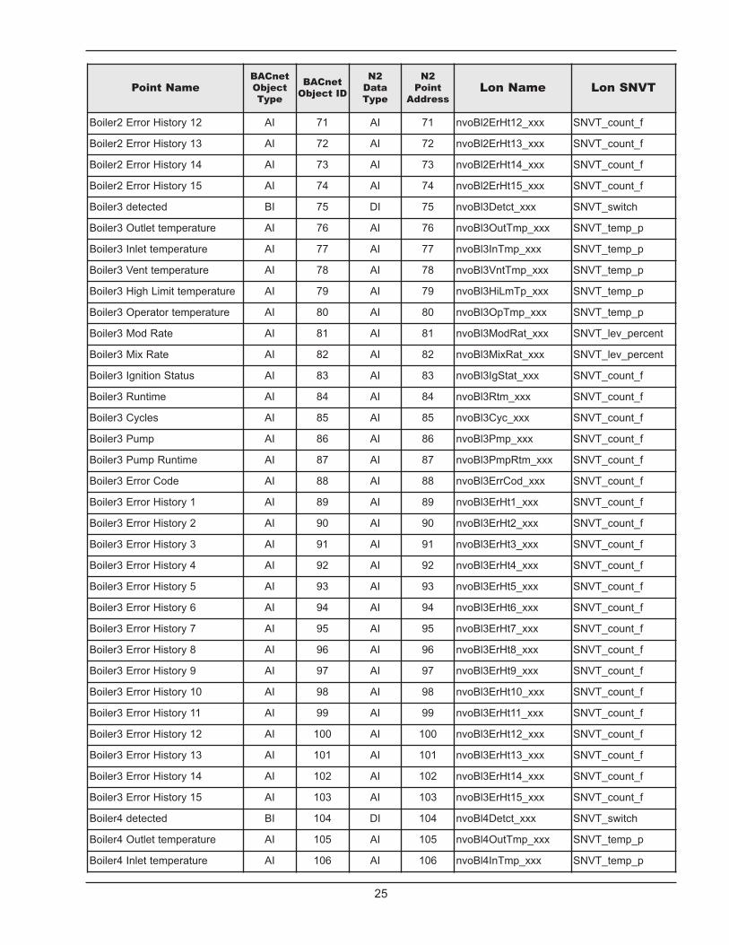
25
Point NameBACnetObjectType
BACnetObject ID
N2DataType
N2PointAddress
Lon Name Lon SNVT
Boiler2 Error History 12 AI 71 AI 71 nvoBl2ErHt12_xxx SNVT_count_f
Boiler2 Error History 13 AI 72 AI 72 nvoBl2ErHt13_xxx SNVT_count_f
Boiler2 Error History 14 AI 73 AI 73 nvoBl2ErHt14_xxx SNVT_count_f
Boiler2 Error History 15 AI 74 AI 74 nvoBl2ErHt15_xxx SNVT_count_f
Boiler3 detected BI 75 DI 75 nvoBl3Detct_xxx SNVT_switch
Boiler3 Outlet temperature AI 76 AI 76 nvoBl3OutTmp_xxx SNVT_temp_p
Boiler3 Inlet temperature AI 77 AI 77 nvoBl3InTmp_xxx SNVT_temp_p
Boiler3 Vent temperature AI 78 AI 78 nvoBl3VntTmp_xxx SNVT_temp_p
Boiler3 High Limit temperature AI 79 AI 79 nvoBl3HiLmTp_xxx SNVT_temp_p
Boiler3 Operator temperature AI 80 AI 80 nvoBl3OpTmp_xxx SNVT_temp_p
Boiler3 Mod Rate AI 81 AI 81 nvoBl3ModRat_xxx SNVT_lev_percent
Boiler3 Mix Rate AI 82 AI 82 nvoBl3MixRat_xxx SNVT_lev_percent
Boiler3 Ignition Status AI 83 AI 83 nvoBl3IgStat_xxx SNVT_count_f
Boiler3 Runtime AI 84 AI 84 nvoBl3Rtm_xxx SNVT_count_f
Boiler3 Cycles AI 85 AI 85 nvoBl3Cyc_xxx SNVT_count_f
Boiler3 Pump AI 86 AI 86 nvoBl3Pmp_xxx SNVT_count_f
Boiler3 Pump Runtime AI 87 AI 87 nvoBl3PmpRtm_xxx SNVT_count_f
Boiler3 Error Code AI 88 AI 88 nvoBl3ErrCod_xxx SNVT_count_f
Boiler3 Error History 1 AI 89 AI 89 nvoBl3ErHt1_xxx SNVT_count_f
Boiler3 Error History 2 AI 90 AI 90 nvoBl3ErHt2_xxx SNVT_count_f
Boiler3 Error History 3 AI 91 AI 91 nvoBl3ErHt3_xxx SNVT_count_f
Boiler3 Error History 4 AI 92 AI 92 nvoBl3ErHt4_xxx SNVT_count_f
Boiler3 Error History 5 AI 93 AI 93 nvoBl3ErHt5_xxx SNVT_count_f
Boiler3 Error History 6 AI 94 AI 94 nvoBl3ErHt6_xxx SNVT_count_f
Boiler3 Error History 7 AI 95 AI 95 nvoBl3ErHt7_xxx SNVT_count_f
Boiler3 Error History 8 AI 96 AI 96 nvoBl3ErHt8_xxx SNVT_count_f
Boiler3 Error History 9 AI 97 AI 97 nvoBl3ErHt9_xxx SNVT_count_f
Boiler3 Error History 10 AI 98 AI 98 nvoBl3ErHt10_xxx SNVT_count_f
Boiler3 Error History 11 AI 99 AI 99 nvoBl3ErHt11_xxx SNVT_count_f
Boiler3 Error History 12 AI 100 AI 100 nvoBl3ErHt12_xxx SNVT_count_f
Boiler3 Error History 13 AI 101 AI 101 nvoBl3ErHt13_xxx SNVT_count_f
Boiler3 Error History 14 AI 102 AI 102 nvoBl3ErHt14_xxx SNVT_count_f
Boiler3 Error History 15 AI 103 AI 103 nvoBl3ErHt15_xxx SNVT_count_f
Boiler4 detected BI 104 DI 104 nvoBl4Detct_xxx SNVT_switch
Boiler4 Outlet temperature AI 105 AI 105 nvoBl4OutTmp_xxx SNVT_temp_p
Boiler4 Inlet temperature AI 106 AI 106 nvoBl4InTmp_xxx SNVT_temp_p

26
Point NameBACnetObjectType
BACnetObject ID
N2DataType
N2PointAddress
Lon Name Lon SNVT
Boiler4 Vent temperature AI 107 AI 107 nvoBl4VntTmp_xxx SNVT_temp_p
Boiler4 High Limit temperature AI 108 AI 108 nvoBl4HiLmTp_xxx SNVT_temp_p
Boiler4 Operator temperature AI 109 AI 109 nvoBl4OpTmp_xxx SNVT_temp_p
Boiler4 Mod Rate AI 110 AI 110 nvoBl4ModRat_xxx SNVT_lev_percent
Boiler4 Mix Rate AI 111 AI 111 nvoBl4MixRat_xxx SNVT_lev_percent
Boiler4 Ignition Status AI 112 AI 112 nvoBl4IgStat_xxx SNVT_count_f
Boiler4 Runtime AI 113 AI 113 nvoBl4Rtm_xxx SNVT_count_f
Boiler4 Cycles AI 114 AI 114 nvoBl4Cyc_xxx SNVT_count_f
Boiler4 Pump AI 115 AI 115 nvoBl4Pmp_xxx SNVT_count_f
Boiler4 Pump Runtime AI 116 AI 116 nvoBl4PmpRtm_xxx SNVT_count_f
Boiler4 Error Code AI 117 AI 117 nvoBl4ErrCod_xxx SNVT_count_f
Boiler4 Error History 1 AI 118 AI 118 nvoBl4ErHt1_xxx SNVT_count_f
Boiler4 Error History 2 AI 119 AI 119 nvoBl4ErHt2_xxx SNVT_count_f
Boiler4 Error History 3 AI 120 AI 120 nvoBl4ErHt3_xxx SNVT_count_f
Boiler4 Error History 4 AI 121 AI 121 nvoBl4ErHt4_xxx SNVT_count_f
Boiler4 Error History 5 AI 122 AI 122 nvoBl4ErHt5_xxx SNVT_count_f
Boiler4 Error History 6 AI 123 AI 123 nvoBl4ErHt6_xxx SNVT_count_f
Boiler4 Error History 7 AI 124 AI 124 nvoBl4ErHt7_xxx SNVT_count_f
Boiler4 Error History 8 AI 125 AI 125 nvoBl4ErHt8_xxx SNVT_count_f
Boiler4 Error History 9 AI 126 AI 126 nvoBl4ErHt9_xxx SNVT_count_f
Boiler4 Error History 10 AI 127 AI 127 nvoBl4ErHt10_xxx SNVT_count_f
Boiler4 Error History 11 AI 128 AI 128 nvoBl4ErHt11_xxx SNVT_count_f
Boiler4 Error History 12 AI 129 AI 129 nvoBl4ErHt12_xxx SNVT_count_f
Boiler4 Error History 13 AI 130 AI 130 nvoBl4ErHt13_xxx SNVT_count_f
Boiler4 Error History 14 AI 131 AI 131 nvoBl4ErHt14_xxx SNVT_count_f
Boiler4 Error History 15 AI 132 AI 132 nvoBl4ErHt15_xxx SNVT_count_f
Auto Diff BI 133 DI 133 nvoAutoDiff_xxx SNVT_switch
Target Mode BV 134 DO 134 nviTargetMod_xxx SNVT_switch
Setpoint Target AV 135 AO 135 nviSPTarget_xxx SNVT_temp_p
Outdoor Start AV 136 AO 136 nviOutdrStrt_xxx SNVT_temp_p
Outdoor Design AV 137 AO 137 nviOutdrDsgn_xxx SNVT_temp_p
Boil Start AV 138 AO 138 nviBoilStrt_xxx SNVT_temp_p
Boil Design AV 139 AO 139 nviBoilDsgn_xxx SNVT_temp_p
Manual Differential AV 140 AO 140 nviManDiff_xxx SNVT_temp_p
DHW Exchange AV 141 AO 141 nviDHWExch_xxx SNVT_temp_p
DHW Tank AV 142 AO 142 nviDHWTank_xxx SNVT_temp_p

27
Point NameBACnetObjectType
BACnetObject ID
N2DataType
N2PointAddress
Lon Name Lon SNVT
DHW Differential AV 143 AO 143 nviDHWDiff_xxx SNVT_temp_p
DHW Priority BV 144 DO 144 nviDHWPrio_xxx SNVT_switch
DHW During UnOcc BV 145 DO 145 nviDHWUnOc_xxx SNVT_switch
WWSD During Occ AV 146 AO 146 nviWWSDOcc_xxx SNVT_temp_p
WWSD During UnOcc AV 147 AO 147 nviWWSDUnOc_xxx SNVT_temp_p
Tank Setpoint AV 148 AO 148 nviTnkSP_xxx SNVT_temp_p
Tank Differential AV 149 AO 149 nviTnkDiff_xxx SNVT_temp_p
Tank During UnOcc BV 150 DO 150 nviTkDurUnOc_xxx SNVT_switch
Pool Setpoint AV 151 AO 151 nviPoolSP_xxx SNVT_temp_p
Pool Differential AV 152 AO 152 nviPoolDiff_xxx SNVT_temp_p
Pool Supply Max AV 153 AO 153 nviPoolSupMx_xxx SNVT_temp_p
Pool During UnOcc BV 154 DO 154 nviPoolUnOcc_xxx SNVT_switch
System Pump AV 155 AO 155 nviSysPmp_xxx SNVT_count_f
DHW Pump AV 156 AO 156 nviDHWPmp_xxx SNVT_count_f
Boiler Pump AV 157 AO 157 nviBlrPmp_xxx SNVT_count_f
Target temperature AV 158 AO 158 nviTargetTmp_xxx SNVT_temp_p
Manual Differential AV 159 AO 159 nviManDiff_xxx SNVT_temp_p
Target Mod Rate AV 160 AO 160 nviTrgModRat_xxx SNVT_lev_percent
Target Mix Rate AV 161 AO 161 nviTrgMixRat_xxx SNVT_lev_percent
Boiler1 On/Off BV 162 DO 162 nviBlr1OnOff_xxx SNVT_switch
Boiler2 On/Off BV 163 DO 163 nviBlr2OnOff_xxx SNVT_switch
Boiler3 On/Off BV 164 DO 164 nviBlr3OnOff_xxx SNVT_switch
Boiler4 On/Off BV 165 DO 165 nviBlr4OnOff_xxx SNVT_switch

28
A7 A6 A5 A4 A3 A2 A1 A0 Address
Off Off Off Off Off Off Off Off 0Off Off Off Off Off Off Off On 1Off Off Off Off Off Off On Off 2Off Off Off Off Off Off On On 3Off Off Off Off Off On Off Off 4Off Off Off Off Off On Off On 5Off Off Off Off Off On On Off 6Off Off Off Off Off On On On 7Off Off Off Off On Off Off Off 8Off Off Off Off On Off Off On 9Off Off Off Off On Off On Off 10Off Off Off Off On Off On On 11Off Off Off Off On On Off Off 12Off Off Off Off On On Off On 13Off Off Off Off On On On Off 14Off Off Off Off On On On On 15Off Off Off On Off Off Off Off 16Off Off Off On Off Off Off On 17Off Off Off On Off Off On Off 18Off Off Off On Off Off On On 19Off Off Off On Off On Off Off 20Off Off Off On Off On Off On 21Off Off Off On Off On On Off 22Off Off Off On Off On On On 23Off Off Off On On Off Off Off 24Off Off Off On On Off Off On 25Off Off Off On On Off On Off 26Off Off Off On On Off On On 27Off Off Off On On On Off Off 28Off Off Off On On On Off On 29Off Off Off On On On On Off 30Off Off Off On On On On On 31Off Off On Off Off Off Off Off 32Off Off On Off Off Off Off On 33Off Off On Off Off Off On Off 34Off Off On Off Off Off On On 35Off Off On Off Off On Off Off 36Off Off On Off Off On Off On 37Off Off On Off Off On On Off 38
A7 A6 A5 A4 A3 A2 A1 A0 Address
Off Off On Off Off On On On 39Off Off On Off On Off Off Off 40Off Off On Off On Off Off On 41Off Off On Off On Off On Off 42Off Off On Off On Off On On 43Off Off On Off On On Off Off 44Off Off On Off On On Off On 45Off Off On Off On On On Off 46Off Off On Off On On On On 47Off Off On On Off Off Off Off 48Off Off On On Off Off Off On 49Off Off On On Off Off On Off 50Off Off On On Off Off On On 51Off Off On On Off On Off Off 52Off Off On On Off On Off On 53Off Off On On Off On On Off 54Off Off On On Off On On On 55Off Off On On On Off Off Off 56Off Off On On On Off Off On 57Off Off On On On Off On Off 58Off Off On On On Off On On 59Off Off On On On On Off Off 60Off Off On On On On Off On 61Off Off On On On On On Off 62Off Off On On On On On On 63Off On Off Off Off Off Off Off 64Off On Off Off Off Off Off On 65Off On Off Off Off Off On Off 66Off On Off Off Off Off On On 67Off On Off Off Off On Off Off 68Off On Off Off Off On Off On 69Off On Off Off Off On On Off 70Off On Off Off Off On On On 71Off On Off Off On Off Off Off 72Off On Off Off On Off Off On 73Off On Off Off On Off On Off 74Off On Off Off On Off On On 75Off On Off Off On On Off Off 76Off On Off Off On On Off On 77Off On Off Off On On On Off 78Off On Off Off On On On On 79
Appendix B.2. Address DIP SwitchSettings

29
A7 A6 A5 A4 A3 A2 A1 A0 Address
Off On On On On Off Off Off 120Off On On On On Off Off On 121Off On On On On Off On Off 122Off On On On On Off On On 123Off On On On On On Off Off 124Off On On On On On Off On 125Off On On On On On On Off 126Off On On On On On On On 127On Off Off Off Off Off Off Off 128On Off Off Off Off Off Off On 129On Off Off Off Off Off On Off 130On Off Off Off Off Off On On 131On Off Off Off Off On Off Off 132On Off Off Off Off On Off On 133On Off Off Off Off On On Off 134On Off Off Off Off On On On 135On Off Off Off On Off Off Off 136On Off Off Off On Off Off On 137On Off Off Off On Off On Off 138On Off Off Off On Off On On 139On Off Off Off On On Off Off 140On Off Off Off On On Off On 141On Off Off Off On On On Off 142On Off Off Off On On On On 143On Off Off On Off Off Off Off 144On Off Off On Off Off Off On 145On Off Off On Off Off On Off 146On Off Off On Off Off On On 147On Off Off On Off On Off Off 148On Off Off On Off On Off On 149On Off Off On Off On On Off 150On Off Off On Off On On On 151On Off Off On On Off Off Off 152On Off Off On On Off Off On 153On Off Off On On Off On Off 154On Off Off On On Off On On 155On Off Off On On On Off Off 156On Off Off On On On Off On 157On Off Off On On On On Off 158On Off Off On On On On On 159On Off On Off Off Off Off Off 160
A7 A6 A5 A4 A3 A2 A1 A0 Address
Off On Off On Off Off Off Off 80Off On Off On Off Off Off On 81Off On Off On Off Off On Off 82Off On Off On Off Off On On 83Off On Off On Off On Off Off 84Off On Off On Off On Off On 85Off On Off On Off On On Off 86Off On Off On Off On On On 87Off On Off On On Off Off Off 88Off On Off On On Off Off On 89Off On Off On On Off On Off 90Off On Off On On Off On On 91Off On Off On On On Off Off 92Off On Off On On On Off On 93Off On Off On On On On Off 94Off On Off On On On On On 95Off On On Off Off Off Off Off 96Off On On Off Off Off Off On 97Off On On Off Off Off On Off 98Off On On Off Off Off On On 99Off On On Off Off On Off Off 100Off On On Off Off On Off On 101Off On On Off Off On On Off 102Off On On Off Off On On On 103Off On On Off On Off Off Off 104Off On On Off On Off Off On 105Off On On Off On Off On Off 106Off On On Off On Off On On 107Off On On Off On On Off Off 108Off On On Off On On Off On 109Off On On Off On On On Off 110Off On On Off On On On On 111Off On On On Off Off Off Off 112Off On On On Off Off Off On 113Off On On On Off Off On Off 114Off On On On Off Off On On 115Off On On On Off On Off Off 116Off On On On Off On Off On 117Off On On On Off On On Off 118Off On On On Off On On On 119Off On On On On Off Off Off 120

30
A7 A6 A5 A4 A3 A2 A1 A0 Address
On On Off Off On Off On Off 202On On Off Off On Off On On 203On On Off Off On On Off Off 204On On Off Off On On Off On 205On On Off Off On On On Off 206On On Off Off On On On On 207On On Off On Off Off Off Off 208On On Off On Off Off Off On 209On On Off On Off Off On Off 210On On Off On Off Off On On 211On On Off On Off On Off Off 212On On Off On Off On Off On 213On On Off On Off On On Off 214On On Off On Off On On On 215On On Off On On Off Off Off 216On On Off On On Off Off On 217On On Off On On Off On Off 218On On Off On On Off On On 219On On Off On On On Off Off 220On On Off On On On Off On 221On On Off On On On On Off 222On On Off On On On On On 223On On On Off Off Off Off Off 224On On On Off Off Off Off On 225On On On Off Off Off On Off 226On On On Off Off Off On On 227On On On Off Off On Off Off 228On On On Off Off On Off On 229On On On Off Off On On Off 230On On On Off Off On On On 231On On On Off On Off Off Off 232On On On Off On Off Off On 233On On On Off On Off On Off 234On On On Off On Off On On 235On On On Off On On Off Off 236On On On Off On On Off On 237On On On Off On On On Off 238On On On Off On On On On 239On On On On Off Off Off Off 240On On On On Off Off Off On 241On On On On Off Off On Off 242
A7 A6 A5 A4 A3 A2 A1 A0 Address
On Off On Off Off Off Off On 161On Off On Off Off Off On Off 162On Off On Off Off Off On On 163On Off On Off Off On Off Off 164On Off On Off Off On Off On 165On Off On Off Off On On Off 166On Off On Off Off On On On 167On Off On Off On Off Off Off 168On Off On Off On Off Off On 169On Off On Off On Off On Off 170On Off On Off On Off On On 171On Off On Off On On Off Off 172On Off On Off On On Off On 173On Off On Off On On On Off 174On Off On Off On On On On 175On Off On On Off Off Off Off 176On Off On On Off Off Off On 177On Off On On Off Off On Off 178On Off On On Off Off On On 179On Off On On Off On Off Off 180On Off On On Off On Off On 181On Off On On Off On On Off 182On Off On On Off On On On 183On Off On On On Off Off Off 184On Off On On On Off Off On 185On Off On On On Off On Off 186On Off On On On Off On On 187On Off On On On On Off Off 188On Off On On On On Off On 189On Off On On On On On Off 190On Off On On On On On On 191On On Off Off Off Off Off Off 192On On Off Off Off Off Off On 193On On Off Off Off Off On Off 194On On Off Off Off Off On On 195On On Off Off Off On Off Off 196On On Off Off Off On Off On 197On On Off Off Off On On Off 198On On Off Off Off On On On 199On On Off Off On Off Off Off 200On On Off Off On Off Off On 201

31
A7 A6 A5 A4 A3 A2 A1 A0 Address
On On On On Off Off On On 243On On On On Off On Off Off 244On On On On Off On Off On 245On On On On Off On On Off 246On On On On Off On On On 247On On On On On Off Off Off 248On On On On On Off Off On 249On On On On On Off On Off 250On On On On On Off On On 251On On On On On On Off Off 252On On On On On On Off On 253On On On On On On On Off 254On On On On On On On On 255

32
Appendix C. SpecificationsAppendix C.1. Specifications
Compliance with UL Regulations
For UL compliance, the following instructions must bemet when operating the ProtoNode.
• The units shall be powered by listed LPS or Class 2 power supply suited to the expected operating temperature range.
• The interconnecting power connector and power cable shall:• Comply with local electrical code.• Be suited to the expected operating tempera
ture range.• Meet the current and voltage rating for the
ProtoNode/Net
• Furthermore, the interconnecting power cable shall:• Be of length not exceeding 3.05m (118.3”)• Be constructed of materials rated VW-1 or
FT-1 or better
• If the unit is to be installed in an operating environment with a temperature above 65 °C, it should be installed in a Restricted Access Area requiring a key or a special tool to gain access
• This device must not be connected to a LAN segment with outdoor wiring.
ProtoNode RER ProtoNode LER
Electrical Connections
One 6-pin Phoenix connector, one RS-485 +/- ground port, power +/- frame ground port
One 3-pin RS-485 Phoenix connector, one RS-485 +/- ground port
One Ethernet-10/100 Ethernet port
One 6-pin Phoenix connector, one RS-485 +/- ground port, power +/- frame ground port
One Ethernet 10/100 BaseT portOne FTT-10 LonWorks port
ApprovalsPending CE (EN55022;EN55024; EN60950), UL916, Pending FCC Class A Part 15, DNP3
Conformance Tested, OPC Self-tested for Compliance, RoHS Compliant, CSA 205 Approved
BTL Marked LonMark Certified
PowerRequirements Multi-mode power adapter: 9-30VDC or 12 - 24VACC
PhysicalDimensions 11.5 cm L x 8.3 cm W x 4.1 cm H (4.5 x 3.2 x 1.6 in.)
Weight 0.2 kg (0.4 lbs)
OperatingTemperature -40°C to 75°C (-40°F to167°F)
SurgeSuppression EN61000-4-2 ESD EN61000-4-3 EMC EN61000-4-4 EFT
Humidity 5 - 90% RH (non-condensing)
(Specifications subject to change without notice)
33
Limited 2 year Warranty
FieldServer Technologies warrants its products to befree from defects in workmanship or material undernormal use and service for two years after date ofshipment. FieldServer Technologies will repair orreplace any equipment found to be defective duringthe warranty period. Final determination of thenature and responsibility for defective or damagedequipment will be made by FieldServer Technologiespersonnel.All warranties hereunder are contingent upon properuse in the application for which the product wasintended and do not cover products which have beenmodified or repaired without FieldServerTechnologies approval or which have been subjectedto accident, improper maintenance, installation orapplication, or on which original identification markshave been removed or altered. This LimitedWarranty also will not apply to interconnecting cablesor wires, consumables or to any damage resultingfrom battery leakage.In all cases FieldServer Technology’s responsibilityand liability under this warranty shall be limited to thecost of the equipment. The purchaser must obtainshipping instructions for the prepaid return of anyitem under this warranty provision and compliancewith such instruction shall be a condition of this war-ranty.Except for the express warranty stated above,FieldServer Technologies disclaims all warrantieswith regard to the products sold hereunder includingall implied warranties of merchantability and fitnessand the express warranties stated herein are in lieuof all obligations or liabilities on the part ofFieldServer Technologies for damages including, butnot limited to, consequential damages arising outof/or in connection with the use or performance of theproduct.

34
THIS PAGE INTENTIONALLY LEFT BLANK

35
THIS PAGE INTENTIONALLY LEFT BLANK

36
www.raypak.com Raypak, Inc., 2151 Eastman Avenue, Oxnard, CA 93030 (805) 278-5300 Fax (805) 278-9725
Litho in U.S.A.