Embed Size (px)
Citation preview
Prototype of Mobile Robot Vacuum Cleaner Based on Microcontroller
Jacquline Morlav S. Waworundeng 1*, Charlie Deeng2 and Gerald Richi Deeng3
1,2,3Computer Science Faculty, Universitas Manado, Indonesia; [email protected]
Abstract: Cleanness is important because it can affect the health of its inhabitants. Cleaning the
dust on the floor manually use broom or vacuum cleaner. Vacuum cleaner is tools that vacuuming
the dust with direct control of user. This research presents simple prototype of mobile robot
vacuum cleaner that can operate automatically by vacuuming the dust on flat floor surface.
Prototype is built with three ultrasonic sensors that can detect and avoid obstacles surround.
Prototyping Model is used as a basic method. Arduino IDE with C programming language are
used to create program code for microcontroller. Hardware build in microcontroller Arduino Uno
board, mini vacuum cleaner, ultrasonic sensor for sensing obstacles, voltage sensor, Lithium
Polymer (LiPo) battery as the power source, motor DC to spin wheels and perform robot
locomotion, LCD to display battery level, module timer to set operation time of robot, and Buzzer
alarm to notify when the battery power running low. The results of this research is a physical
prototype of mobile robot vacuum cleaner embed with simple locomotion algorithm, which detect
and avoid obstacle also to perform main function to absorb dust.
Keywords: mobile robot, vacuum cleaner, microcontroller, Arduino, ultrasonic sensor.
INTRODUCTION
The results of technology bring wide influence to the community to fulfill the needs of
everyday life. Computer technology especially in the field of hardware development show better
results to help human in doing works. Many researches in advanced robots field,
telecommunications, home security systems and computer systems use microcontrollers as the
main controller. Control system that can be made from microcontroller is an embedded system
that has a sense to make a robotic application that can perform tasks automatically.
Robot is a mechanical device that can perform physical tasks using human supervision and
control or using a program that has been defined. Robots are usually used for heavy-duty,
dangerous, repetitive and dirty jobs. Robot become more cost effective at their jobs and as the
human labor continues to become more expensive, more and more industrial jobs become
candidates for robotic automation (Craig, 2005). Most robots are used in industry, but along with
the development, the robot has begun to enter the field of entertainment and education, household
auxiliaries such as vacuum cleaners and lawn mowers.
Robot technology has reached out in terms of doing chore at home in example in
vacuuming the dust on the floor. Vacuum cleaner is a tools widely used to help human cleaning
the floor from the dust (Gantz, 2012). Technologies keep on improving to create vacuum cleaner
machine that become part of modern culture. For example Neato XV-11 comes with robotics
intelligence that assures the robot cleans the entire floor, carefully avoiding furniture, walls and
other objects (Neato, 2009).
This research is related with design and building prototype of mobile robot vacuum cleaner
based on microcontroller that can operate automatically. Prototype of mobile vacuum cleaner are
able perform locomotion, detect and avoid collision with the main function to vacuum dust on the
surface of flat floor. Hardware and software are used to build the prototype of mobile robot
vacuum cleaner. Main hardware components such as microcontroller Arduino Uno, ultrasonic
sensor, module timer, Liquid Crystal Display (LCD), buzzer, DC voltage sensor, motor DC are
being used and shortly explained.
1. Microcontroller
Microcontroller is essentially an inexpensive single-chip computer contains a Central
Processing Unit (CPU), Random Access Memory (RAM), Read Only Memory (ROM),
Input/Output (I/O) lines, serial and parallel ports, timers, and Analog to Digital (A/D) and
Digital-to-Analog (D/A) converters. The key feature however is the microcontroller’s
capability of uploading, storing, and running a program (Iovine, 2004). The prototype of
mobile robot vacuum cleaner build with microcontroller board Arduino Uno based on
ATmega328. Arduino is a tiny computer process inputs and outputs between the device and
external components connected to it (McRoberts, 2010). Arduino board can be programmed
using Arduino Integrated Development Environment (Arduino IDE). Arduino Uno is used to
process the input from sensors, which will produce an output to control the other
components.
2. Ultrasonic Sensor
Ultrasonic sensor used to sense the obstacles surround robot environment. The prototype of
robot is using Parallax Ping ultrasonic sensor. The Parallax Ping ultrasonic distance sensor
provides precise, non-contact distance measurements from about 2 cm (0.8 inches) to 3
meters (3.3 yards). It is very easy to connect to microcontrollers such as the BASIC Stamp
Propeller chip, or Arduino, requiring only one I/O pin (Parallax Inc, 2013).
3. Liquid Crystal Display (LCD)
LCD is a component that can be connected to microcontroller. LCD can be use to display
data text to the user or developer while designing or debugging (Cypress, 2015). In the
building of robot prototype, LCD is use to display the battery level status.
4. Actuators
Actuators are part as a driver of the instruction program. Actuators are usually
electromechanical devices that generate a propulsive force. Actuators are used in this
research is motor of direct current (motor DC) is a machine that functions convert the direct
current electric power into motion or mechanical energy, which in the form of kinetic energy
of rotation of the motor. Generally, control function of motor includes open loop, forward,
reverse direction and run enable (On Semiconductor, 2013).
5. Module Timer
Module Timer is use to set the operation time of the robot. Operation time of robot defines
how long the robot will active and perform task.
METHODS, DESIGN AND FUNCTIONAL ANALYSIS
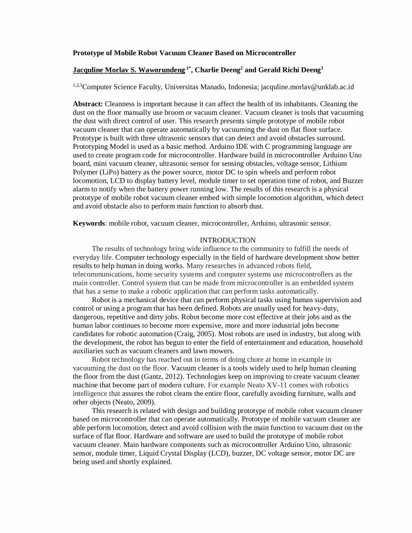
Research method is based on prototyping paradigm (Pressman, 2015), with five stages
namely communication, quick plan, modeling quick design, construction of prototype, and
deployment delivery and feedback. The prototyping paradigm begins with communication, where
developers identify terms and requirements. Iteration prototyping is planned quickly and then
modeled. Quick design, focus on representation of software aspects that will be seen by end user.
Quick design leads to construction of prototype. Prototype then evaluated and provides feedback
for development. Iterations occur in the prototype to meet the needs of stakeholders, and to gain
an understanding of what needs to be done. The process model of Prototyping is shown in
Figure 1. Data collection in this research is based on literature study, by reviewing related
documents from books, journal and official documents. In case of building the program, C
programming language had been used with Arduino IDE. The hardware development
environment consists of main components.
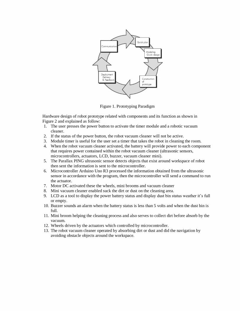
Figure 1. Prototyping Paradigm
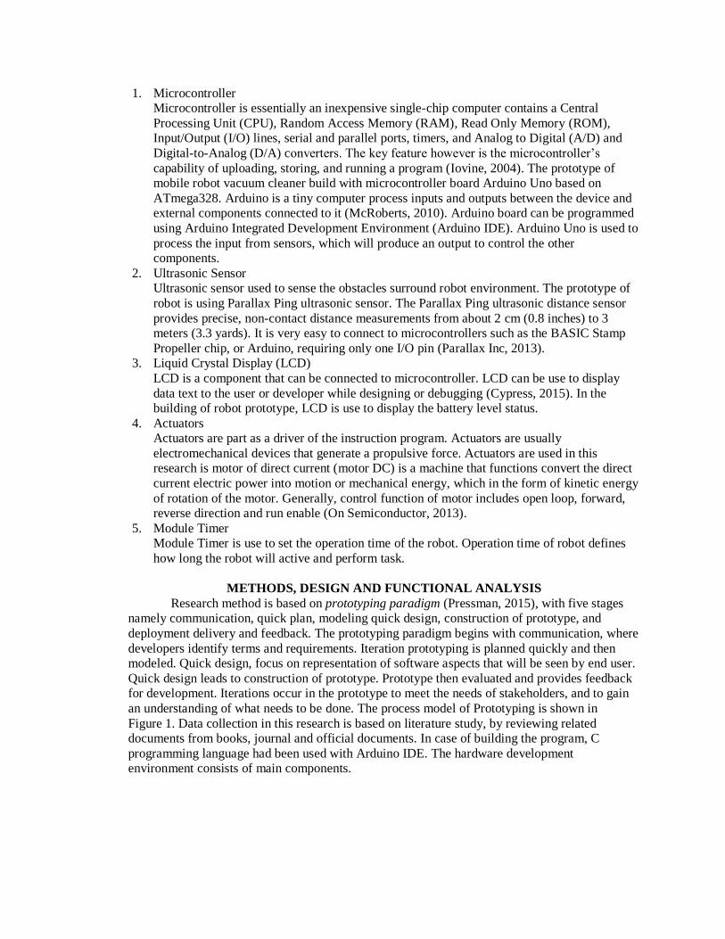
Hardware design of robot prototype related with components and its function as shown in
Figure 2 and explained as follow:
1. The user presses the power button to activate the timer module and a robotic vacuum
cleaner.
2. If the status of the power button, the robot vacuum cleaner will not be active.
3. Module timer is useful for the user set a timer that takes the robot in cleaning the room.
4. When the robot vacuum cleaner activated, the battery will provide power to each component
that requires power contained within the robot vacuum cleaner (ultrasonic sensors,
microcontrollers, actuators, LCD, buzzer, vacuum cleaner mini).
5. The Parallax PING ultrasonic sensor detects objects that exist around workspace of robot
then sent the information is sent to the microcontroller.
6. Microcontroller Arduino Uno R3 processed the information obtained from the ultrasonic
sensor in accordance with the program, then the microcontroller will send a command to run
the actuator.
7. Motor DC activated these the wheels, mini brooms and vacuum cleaner
8. Mini vacuum cleaner enabled suck the dirt or dust on the cleaning area.
9. LCD as a tool to display the power battery status and display dust bin status weather it’s full
or empty.
10. Buzzer sounds an alarm when the battery status is less than 5 volts and when the dust bin is
full.
11. Mini broom helping the cleaning process and also serves to collect dirt before absorb by the
vacuum.
12. Wheels driven by the actuators which controlled by microcontroller.
13. The robot vacuum cleaner operated by absorbing dirt or dust and did the navigation by
avoiding obstacle objects around the workspace.
Figure 2. Hardware Components of Mobile Robot Vacuum Cleaner
Prototype of mobile robot vacuum cleaner has some features as described below:
1. Equip with 3 ultrasonic sensors with a detection distance of at least 1 inch (2cm - 3m)
that can detect objects around it, and allowing the robot to detect if there are obstacles
and avoid crash.
2. Robot has a timer module related with operation time needed by the robot to do the
cleaning task. User can set the operation time within range 1 and up to 15 minutes
maximum.
3. The robot is equipped with mini broom cleaning tool that help to maximize the cleaning
process in the area that is passed.
4. Robot has a buzzer that sounding an alarm when the battery is almost empty and the dust
bin is full.
5. The battery level is also displayed on the LCD screen.
6. When the robot hit an object, then robot will calculate and detect the object and try to
avoid the obstacles and keep moving.
7. Robot will stop by three conditions. The first is when the time set by the user is reached.
Second when the user turn off the robot. Third when the power is empty.
Analysis and design deals with the question of how to build autonomous mobile robot
system using sensors, microcontroller, actuator and other additional electronic components which
can functioning as a mobile robot vacuum cleaner to absorb dust and has the ability to detect and
avoid obstacles. The answer explained with Unified Modeling Language (UML) using use case
diagram. Use case diagram is a diagram illustrates the functionality expected in system. Use case
diagram present interaction within processes and the actors with the system. Use case diagram of
mobile robot vacuum cleaner are shown in Figure 3. There are seven use cases. First use case On,
show the function to activated the robot. The actor is robot itself, precondition is off and post condition is On. Use case Supply Power related with the power distribution to other components
in the system. Use case Supply Power share the battery power to ultrasonic sensor,
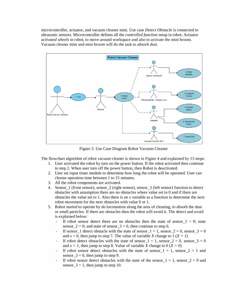
microcontroller, actuator, and vacuum cleaner mini. Use case Detect Obstacle is connected to
ultrasonic sensors. Microcontroller defines all the controlled function setup in robot. Actuator
activated wheels in robot, to move around workspace and also to activate the mini broom.
Vacuum cleaner mini and mini broom will do the task to absorb dust.
Figure 3. Use Case Diagram Robot Vacuum Cleaner
The flowchart algorithm of robot vacuum cleaner is shown in Figure 4 and explained by 13 steps:
1. User activated the robot by turn on the power button. If the robot activated then continue
to step 2. When user turn off the power button, then Robot is deactivated.
2. User set input timer module to determine how long the robot will be operated. User can
choose operation time between 1 to 15 minutes.
3. All the robot components are activated.
4. Sensor_1 (front sensor), sensor_2 (right sensor), sensor_3 (left sensor) function to detect
obstacles with assumption there are no obstacles where value set to 0 and if there are
obstacles the value set to 1. Also there is an x variable as a function to determine the next
robot movement for the next obstacles with value 0 or 1.
5. Robot started to operate by do locomotion along the area of cleaning, to absorb the dust
or small particles. If there are obstacles then the robot will avoid it. The detect and avoid
is explained below:
- If robot sensor detect there are no obstacles then the state of sensor_1 = 0; state
sensor_2 = 0; and state of sensor_3 = 0, then continue to step 6.
- If sensor_1 detect obstacle with the state of sensor_1 = 1, sensor_2 = 0, sensor_3 = 0
and x = 0, then jump to step 7. The value of variable X change to 1 (X = 1)
- If robot detect obstacles with the state of sensor_1 = 1, sensor_2 = 0, sensor_3 = 0
and x = 1, then jump to step 8. Value of variable X change to 0 (X = 0)
- If robot sensor detect obstacles with the state of sensor_1 = 1, sensor_2 = 1 and
sensor_3 = 0, then jump to step 9.
- If robot sensor detect obstacles with the state of the sensor_1 = 1, sensor_2 = 0 and
sensor_3 = 1, then jump to step 10.
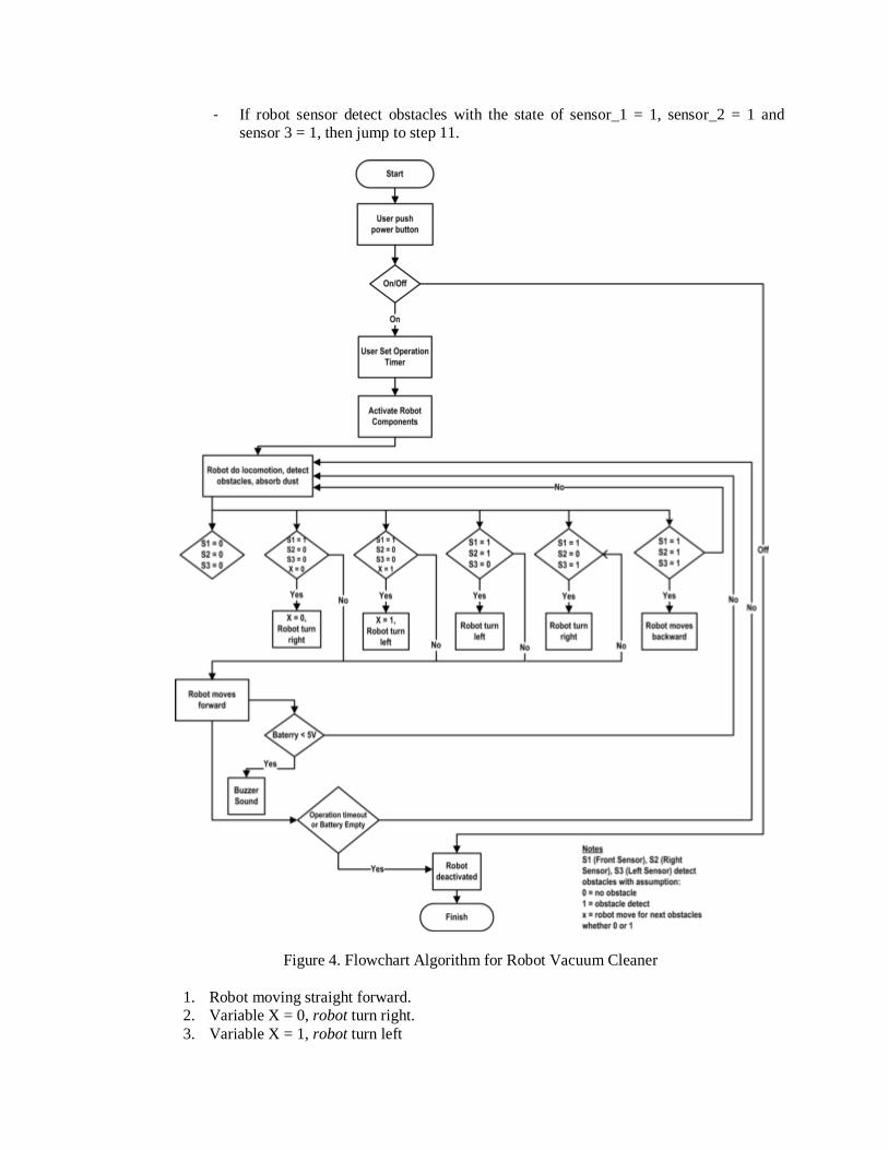
- If robot sensor detect obstacles with the state of sensor_1 = 1, sensor_2 = 1 and
sensor 3 = 1, then jump to step 11.
Figure 4. Flowchart Algorithm for Robot Vacuum Cleaner
1. Robot moving straight forward.
2. Variable X = 0, robot turn right.
3. Variable X = 1, robot turn left
4. Robot turn left.
5. Robot turn right.
6. Robot moving backwards and revert to step 5.
7. When robot activated and the battery less then 5 volt, then continue robot sound an alarm
from buzzer.
8. Robot will repeat the condition in step 5 while doing the cleaning until the time set by the
user in step 2 ended or user turn off the robot in step 1.
IMPLEMENTATION OF MOBILE ROBOT VACUUM CLEANER
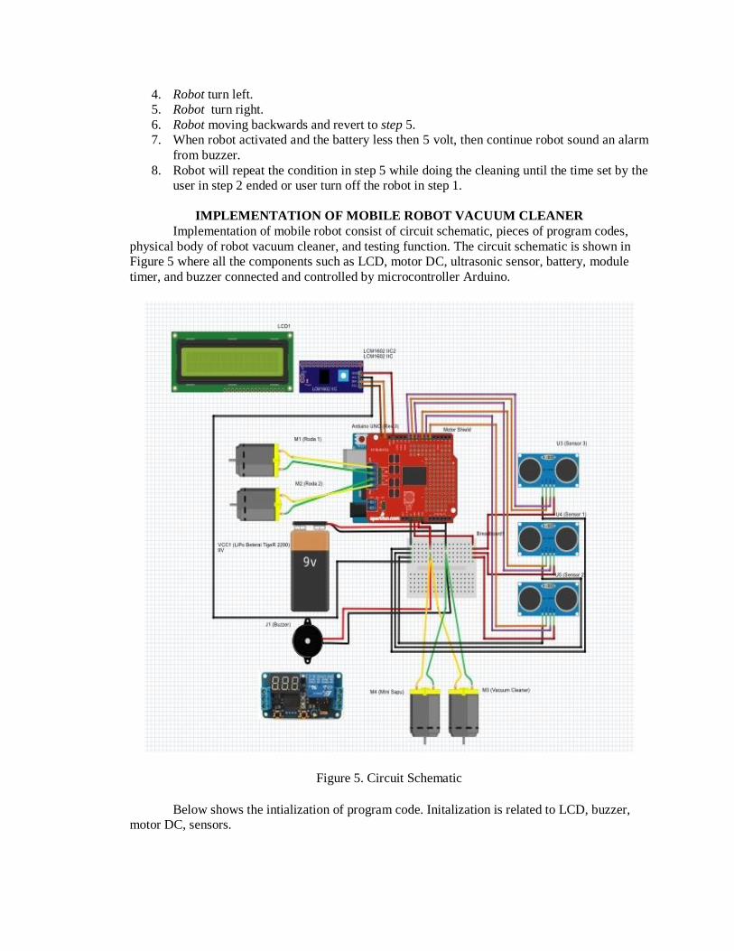
Implementation of mobile robot consist of circuit schematic, pieces of program codes,
physical body of robot vacuum cleaner, and testing function. The circuit schematic is shown in
Figure 5 where all the components such as LCD, motor DC, ultrasonic sensor, battery, module
timer, and buzzer connected and controlled by microcontroller Arduino.
Figure 5. Circuit Schematic
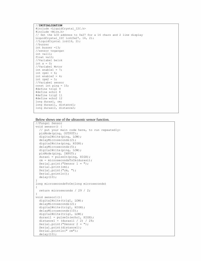
Below shows the intialization of program code. Initalization is related to LCD, buzzer,
motor DC, sensors.
//INITIALIZATION
#include <LiquidCrystal_I2C.h>
#include <Wire.h>
// Set the LCD address to 0x27 for a 16 chars and 2 line display
LiquidCrystal_I2C lcd(0x27, 16, 2);
//LiquidCrystal lcd(16, 2);
//buzzer
int buzzer =13;
//sensor tegangan
int val11;
float val2;
//Variabel belok
int x = 0;
//Variabel Motor
int enable1 = 7;
int rpm1 = 6;
int enable2 = 4;
int rpm2 = 5;
//Variabel sensor
const int ping = 10;
#define trig1 9
#define echo1 8
#define trig2 11
#define echo2 12
long durasi, cm;
long durasi1, distance1;
long durasi2, distance2;
Below shows one of the ultrasonic sensor function. //Fungsi Sensor
void sensor() {
// put your main code here, to run repeatedly:
pinMode(ping, OUTPUT);
digitalWrite(ping, LOW);
delayMicroseconds(2);
digitalWrite(ping, HIGH);
delayMicroseconds(5);
digitalWrite(ping, LOW);
pinMode(ping, INPUT);
durasi = pulseIn(ping, HIGH);
cm = microsecondsToCm(durasi);
Serial.print("Sensor 1 = ");
Serial.print(cm);
Serial.print("cm, ");
Serial.println();
delay(10);
}
long microsecondsToCm(long microseconds)
{
return microseconds / 29 / 2;
}
void sensor1(){
digitalWrite(trig1, LOW);
delayMicroseconds(2);
digitalWrite(trig1, HIGH);
delayMicroseconds(10);
digitalWrite(trig1, LOW);
durasi1 = pulseIn(echo1, HIGH);
distance1 = (durasi1 / 2) / 29;
Serial.print("Sensor 2 = ");
Serial.print(distance1);
Serial.println(" cm");
delay(10);
Below show the pieces of program code to control the motor DC in functional robot movement // Fungsi Motor Gerak
void maju1()
{
digitalWrite(enable1, HIGH);
analogWrite(rpm1, 130);
}
void maju2()
{
digitalWrite(enable2, HIGH);
analogWrite(rpm2, 130);
}
void mundur1()
{
digitalWrite(enable1, LOW);
analogWrite(rpm1, 130);
}
void mundur2()
{
digitalWrite(enable2, LOW);
analogWrite(rpm2, 130);
}
void berhenti1()
{
analogWrite(rpm1,0);
}
void berhenti2()
{
analogWrite(rpm2,0);
}
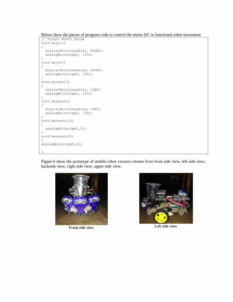
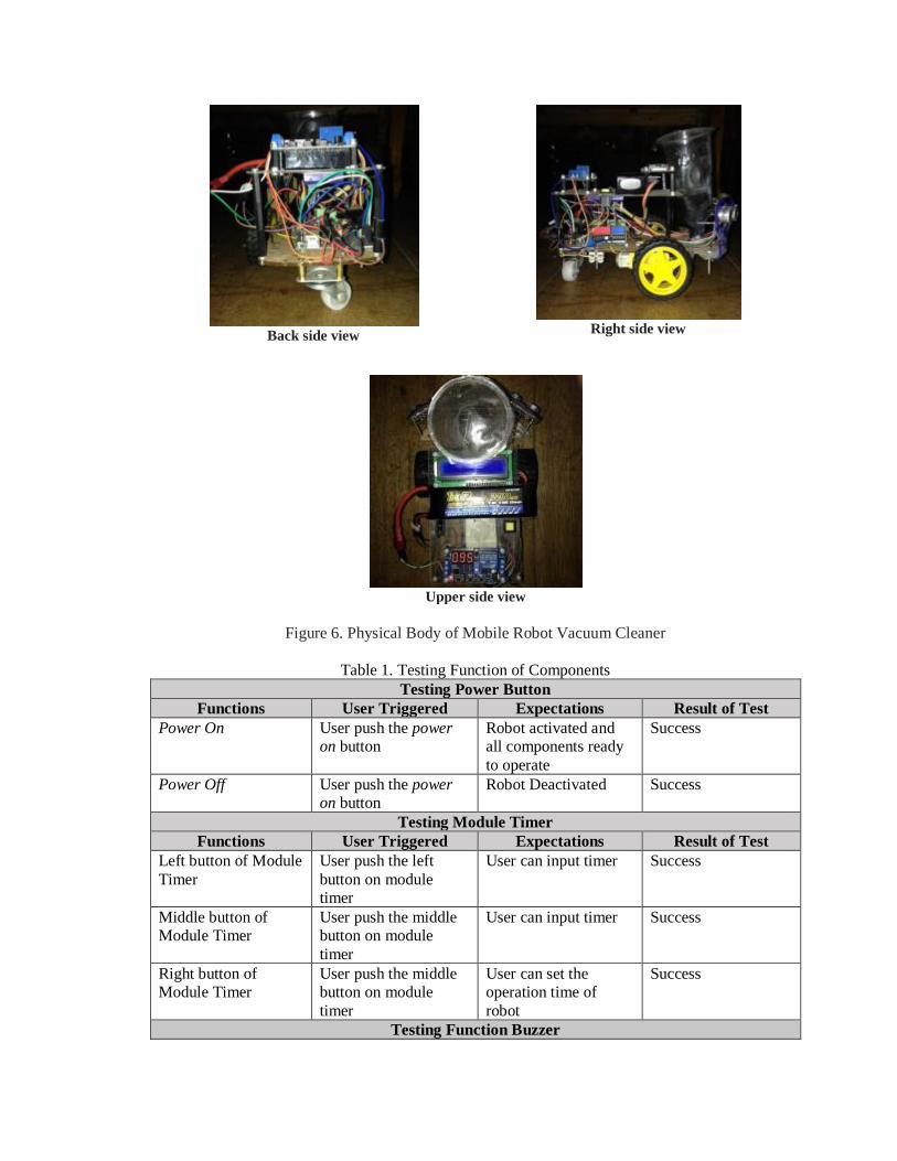
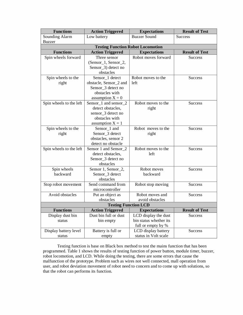
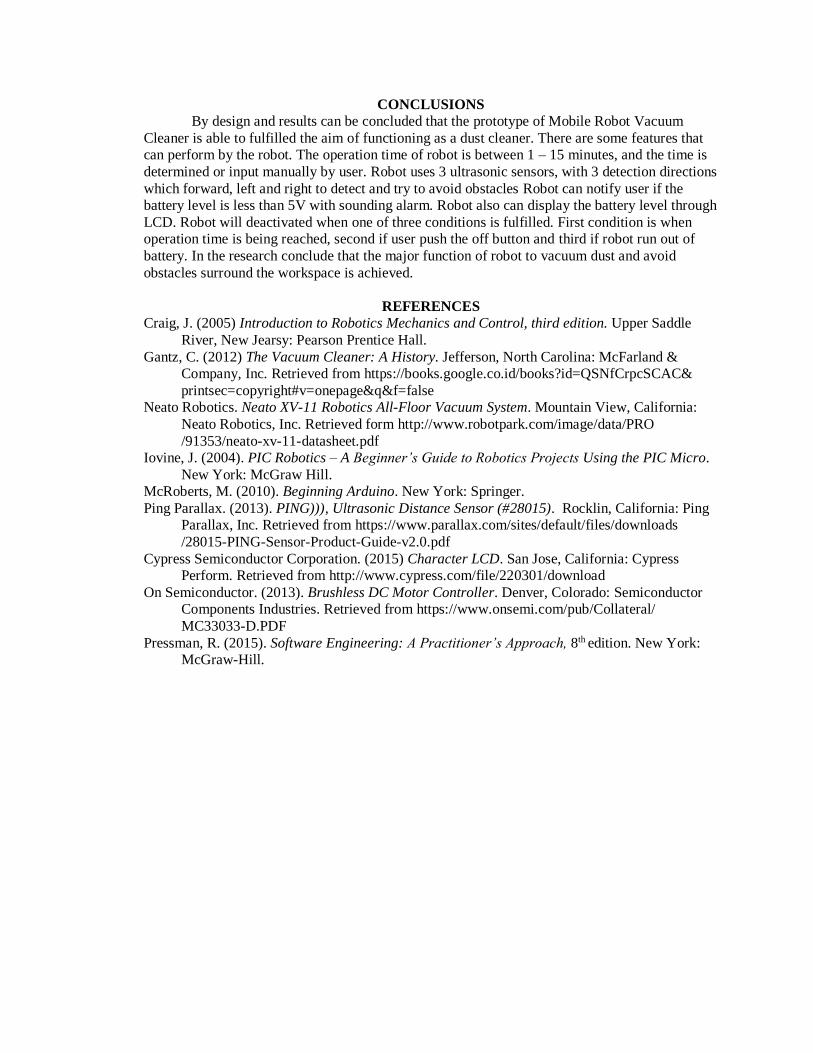
Figure 6 show the prototype of mobile robot vacuum cleaner from front side view, left side view,
backside view, right side view, upper side view.
Front side view
Left side view
Back side view
Right side view
Upper side view
Figure 6. Physical Body of Mobile Robot Vacuum Cleaner
Table 1. Testing Function of Components
Testing Power Button
Functions User Triggered Expectations Result of Test
Power On User push the power
on button
Robot activated and
all components ready
to operate
Success
Power Off User push the power
on button
Robot Deactivated Success
Testing Module Timer
Functions User Triggered Expectations Result of Test
Left button of Module
Timer
User push the left
button on module
timer
User can input timer Success
Middle button of
Module Timer
User push the middle
button on module
timer
User can input timer Success
Right button of
Module Timer
User push the middle
button on module
timer
User can set the
operation time of
robot
Success
Testing Function Buzzer
Functions Action Triggered Expectations Result of Test
Sounding Alarm
Buzzer
Low battery Buzzer Sound Success
Testing Function Robot Locomotion
Functions Action Triggered Expectations Result of Test
Spin wheels forward Three sensor
(Sensor_1, Sensor_2,
Sensor_3) detect no
obstacles
Robot moves forward Success
Spin wheels to the
right
Sensor_1 detect
obstacle, Sensor_2 and
Sensor_3 detect no
obstacles with
assumption X = 0
Robot moves to the
left
Success
Spin wheels to the left Sensor_1 and sensor_2
detect obstacles,
sensor_3 detect no
obstacles with
assumption X = 1
Robot moves to the
right
Success
Spin wheels to the
right
Sensor_1 and
Sensor_3 detect
obstacles, sensor 2
detect no obstacle
Robot moves to the
right
Success
Spin wheels to the left Sensor 1 and Sensor_2
detect obstacles,
Sensor_3 detect no
obstacles
Robot moves to the
left
Success
Spin wheels
backward
Sensor 1, Sensor_2,
Sensor_3 detect
obstacles
Robot moves
backward
Success
Stop robot movement Send command from
microcontroller
Robot stop moving Success
Avoid obstacles Put an object as
obstacles
Robot moves and
avoid obstacles
Success
Testing Function LCD
Functions Action Triggered Expectations Result of Test
Display dust bin
status
Dust bin full or dust
bin empty
LCD display the dust
bin status whether its
full or empty by %
Success
Display battery level
status
Battery is full or
empty
LCD display battery
status in Volt scale
Success
Testing function is base on Black box method to test the mains function that has been
programmed. Table 1 shows the results of testing function of power button, module timer, buzzer,
robot locomotion, and LCD. While doing the testing, there are some errors that cause the
malfunction of the prototype. Problem such as wires not well connected, mall operation from
user, and robot deviation movement of robot need to concern and to come up with solutions, so
that the robot can performs its function.
CONCLUSIONS
By design and results can be concluded that the prototype of Mobile Robot Vacuum
Cleaner is able to fulfilled the aim of functioning as a dust cleaner. There are some features that
can perform by the robot. The operation time of robot is between 1 – 15 minutes, and the time is
determined or input manually by user. Robot uses 3 ultrasonic sensors, with 3 detection directions
which forward, left and right to detect and try to avoid obstacles Robot can notify user if the
battery level is less than 5V with sounding alarm. Robot also can display the battery level through
LCD. Robot will deactivated when one of three conditions is fulfilled. First condition is when
operation time is being reached, second if user push the off button and third if robot run out of
battery. In the research conclude that the major function of robot to vacuum dust and avoid
obstacles surround the workspace is achieved.
REFERENCES
Craig, J. (2005) Introduction to Robotics Mechanics and Control, third edition. Upper Saddle
River, New Jearsy: Pearson Prentice Hall.
Gantz, C. (2012) The Vacuum Cleaner: A History. Jefferson, North Carolina: McFarland &
Company, Inc. Retrieved from https://books.google.co.id/books?id=QSNfCrpcSCAC&
printsec=copyright#v=onepage&q&f=false
Neato Robotics. Neato XV-11 Robotics All-Floor Vacuum System. Mountain View, California:
Neato Robotics, Inc. Retrieved form http://www.robotpark.com/image/data/PRO
/91353/neato-xv-11-datasheet.pdf
Iovine, J. (2004). PIC Robotics – A Beginner’s Guide to Robotics Projects Using the PIC Micro.
New York: McGraw Hill.
McRoberts, M. (2010). Beginning Arduino. New York: Springer.
Ping Parallax. (2013). PING))), Ultrasonic Distance Sensor (#28015). Rocklin, California: Ping
Parallax, Inc. Retrieved from https://www.parallax.com/sites/default/files/downloads
/28015-PING-Sensor-Product-Guide-v2.0.pdf
Cypress Semiconductor Corporation. (2015) Character LCD. San Jose, California: Cypress
Perform. Retrieved from http://www.cypress.com/file/220301/download
On Semiconductor. (2013). Brushless DC Motor Controller. Denver, Colorado: Semiconductor
Components Industries. Retrieved from https://www.onsemi.com/pub/Collateral/
MC33033-D.PDF
Pressman, R. (2015). Software Engineering: A Practitioner’s Approach, 8th edition. New York:
McGraw-Hill.