Embed Size (px)
Citation preview

Tapco Products CompanyRevision 2 - 5/04
ProTrax™ & MaxTrax™
Operating Instructions Multi-Angle Saw Tables
Table of ContentsGeneral Instructions ..............................1Setting up your ProTrax ........................2Installing the Fence Tape .......................5Attaching Deck Extender .......................5Using the ProTrax
90 Degree Cuts ...................................6 Angle Cutting ......................................7 Cutting a 3/12 Pitch ............................8
Setting up your MaxTrax .......................9Using the MaxTrax
90 Degree Cuts ...................................9 Angle Cutting and 3/12 Pitch ........... 10
Trouble Shooting ................................. 11
saw table with oversized work surface

P r o T r a x & M a x T r a x S a w T a b l e s
ProTrax and MaxTrax Care and Transportation Instructions
1
Care & Maintenance: Routine care and maintenance is required to keep your ProTrax and MaxTrax Saw Table functioning properly. The Lock Block and Cam Shaft must be oiled periodically with WD-40 or equivalent to ensure optimal life expectancy. We recommend all parts be cleaned and oiled weekly or more frequently if conditions warrant. Be sure to periodically check all parts for proper alignment and tighten any hardware as needed.Handling Instructions: Always latch the ends of the table in place before lifting. Failure to do so may damage the table and cause personal injury. Product made of aluminum alloy, sharp edges can occur, use caution.
Transportation: When transporting, remove the saw and the boom from the table. Remove table from the stand. Lay the table and the boom flat in bed of truck and secure them to vehicle. Caution: Always follow general safety rules for saw tables and read your circular saw safety rules and operating instructions before use with the ProTrax Multi-Angle Saw Table. Always use safety goggles when operating a saw. Always operate on level ground to avoid tipping. Because of sparks, do not use near flammable materials. Be aware that a saw kickback may occur at any time. Saw keeper must be locked in place before performing cutting operations. The use of any other accessories not specified in this manual may create a hazard.
ProTrax shown with optional:• Snap Stand™
• Wheel Kit• Deck Extenders(circular saw not included)
BooM
DeCk
LoCk BLoCk
CAM SHAFT
DeCkexTenDer

P r o T r a x & M a x T r a x S a w T a b l e s
Setting Up Your ProTrax and MaxTrax Saw Tables
2
STeP 1With the ProTrax and MaxTrax Saw Table removed from the box, secure it on either saw horses or the optional Snap Stand. See Snap Stand instructions for more details. Unlock the work surfaces on each end and move them away from the center of the table unit to ease boom assembly.
STeP 2Orient the Lock Block to the position shown above.
When the handle is in the “down” position, the Boom can be put on or taken off of the table.
When the handle is in the “horizontal” position, the Boom can move freely while still attached to the saw table base.
When the handle is in the “up” position, the Boom is locked. The boom must be locked before using the circular saw.noTe: The handle is designed to stop before it is vertical.
STeP 3 - MoUnTInG THe BooMMove the handle of the saw boom to the unlocked, or “down” position. Estimate the middle of the Boom’s length, then place the Boom over the Lock Block. The Boom will cover the Lock Block and come to rest on the Saw Table Center Plate. Move the handle to the rotate/slide or “horizontal” position to secure the Boom to the table.
LoCkeD UnLoCkeD
Rotate Endlatch up to lock Work Surfaces in place.
Rotate Endlatch down to unlock Work Surfaces.
UnLoCkeD/reMoVe roTATe/SLIDe LoCkeD
“Down” Position “Horizontal” Position “Up” Position

P r o T r a x & M a x T r a x S a w T a b l e s
Setting Up Your ProTrax and MaxTrax Saw Tables (continued)
3
STeP 4Loosen two silver screws at each end of the Boom just enough to allow the saw tracks to slide. Retract the blade guard and set the saw in the saw tracks at the handle end of the boom. Arrange the saw tracks so the saw blade is lined up with the slot in the boom. The right saw track must be pushed up against the base of the saw so it is captured. The left saw track should be loosely touching the other side of the saw base.
STeP 5The blade guard on the saw must contact the surface of the boom. Adjust the blade depth so it is below the surface, but not touching the bottom of the slot. The blade may need to move toward one side of the slot or the other to adequately hold the guard and keep it from binding on the surface of the boom when the saw is sliding.
STeP 6With the saw tracks in place against the saw base, note the position of the alignment marks on the saw tracks and the boom end. Match up the marks on the other end of the boom. Slide the saw from one end of the boom to the other to be sure the tracks guide the saw without binding. The saw will slide smoothly when properly adjusted. Tighten the two silver screws at each end of the boom. This setting won’t need to change unless a different saw is used.
STeP 7The right hand saw track will stop the saw from kicking up. For added safety, attach the saw keeper to the front of the saw. (A) Insert the lip of the keeper at an angle into the left saw track ahead of the saw. (B) Lower the keeper so it is horizontal and captured by the saw track.(C) Slide the keeper under the front lip of the saw base and clamp it to the base by tightening the knob. The saw is now fully captured by the saw tracks. To remove the saw, simply loosen the clamp and remove the keeper, then rotate the saw up and out of the right saw track.
ALIGnMenT MArkS
GUArD ConTACTInG
ToP oF GrooVe
YeS
no

P r o T r a x & M a x T r a x S a w T a b l e s
Setting Up Your ProTrax and MaxTrax Saw Tables (continued)
4
STeP 8The fence on each side of the table is held in place with a spring button that projects through a hole in the middle of the fence. Depressing the spring button will allow the fence to slide. The pressure of the button under the fence will hold the fence in place after it is in the desired position.
STeP 9The fence can be slid off of the table. To put it back on, slide the fence part way onto the work surface. Depress the button to allow the fence to slide over it. Centering the fence will allow the button to lock the fence in place. To avoid damaging the button, don’t ram the fence into the button.
STeP 10�To attach the material stop, align the silver nut with the track on the back of the fence and slide the stop assembly to the desired position. Flip the stop over to the working side and tighten the knob to lock the assembly in position. Flipping the stop up and back lets you make a different cut while maintaining the material stop position.
STeP 11 The table extensions are held in place with spring plungers that project through the holes in the work surfaces. Depressing the spring plungers will allow the extensions to slide. The extensions will lock into an intermediate or fully extended position as shown at left. Be sure to lock the extensions in the fully closed position for transporting.
SPrInG BUTTon

P r o T r a x & M a x T r a x S a w T a b l e s
Installing the Fence Tape on Your ProTrax and MaxTrax Saw Tables
5
STeP 1Slide out Table Extensions on both sides.STeP 2Slide the deck extender along the grooves on the deck from both ends as seen in the figure at right.STeP 3Now you can slide the Table Extensions.
STeP 1A right hand and left hand tape measure is included. Slide the fence tape into the track in the fence until it contacts the saw blade. On the end of the fence, peen the tape in place and trim off any excess.
Attaching Deck extender - (optional on ProTrax)
DeCk
TABLeexTenSIonS
Slide Deck extenders along grooves on deck
rIGHT HAnD TAPe SHown
Peen Here
FenCe TrACk
TrIM oFF exCeSS
DeCk exTenDerS

P r o T r a x & M a x T r a x S a w T a b l e s
Using the ProTrax Multi-Angle Saw Table: 90� Degree Cuts
6
STeP 1The ProTrax Saw Table can cut pitches as low as 4/12 in either direction. A pitch of 3/12 can only be set from the left. Note: Using a 9” siding panel.
STeP 2To square the Boom with the Work Surfaces, simply slide two of the Work Surfaces up against the Boom. Once the entire width of the Work Surfaces contact the Boom, the table is squared and the Boom can be locked. Slide the other two Work Surfaces up to the boom.
STeP 3After the table is squared, you are set up for 90 degree cuts. Adjust the saw tracks to your saw base width and attach the saw keeper for additional safety.
STeP 4Adjust the boom to the width of material and lock in place. Slide the fences under the saw tracks for additional support while cutting.
STeP 5Slide out the extensions to support the length of material you are cutting. Set the material stop to the desired position.
P r o T r a x & M a x T r a x S a w T a b l e s
Using the ProTrax Multi-Angle Saw Table: Angle Cutting
7
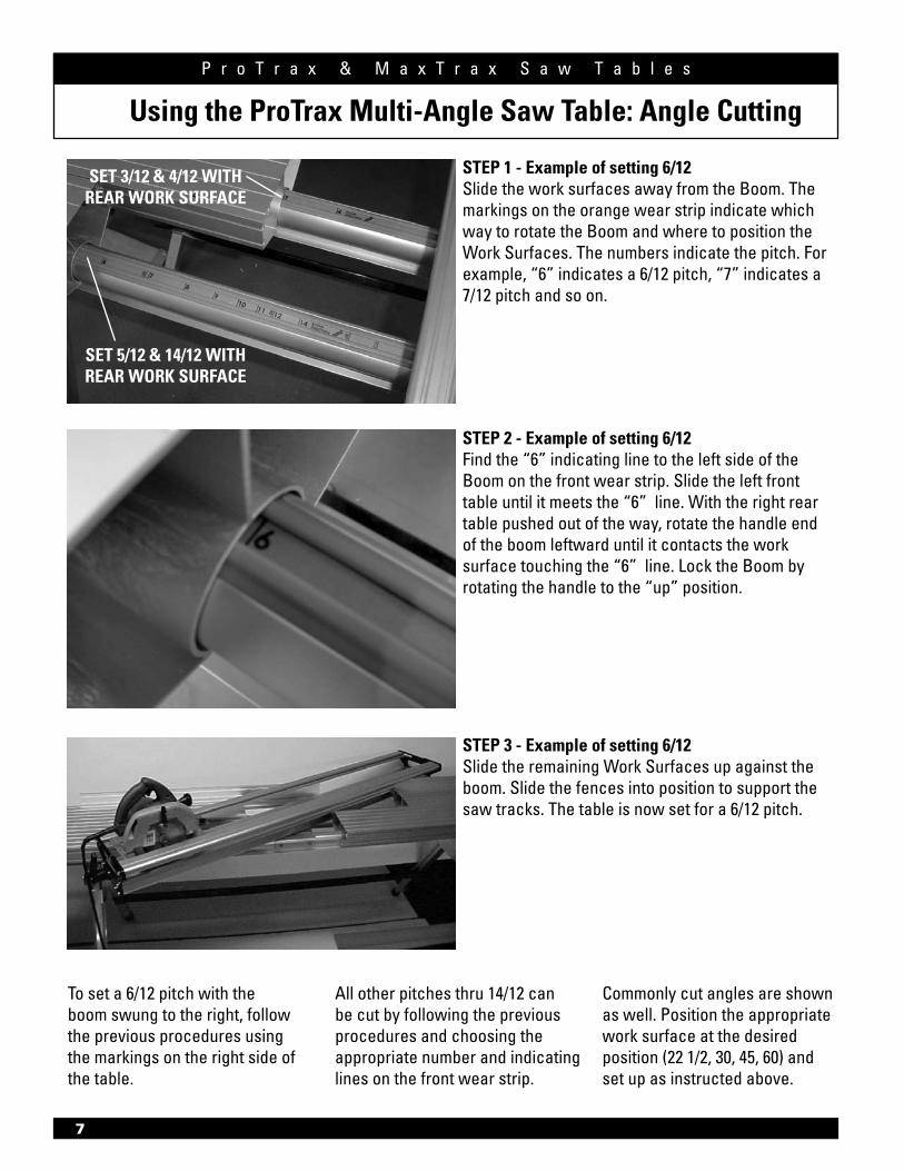
To set a 6/12 pitch with the boom swung to the right, follow the previous procedures using the markings on the right side of the table.
All other pitches thru 14/12 can be cut by following the previous procedures and choosing the appropriate number and indicating lines on the front wear strip.
Commonly cut angles are shown as well. Position the appropriate work surface at the desired position (22 1/2, 30, 45, 60) and set up as instructed above.
STeP 1 - example of setting 6/12Slide the work surfaces away from the Boom. The markings on the orange wear strip indicate which way to rotate the Boom and where to position the Work Surfaces. The numbers indicate the pitch. For example, “6” indicates a 6/12 pitch, “7” indicates a 7/12 pitch and so on.
STeP 2 - example of setting 6/12 Find the “6” indicating line to the left side of the Boom on the front wear strip. Slide the left front table until it meets the “6” line. With the right rear table pushed out of the way, rotate the handle end of the boom leftward until it contacts the work surface touching the “6” line. Lock the Boom by rotating the handle to the “up” position.
STeP 3 - example of setting 6/12 Slide the remaining Work Surfaces up against the boom. Slide the fences into position to support the saw tracks. The table is now set for a 6/12 pitch.
SeT 3/12 & 4/12 wITH reAr work SUrFACe
SeT 5/12 & 14/12 wITH reAr work SUrFACe

P r o T r a x & M a x T r a x S a w T a b l e s
8
Using the ProTrax Multi-Angle Saw Table: Cutting a 3/12 Pitch
3/12 pitch can only be set from the left side of the table.
STeP 1Slide the work surfaces away from the Boom. Find the “3” indicating line on the left rear wear strip. Slide the left rear table until it meets the “3” line. With the left front table pushed out of the way, rotate the handle end of the boom leftward until it contacts the work surface that is touching the “3” line.
STeP 2Push the Boom toward the rear. Move the right rear surface up against the Boom. The black Boom End should be just outside of the right rear work surface to allow material to pass through the Boom. The Maximum material width that can be cut in this position is 9”.
STeP 3Lock the Boom and slide the remaining surfaces and fences into position.
3/12 PITCH

P r o T r a x & M a x T r a x S a w T a b l e s
9
MaxTrax Setup & operating Instructions
Follow Steps 1-5 of “Using the ProTrax Multi-Angle Saw Table: 90� Degree Cuts” (page 6). The MaxTrax has Deck Extenders that need to be against the Boom when cutting. Slide the Deck Extenders up to the Boom as shown in the figure at right.
The MaxTrax Saw Table is designed to be used with the Snap Stand. The setup and operating instructions for the MaxTrax Saw Table are the same as the ProTrax with a few exceptions.
Page 5 of the ProTrax/MaxTrax instructions refer to attaching the optional Deck Extender to saw table. The MaxTrax comes standard with the Deck Extender. These steps are not optional for the MaxTrax and must be followed.
Cutting 90 Degree cuts, Angle cuts, and 3/12 pitches is the same as the ProTrax with the following exceptions:
Using the MaxTrax Multi-Angle Saw Table: 90� Degree Cuts
saw table with oversized work surface
MaxTrax shown with:• Optional Snap Stand™
• Optional Wheel Kit(circular saw not included)
BooM
DeCk
DeCkexTenDer

P r o T r a x & M a x T r a x S a w T a b l e s
10
Using the MaxTrax Saw Table: Angle Cutting and 3/12 Pitch
orIenTATIon oF BooM SUPPorT
wHen BeInG USeD
Follow Steps 1-3 of “Using the ProTrax Multi-Angle Saw Table: Angle Cutting” (page 7) or “Using the ProTrax Multi-Angle Saw Table: Cutting 3/12 Pitch” (page 8). The MaxTrax has Deck Extenders that need to be against the Boom when cutting. Slide the Deck Extenders up to the Boom as shown in the figure at right.
Since the Boom of the MaxTrax is 8 feet long, cutting an angle allows the Boom to flex. Remove the Boom Support from the top of the Boom and install it on the operator side. See figures at left.
BooM SUPPorT on oPerATor SIDe

P r o T r a x & M a x T r a x S a w T a b l e s
Trouble Shooting Your ProTrax and MaxTrax Saw Tables
Item # 11986T4034-L 5/04
29797 Beck Road • Wixom, MI 48393-2834www.tapcoint.com
TAPCO PRODUCTS COMPANYA Division of Tapco International
©2004 Tapco International Corporation
2) Remove the set screw and tighten or loosen the Lock Block to adjust the tension of the handle. Reach under the center plate and hold it to keep it from turning. Rotate the Lock Block 1/6 turn clockwise for a tighter locking assembly, or 1/6 turn counter-clockwise to loosen the tension. Be sure to reinsert the set screw aligned with a flat on the shaft of the Lock Block once the desired setting is achieved. Do not tighten the set screw against the threaded portion of the shaft, or damage will occur.
1) The locking block is preset at the factory. If the handle is difficult to turn, remove the boom and inspect the cam shaft and locking block to be certain they are clean and properly lubricated. Rotate the Lock Block 180 degrees and mount the boom. If the handle is still difficult to turn, proceed to step 2.
11


![Benvenuti | Comune di Vibo Valentia - Schema... · z x z x ó ° > u ä u w y ä t t t á t t ä á > [ ] t ä t t t á t t á x x ï ä](https://img.pdfslide.net/doc/110x75/5fc2bdce95ada2307c5bc307/benvenuti-comune-di-vibo-schema-z-x-z-x-u-u-w-y-t-t-t.jpg)