Embed Size (px)
Citation preview
1
ESCUELA TÉCNICA SUPERIOR DE INGENIERÍA Y SISTEMAS DE
TELECOMUNICACIÓN
PROYECTO FIN DE GRADO
TÍTULO: Design and deployment of wireless networks for drones
control
AUTOR: ………Lijia Cai……
TITULACIÓN: ……Grado en Ingeniería de Sistemas de
Telecomunicación
TUTOR: …………… César Benavente Peces………………………………
DEPARTAMENTO: ………… Teoría de la Señal y Comunicaciones
VºBº
Miembros del Tribunal Calificador:
PRESIDENTE: …… Amador González Crespo
TUTOR: …… César Benavente Peces……………….
SECRETARIO: …… David Osés del Campo………
Fecha de lectura:
Calificación:
El Secretario,

2

3
Agradecimiento:
2013-2017, 4 años han pasado tan rápido como si solo fuera ayer cuando llegué,
todavía recuerdo el primer día cuando llegue a Madrid, con muchas ideas,
ilusiones, y miedos sobre este país que habían dado mil vueltas en mi cabeza antes
de venir.
Juraría que en su momento, no podía ni imaginar que algún día podría dominar
este idioma, poder graduarme de una Universidad Española, conocer tanta gente
tan interesante y compartir mi vida con ellas.
Madrid, en mi diccionario es igual que “segunda ciudad”; Universidad Politécnica
de Madrid es igual que “Donde tengo el orgullo”; mi familia, los amigos y
profesores son igual que las lámparas de mi camino ósculo que me indican, me
iluminan, y me acompañan a caminar con fuerza y esperanza.
Especialmente, quiero agradecer a mí querida familia: 谢谢你们,我亲爱的爸爸
妈妈爷爷奶奶还有小姨,四年在西班牙留学,如果没有你们我也许真的做不到更
好的自己,也不会学会独自面对困难。谢谢你们, 我的任何进步都有你们的功
劳。我爱你们!
刘逸驰, 感谢一路有你。前面的人生会更好!
A mis profesores, muchas gracias por sacar lo mejor de mí y ayudarme a madurar
sanamente:
A César, mi tutor de PFG, también has sido mi mentor de la carrera. Te agradezco
por todos tus esfuerzos para enseñarme no sólo conocimientos técnicos sino
también forma de pensar.
A Juanjo, mi "padre" de la escuela. Gracias por todas ayudas y preocupaciones. He
aprendido muchísimo de ti y eso me sirve para toda la vida.
A Javier Ortega, muchas gracias por tu paciencia y enseñanza. Me has descubierto
el mundo del Radio por primera vez, y haberme dado la oportunidad de aprender
en el grupo de investigación GIRA.
4
A Amador, todavía me acuerdo todas tus tutorías de física, me acuerdo también
cuando me ayudaste para tomar decisión entre Chile y Finlandia. Eres un profesor
muy atento, transmites mucha energía positiva.
A todos mis amigos, especialmente quiero agradecer a Mitu Kamisato: gracias por
siempre estar a mi lado apoyándome, acompañándome a pasar tiempos difíciles.
Gracias por haberme dado una amistad tan maravillosa. Nuestra amistad empezó
en el primer año de la universidad y espero que dure para toda la vida. ¡Te quiero
guapa!
Al final quiero deciros, y también a mí misma:
¡Adelante, no hay mal que por bien no venga!

5
6
Index
1 Introduction .............................................................................................................................. 10
1.1 Objective ......................................................................................................................... 10
1.2 Introduction to wireless communication technologies ..................................... 11
1.3 Summary table: .................................................................................................................. 21
2. Drones technical requirements ..................................................................................... 22
2.1 Different functions of drones: ...................................................................................... 22
2.2 latency ................................................................................................................................... 27
2.3 Jitter ....................................................................................................................................... 28
2.4 bandwidth ............................................................................................................................ 28
3. Coverage analysis- path loss ............................................................................................ 29
3.1 Case of outdoor .................................................................................................................. 29
3.2 Case of indoor environments ....................................................................................... 38
4. Latency study ........................................................................................................................... 44
5. Geolocation ............................................................................................................................... 49
6. Deployment of the drone´s Wireless systems ........................................................ 54
6.1 Mapping and surveying .................................................................................................. 54
6.2 Case of life research ......................................................................................................... 57
6.3 Case of leisure .................................................................................................................... 60
6. Budget ......................................................................................................................................... 62
6.1 software, tool, and technologies implementation ................................................ 62
6.2 labor costs and invested hours .................................................................................... 63
7. Conclusion ................................................................................................................................. 64
8. Biography and references ................................................................................................. 65
7
INDEX OF FIGURES:
Figure 1 piconet explication ............................................................................................................ 13
Figure 2 Scatternet explication ...................................................................................................... 13
Figure 3 Bluetooth characteristic ................................................................................................. 14
Figure 4 SIGFOX network architecture ....................................................................................... 16
Figure 5 Sigfox characteristics ....................................................................................................... 17
Figure 6 3 types of devices can be implemented in Lora 1 ................................................. 18
Figure 7 3 types of devices can be implemented in Lora 2 ................................................. 19
Figure 8 NB-IOT frequency spectrums ........................................................................................ 20
Figure 9 Protocol of zig bee architecture ................................................................................... 20
Figure 10 Architecture of a generic communication system [11, p. 100] ..................... 29
Figure 11 physical situation for plane earth loss.................................................................... 31
Figure 12 path loss in out-door situation (2400MHz).......................................................... 32
Figure 13 : path loss in out-door situation (2000MHz) ....................................................... 33
Figure 14 3D simulation for path loss (height, loss, distance) .......................................... 33
Figure 15 3D simulation for path loss (frequency, loss, distance) ................................... 34
Figure 16 Wi-Fi receive typical sensibility ................................................................................. 35
Figure 17 Wi-Fi path loss .................................................................................................................. 35
Figure 18 3G-path loss in 2140MHz ............................................................................................. 37
Figure 19 LPWA path loss (900MHz) ........................................................................................... 38
Figure 20 structure of the exemplary building ........................................................................ 39
Figure 21 indoors converge with one emitter outside .......................................................... 40
Figure 22 indoors converge simulation two emitters outside ........................................... 41
Figure 23 indoor coverage of Bluetooth with two emitters ............................................... 42
Figure 24 indoor coverage of zigbee with two emitters ...................................................... 43
Figure 25 indoor coverage of Wifi with two emitters ........................................................... 43
Figure 26 Impact of frequency dynamic characteristics on network ............................ 45
Figure 27 cognitive radio graph model ...................................................................................... 46
Figure 28 GPS principle 1 .................................................................................................................. 49
Figure 29 GPS calculation method ................................................................................................ 50
Figure 30 Base station positioning ............................................................................................... 51
Figure 31 LPWA device tracking .................................................................................................... 53
Figure 32 Wi-Fi for 300m coverage simulation ...................................................................... 55
Figure 33 Solution indoor case Zigbee ........................................................................................ 58
Figure 34 Solution indoor case Wi-Fi .......................................................................................... 59
8
INDEX OF TABLES:
Table 1 Technology summary table ....................................................................................... 21
Table 2 Bandwidth requirements table ................................................................................ 29
Table 3 typical receiver sensitivity (2G 3G 4G) ................................................................. 36
Table 4 Sensitivity of receiver (LPWA) ................................................................................. 37
Table 5 license comparison among Technologies ............................................................ 45
Table 6 Comparison of number of channels ....................................................................... 47
Table 7 Geolocation summary .................................................................................................. 53
Table 8 Mapping drones solutions (Cellular) ..................................................................... 56
Table 9 Mapping drones solutions (NB-IoT) ...................................................................... 57
Table 10 Rescue drones solutions (WI-FI) .......................................................................... 59
Table 11 Leisure drones solutions (WI-FI) ......................................................................... 61
Table 12 Leisure drones solutions (Cellular) ..................................................................... 61
Table 13 WI-FI implementation budget ............................................................................... 62
Table 14 Cellular implementation budget ........................................................................... 62
Table 15 software budget .......................................................................................................... 62
Table 16 Labor costs and invested hours ............................................................................ 63
9
ABSTRAT
Flying drones, an unmanned aerial vehicle (UAV), are a type of aircraft which has nobody onboard. The massive growth in the number of connected wireless devices leads to an increasing demand for network connectivity, better performance and larger bandwidth. These technologies have been traditionally applied in UAVs for their control (piloting), but the possibility of incorporate onboard cameras, microphones and sensors requires the use other wireless technologies with the appropriate bandwidth, reliability and range. Due to their excellent performance, UAVs are becoming a useful tool in different disciplines. These devices, sometimes also known as drones, provide multidisciplinary applications in areas such as mapping, rescue, and leisure, which are the main focusing areas in this final year project. The relevance of Drones is referring to improving the human life and society. For instance, drones can do many dangerous or high-risk works instead of doing it by human. This advantage has dramatically reduced the accidents probability. In the field of telecommunication, we are mainly focusing on the information or data transferring part. As we all know, there are two types of communications can transfer the information: wired of wireless. But in our case, which is the communication supporting technology for drones, wireless communication is the right choice strategy. In this final year project, different wireless communications systems will be deeply analyzed and designed for Drones according to their functions and types.
10
1 Introduction
In this chapter we are going to introduce different wireless technologies and analyze their characteristics separately for further detailed study.
1.1 Objective
Today, drones, land, air and amphibians have become common elements in different facets of human activity: military, security, rescue, labor, fun. Remote control and transferring information obtained from sensors (video, audio, temperature, humidity, etc.) is carried out using a wireless link, which must use the appropriate technology to obtain the required performance, which may be different depending on the application, the parameters to register, environmental conditions, autonomy range which requires a careful design of the system. This final year project will analyze and design wireless systems for drones depending on their functionalities, requirements and utilities. For the design of wireless networks and the appropriate selection of technologies, an analysis of different wireless technologies will be carried out, such as Wireless Fidelity (WiFi), ZigBee, cellular network and new innovative technologies such as Lora, Sigfox and NB-IoT , And its challenges to enable wireless communications of drones in different environments. The overall design requirements are aimed at minimizing power consumption, maximizing the range of coverage with as few infrastructures (access points / nodes) as possible, and maximizing bandwidth to enable video transmission. Existing technologies as well as extended use devices will be used to reduce the cost of development and deployment. In order to carry out the execution of the project, it is necessary to perform the following tasks: - To Define and design the potential scenarios in which drones are used. - To Describe the specifications for each scenario: bandwidth, frequency range 2.4GHz-5GHz, autonomy at least 30 Min, and latency time less than 200ms. Analysis of each factor and selection of the best options.

11
- Solutions in contexts of wireless technologies applicable for example xG, Bluetooth, Zigbee, WiFi, others. - To Design of solutions for each scenario - Definition of validation tests - To give the Conclusion - To determine the Cost of development and deployment
1.2 Introduction to wireless communication technologies
Nowadays, among all the technologies in the sector of Telecommunication, wireless technology is one of the biggest contribution parts. Wireless communication has involved the transmission of information over distance without need of wires or any forms of cables (wave guides neither electromagnetic nor optical). This is a big and significant move for the communications revolution. The transmission distance can be few meters; also can be thousands of kilometers depending on the standard and the infrastructures. Closing to our daily life, we have already used many devices applied wireless technologies such as smart mobile phones, GPS, satellite Television etc. Advantages of wireless communication: 1. Enabling the connection of the communication more simple (no help of the
cables). And it enables people to communicate regardless of their location. Also improves the efficiency of work and productivity.
2. Communication has enhanced to convey the information quickly to the consumers. [1]
3. Has more completive price-quality, and is cheaper for the installation and configuration.
Disadvantages of wireless communication: 1. Higher possibility to be attacked by security threats. For example, the personal
information such as passwords are easily viewable by others on the wireless network if they have the intention.
2. Wireless networks usually require many radio signals to power them on. But in some cases if there is not an adequate signal, bandwidth will be constrained. In conclusion, wireless communication has certain limitations for the bandwidth.
Wireless standards and technologies

12
There are many ways to classify wireless communication technology, but in this final year project I have chosen to classify them according to its function. The main reason is to facilitate the subsequent studies of different types of UAVs, and apparently the coverage is an indispensable factor. For the various standards you should highlight the relevant properties which influence the system design decisions.
Wireless Personal Area Networks (WPAN)
Wireless personal area networks are systems that connect two personal or short ranged devices that are located very close together, usually in the same room. They generally have a coverage area of less than 10 m [2] The Bluetooth technology is the main representative one.
General Characteristics: Operates in 2.4 GHz ISM band using Frequency-Hopping 1 MHz bandwidth per channel, all together more than 79 FH channels. ISM channel is an licensed band so that it can guarantee avoiding the interferences. It usually performs 1600 hops per second, with Adaptive Frequency-Hopping (AFH) enabled. Hopping sequence is pseudo-randomly specified by a master. TDD for sending and receiving of the packets are used. The devices can form two types of networks: Piconet and Scatternet. The main difference between two types is the number of device can be connected. In case of more connecting nodes, better coverage we could have. But in the same time, it may cause more time delay. It will be discussed in the chapter 4 (latency).
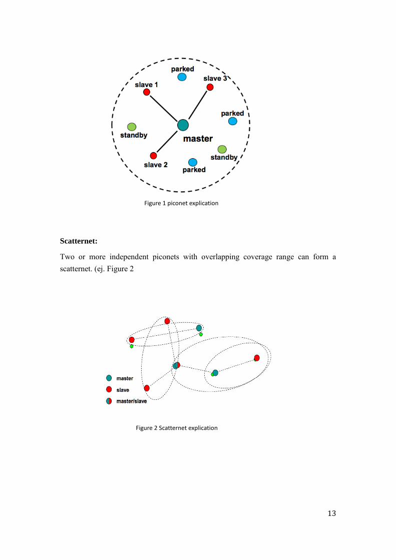
Piconet:
Composed by a set of Bluetooth devices that share the same coverage area and all the devices in a piconet should share the same ‘physical’ channel.
A piconet has at least 2 Bluetooth devices (max. 8) − in the figure1.1, 1 ‘master’ device − 7 simultaneous ‘slave’ devices (max) because of 3-bit addressing to identify a device (more than 200 devices could be parked).
In this case, the master node is responsible for coordinating communication in the piconet. Master gives its clock to his “slave” and device ID in order to monitor them. The active devices will be addressed with 3 bits and the parked with 8 bits.
13
Scatternet:
Two or more independent piconets with overlapping coverage range can form a scatternet. (ej. Figure 2
Figure 1 piconet explication
Figure 2 Scatternet explication

14
Bluetooth
Bluetooth is a two way wireless communication system between devices placed very close to each other. It has proved to be very effective in reducing the clutter of wires. It can connect a mouse to the computer, headphone to an MP3 player etc.
Infrared (IR) wireless communication In Infrared wireless communication systems, data or information is carried over
Infrared waves between two points. The Infrared frequencies lie between the microwave and the visible light ranges in the electromagnetic spectrum. Infrared waves are electromagnetic waves and have wavelength that is longer the wavelength of red light. This technology has a limitation that it can operate only within the line of sight, which means that the straight line path between the transmitter and receiver should be clear of obstructions. These systems are generally used for very small range of distance like TV remote control.
Key innovative technologies considered:
When we talk about drones, in the world of Internet of things, drones can be
counted as a device, a machine. So why could not we deploy a drone control and
information transmission system based on those new innovative technologies into
drones giving them better abilities?
These new technologies are in the categories LPWAN (Low Power WAN), which
both shows their advantages and weak points. And also limits the type of drones
that can implement the wireless Technology. For instance, the more remarkable
Figure 3 Bluetooth characteristic
15
advantage of LPWAN is saving energy. In this case, for the world of drones, can be
a very good commercial point for those Leisure drones and some geography
drawing drones because they do not need the Time-to-Time information either the
latency requirement. But in another way, this advantage can convert into a weak
point if we need drones for lives searching or military use detection.
In this project, we are going to talk about three key LPWAN technologies: Sigfox,
LoRa, and NB-IOT.
Sigfox: SIGFOX provides a cellular network operator that provides solutions for
low-volume content, low-power networking and M2M applications.
From smart meters to essential control nodes, many applications and machines
require long distance connections, and usually the long distance connections can
only choose to use cellular connections (such as GPRS, 3G, 4G, etc.). But this will
have some drawbacks, because the cellular mobile phone system is mainly used in
voice and high-speed data rate applications. For most M2M / IoT applications, they
are not requirement for massive data rate connections, the wireless interface is
complex and increases cost and power consumption.
The SIGFOX network is designed to provide connectivity for a variety of
applications and users. It is not for a particular area, but for a variety of different
types of users generally use. The SIGFOX network performance features are as
follows:
● 140 messages per device per day
● 12 bytes per message (96 bits)
● Wireless throughput up to 100 bits per second
SigFox's main technology, in contrast to mainstream telecom-driven broadband, is
the main ultra-narrow band, because some Internet of Things applications often
only occasionally transmit small amounts of data, so ultra-narrowband
applications are sufficient to cope with transmission needs, Ultra-narrow
frequency technology can be very low power consumption covers a wide range of
areas, more energy-saving, low cost of the purpose, in order to facilitate the
Internet of things to extend battery life and reduce costs.
16
The Sigfox wireless link uses an unauthorized ISM radio frequency band.
Frequency varies according to national regulations, but widely used in Europe
868MHz, 915MHz in the United States.
The density of the units in the SIGFOX network (based on the average distance) is
about 30-50 km in rural areas, and there are often more obstacle and noise
distances in the city that can be reduced to between 3 to10 km.
The entire Sigfox network topology is an extensible, high-capacity network with
very low energy consumption while maintaining a simple and easy-to-deploy star
base-based infrastructure.
SIGFOX uses the standard Binary Phase Shift Keying (BPSK) Binary Phase Shift
Keying method to encode data by changing the radio carrier phase using a very
narrow spectrum. This allows the receiver to listen on only a small portion of the
spectrum and reduce the impact of noise. SIGFOX requires an inexpensive terminal
RF chip and an advanced base station management network.
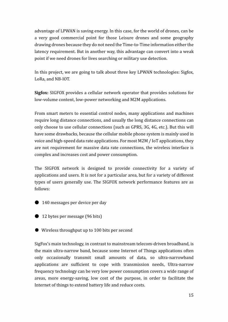
SIGFOX network architecture:
Figure 4 SIGFOX network architecture
SIGFOX has a two-way communication function, communication is often from the
terminal to the base station to send better, but from the base station back to the
terminal its performance is limited, down to have fewer link budget, this is because
17
the terminal to accept Sensitivity is better than base station.
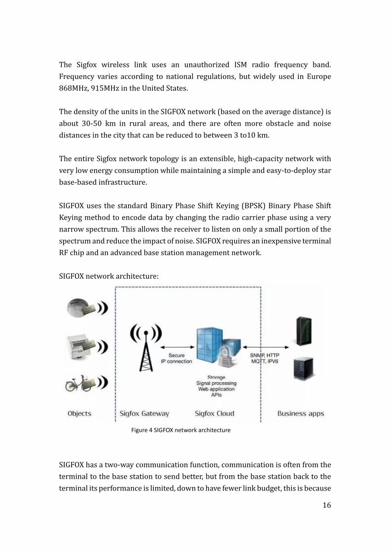
Figure 5 Sigfox characteristics
According to the Sigfox characteristics, we can clearly see the key points of this
technology are: long range (coverage), low battery consumption, limitation for the
video transmission.
LoRa : LoRa as a wireless technology, based on the Sub-GHz band to make it easier
to communicate with the lower power consumption, can be used by battery-
powered or other energy collection way of power supply. Lower data rates also
extend battery life and increase network capacity. LoRa signal on the building
penetration is also very strong. LoRa have technical features more suitable for low-
cost large-scale Internet of things deployment. [1]
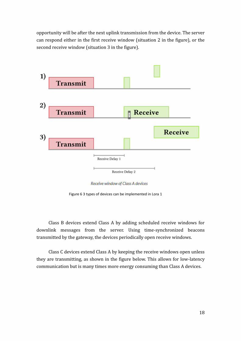
3 types of devices can be implemented in Lora:
Class A devices support a bi-directional communication between a device and a
gateway. UL messages (from the device to the server) can be sent at any time
(randomly). As presents in the figure, the device then opens two receive windows
at specified times (1s and 2s) after an uplink transmission. If the server does not
respond in either of these receive windows (situation 1 in the figure), the next
18
opportunity will be after the next uplink transmission from the device. The server
can respond either in the first receive window (situation 2 in the figure), or the
second receive window (situation 3 in the figure).
Figure 6 3 types of devices can be implemented in Lora 1
Class B devices extend Class A by adding scheduled receive windows for
downlink messages from the server. Using time-synchronized beacons
transmitted by the gateway, the devices periodically open receive windows.
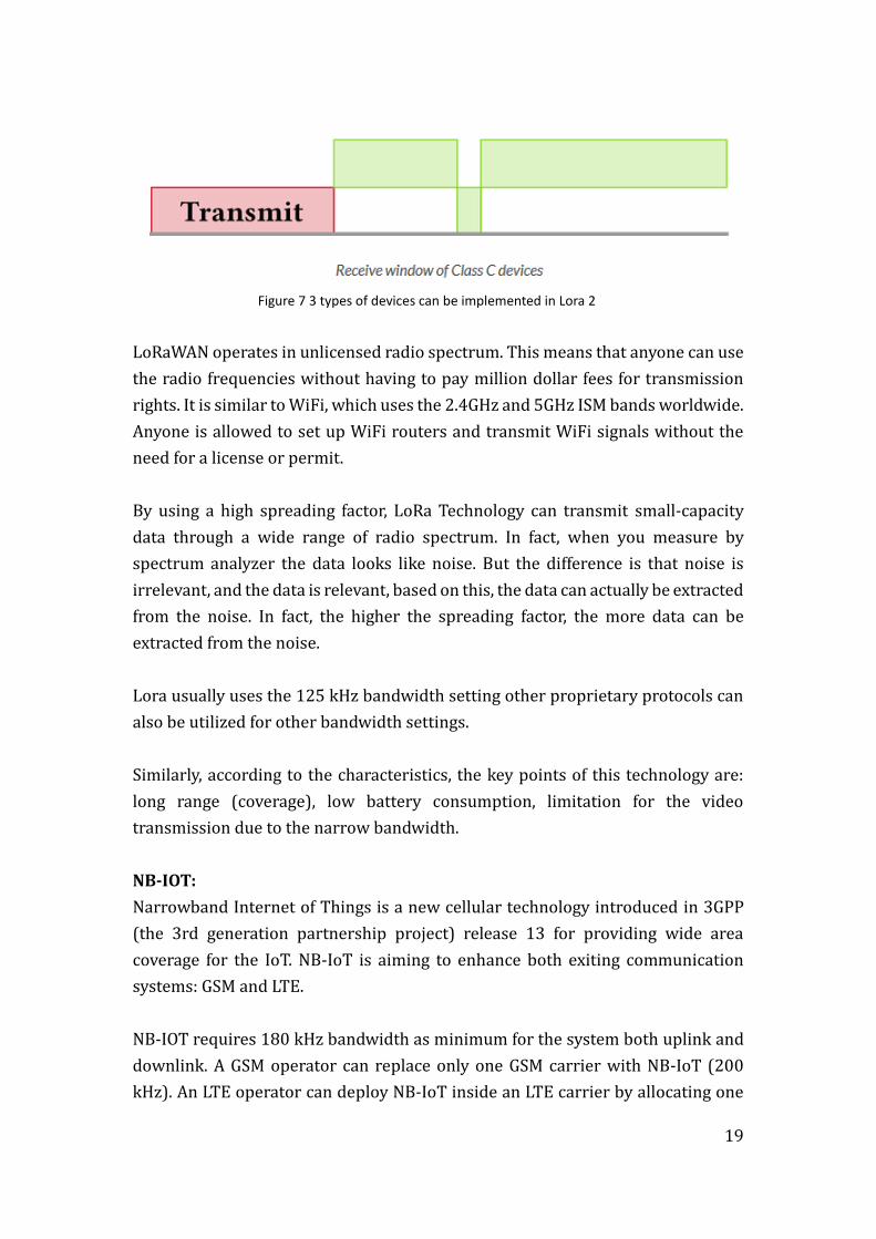
Class C devices extend Class A by keeping the receive windows open unless
they are transmitting, as shown in the figure below. This allows for low-latency
communication but is many times more energy consuming than Class A devices.
19
Figure 7 3 types of devices can be implemented in Lora 2
LoRaWAN operates in unlicensed radio spectrum. This means that anyone can use
the radio frequencies without having to pay million dollar fees for transmission
rights. It is similar to WiFi, which uses the 2.4GHz and 5GHz ISM bands worldwide.
Anyone is allowed to set up WiFi routers and transmit WiFi signals without the
need for a license or permit.
By using a high spreading factor, LoRa Technology can transmit small-capacity
data through a wide range of radio spectrum. In fact, when you measure by
spectrum analyzer the data looks like noise. But the difference is that noise is
irrelevant, and the data is relevant, based on this, the data can actually be extracted
from the noise. In fact, the higher the spreading factor, the more data can be
extracted from the noise.
Lora usually uses the 125 kHz bandwidth setting other proprietary protocols can
also be utilized for other bandwidth settings.
Similarly, according to the characteristics, the key points of this technology are:
long range (coverage), low battery consumption, limitation for the video
transmission due to the narrow bandwidth.
NB-IOT:
Narrowband Internet of Things is a new cellular technology introduced in 3GPP
(the 3rd generation partnership project) release 13 for providing wide area
coverage for the IoT. NB-IoT is aiming to enhance both exiting communication
systems: GSM and LTE.
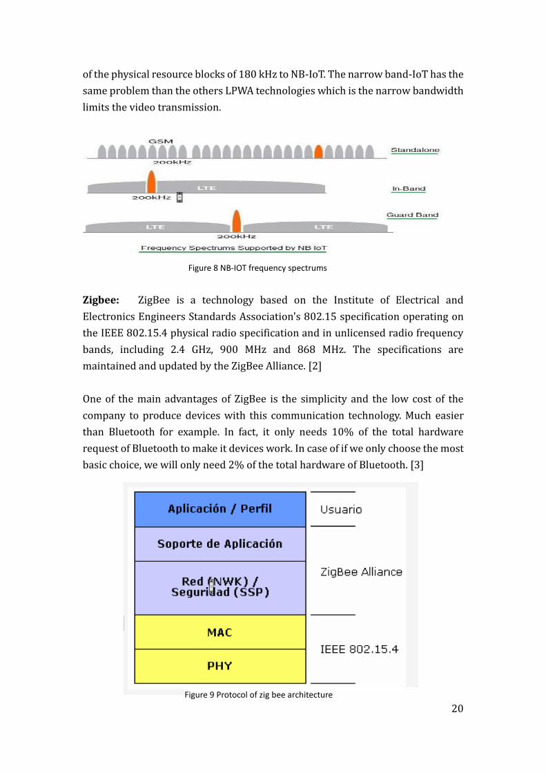
NB-IOT requires 180 kHz bandwidth as minimum for the system both uplink and
downlink. A GSM operator can replace only one GSM carrier with NB-IoT (200
kHz). An LTE operator can deploy NB-IoT inside an LTE carrier by allocating one
20
of the physical resource blocks of 180 kHz to NB-IoT. The narrow band-IoT has the
same problem than the others LPWA technologies which is the narrow bandwidth
limits the video transmission.
Figure 8 NB-IOT frequency spectrums
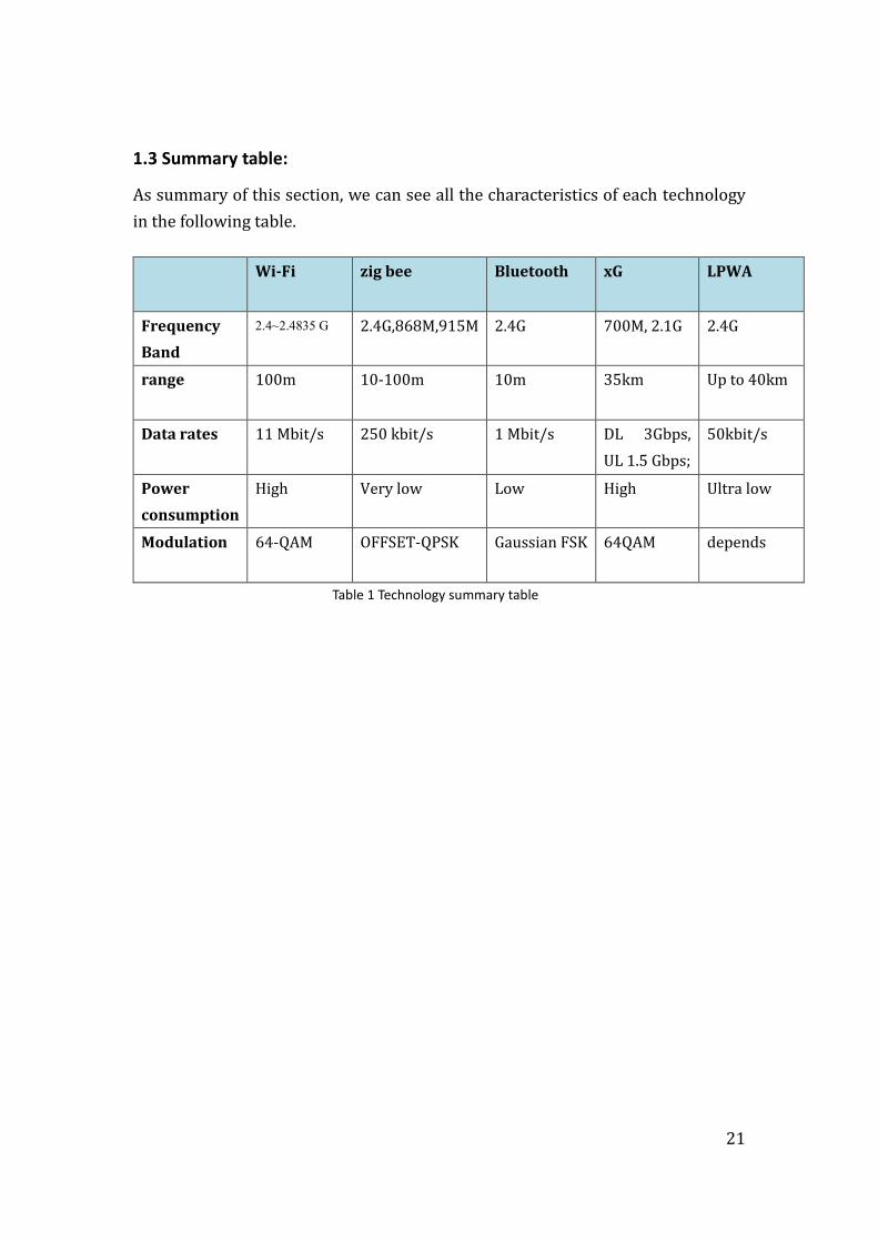
Zigbee: ZigBee is a technology based on the Institute of Electrical and
Electronics Engineers Standards Association's 802.15 specification operating on
the IEEE 802.15.4 physical radio specification and in unlicensed radio frequency
bands, including 2.4 GHz, 900 MHz and 868 MHz. The specifications are
maintained and updated by the ZigBee Alliance. [2]
One of the main advantages of ZigBee is the simplicity and the low cost of the
company to produce devices with this communication technology. Much easier
than Bluetooth for example. In fact, it only needs 10% of the total hardware
request of Bluetooth to make it devices work. In case of if we only choose the most
basic choice, we will only need 2% of the total hardware of Bluetooth. [3]
Figure 9 Protocol of zig bee architecture
21
1.3 Summary table:
As summary of this section, we can see all the characteristics of each technology
in the following table.
Wi-Fi zig bee Bluetooth xG LPWA
Frequency
Band
2.4~2.4835 G 2.4G,868M,915M 2.4G 700M, 2.1G 2.4G
range 100m 10-100m 10m 35km Up to 40km
Data rates 11 Mbit/s 250 kbit/s 1 Mbit/s DL 3Gbps,
UL 1.5 Gbps;
50kbit/s
Power
consumption
High Very low Low High Ultra low
Modulation 64-QAM OFFSET-QPSK Gaussian FSK 64QAM depends
Table 1 Technology summary table
22
2. Drones technical requirements
UAS (Unmanned Aircraft Systems), known as drones, now are standing in the
middle of the global stage of internet evolution application area. For us, as
engineers in telecommunications, the main focus is the implementation of the
wireless communication systems enabling the drone´s functionality.
The key challenges in the design of UAS are the large distances communicating
ability and capacity of high-speed transmission. This also affects the availability of
radio frequency spectrum and the performance of the data link (noise and
interferences).
As highlighted above, to achieve this, we need focus on these factors depending on
different functions: the signal coverage, power of the transmission, sensibility of
receiver, distance range and latency.
2.1 Different functions of drones:
Mapping and surveying: creating 3D maps from UAV, usually the camera is
mounted on the drone and is pointed vertically towards the ground in order to
capture the ground figure. For measuring the height of points the UAV usually
needs a laser scanner, which can capture hundreds of square kilometers in a single
day. Normally by measuring 10-80 points per square meter, a digital model or map
can be created with details. This accuracy of the measurements can allow the UAV
used in any industrial such as: [4]
3D building models designing
Plane metric features
Forestry Management and Planning
Flood modeling and pollution modeling
Urban and transport planning
Cellular network planning
Nowadays out market already has many remarkable Mapping drones: DJI
Phantom3 professional, DJI Mavic, SenseFly eBee Pro Mapping UAV. To be more
23
specific, I pick the main information (features) of the each product for the further
comparison.
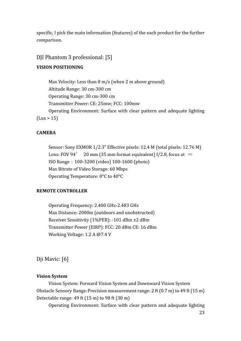
DJI Phantom 3 professional: [5]
VISION POSITIONING
Max Velocity: Less than 8 m/s (when 2 m above ground)
Altitude Range: 30 cm-300 cm
Operating Range: 30 cm-300 cm
Transmitter Power: CE: 25mw; FCC: 100mw
Operating Environment: Surface with clear pattern and adequate lighting
(Lux > 15)
CAMERA
Sensor: Sony EXMOR 1/2.3” Effective pixels: 12.4 M (total pixels: 12.76 M)
Lens: FOV 94° 20 mm (35 mm format equivalent) f/2.8, focus at ∞
ISO Range:100-3200 (video) 100-1600 (photo)
Max Bitrate of Video Storage: 60 Mbps
Operating Temperature: 0°C to 40°C
REMOTE CONTROLLER
Operating Frequency: 2.400 GHz-2.483 GHz
Max Distance: 2000m (outdoors and unobstructed)
Receiver Sensitivity (1%PER): -101 dBm ±2 dBm
Transmitter Power (EIRP): FCC: 20 dBm CE: 16 dBm
Working Voltage: 1.2 A @7.4 V
Dji Mavic: [6]
Vision System
Vision System: Forward Vision System and Downward Vision System
Obstacle Sensory Range: Precision measurement range: 2 ft (0.7 m) to 49 ft (15 m)
Detectable range: 49 ft (15 m) to 98 ft (30 m)
Operating Environment: Surface with clear pattern and adequate lighting
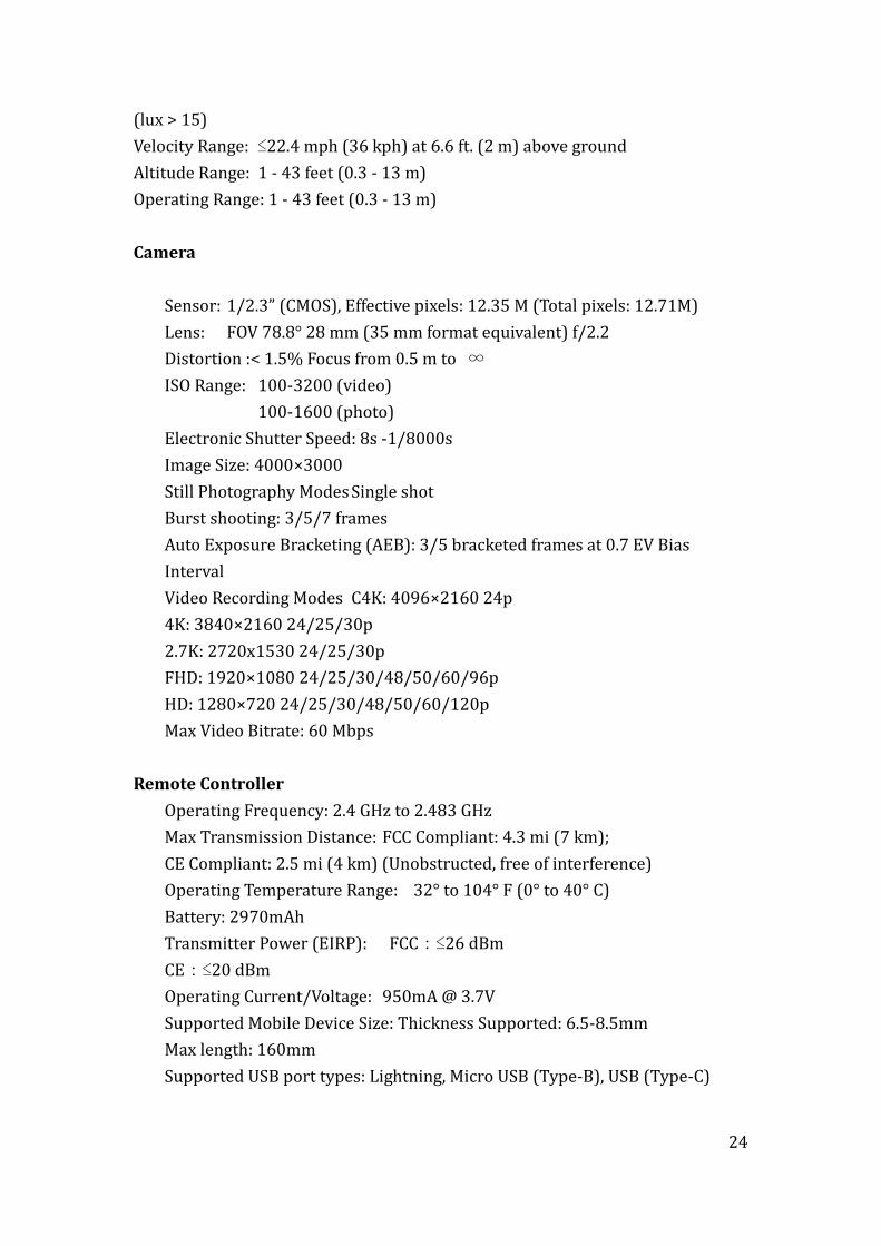
24
(lux > 15)
Velocity Range: ≤22.4 mph (36 kph) at 6.6 ft. (2 m) above ground
Altitude Range: 1 - 43 feet (0.3 - 13 m)
Operating Range: 1 - 43 feet (0.3 - 13 m)
Camera
Sensor: 1/2.3” (CMOS), Effective pixels: 12.35 M (Total pixels: 12.71M)
Lens: FOV 78.8° 28 mm (35 mm format equivalent) f/2.2
Distortion :< 1.5% Focus from 0.5 m to ∞
ISO Range: 100-3200 (video)
100-1600 (photo)
Electronic Shutter Speed: 8s -1/8000s
Image Size: 4000×3000
Still Photography Modes Single shot
Burst shooting: 3/5/7 frames
Auto Exposure Bracketing (AEB): 3/5 bracketed frames at 0.7 EV Bias
Interval
Video Recording Modes C4K: 4096×2160 24p
4K: 3840×2160 24/25/30p
2.7K: 2720x1530 24/25/30p
FHD: 1920×1080 24/25/30/48/50/60/96p
HD: 1280×720 24/25/30/48/50/60/120p
Max Video Bitrate: 60 Mbps
Remote Controller
Operating Frequency: 2.4 GHz to 2.483 GHz
Max Transmission Distance: FCC Compliant: 4.3 mi (7 km);
CE Compliant: 2.5 mi (4 km) (Unobstructed, free of interference)
Operating Temperature Range: 32° to 104° F (0° to 40° C)
Battery: 2970mAh
Transmitter Power (EIRP): FCC:≤26 dBm
CE:≤20 dBm
Operating Current/Voltage: 950mA @ 3.7V
Supported Mobile Device Size: Thickness Supported: 6.5-8.5mm
Max length: 160mm
Supported USB port types: Lightning, Micro USB (Type-B), USB (Type-C)
25
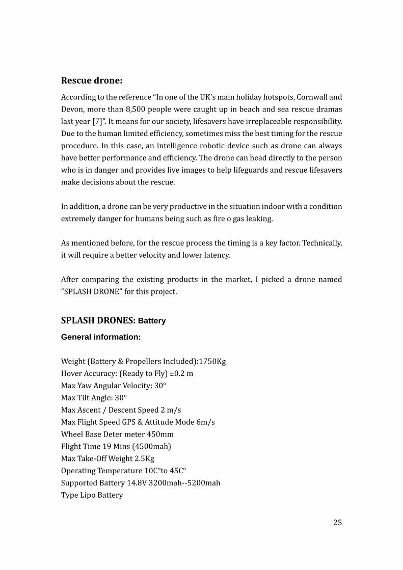
Rescue drone:
According to the reference “In one of the UK's main holiday hotspots, Cornwall and
Devon, more than 8,500 people were caught up in beach and sea rescue dramas
last year [7]”. It means for our society, lifesavers have irreplaceable responsibility.
Due to the human limited efficiency, sometimes miss the best timing for the rescue
procedure. In this case, an intelligence robotic device such as drone can always
have better performance and efficiency. The drone can head directly to the person
who is in danger and provides live images to help lifeguards and rescue lifesavers
make decisions about the rescue.
In addition, a drone can be very productive in the situation indoor with a condition
extremely danger for humans being such as fire o gas leaking.
As mentioned before, for the rescue process the timing is a key factor. Technically,
it will require a better velocity and lower latency.
After comparing the existing products in the market, I picked a drone named
“SPLASH DRONE” for this project.
SPLASH DRONES: Battery & Transmitter Specification
General information:
Weight (Battery & Propellers Included):1750Kg
Hover Accuracy: (Ready to Fly) ±0.2 m
Max Yaw Angular Velocity: 30°
Max Tilt Angle: 30°
Max Ascent / Descent Speed 2 m/s
Max Flight Speed GPS & Attitude Mode 6m/s
Wheel Base Deter meter 450mm
Flight Time 19 Mins (4500mah)
Max Take-Off Weight 2.5Kg
Operating Temperature 10C°to 45C°
Supported Battery 14.8V 3200mah--5200mah
Type Lipo Battery
26
Battery
Capacity 14.8V 4500mah
Charging Environment Range 0C°to 40C°
Charging Time 60minutes
Remote Controller
Weight 390g
Operating Frequency 2405 to 2475HMZ
Communication Distance (Open Area) 1.0 KM
Receiver Sensitivity (1%PER) -105dbm
Working Current/Voltage 120 mA
Battery 1.5V AA*4
Channels 6 channels
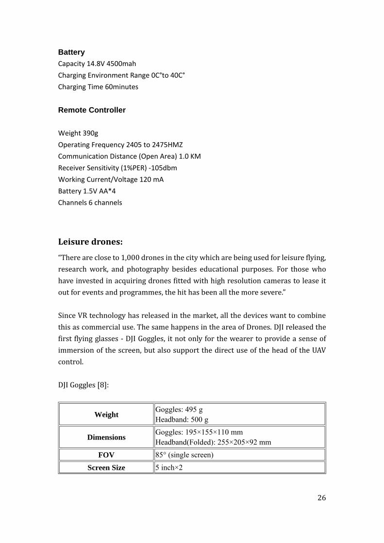
Leisure drones:
“There are close to 1,000 drones in the city which are being used for leisure flying,
research work, and photography besides educational purposes. For those who
have invested in acquiring drones fitted with high resolution cameras to lease it
out for events and programmes, the hit has been all the more severe.”
Since VR technology has released in the market, all the devices want to combine
this as commercial use. The same happens in the area of Drones. DJI released the
first flying glasses - DJI Goggles, it not only for the wearer to provide a sense of
immersion of the screen, but also support the direct use of the head of the UAV
control.
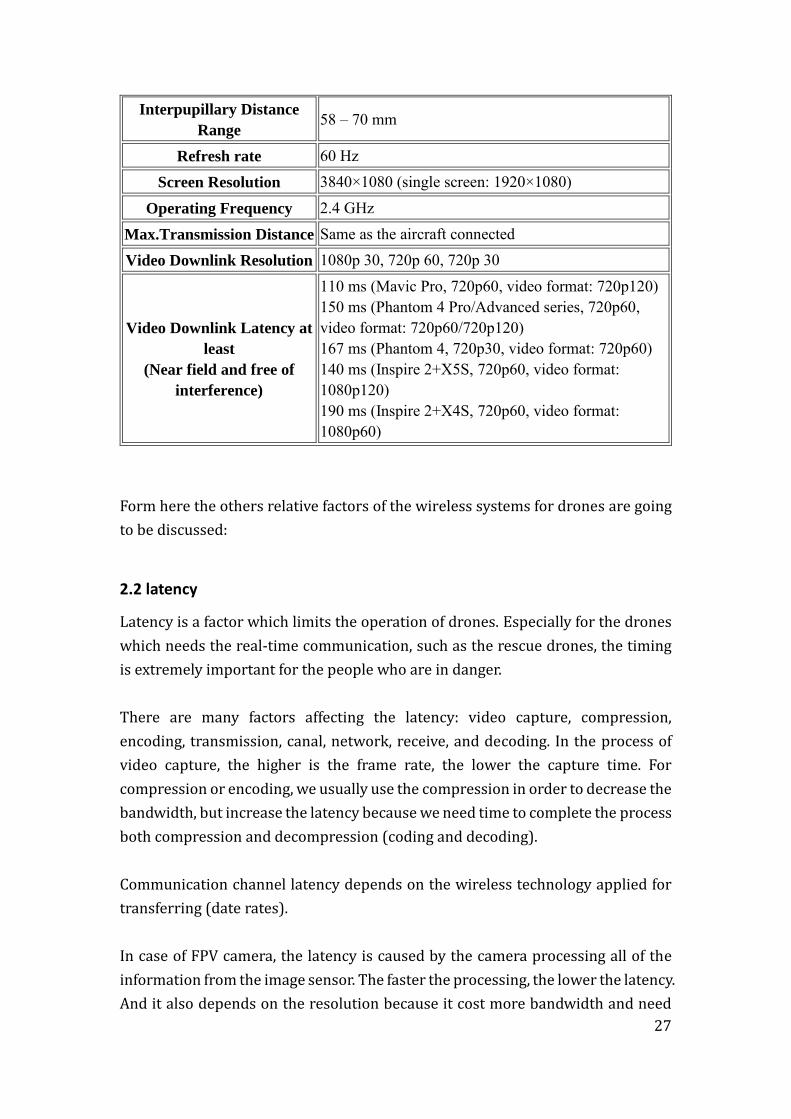
DJI Goggles [8]:
Weight Goggles: 495 g Headband: 500 g
Dimensions Goggles: 195×155×110 mm Headband(Folded): 255×205×92 mm
FOV 85° (single screen)
Screen Size 5 inch×2
27
Interpupillary Distance
Range 58 – 70 mm
Refresh rate 60 Hz Screen Resolution 3840×1080 (single screen: 1920×1080)
Operating Frequency 2.4 GHz Max.Transmission Distance Same as the aircraft connected Video Downlink Resolution 1080p 30, 720p 60, 720p 30
Video Downlink Latency at
least
(Near field and free of
interference)
110 ms (Mavic Pro, 720p60, video format: 720p120) 150 ms (Phantom 4 Pro/Advanced series, 720p60, video format: 720p60/720p120) 167 ms (Phantom 4, 720p30, video format: 720p60) 140 ms (Inspire 2+X5S, 720p60, video format: 1080p120) 190 ms (Inspire 2+X4S, 720p60, video format: 1080p60)
Form here the others relative factors of the wireless systems for drones are going
to be discussed:
2.2 latency
Latency is a factor which limits the operation of drones. Especially for the drones
which needs the real-time communication, such as the rescue drones, the timing
is extremely important for the people who are in danger.
There are many factors affecting the latency: video capture, compression,
encoding, transmission, canal, network, receive, and decoding. In the process of
video capture, the higher is the frame rate, the lower the capture time. For
compression or encoding, we usually use the compression in order to decrease the
bandwidth, but increase the latency because we need time to complete the process
both compression and decompression (coding and decoding).
Communication channel latency depends on the wireless technology applied for
transferring (date rates).
In case of FPV camera, the latency is caused by the camera processing all of the
information from the image sensor. The faster the processing, the lower the latency.
And it also depends on the resolution because it cost more bandwidth and need
28
more capacity of transmitter.
As discussed previously in the case of leisure, the latency is hardly noticeable with
general flying, even though normally it will have 100ms delay when flying at 50
mph which means your drone will travel about 1.7m before you receive the video.
As an advantage, most FPV cameras have a lower latency around 40ms, while the
normal cameras will have a latency of 140ms or more. [9]
2.3 Jitter
Jitter is an undesirable effect frequently caused by the inherent tendencies of
TCP/IP networks and components.
Jitter can be defined as a variation in the delay of received packets. In the beginning
all the steady stream of packets are sent in a continuous stream and be spaced
evenly apart. But later because of the network congestion, configuration errors or
the incorrect queuing etc., the delay space between packets can be varied instead
of being constant.
So, when a receiver receives a stream, the first priority process is detecting if there
are any jitter effect. In case of confirmative, the stream should be compensated.
In order to overcoming the Jitter, the Cisco has set up a buffer ”jitter buffer”on the
route way before the signal entry the receiving channel. [10]
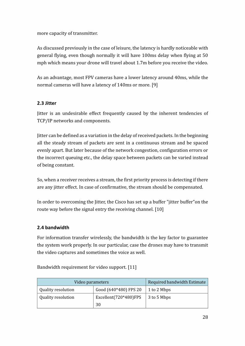
2.4 bandwidth
For information transfer wirelessly, the bandwidth is the key factor to guarantee
the system work properly. In our particular, case the drones may have to transmit
the video captures and sometimes the voice as well.
Bandwidth requirement for video support. [11]
Video parameters Required bandwidth Estimate
Quality resolution Good (640*480) FPS 20 1 to 2 Mbps
Quality resolution Excellent(720*480)FPS
30
3 to 5 Mbps

29
Quality resolution Excellent(1280*800)FPS
30
7 to 9 Mbps
Table 2 Bandwidth requirements table
3. Coverage analysis- path loss
The drone´s control system normally works remotely, which refers to the coverage
capacity of each communication link technology. Moreover, it also limits the
mobility of the drones. Therefore, the coverage is an extremely important factor
for the wireless system design.
Figure 10 Architecture of a generic communication system [12, p. 100]
The basic communication system consists of 3 parts: transmitter, communication
channel and receiver. When we talking about converge, refers the study for the
path loss of the transmission channel.
In this chapter I am mainly focusing on two different cases: outdoor and indoor.
For that, the implementation of Matlab makes the simulation more visually and
more directly.
3.1 Case of outdoor
The path loss between transmitter and receiver antennas is usually expressed in
decibels and includes all the factors which may cause the path loss.
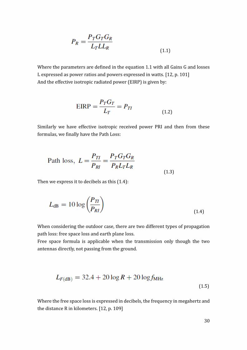
In order to calculate the power at the receiver, we have these formulas:
30
(1.1)
Where the parameters are defined in the equation 1.1 with all Gains G and losses
L expressed as power ratios and powers expressed in watts. [12, p. 101]
And the effective isotropic radiated power (EIRP) is given by:
(1.2)
Similarly we have effective isotropic received power PRI and then from these
formulas, we finally have the Path Loss:
(1.3)
Then we express it to decibels as this (1.4):
(1.4)
When considering the outdoor case, there are two different types of propagation
path loss: free space loss and earth plane loss.
Free space formula is applicable when the transmission only though the two
antennas directly, not passing from the ground.
(1.5)
Where the free space loss is expressed in decibels, the frequency in megahertz and
the distance R in kilometers. [12, p. 109]

31
Another fundamental propagation type is plane earth loss, in here both two
antennas are situated above a plane earth, the communication path can be directly
or through the reflection of the plane earth as the figure below:
Figure 11 physical situation for plane earth loss
According to the formulas and calculation, we have the following final formula for
the plane earth path loss:
(1.6)
Where ℎ𝑚 and ℎ𝑏 are the height of the two antennas and 𝑟 is the distance
between both of them. [12, p. 111]
After learning all the formulas above, in order to implement it into my project, I
coded in Matlab and figured it (Annex 1)
For the convenience of the simulation, I have chosen those parameters as an
example:
d=1e1: 10: 1e5; d_km=d. / 1000; %di s t ance i n Km. f =2400e6; %f =2400 Mhz
32
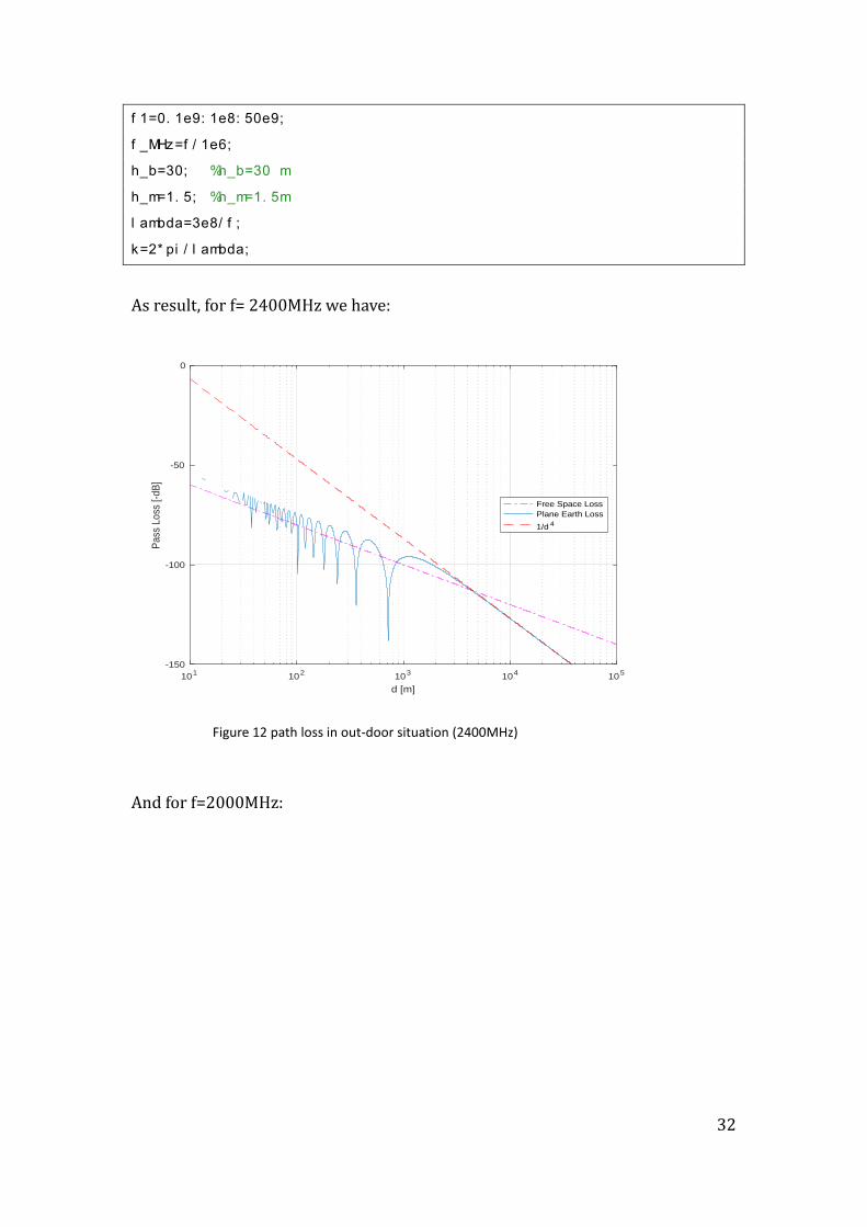
f 1=0. 1e9: 1e8: 50e9; f _MHz=f / 1e6; h_b=30; %h_b=30 m h_m=1. 5; %h_m=1. 5m l ambda=3e8/ f ; k=2* pi / l ambda;
As result, for f= 2400MHz we have:
And for f=2000MHz:
101
102
103
104
105
d [m]
-150
-100
-50
0
Pass
Lo
ss [-d
B]
Free Space Loss
Plane Earth Loss
1/d 4
Figure 12 path loss in out-door situation (2400MHz)
33
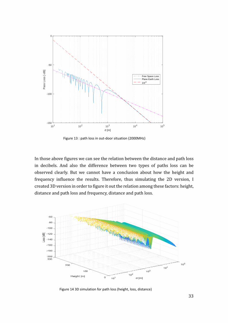
Figure 13 : path loss in out-door situation (2000MHz)
In those above figures we can see the relation between the distance and path loss
in decibels. And also the difference between two types of paths loss can be
observed clearly. But we cannot have a conclusion about how the height and
frequency influence the results. Therefore, thus simulating the 2D version, I
created 3D version in order to figure it out the relation among these factors: height,
distance and path loss and frequency, distance and path loss.
Figure 14 3D simulation for path loss (height, loss, distance)
101
102
103
104
105
d [m]
-150
-100
-50
0
Pass L
oss [-d
B]
Free Space Loss
Plane Earth Loss
1/d 4
34
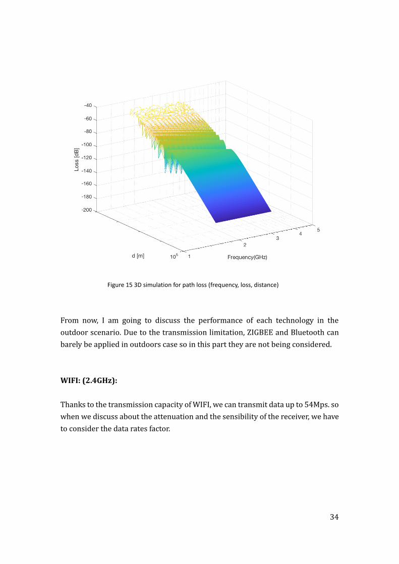
Figure 15 3D simulation for path loss (frequency, loss, distance)
From now, I am going to discuss the performance of each technology in the
outdoor scenario. Due to the transmission limitation, ZIGBEE and Bluetooth can
barely be applied in outdoors case so in this part they are not being considered.
WIFI: (2.4GHz):
Thanks to the transmission capacity of WIFI, we can transmit data up to 54Mps. so
when we discuss about the attenuation and the sensibility of the receiver, we have
to consider the data rates factor.
35
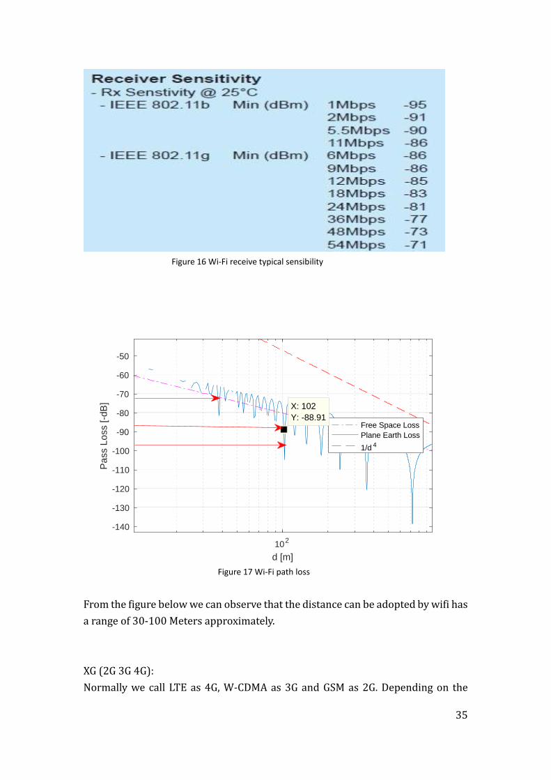
Figure 16 Wi-Fi receive typical sensibility
Figure 17 Wi-Fi path loss
From the figure below we can observe that the distance can be adopted by wifi has
a range of 30-100 Meters approximately.
XG (2G 3G 4G):
Normally we call LTE as 4G, W-CDMA as 3G and GSM as 2G. Depending on the
102
d [m]
-140
-130
-120
-110
-100
-90
-80
-70
-60
-50
Pa
ss L
oss [
-dB
]
Free Space Loss
Plane Earth Loss
1/d 4
X: 102
Y: -88.91
36
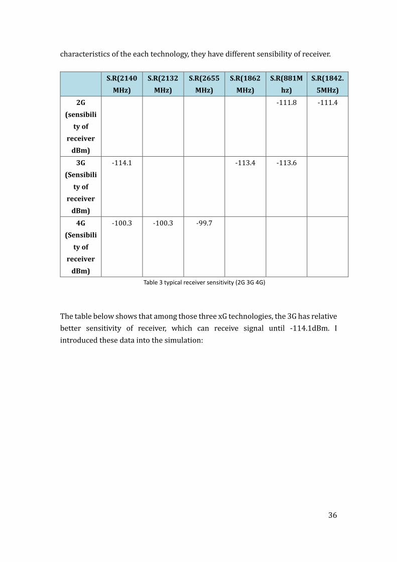
characteristics of the each technology, they have different sensibility of receiver.
S.R(2140
MHz)
S.R(2132
MHz)
S.R(2655
MHz)
S.R(1862
MHz)
S.R(881M
hz)
S.R(1842.
5MHz)
2G
(sensibili
ty of
receiver
dBm)
-111.8 -111.4
3G
(Sensibili
ty of
receiver
dBm)
-114.1 -113.4 -113.6
4G
(Sensibili
ty of
receiver
dBm)
-100.3 -100.3 -99.7
Table 3 typical receiver sensitivity (2G 3G 4G)
The table below shows that among those three xG technologies, the 3G has relative
better sensitivity of receiver, which can receive signal until -114.1dBm. I
introduced these data into the simulation:
37
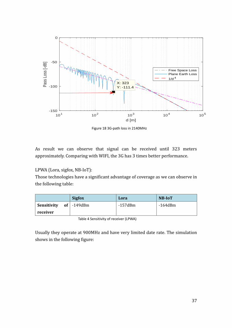
Figure 18 3G-path loss in 2140MHz
As result we can observe that signal can be received until 323 meters
approximately. Comparing with WIFI, the 3G has 3 times better performance.
LPWA (Lora, sigfox, NB-IoT):
Those technologies have a significant advantage of coverage as we can observe in
the following table:
Sigfox Lora NB-IoT
Sensitivity of
receiver
-149dBm -157dBm -164dBm
Table 4 Sensitivity of receiver (LPWA)
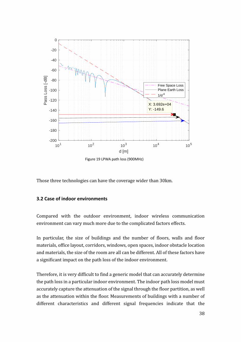
Usually they operate at 900MHz and have very limited date rate. The simulation
shows in the following figure:
101
102
103
104
105
d [m]
-150
-100
-50
0
Pas
s Lo
ss [-
dB]
Free Space Loss
Plane Earth Loss
1/d 4
X: 323
Y: -111.4
38
Figure 19 LPWA path loss (900MHz)
Those three technologies can have the coverage wider than 30km.
3.2 Case of indoor environments
Compared with the outdoor environment, indoor wireless communication
environment can vary much more due to the complicated factors effects.
In particular, the size of buildings and the number of floors, walls and floor
materials, office layout, corridors, windows, open spaces, indoor obstacle location
and materials, the size of the room are all can be different. All of these factors have
a significant impact on the path loss of the indoor environment.
Therefore, it is very difficult to find a generic model that can accurately determine
the path loss in a particular indoor environment. The indoor path loss model must
accurately capture the attenuation of the signal through the floor partition, as well
as the attenuation within the floor. Measurements of buildings with a number of
different characteristics and different signal frequencies indicate that the
101
102
103
104
105
d [m]
-200
-180
-160
-140
-120
-100
-80
-60
-40
-20
0
Pass L
oss [-d
B]
Free Space Loss
Plane Earth Loss
1/d 4
X: 3.692e+04
Y: -149.6
39
attenuation of the floor signal across the first floor is greatest; and the signal
attenuation across the subsequent floor is relatively small.
For 2000 MHz of frequency, if the receiver is placed at a distance between the
transmitter and the transmitter, the signal attenuation range is 10-20 dB, and in
the next three floors, the floor wear loss is 6 -10dB, and in the fourth floor, the
signal through the loss of less. If the frequency of the signal is higher, then the
greater attenuation performance passes through the floor. The increase in the
number of floors passing through the attenuation floor results in a decrease in the
attenuation of the single layer through the reflection of the building and the
reflection of the adjacent building. The difference between the material and the
dielectric properties of the adjacent compartments is also very large, so that the
variation of the compartmental wear loss is also large.
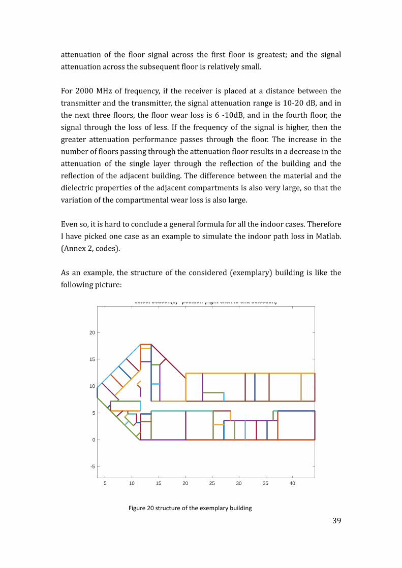
Even so, it is hard to conclude a general formula for all the indoor cases. Therefore
I have picked one case as an example to simulate the indoor path loss in Matlab.
(Annex 2, codes).
As an example, the structure of the considered (exemplary) building is like the
following picture:
Figure 20 structure of the exemplary building
5 10 15 20 25 30 35 40
-5
0
5
10
15
20
select beacon(s) ' position (right click to end selection)
40
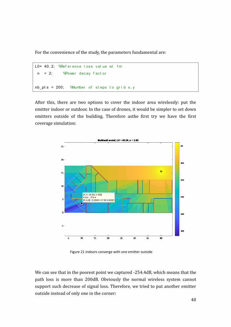
For the convenience of the study, the parameters fundamental are:
L0= 40. 2; %Ref er ence l oss val ue at 1m n = 2; %Power decay f ac t or nb_pt s = 200; %Number of s t eps t o gr i d x , y
After this, there are two options to cover the indoor area wirelessly: put the
emitter indoor or outdoor. In the case of drones, it would be simpler to set down
emitters outside of the building. Therefore asthe first try we have the first
coverage simulation:
Figure 21 indoors converge with one emitter outside
We can see that in the poorest point we captured -254.4dB, which means that the
path loss is more than 200dB. Obviously the normal wireless system cannot
support such decrease of signal loss. Therefore, we tried to put another emitter
outside instead of only one in the corner:
41
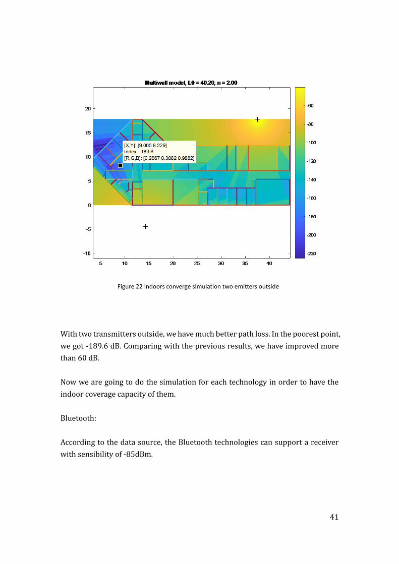
Figure 22 indoors converge simulation two emitters outside
With two transmitters outside, we have much better path loss. In the poorest point,
we got -189.6 dB. Comparing with the previous results, we have improved more
than 60 dB.
Now we are going to do the simulation for each technology in order to have the
indoor coverage capacity of them.
Bluetooth:
According to the data source, the Bluetooth technologies can support a receiver
with sensibility of -85dBm.
42
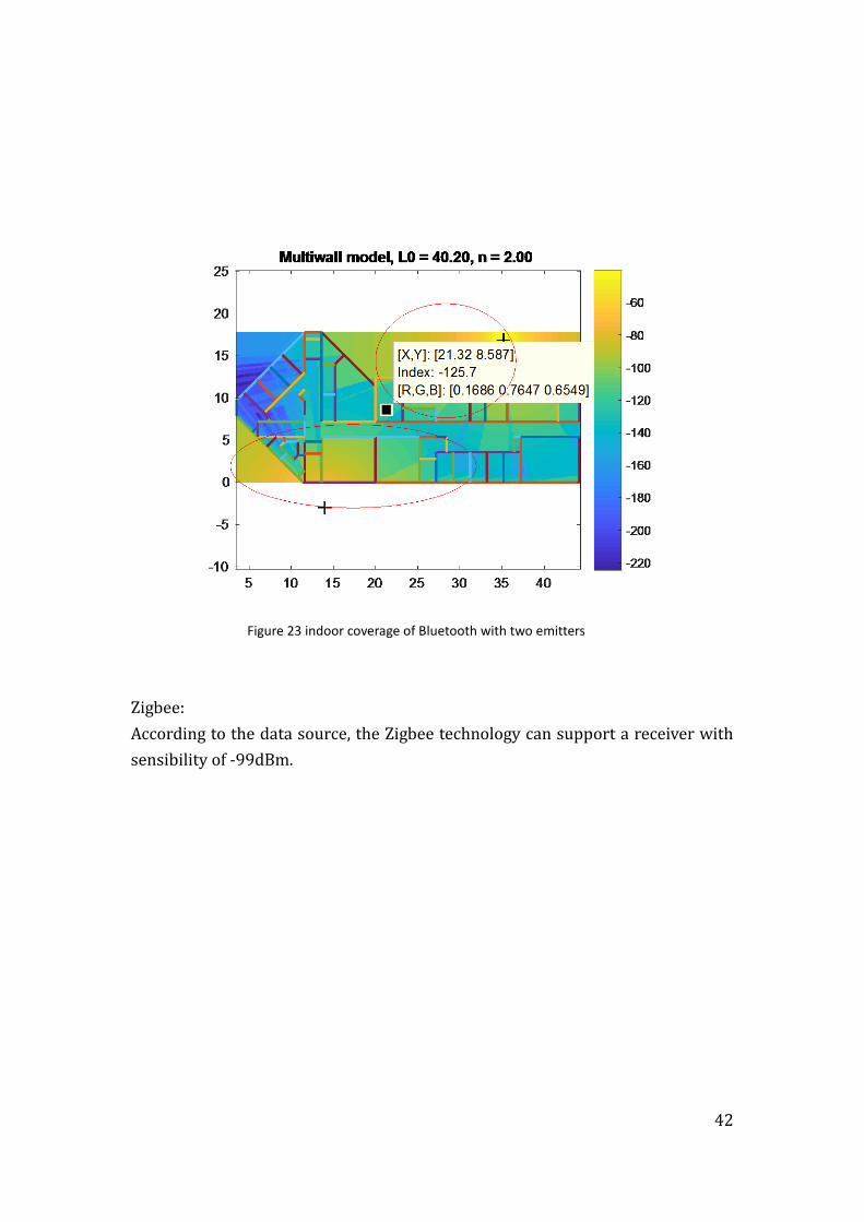
Figure 23 indoor coverage of Bluetooth with two emitters
Zigbee:
According to the data source, the Zigbee technology can support a receiver with
sensibility of -99dBm.
43
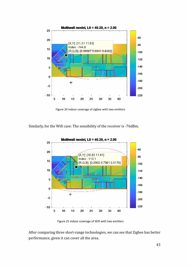
Figure 24 indoor coverage of zigbee with two emitters
Similarly, for the Wifi case: The sensibility of the receiver is -76dBm.
Figure 25 indoor coverage of Wifi with two emitters
After comparing three short-range technologies, we can see that Zigbee has better
performance, given it can cover all the area.
44
4. Latency study
The main influencing factors of radio network delay are divided into two
categories: one is the influence of dynamic spectrum resources, including the
activities of authorized users and the number of channels. The other is the
influence of node density, which is described in detail below.
(1) The impact of authorized user activities
In the cognitive radio network, the authorized user has the priority of spectrum
access, and the cognitive user can only choose the spectrum when the authorized
user is idle. When the authorized user appears, the cognitive user must let the
borrower's registration Channel, switching to other available channels. Frequent
spectral switching will result in a large switching delay. Therefore, the dynamic
change of spectrum caused by authorized user activity is an important reason for
the delay of cognitive radio network.
In the traditional wireless network, the distance between the nodes and the
transmission power are the key factors to determine the communication, the two
nodes as long as the distance can be transmitted within each other, you can
establish a two-way connection. However, cognitive radio network communication
The problem is different from the traditional wireless network, the cognitive users
are faced with differentiated and time-varying spectrum, different nodes can use
the available channels may not be the same; and the availability of the spectrum
with the authorized user's activities In a cognitive radio network, two cognitive
users are able to communicate only in both cases where they are within each
other's communication range and have at least one common available channel. , in
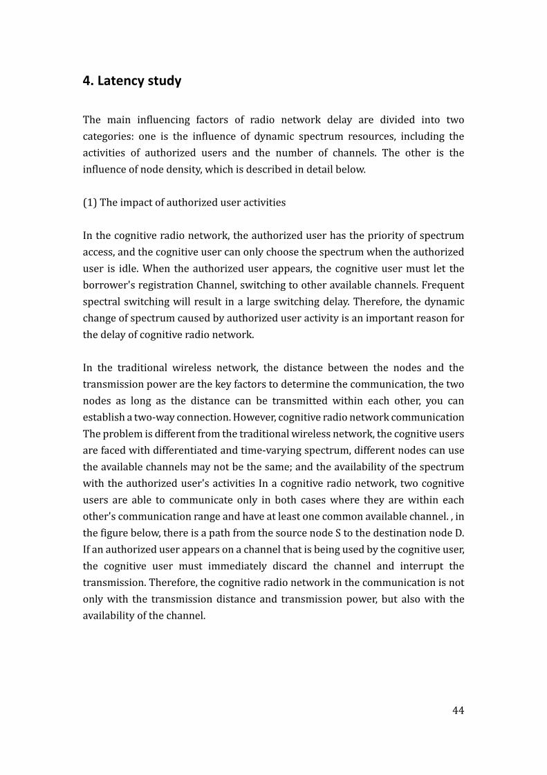
the figure below, there is a path from the source node S to the destination node D.
If an authorized user appears on a channel that is being used by the cognitive user,
the cognitive user must immediately discard the channel and interrupt the
transmission. Therefore, the cognitive radio network in the communication is not
only with the transmission distance and transmission power, but also with the
availability of the channel.
45
Figure 26 Impact of frequency dynamic characteristics on network
Considering this factor, as discussed before, the primary user against normal user
will be a reason of latency. In a technical way, it means that the unlicensed band
will have higher probability to occur the latency by users crashing.
For this reason, the following table shows the license issue of each technology:
xG Wifi zigbee bluetooth Lora sigfox Nb-IoT
Licensed Unlicensed Unlicensed Unlicensed Unlicensed Unlicensed licensed
Table 5 license comparison among Technologies
In conclusion of this part, the xG technologies and Nb-IoT will have better
performance in latency.
(2) The impact of the number of channels
The traditional wireless network adopts the fixed single channel spectrum access
mode, and the cognitive radio network adopts the more flexible spectrum access
mechanism, the user can use the channel of the whole channel. When the
number of channels is very small, the user can choose the opportunity. If the
available channel is not detected, the user will only interrupt the transmission
waiting for the available channel to increase the delay of the information
transmission, and vice versa, so the number of registered channels will also have
46
an impact on the network delay.
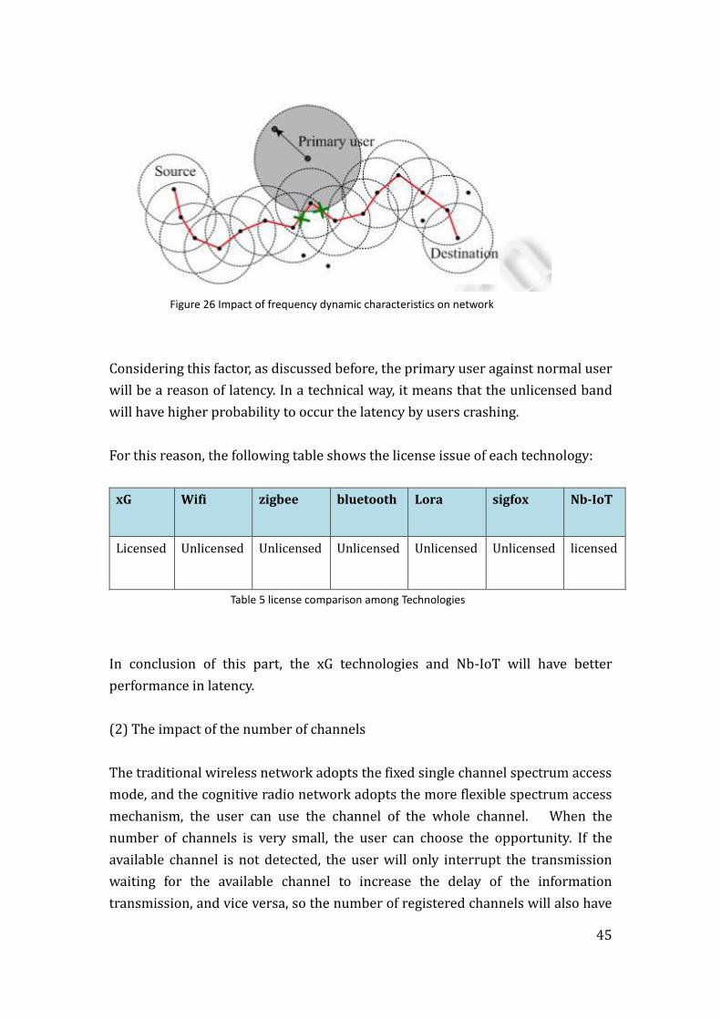
In general, the more channels, the lower the network latency, since the existence
of communication connections between two nodes depends on the available
frequency bands allocated to the geographic connection, then the delay of the
cognitive radio network depends on the current available spectrum.
Figure 27 cognitive radio graph model
Bluetooth:
Bluetooth uses frequency hopping (FHSS) technology with 79 channels and
1 MHz bandwidth.
Wifi:
Wi-Fi uses DSSS (802.11), complementary code keying (CCK, 802.1lb), or OFDM
modulation (802.11a/g) with 14 RF channels (11 available in US, 13 in Europe,
and just 1 in Japan) and 22 MHz bandwidth for each channel.
Zigbee:
Using direct sequence spread spectrum (DSSS) with16 channels and 2 MHz
bandwidth for each.
LoRa:
From 863 to 870 MHz, it has 8 channels with a separation of 0.3MHz. And from
902 to 928 MHz, there are 13 channels working properly with 2.16MHz of
47
separation.
Sigfox:
Using the band 868MHz to 868.6MHz with a bandwidth of 200Hz. 4 channels.
xG:
For 2G, it uses FDMA component splits the 890MHz to 915MHz band into 124
channels with a bandwidth of 200KHz.
For 3G, works on 1920 MHz to 1980 MHz and 2110 MHz - 2170 MHz (Frequency
Division Duplex). Maximum number of channels on 2x5MHz: 196 (spreading
factor 256 UL, AMR 7.95kbps) and 98 (spreading factor 128 UL, AMR 12.2kbps).
And for 4G, it can be up to 65540.
NB-IOT:
3 ways for the deployments. 1 channel only for each deployment.
In summary, as the table below we can see clearly that the xG and Bluetooth have
much more channels which means they could have less latency:
xG wifi zigbee bluetooth Lora Sigfox Nb-IoT
124,196,65540 14 16 79 21 4 1
Table 6 Comparison of number of channels
(3) The effect of node density
The density of the nodes in the cognitive radio network can be subdivided into the
authorized user density and the cognitive user density, which will have an impact
on the network delay. When the authorized user density is small, the area affected
by it is small and left to the cognitive user the frequency of the spectrum is
relatively large, the transmission delay of the cognitive user is small and inversely
proportional to the density of the cognitive user. When the node density of the
authorized user is large, the influence range is large and the chance of the
48
spectrum is small the extension of the extension; when the authorized user density
is large enough, no spectrum opportunities are available, the network delay will
approach infinity.
For example, in the process of routing design, Network transmission delay to
allocate the spectrum resources reasonably, in order to optimize the utilization of
spectrum resources; in the process of network topology control, according to the
network delay situation to dynamically adjust the node deployment, so as to
maximize the network coverage.

49
5. Geolocation
In the world of Drones, depending on the drones' performances and applications,
its need to be implemented the Geolocation function in order to obtain the location
such as in the scenario life searching and also it allows to associate images to
coordinates with great precision.
For tracking the device´s location, there are following methods existent:
GPS technology:
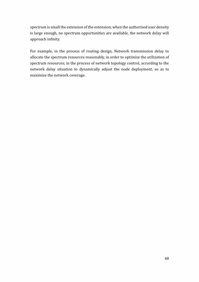
The basic principle of the GPS navigation system is to measure the distance
between the satellite of the known location and the user receiver, and then the data
of the multiple satellites can be used to know the specific location of the receiver.
To achieve this, the location of the satellite can be based on the time recorded on
the satellite clock in the satellite ephemeris to detect. And the distance from the
user to the satellite is recorded by the time the satellite signal is transmitted to the
user, and then multiplied by the speed of light as the following figures.
Figure 28 GPS principle 1
50
Figure 29 GPS calculation method
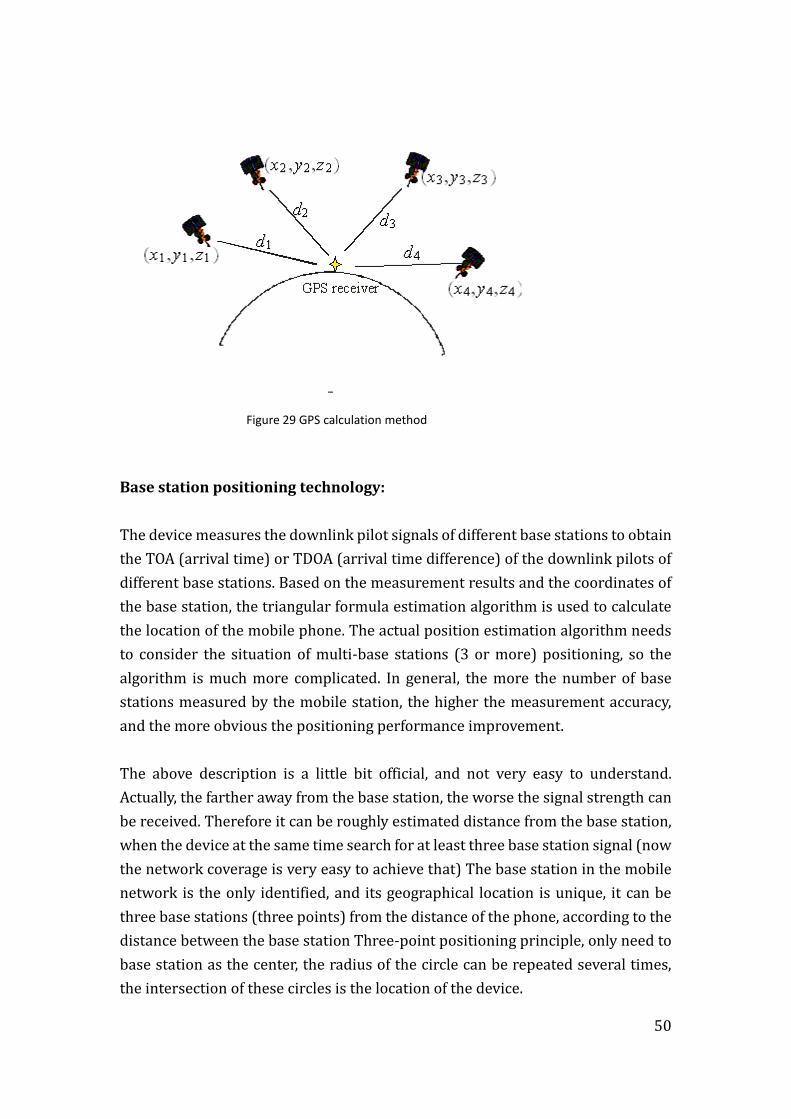
Base station positioning technology:
The device measures the downlink pilot signals of different base stations to obtain
the TOA (arrival time) or TDOA (arrival time difference) of the downlink pilots of
different base stations. Based on the measurement results and the coordinates of
the base station, the triangular formula estimation algorithm is used to calculate
the location of the mobile phone. The actual position estimation algorithm needs
to consider the situation of multi-base stations (3 or more) positioning, so the
algorithm is much more complicated. In general, the more the number of base
stations measured by the mobile station, the higher the measurement accuracy,
and the more obvious the positioning performance improvement.
The above description is a little bit official, and not very easy to understand.
Actually, the farther away from the base station, the worse the signal strength can
be received. Therefore it can be roughly estimated distance from the base station,
when the device at the same time search for at least three base station signal (now
the network coverage is very easy to achieve that) The base station in the mobile
network is the only identified, and its geographical location is unique, it can be
three base stations (three points) from the distance of the phone, according to the
distance between the base station Three-point positioning principle, only need to
base station as the center, the radius of the circle can be repeated several times,
the intersection of these circles is the location of the device.
51
Figure 30 Base station positioning
Wi-Fi positioning technology:
Wi-Fi positioning technology is usually used for commercial sites, such as
shopping malls, car parks and so on.
Using the Wi-Fi technology positioning, the use of received signal strength method
(RSSI), namely: distance from the AP, the received signal strength is weak; and
wireless AP position is relatively stable, and will not move. In this way, you can use
the device to collect the strength of the AP signal to determine its current location.
But the AP signal strength and resolution of the distance is not high, more
vulnerable to the impact of the crowd, the impact of environmental changes, while
the Wi-Fi 2.4G environment is more full of ZigBee, Bluetooth and other signals,
channel environment difference to determine Wi-Fi positioning accuracy Will not
exceed 3m, the current Wi-Fi positioning accuracy in the best environment can
reach 5 meters -10 meters level.
Bluetooth wireless positioning technology:
After Apple released iBeacon function, the use of Bluetooth wireless positioning
technology began to develop rapidly, positioning principle is very similar to Wi-

52
Fi positioning technology. Bluetooth positioning accuracy is slightly higher; but
because Bluetooth technology communication distance is short, it is not suitable
for large positioning the scene.
Another shortage of the Bluetooth positioning technology is requirement of pre-
installed. Generally through the deployment of these scenes in the Bluetooth
beacon (Beacon), as well as mobile phones and other equipment pre-installed
Bluetooth positioning APP, to achieve the positioning of the phone itself. As well as
Wi-Fi positioning, using the Bluetooth technology positioning, using the received
signal strength method (RSSI), that is, from the beacon distance, the received
signal strength is weak; and Bluetooth beacon position stability, will not move. So
you can use your phone and other devices to collect the intensity of the Bluetooth
beacon to determine its current location. But the Bluetooth beacon intensity and
resolution of the distance is not high, Wi-Fi signal is more susceptible to the crowd,
the environment and Bluetooth is also in the 2.4G band, the channel environment
is not very ideally. At present, the localization of Bluetooth positioning enterprises
in the best environment can reach the range of 3-8 meters.
ZigBee positioning is an industrial positioning technology, users need to set up
the first area in the ZigBee positioning base station, and then locate the device.
Like Wi-Fi and Bluetooth technology, ZigBee uses the received signal strength
method (RSSI) and is in the 2.4G band. ZigBee positioning accuracy is generally NO
more than 3 meters.
For the LPWA technologies, for instance Lora and sigfox, they have the similar
methods to track their devices but with their own base stations. The private
stations can avoid the inferences caused by other devices using other transmission
technologies, but due to the LOW power and LOW cost factor, they cannot
guarantee de accuracy of the location tracking. Normally it can only detect an area,
not a specific point like the following figure:

53
Figure 31 LPWA device tracking
In conclusion, the following table shows the tracking method applied in each
wireless technology and its accuracy.
GEOLOCATION METHOD ACCURACY
WIFI WIFI POSITIONING (RSSI) 5-10 METERS
BLUETOOTH BLUETOOTH (RSSI) 3-8 METERS
ZIGBEE RSSI <3METERS
NB_IOT BOTH GPS OR BASE STATION 0-100METERS(with GPS
can have low to 10m)
LORA BASE STATION 10 STATIC 35 DINAMIC
SIGFOX RSSI probability calculation 500 METERS
LTE BASE STATION OR GPS 10 METERS
Table 7 Geolocation summary
54
6. Deployment of the drone´s Wireless systems
After all the analysis of the main factors influencing the performance of wireless
systems, we can notice that there is no technology which shows all the parameters
and performance excellent. Each one has its own strengths and weaknesses. When
we design a concrete system for a concrete utility, we should compare all the
characteristics at same time to be able to take a decision.
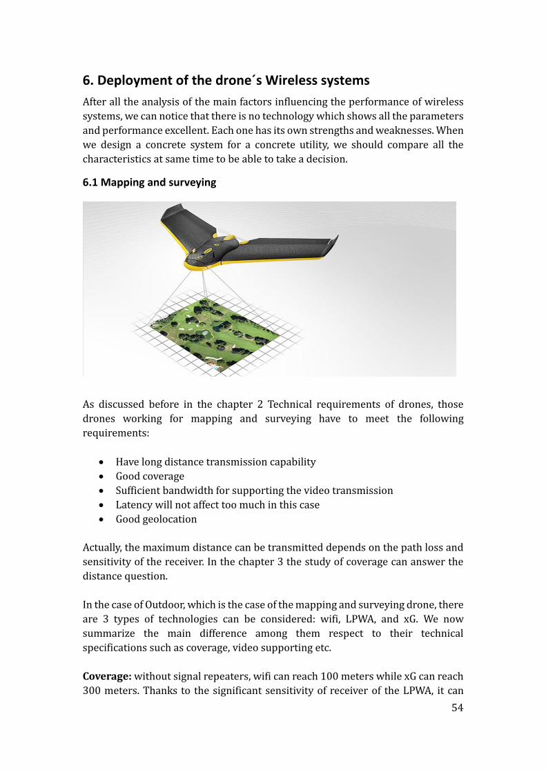
6.1 Mapping and surveying
As discussed before in the chapter 2 Technical requirements of drones, those
drones working for mapping and surveying have to meet the following
requirements:
Have long distance transmission capability
Good coverage
Sufficient bandwidth for supporting the video transmission
Latency will not affect too much in this case
Good geolocation
Actually, the maximum distance can be transmitted depends on the path loss and
sensitivity of the receiver. In the chapter 3 the study of coverage can answer the
distance question.
In the case of Outdoor, which is the case of the mapping and surveying drone, there
are 3 types of technologies can be considered: wifi, LPWA, and xG. We now
summarize the main difference among them respect to their technical
specifications such as coverage, video supporting etc.
Coverage: without signal repeaters, wifi can reach 100 meters while xG can reach
300 meters. Thanks to the significant sensitivity of receiver of the LPWA, it can
55
cover more than 30km.
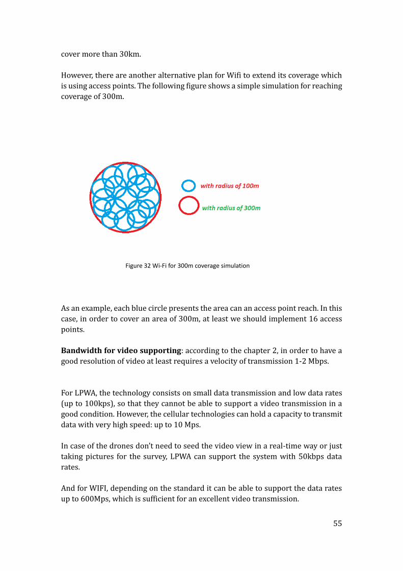
However, there are another alternative plan for Wifi to extend its coverage which
is using access points. The following figure shows a simple simulation for reaching
coverage of 300m.
Figure 32 Wi-Fi for 300m coverage simulation
As an example, each blue circle presents the area can an access point reach. In this
case, in order to cover an area of 300m, at least we should implement 16 access
points.
Bandwidth for video supporting: according to the chapter 2, in order to have a
good resolution of video at least requires a velocity of transmission 1-2 Mbps.
For LPWA, the technology consists on small data transmission and low data rates
(up to 100kps), so that they cannot be able to support a video transmission in a
good condition. However, the cellular technologies can hold a capacity to transmit
data with very high speed: up to 10 Mps.
In case of the drones don’t need to seed the video view in a real-time way or just
taking pictures for the survey, LPWA can support the system with 50kbps data
rates.
And for WIFI, depending on the standard it can be able to support the data rates
up to 600Mps, which is sufficient for an excellent video transmission.
56
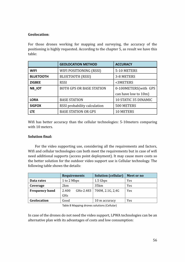
Geolocation:
For those drones working for mapping and surveying, the accuracy of the
positioning is highly requested. According to the chapter 5, as result we have this
table:
GEOLOCATION METHOD ACCURACY
WIFI WIFI POSITIONING (RSSI) 5-10 METERS
BLUETOOTH BLUETOOTH (RSSI) 3-8 METERS
ZIGBEE RSSI <3METERS
NB_IOT BOTH GPS OR BASE STATION 0-100METERS(with GPS
can have low to 10m)
LORA BASE STATION 10 STATIC 35 DINAMIC
SIGFOX RSSI probability calculation 500 METERS
LTE BASE STATION OR GPS 10 METERS
Wifi has better accuracy than the cellular technologies: 5-10meters comparing
with 10 meters.
Solution final:
For the video supporting use, considering all the requirements and factors,
Wifi and cellular technologies can both meet the requirements but in case of wifi
need additional supports (access point deployment). It may cause more costs so
the better solution for the outdoor video support use is Cellular technology. The
following table shows the details:
Requirements Solution (cellular) Meet or no
Data rates 1 to 2 Mbps 1.5 Gbps Yes
Coverage 2km 35km Yes
Frequency band 2.400 GHz-2.483
GHz
700M, 2.1G, 2,4G Yes
Geolocation Good 10 m accuracy Yes
Table 8 Mapping drones solutions (Cellular)
In case of the drones do not need the video support, LPWA technologies can be an
alternative plan with its advantages of costs and low consumption:
57
Requirements Solution (nb-IoT) Meet or no
Data rates 50kbps 50kbps Yes
Coverage 2km 40km Yes
Frequency band 2.400 GHz-2.483
GHz
2.4G Yes
Geolocation Good 10 m accuracy in
case of using GPS
Yes
Table 9 Mapping drones solutions (NB-IoT)
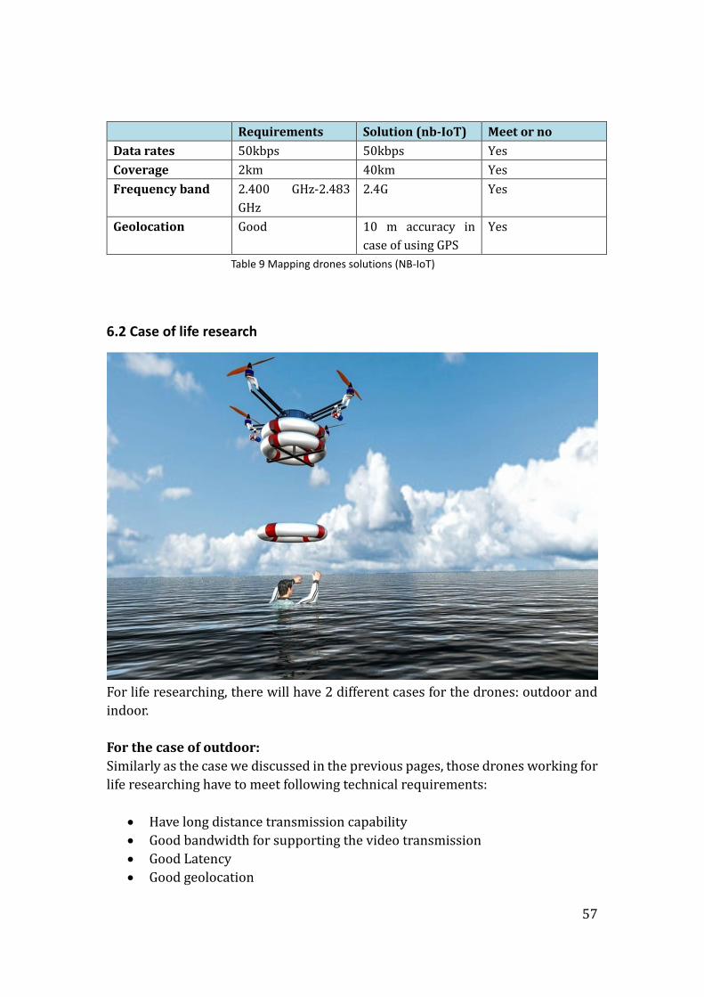
6.2 Case of life research
For life researching, there will have 2 different cases for the drones: outdoor and
indoor.
For the case of outdoor:
Similarly as the case we discussed in the previous pages, those drones working for
life researching have to meet following technical requirements:
Have long distance transmission capability
Good bandwidth for supporting the video transmission
Good Latency
Good geolocation
58
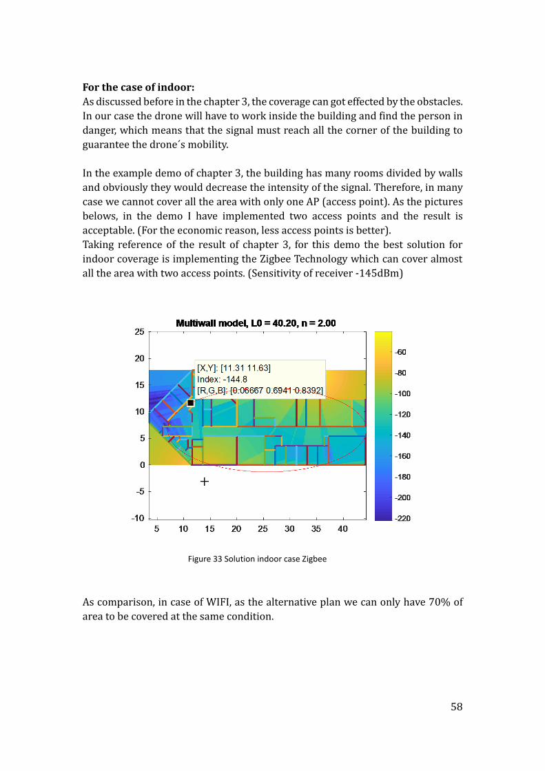
For the case of indoor:
As discussed before in the chapter 3, the coverage can got effected by the obstacles.
In our case the drone will have to work inside the building and find the person in
danger, which means that the signal must reach all the corner of the building to
guarantee the drone´s mobility.
In the example demo of chapter 3, the building has many rooms divided by walls
and obviously they would decrease the intensity of the signal. Therefore, in many
case we cannot cover all the area with only one AP (access point). As the pictures
belows, in the demo I have implemented two access points and the result is
acceptable. (For the economic reason, less access points is better).
Taking reference of the result of chapter 3, for this demo the best solution for
indoor coverage is implementing the Zigbee Technology which can cover almost
all the area with two access points. (Sensitivity of receiver -145dBm)
Figure 33 Solution indoor case Zigbee
As comparison, in case of WIFI, as the alternative plan we can only have 70% of
area to be covered at the same condition.
59
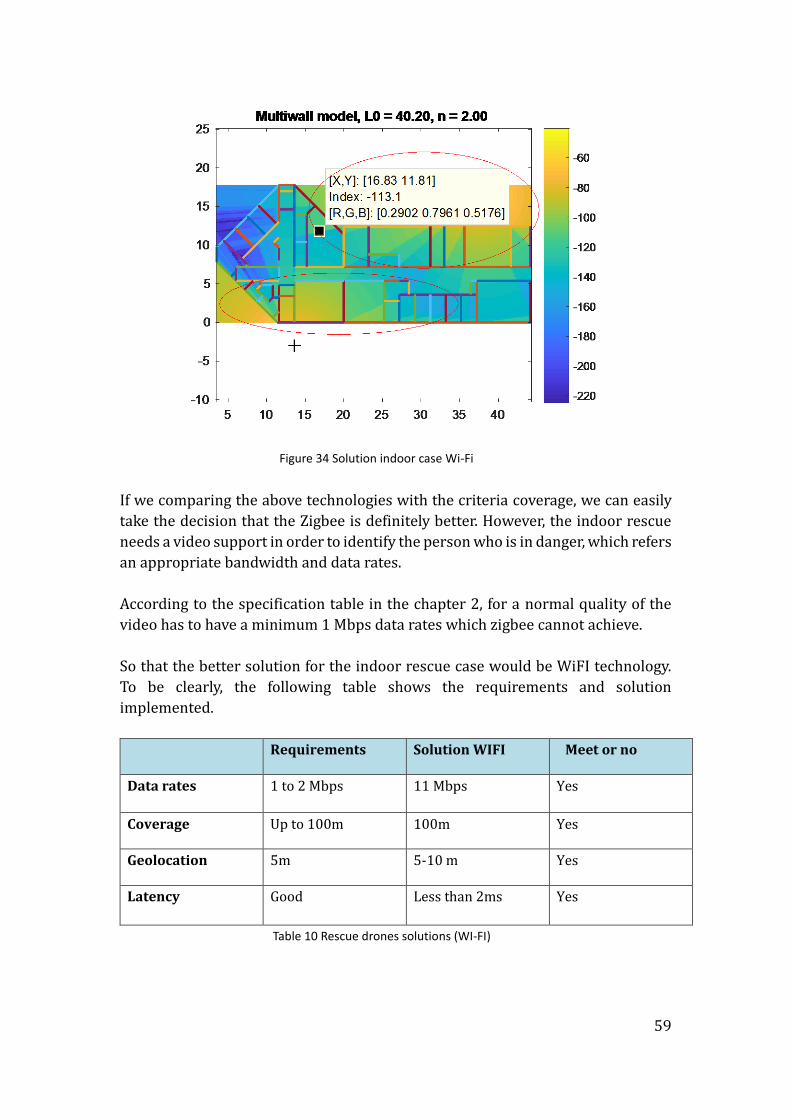
Figure 34 Solution indoor case Wi-Fi
If we comparing the above technologies with the criteria coverage, we can easily
take the decision that the Zigbee is definitely better. However, the indoor rescue
needs a video support in order to identify the person who is in danger, which refers
an appropriate bandwidth and data rates.
According to the specification table in the chapter 2, for a normal quality of the
video has to have a minimum 1 Mbps data rates which zigbee cannot achieve.
So that the better solution for the indoor rescue case would be WiFI technology.
To be clearly, the following table shows the requirements and solution
implemented.
Requirements Solution WIFI Meet or no
Data rates 1 to 2 Mbps 11 Mbps Yes
Coverage Up to 100m 100m Yes
Geolocation 5m 5-10 m Yes
Latency Good Less than 2ms Yes
Table 10 Rescue drones solutions (WI-FI)
60
6.3 Case of leisure
In order to enable the FPV ( first person view), there are some requirements that
should meet:
Have long distance transmission capability
Good coverage
Sufficient bandwidth for supporting the video transmission
Latency will be the most important factor
Good geolocation
In the chapter 4 we have discussed the latency issue, as a result, the cellular
technologies and WiFi can have better performance related to the latency.
Moreover, both technologies can support a very good resolution of video thanks to
the bandwidth capability.
However, WIFI has a shortage which is the coverage comparing with cellular
technologies. So the solution for the FPV drones will be depended on the flying
range. If the user don’t need to fly further (more than 100m), wifi will be the better
choice. Otherwise it can only be Cellular technologies because the LPWA t cannot
support video transmission and for the single user will be not able to implement
access points to extend the coverage.
Solution for drones flying no more than 100m:
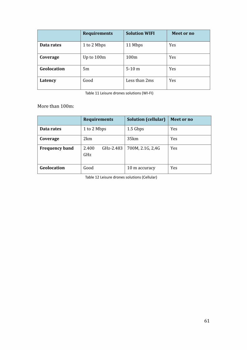
61
Requirements Solution WIFI Meet or no
Data rates 1 to 2 Mbps 11 Mbps Yes
Coverage Up to 100m 100m Yes
Geolocation 5m 5-10 m Yes
Latency Good Less than 2ms Yes
Table 11 Leisure drones solutions (WI-FI)
More than 100m:
Requirements Solution (cellular) Meet or no
Data rates 1 to 2 Mbps 1.5 Gbps Yes
Coverage 2km 35km Yes
Frequency band 2.400 GHz-2.483
GHz
700M, 2.1G, 2,4G Yes
Geolocation Good 10 m accuracy Yes
Table 12 Leisure drones solutions (Cellular)
62
6. Budget
In this chapter, I am going to reflect the expenses derived from carrying out this
final project. However, we will not be able to quantify the materials that have been
used in different chapters as references because they belong to the Universidad
Politécnica de Madrid.
The budget will be divided into two parts. On the one hand we will have the cost
of different tools, software that have been used throughout the project and on the
other, we will have the costs associated with the number of hours invested in
developing it.
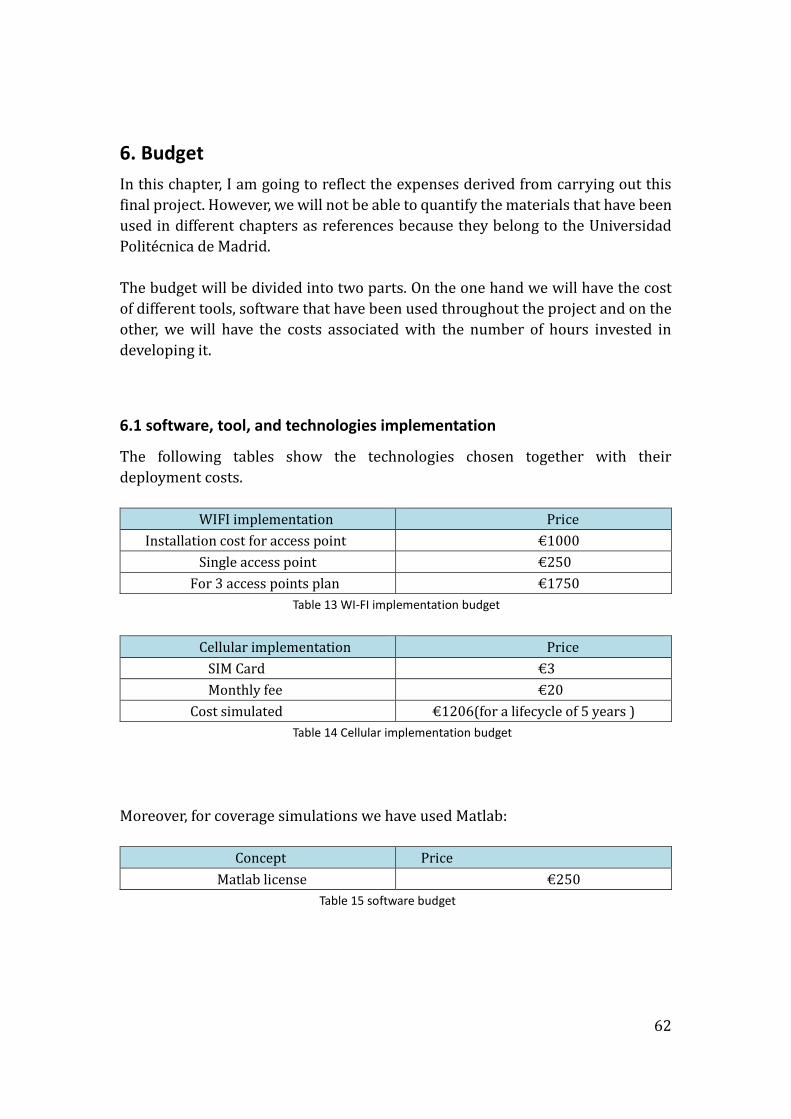
6.1 software, tool, and technologies implementation
The following tables show the technologies chosen together with their
deployment costs.
WIFI implementation Price
Installation cost for access point €1000
Single access point €250
For 3 access points plan €1750
Table 13 WI-FI implementation budget
Cellular implementation Price
SIM Card €3
Monthly fee €20
Cost simulated €1206(for a lifecycle of 5 years )
Table 14 Cellular implementation budget
Moreover, for coverage simulations we have used Matlab:
Concept Price
Matlab license €250
Table 15 software budget

63
6.2 labor costs and invested hours
For this section, according to the document "Rates 2015 for taxable parcels" made
by the TRAGSA group, the price per hour for a superior degree without experience,
is 22 € / h. the following table shows the budget derived from labor costs.
Concept Hours Price
Previous study 25 €550
Design and Simulation 120 €2640
Analysis 80 €960
Writing 80 €960
Helping from my
supervisor
40 €1200
Table 16 Labor costs and invested hours
64
7. Conclusion
In this paper, through the system of wireless communication technology research,
three different functional use of UAV´s wireless communication have been
designed appropriately: for mapping and surveying drones the best choice is
Celluar system or LPWA depending the video condition; for rescue drones Wifi
system can be implemented; and for the leisure case, depending on the flying
distance, the system can vary from Wifi to Cellular.
For designing a technical system we should consider if the design suit for the use
or not. For instance, the drone´s need of the service of video support is directly
related with the bandwidth requirement and the need of the real-time
communication requirement can effect a lot in the area of latency and geolocation.
By analyzing and simulating different parameters of different wireless
technologies and compared its advantages and disadvantages, also with the
different UAV´s requirements, the final design could meet those requirements of
each UAV functionality.
More in detail, in the stage of coverage simulation especially in the case of indoor,
zigbee was the best choice and for outdoor, the LPWA also have very good
performance. But for a complete wireless system design it does not depend on only
one or two factors. It also happens when we began with latency study, geolocation
factors study.
In conclusion we have selected cellular technology for the Mapping and surveying
function due to its good coverage and the video support capacity. And for both life
rescue function and leisure, the Wifi was the better choice considering of the
latency factor and bandwidth.
Finally, I would like to mention that personally the realization of this project has
been a real challenge for me, since it has allowed me to acquire a greater
specialization in knowledge obtained in the university and also to learn and
contemplate other visions, not exclusively technical, that are required in the
realization Of any project and which, like the technological section, are also very
important. And I was very lucky to introduce my knowledge of this project into my
daily work at Telefonica.
65
8. Biography and references
[1] Thethingsnetwork.org. (2017). The Things Network. [online] Available
at: https://www.thethingsnetwork.org/wiki/LoRaWAN/Home.
[Accessed 25 May. 2017].
[2] Anon, (2017). [online] Available at:
http://internetofthingsagenda.techtarget.com/definition/ZigBee.
[Accessed 5 May. 2017].
[3] Anon, (2017). [online] Available at:
https://elandroidelibre.elespanol.com/2015/08/todo-sobre-zigbee-la-
tecnologia-ultrabarata-para-comunicacion-inalambrica.html. [Accessed
4 Apr. 2017].
[4] DroneZon. (2017). Introduction To UAV Photogrammetry And Lidar
Mapping Basics. [online] Available at:
https://www.dronezon.com/learn-about-drones-
quadcopters/introduction-to-uav-photogrammetry-and-lidar-mapping-
basics/ [Accessed 3 May 2017].
[5] Wiki.dji.com. (2017). Phantom 3 Professional - DJI Wiki. [online]
Available at:
http://wiki.dji.com/en/index.php/Phantom_3_Professional [Accessed 5
Jun. 2017].
[6] Anon, (2017). [online] Available at: [En línea]. Available:
https://www.dji.com/mavic/info [Accessed 5 Jun. 2017].
[7] Mail Online. (2017). Beach lifeguards could be replaced by drones. [online]
Available at: http://www.dailymail.co.uk/travel/travel_news/article-
2980876/Not-patch-Pammie-Beach-lifeguards-soon-replaced-robots-
inventor-creates-life-saving-drones.html [Accessed 5 Apr. 2017].
[8] DJI Official. (2017). DJI - The World Leader in Camera
Drones/Quadcopters for Aerial Photography. [online] Available at:
http://www.dji.com/dji-goggles/info#specs [Accessed 5 Apr. 2017].
[9] DroneTrest. (2017). FPV Cameras for your drone - what you need to know
before you buy one. [online] Available at:
http://www.dronetrest.com/t/fpv-cameras-for-your-drone-what-you-
need-to-know-before-you-buy-one/1441 [Accessed 5 Apr. 2017].
[10] [Hh.se. (2017). Cite a Website - Cite This For Me. [online] Available at:
http://www.hh.se/download/18.70cf2e49129168da015800094781/1
341267715838/7_6_Jitter.pdf. [Accessed 5 Jun. 2017].
[11] Anon, (2017). [online] Available at:
66
http://www.technolec.be/images/files/Application_Guidebook-Video-
over-Wireless_Networks.pdf.
[12] A. A.-Z. SIMON R. SAUNDERS, Antennas and propagation for wireless
communication systems, second edition, 1999.
[13] DJI Official. (2017). DJI - The World Leader in Camera
Drones/Quadcopters for Aerial Photography. [online] Available at:
http://www.dji.com/dji-goggles/info#specs [Accessed 5 Jun. 2017].