Embed Size (px)
Citation preview
PROJECT:
CHINA DEVELOPMENT BANK FUNDED PRIORITY ROAD
PROJECT-3(PRP3-PHASE II)
REHABILITATION/IMPROVEMENTS OF THIBBUTTA
JUNCTION FROM DEMALARAWA-PANANETIPOLA-
BATTAGALLA ROAD
FROM CH 0+000 TO CH 5+000 KM
2016 OCTOBER
`
DETAILED ENGINEERING DESIGNS PAVEMENT DESIGN REPORT
THIBBUTTA JUNCTION FROM DEMALARAWA-PANANETIPOLA-BATTAGALLA ROAD
FROM CH 0+000-3+219 FROM CH 07+000 TO CH 09+400 KM
CLIENT & ENGINEER
DESIGN
SUB-CONTRACTOR
CONTRACTOR
1
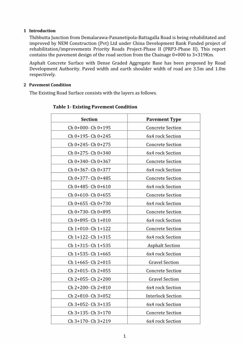
1 Introduction
Thibbutta Junction from Demalarawa-Pananetipola-Battagalla Road is being rehabilitated and improved by NEM Construction (Pvt) Ltd under China Development Bank Funded project of rehabilitation/improvements Priority Roads Project-Phase II (PRP3-Phase II). This report contains the pavement design of the road section from the Chainage 0+000 to 3+319Km.
Asphalt Concrete Surface with Dense Graded Aggregate Base has been proposed by Road Development Authority. Paved width and earth shoulder width of road are 3.5m and 1.0m respectively.
2 Pavement Condition
The Existing Road Surface consists with the layers as follows.
Table 1- Existing Pavement Condition
Section Pavement Type
Ch 0+000- Ch 0+195 Concrete Section
Ch 0+195- Ch 0+245 6x4 rock Section
Ch 0+245- Ch 0+275 Concrete Section
Ch 0+275- Ch 0+340 6x4 rock Section
Ch 0+340- Ch 0+367 Concrete Section
Ch 0+367- Ch 0+377 6x4 rock Section
Ch 0+377- Ch 0+485 Concrete Section
Ch 0+485- Ch 0+610 6x4 rock Section
Ch 0+610- Ch 0+655 Concrete Section
Ch 0+655 -Ch 0+730 6x4 rock Section
Ch 0+730- Ch 0+895 Concrete Section
Ch 0+895- Ch 1+010 6x4 rock Section
Ch 1+010- Ch 1+122 Concrete Section
Ch 1+122- Ch 1+315 6x4 rock Section
Ch 1+315- Ch 1+535 Asphalt Section
Ch 1+535- Ch 1+665 6x4 rock Section
Ch 1+665- Ch 2+015 Gravel Section
Ch 2+015- Ch 2+055 Concrete Section
Ch 2+055- Ch 2+200 Gravel Section
Ch 2+200- Ch 2+810 6x4 rock Section
Ch 2+810- Ch 3+052 Interlock Section
Ch 3+052- Ch 3+135 6x4 rock Section
Ch 3+135- Ch 3+170 Concrete Section
Ch 3+170- Ch 3+219 6x4 rock Section
2
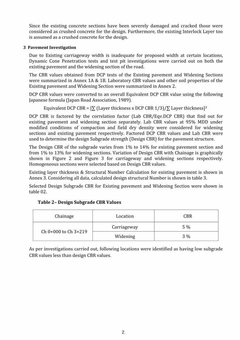
Since the existing concrete sections have been severely damaged and cracked those were considered as crushed concrete for the design. Furthermore, the existing Interlock Layer too is assumed as a crushed concrete for the design.
3 Pavement Investigation
Due to Existing carriageway width is inadequate for proposed width at certain locations, Dynamic Cone Penetration tests and test pit investigations were carried out on both the existing pavement and the widening section of the road.
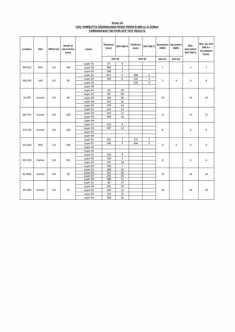
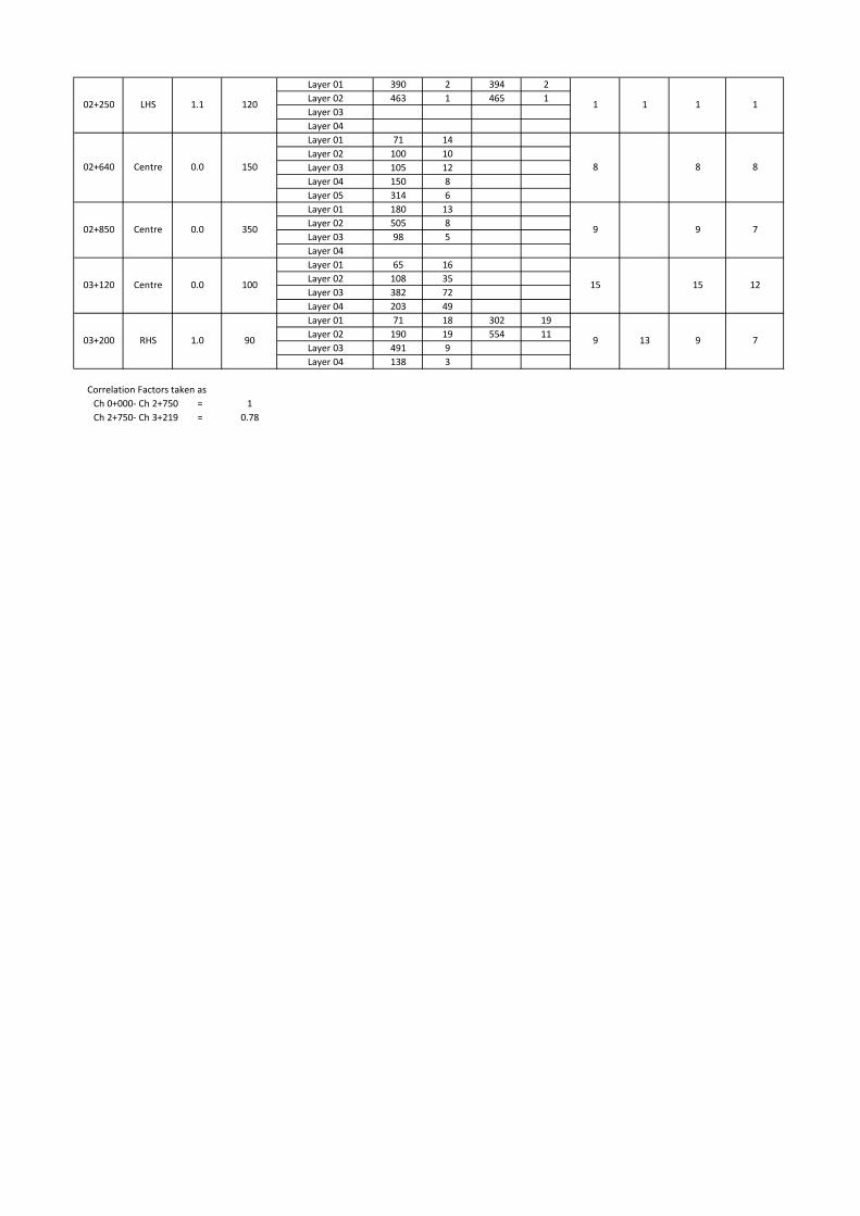
The CBR values obtained from DCP tests of the Existing pavement and Widening Sections were summarized in Annex 1A & 1B. Laboratory CBR values and other soil properties of the Existing pavement and Widening Section were summarized in Annex 2.
DCP CBR values were converted to an overall Equivalent DCP CBR value using the following Japanese formula (Japan Road Association, 1989).
Equivalent DCP CBR = [∑ (Layer thickness x DCP CBR 1/3)/∑ Layer thickness]3
DCP CBR is factored by the correlation factor (Lab CBR/Eqv.DCP CBR) that find out for existing pavement and widening section separately. Lab CBR values at 95% MDD under modified conditions of compaction and field dry density were considered for widening sections and existing pavement respectively. Factored DCP CBR values and Lab CBR were used to determine the design Subgrade strength (Design CBR) for the pavement structure.
The Design CBR of the subgrade varies from 1% to 14% for existing pavement section and from 1% to 13% for widening sections. Variation of Design CBR with Chainage is graphically shown in Figure 2 and Figure 3 for carriageway and widening sections respectively. Homogeneous sections were selected based on Design CBR values.
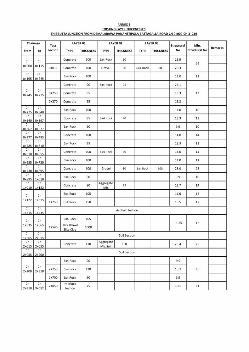
Existing layer thickness & Structural Number Calculation for existing pavement is shown in Annex 3. Considering all data, calculated design structural Number is shown in table 3.
Selected Design Subgrade CBR for Existing pavement and Widening Section were shown in table 02.
Table 2– Design Subgrade CBR Values
As per investigations carried out, following locations were identified as having low subgrade
CBR values less than design CBR values.
Chainage Location CBR
Ch 0+000 to Ch 3+219 Carriageway 5 %
Widening 3 %
3
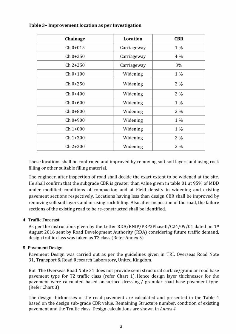
Table 3– Improvement location as per Investigation
These locations shall be confirmed and improved by removing soft soil layers and using rock
filling or other suitable filling material.
The engineer, after inspection of road shall decide the exact extent to be widened at the site.
He shall confirm that the subgrade CBR is greater than value given in table 01 at 95% of MDD
under modified conditions of compaction and at Field density in widening and existing
pavement sections respectively. Locations having less than design CBR shall be improved by
removing soft soil layers and or using rock filling. Also after inspection of the road, the failure
sections of the existing road to be re-constructed shall be identified.
4 Traffic Forecast
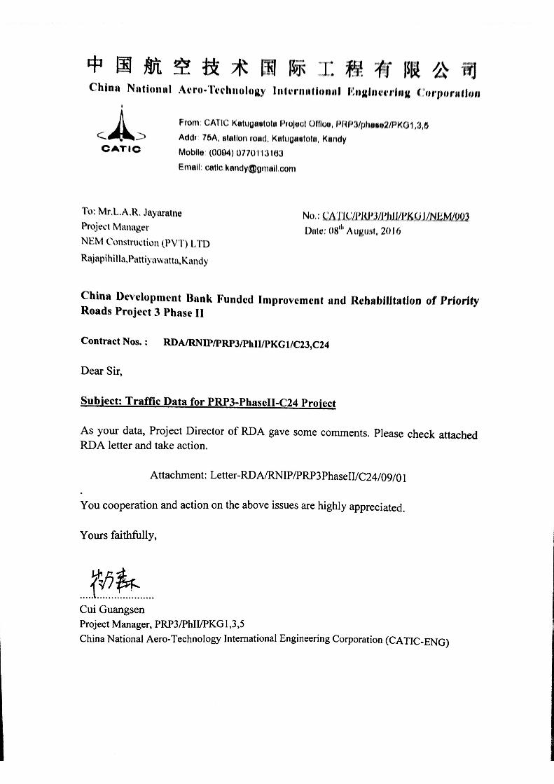
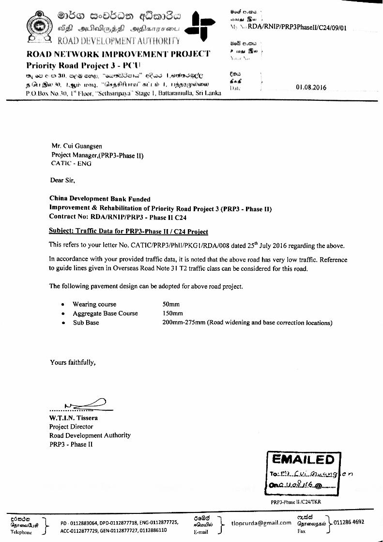
As per the instructions given by the Letter RDA/RNIP/PRP3PhaseII/C24/09/01 dated on 1st August 2016 sent by Road Development Authority (RDA) considering future traffic demand, design traffic class was taken as T2 class (Refer Annex 5)
5 Pavement Design
Pavement Design was carried out as per the guidelines given in TRL Overseas Road Note 31, Transport & Road Research Laboratory, United Kingdom.
But The Overseas Road Note 31 does not provide semi structural surface/granular road base pavement type for T2 traffic class (refer Chart 1). Hence design layer thicknesses for the pavement were calculated based on surface dressing / granular road base pavement type. (Refer Chart 3)
The design thicknesses of the road pavement are calculated and presented in the Table 4 based on the design sub-grade CBR value, Remaining Structure number, condition of existing pavement and the Traffic class. Design calculations are shown in Annex 4.
Chainage Location CBR
Ch 0+015 Carriageway 1 %
Ch 0+250 Carriageway 4 %
Ch 2+250 Carriageway 3%
Ch 0+100 Widening 1 %
Ch 0+250 Widening 2 %
Ch 0+400 Widening 2 %
Ch 0+600 Widening 1 %
Ch 0+800 Widening 2 %
Ch 0+900 Widening 1 %
Ch 1+000 Widening 1 %
Ch 1+300 Widening 2 %
Ch 2+200 Widening 2 %
4
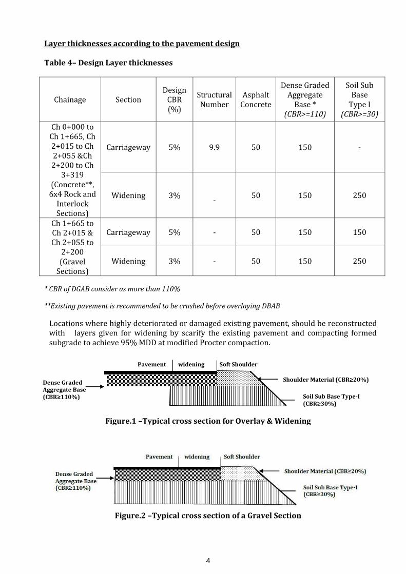
Layer thicknesses according to the pavement design
Table 4– Design Layer thicknesses
Chainage Section Design
CBR (%)
Structural Number
Asphalt Concrete
Dense Graded Aggregate
Base * (CBR>=110)
Soil Sub Base
Type I (CBR>=30)
Ch 0+000 to Ch 1+665, Ch 2+015 to Ch 2+055 &Ch 2+200 to Ch
3+319 (Concrete**,
6x4 Rock and Interlock Sections)
Carriageway 5% 9.9 50 150 -
Widening 3% -
50 150 250
Ch 1+665 to Ch 2+015 & Ch 2+055 to
2+200 (Gravel
Sections)
Carriageway 5% - 50 150 150
Widening 3% - 50 150 250
* CBR of DGAB consider as more than 110%
**Existing pavement is recommended to be crushed before overlaying DBAB
Locations where highly deteriorated or damaged existing pavement, should be reconstructed with layers given for widening by scarify the existing pavement and compacting formed subgrade to achieve 95% MDD at modified Procter compaction.
Pavement widening Soft Shoulder
Figure.1 –Typical cross section for Overlay & Widening
Figure.2 –Typical cross section of a Gravel Section
Shoulder Material (CBR≥20%)
Soil Sub Base Type-I (CBR≥30%)
Dense Graded Aggregate Base (CBR≥110%)
5
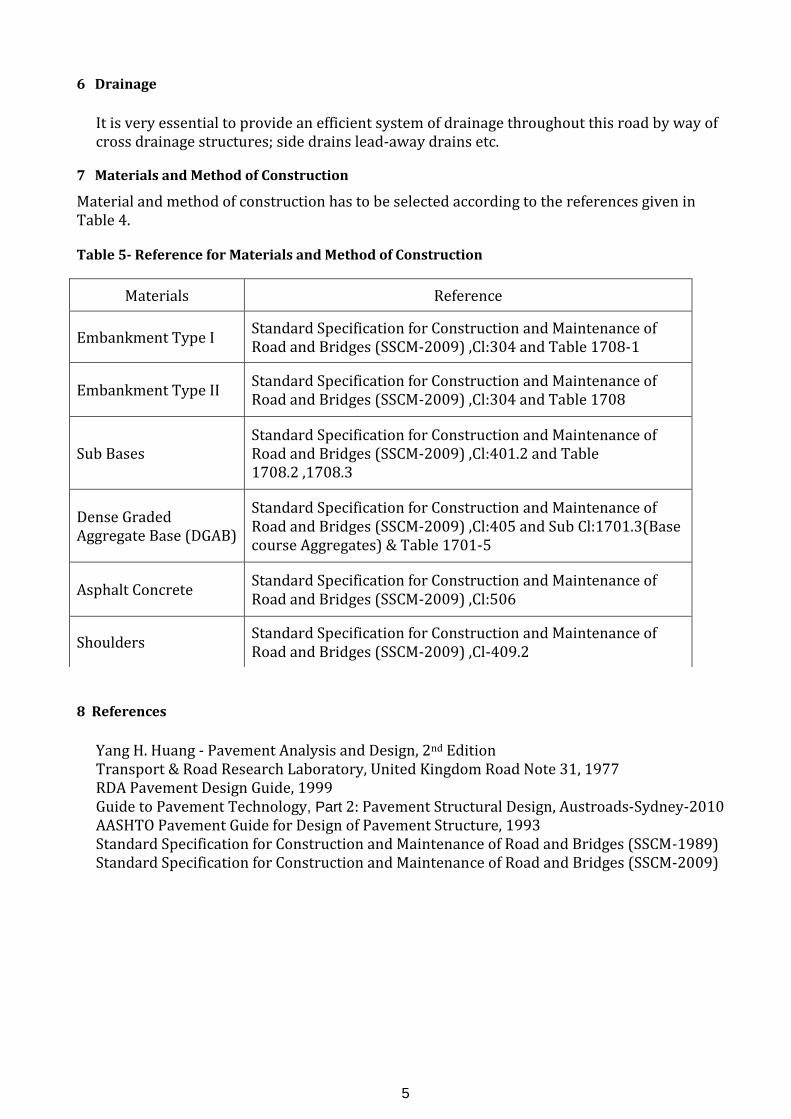
6 Drainage
It is very essential to provide an efficient system of drainage throughout this road by way of cross drainage structures; side drains lead-away drains etc.
7 Materials and Method of Construction
Material and method of construction has to be selected according to the references given in Table 4.
Table 5- Reference for Materials and Method of Construction
8 References
Yang H. Huang - Pavement Analysis and Design, 2nd Edition Transport & Road Research Laboratory, United Kingdom Road Note 31, 1977 RDA Pavement Design Guide, 1999 Guide to Pavement Technology, Part 2: Pavement Structural Design, Austroads-Sydney-2010 AASHTO Pavement Guide for Design of Pavement Structure, 1993 Standard Specification for Construction and Maintenance of Road and Bridges (SSCM-1989) Standard Specification for Construction and Maintenance of Road and Bridges (SSCM-2009)
Materials Reference
Embankment Type I Standard Specification for Construction and Maintenance of Road and Bridges (SSCM-2009) ,Cl:304 and Table 1708-1
Embankment Type II Standard Specification for Construction and Maintenance of Road and Bridges (SSCM-2009) ,Cl:304 and Table 1708
Sub Bases Standard Specification for Construction and Maintenance of Road and Bridges (SSCM-2009) ,Cl:401.2 and Table 1708.2 ,1708.3
Dense Graded Aggregate Base (DGAB)
Standard Specification for Construction and Maintenance of Road and Bridges (SSCM-2009) ,Cl:405 and Sub Cl:1701.3(Base course Aggregates) & Table 1701-5
Asphalt Concrete Standard Specification for Construction and Maintenance of Road and Bridges (SSCM-2009) ,Cl:506
Shoulders Standard Specification for Construction and Maintenance of Road and Bridges (SSCM-2009) ,Cl-409.2
Confirmation of Report Preparation
Prepared by,
…………………………………………
Eng. Prasan Premathilaka
Checked by,
…………………………………………
Eng. W.W. Bandara

Annex
DCP-01 DCP-02
Layer 01 67 4
Layer 02 498 1
Layer 03 290 2
Layer 01 612 5 388 6
Layer 02 230 8 232 3
Layer 03 234 9
Layer 04
Layer 01 43 18
Layer 02 83 64
Layer 03 144 40
Layer 04 216 16
Layer 05 378 14
Layer 01 219 13
Layer 02 223 11
Layer 03 338 10
Layer 04
Layer 01 310 6
Layer 02 397 12
Layer 03
Layer 04
Layer 01 332 7 375 7
Layer 02 536 3 459 3
Layer 03
Layer 04
Layer 01 218 8
Layer 02 150 5
Layer 03 147 10
Layer 04 246 7Layer 01 180 22Layer 02 167 39Layer 03 233 18Layer 04 288 11Layer 01 60 17
Layer 02 255 10
Layer 03 140 15
Layer 04 210 21
Layer 05 230 10
Location
10
Centre 0.0 120
02+185
0.0
01+250 RHS 1.0 150
6
4 4
601+550 Centre
Centre
10
6
4
14
Min. Eq. DCP
CBR % x
Correlation
Factor
6
14
125 6
Layers
Depth at
start of test
(mm)
Offset (m)Side
C24; THIBBUTTA DEBARALAWA ROAD FROM 0+000 to 3+319km
Annex 1A
CARRIAGEWAY SECTION DCP TEST RESULTS
11
00+015 RHS 0.2 100 1
Thickness
(mm)DCP CBR %
00+250 LHS 0.5 95 4
DCP CBR %
0+270 Centre 0.0 95
00+715
01+850
Centre 0.0 15 10
Centre 0.0 20 14
0.0 220
14
11
01+130
14
Thickness
(mm)
DCP-01 DCP-02
1
4
4
Min.
Equivalent
DCP CBR %
1
5 4
14
11
6
Equivalent
CBR%
Equivalent
CBR%
Layer 01 390 2 394 2
Layer 02 463 1 465 1
Layer 03
Layer 04
Layer 01 71 14
Layer 02 100 10
Layer 03 105 12
Layer 04 150 8
Layer 05 314 6
Layer 01 180 13
Layer 02 505 8
Layer 03 98 5
Layer 04
Layer 01 65 16
Layer 02 108 35
Layer 03 382 72
Layer 04 203 49
Layer 01 71 18 302 19
Layer 02 190 19 554 11
Layer 03 491 9
Layer 04 138 3
Correlation Factors taken as
Ch 0+000- Ch 2+750 = 1
Ch 2+750- Ch 3+219 = 0.78
9 13
1 1
8
9
15
9 7
LHS 1.1 120 1 1
02+640 Centre 0.0 150 8 8
02+250
02+850 Centre 0.0 350
03+200 RHS 1.0 90 9 7
03+120 Centre 0.0 100 15 12
DCP-01 DCP-02
Layer 01 272 0.8 242 0.9
Layer 02 473 0.4 391 0.5
Layer 03 91 2.6 202 2.3
Layer 01 264 2.7 295 2.4
Layer 02 272 3.5 245 3.9
Layer 03 139 9.0 116 10.9
Layer 04 166 10.6 178 26.8
Layer 01 262 2.7 257 2.7
Layer 02 410 4.1 561 3.8
Layer 03 206 4.7
Layer 01 266 2.6 312 2.2
Layer 02 200 3.6 286 4.2
Layer 03 268 5.4 244 7.1
Layer 04 95 7.8
Layer 01 106 12.0 124 14.5
Layer 02 230 6.4 463 8.6
Layer 03 284 7.9 289 15.1
Layer 04 255 15.1
Layer 01 98 4.9 241 8.3
Layer 02 33 15.6 123 3.9
Layer 03 172 7.2 424 0.5
Layer 04 101 2.3 86 2.7
Layer 01 376 5.2 145 3.3
Layer 02 101 7.3 397 12.8
Layer 03 361 2.6 246 4.9
Layer 01 83 5.9 136 17.1
Layer 02 110 4.4 99 4.9
Layer 03 689 2.0 645 2.9
Layer 01 415 1.1 187 2.5
Layer 02 120 4.0 146 5.0
Layer 03 312 7.1 266 2.6
Layer 04 268 3.5
Layer 01 428 0.5 646 0.3
Layer 02 168 1.3 100 2.3
Layer 01 102 9.8 51 9.8
Layer 02 263 5.6 783 5.6
Layer 03 401 4.2
Layer 04 60 8.3
Layer 01 133 13.4 135 17.3
Layer 02 73 25.3 203 20.6
Layer 03 123 53.7 96 30.6
Layer 04 338 74.6 181 48.4
Layer 05 97 33.2 170 79.3
Layer 06 110 21.4 81 50.8
Layer 01 150 1.5 165 2.8
Layer 02 186 3.8 234 4.1
Layer 03 166 7.5 122 8.1
Layer 04 184 13.9 190 14.9
Layer 05 178 22.1 143 27.9
Layer 01 174 7.1 225 8.9
Layer 02 110 9.1 487 5.0
Layer 03 293 5.8 157 6.2
Layer 04 237 4.0
Layer 01 622 2.2 516 2.2
Layer 02 230 6.4 216 4.5
Layer 03 120 21.8
Layer 04
Layer 01 360 4.7 153 4.7
Layer 02 115 8.7 164 2.9
Layer 03 221 4.3 132 11.5
Layer 04 181 11.2 303 3.9
Layer 05 109 9.2
Layer 01 347 10.9 186 6.6
Layer 02 195 13.1 246 10.2
Layer 03 276 7.2 199 11.4
Layer 04 157 6.2
Layer 05 80 30.0
Layer 01 249 9.0 223 6.6
2
6
3
6
7
1
3
3
3
1
6
15
3
6
2
6
2
5
10
01+540 LHS 1.8 60
01+750 RHS 1.9 55
01+600 LHS 1.8 80 3 3
9
00+500 LHS 1.8
00+800 LHS 1.6 70 2 2
80 7 77 9
1
4
2
00+600 RHS 2.4 35 1 11
2
00+750 RHS 2.1 80 3 3
00+900 RHS 1.7 60 1 1
01+450 RHS 1.8 50 6 6
01+300 LHS 1.9 40 2
6
01+800 LHS 1.5 60 7 7
Annex 1B
C24; THIBBUTTA DEBARALAWA ROAD FROM 0+000 to 3+319km
WIDENING SECTION DCP TEST RESULTS
Location Side Offset (m)
Depth at
start of test
(mm)
LayersThickness
(mm)DCP CBR %
Thickness
(mm)
Min. Eq. DCP
CBR % x
Correlation
Factor
Min.
Equivalent
DCP CBR %
Equivalent
CBR%
Equivalent
CBR%
00+100 LHS 1.8 60 1 11 1
DCP CBR %
DCP-01 DCP-02
00+250 RHS 1.9
00+400 RHS 1.7 100 2 2
00+300 LHS 2.0 55 3 3
75 2 23 2
3 3
3 2
2
01+250 RHS
01+000 LHS 1.8 80 1 1
2.0 100 13 13
01+100 RHS 2.1 50 5 5
1
5
13
2
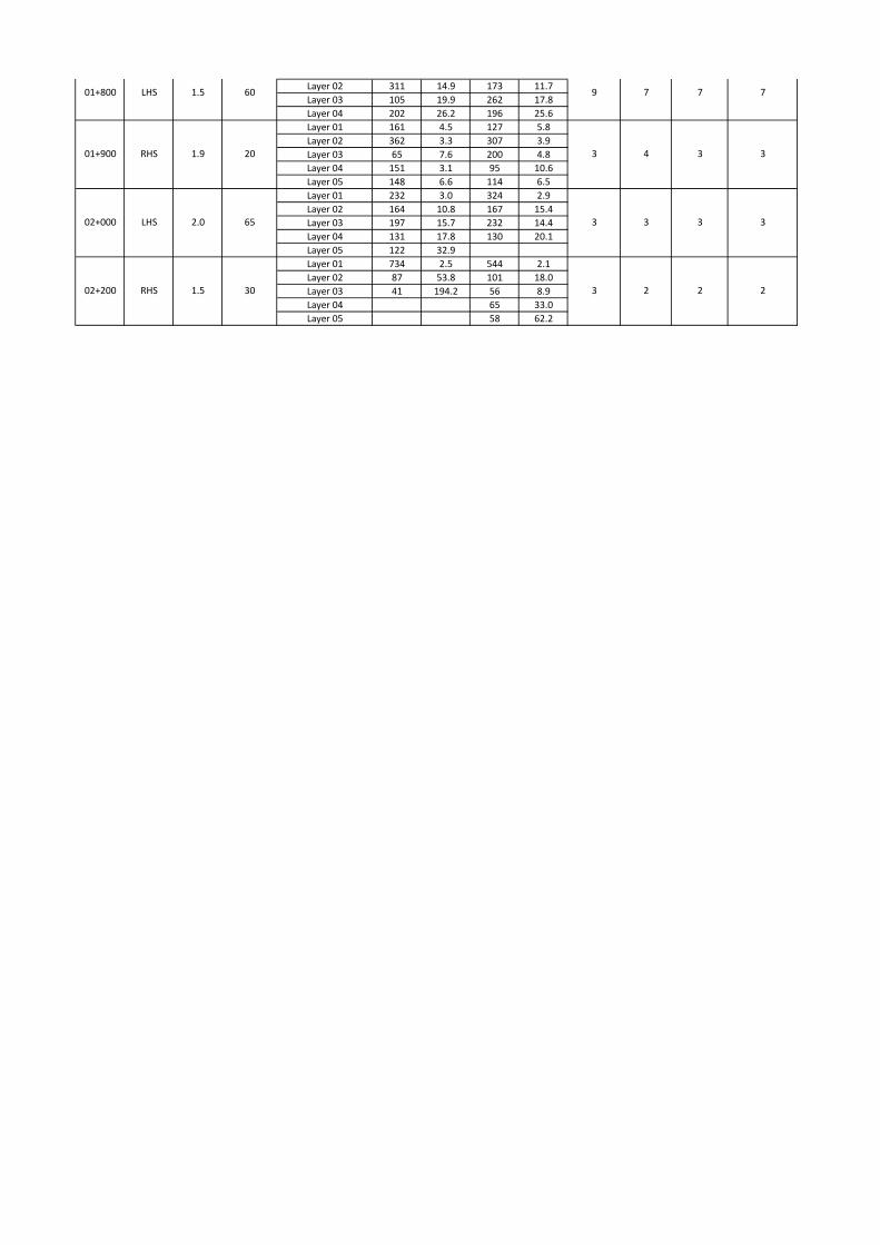
Layer 02 311 14.9 173 11.7
Layer 03 105 19.9 262 17.8
Layer 04 202 26.2 196 25.6
Layer 01 161 4.5 127 5.8
Layer 02 362 3.3 307 3.9
Layer 03 65 7.6 200 4.8
Layer 04 151 3.1 95 10.6
Layer 05 148 6.6 114 6.5
Layer 01 232 3.0 324 2.9
Layer 02 164 10.8 167 15.4
Layer 03 197 15.7 232 14.4
Layer 04 131 17.8 130 20.1
Layer 05 122 32.9
Layer 01 734 2.5 544 2.1
Layer 02 87 53.8 101 18.0
Layer 03 41 194.2 56 8.9
Layer 04 65 33.0
Layer 05 58 62.2
7
4
3
2
01+900
9
3
3
3
20 3 3
02+000 LHS 2.0
02+200 RHS 1.5 30 2 2
65 3 3
01+800 LHS 1.5 60 7 7
RHS 1.9
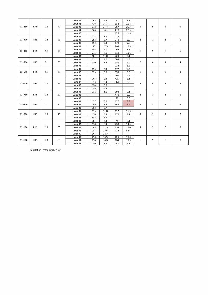
Layer 01 165 5.9 81 9.3
Layer 02 416 18.7 132 21.8
Layer 03 172 34.4 267 36.3
Layer 04 100 10.1 218 22.9
Layer 05 128 11.9
Layer 01 275 1.7 225 1.0
Layer 02 293 0.7 340 0.6
Layer 03 192 2.4 178 2.6
Layer 01 30 17.3 208 10.9
Layer 02 346 7.1 262 8.6
Layer 03 215 4.5 119 10.6
Layer 04 184 11.0 220 9.1
Layer 01 612 4.7 388 6.3
Layer 02 230 7.5 232 3.0
Layer 03 234 8.5
Layer 01 655 2.9 172 4.2
Layer 02 173 5.6 395 3.0
Layer 03 267 4.5
Layer 01 166 2.8 425 5.1
Layer 02 313 5.4 360 3.3
Layer 03 124 8.0
Layer 04 156 4.6
Layer 01 781 1.1 262 0.8
Layer 02 440 0.5
Layer 03 66 3.6
Layer 01 157 3.0 127 9.9
Layer 02 209 3.4 656 3.2
Layer 03 352 2.7
Layer 01 115 11.0 112 11.3
Layer 02 176 8.5 776 8.7
Layer 03 582 6.3
Layer 01 164 4.4 75 3.1
Layer 02 118 8.4 230 14.5
Layer 03 148 17.5 254 26.0
Layer 04 187 25.4 215 48.4
Layer 05 164 32.7
Layer 01 250 16.5 225 16.0
Layer 02 370 10.9 203 12.5
Layer 03 250 3.8 440 6.1
Correlation Factor is taken as 1
3
1
4
3
4
302+550 RHS 1.7 35
1.8 55
02+500 LHS 2.1 85
3
02+250 RHS 1.9 70 6 66
102+300 LHS 1
9
1
4
02+400 RHS 1.7 90 6 66
5
9
4
02+900 LHS 1.7 80 3 3
02+700 LHS 2.0 55 3 3
02+750 RHS 1.8 80 1 1
3
1
3
1
3
03+000 LHS 1.8 40 7 7
03+100 RHS 1.8 95 3 3
7
4
9
3
03+180 LHS 2.0 60 9 99 9
37.50 20.00 14.00 10.00 5.00 2.36 1.18 0.60 0.43 0.30 0.15 0.075
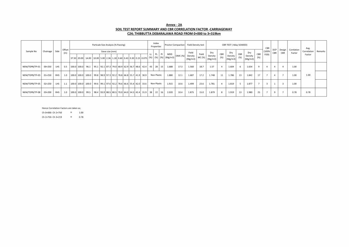
NEM/TDPB/TP-01 00+250 LHS 0.5 100.0 100.0 96.1 95.1 92.1 87.3 79.0 68.9 62.9 56.7 48.6 42.4 43 28 15 1.688 17.3 1.560 18.7 1.57 4 1.604 6 1.654 9 4 4 4 1.00
NEM/TDPB/TP-03 01+250 RHS 1.0 100.0 100.0 100.0 99.8 98.9 97.3 92.2 78.8 66.8 55.7 41.9 30.9 1.880 12.1 1.687 17.2 1.748 11 1.786 13 1.842 17 7 4 7 1.00
NEM/TDPB/TP-05 02+250 LHS 1.1 100.0 100.0 100.0 99.6 99.1 97.6 92.2 78.6 66.6 55.4 42.0 33.6 1.915 10.6 1.499 23.6 1.781 4 1.819 5 1.877 7 3 1 3 1.00
NEM/TDPB/TP-08 03+200 RHS 1.0 100.0 100.0 99.5 98.4 93.9 88.5 80.5 70.0 64.0 54.5 42.4 31.9 38 22 16 2.020 10.4 1.875 15.0 1.879 8 1.919 13 1.980 25 7 9 7 0.78 0.78
Hence Correlation Factors are taken as;
Ch 0+000- Ch 2+750 = 1.00
Ch 2+750- Ch 3+219 = 0.78
Non Plastic
Sieve size (mm)LL
(%)
CBR
(%)
Dry
Density
(Mg/m3)
MDD
(Mg/m3)OMC (%)
Field
Density
(Mg/m3)
Field
MC (%)
Non Plastic
Annex - 2A
SOIL TEST REPORT SUMMARY AND CBR CORRELATION FACTOR -CARRIAGEWAYC24; THIBBUTTA DEBARALAWA ROAD FROM 0+000 to 3+319km
Sample No Chainage SideOffset
(m)
Particale Size Analysis (% Passing) Index
Properties
DCP
CBR
Design
CBR Remarks
Corelation
FactorPL
(%)
PI
(%)
Avg.
Correlation
Factor
1.00
Proctor Compaction Field Density test CBR TEST ( 4day SOAKED)
CBR
(100%
FDD)Dry
Density
(Mg/m3)
Dry
Density
(Mg/m3)
CBR
(%)
CBR
(%)
37.50 20.00 14.00 10.00 5.00 2.36 1.18 0.60 0.43 0.30 0.15 0.075
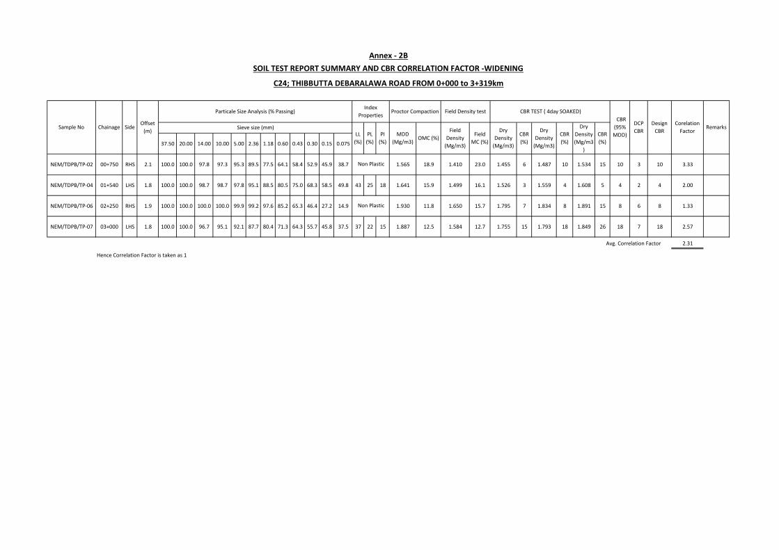
NEM/TDPB/TP-02 00+750 RHS 2.1 100.0 100.0 97.8 97.3 95.3 89.5 77.5 64.1 58.4 52.9 45.9 38.7 1.565 18.9 1.410 23.0 1.455 6 1.487 10 1.534 15 10 3 10 3.33
NEM/TDPB/TP-04 01+540 LHS 1.8 100.0 100.0 98.7 98.7 97.8 95.1 88.5 80.5 75.0 68.3 58.5 49.8 43 25 18 1.641 15.9 1.499 16.1 1.526 3 1.559 4 1.608 5 4 2 4 2.00
NEM/TDPB/TP-06 02+250 RHS 1.9 100.0 100.0 100.0 100.0 99.9 99.2 97.6 85.2 65.3 46.4 27.2 14.9 1.930 11.8 1.650 15.7 1.795 7 1.834 8 1.891 15 8 6 8 1.33
NEM/TDPB/TP-07 03+000 LHS 1.8 100.0 100.0 96.7 95.1 92.1 87.7 80.4 71.3 64.3 55.7 45.8 37.5 37 22 15 1.887 12.5 1.584 12.7 1.755 15 1.793 18 1.849 26 18 7 18 2.57
2.31
Hence Correlation Factor is taken as 1
Non Plastic
MDD
(Mg/m3)OMC (%)
Proctor Compaction
PL
(%)
PI
(%)
Field Density test
Design
CBR Field
Density
(Mg/m3)
Field
MC (%)
Dry
Density
(Mg/m3)
DCP
CBRDry
Density
(Mg/m3)
CBR
(%)
Dry
Density
(Mg/m3
)
CBR
(%)
CBR
(%)
CBR TEST ( 4day SOAKED)
Avg. Correlation Factor
Non Plastic
Sieve size (mm)
Annex - 2B
SOIL TEST REPORT SUMMARY AND CBR CORRELATION FACTOR -WIDENING
C24; THIBBUTTA DEBARALAWA ROAD FROM 0+000 to 3+319km
Sample No Chainage SideOffset
(m)
Index
Properties
Corelation
FactorRemarks
LL
(%)
Particale Size Analysis (% Passing)
CBR
(95%
MDD)
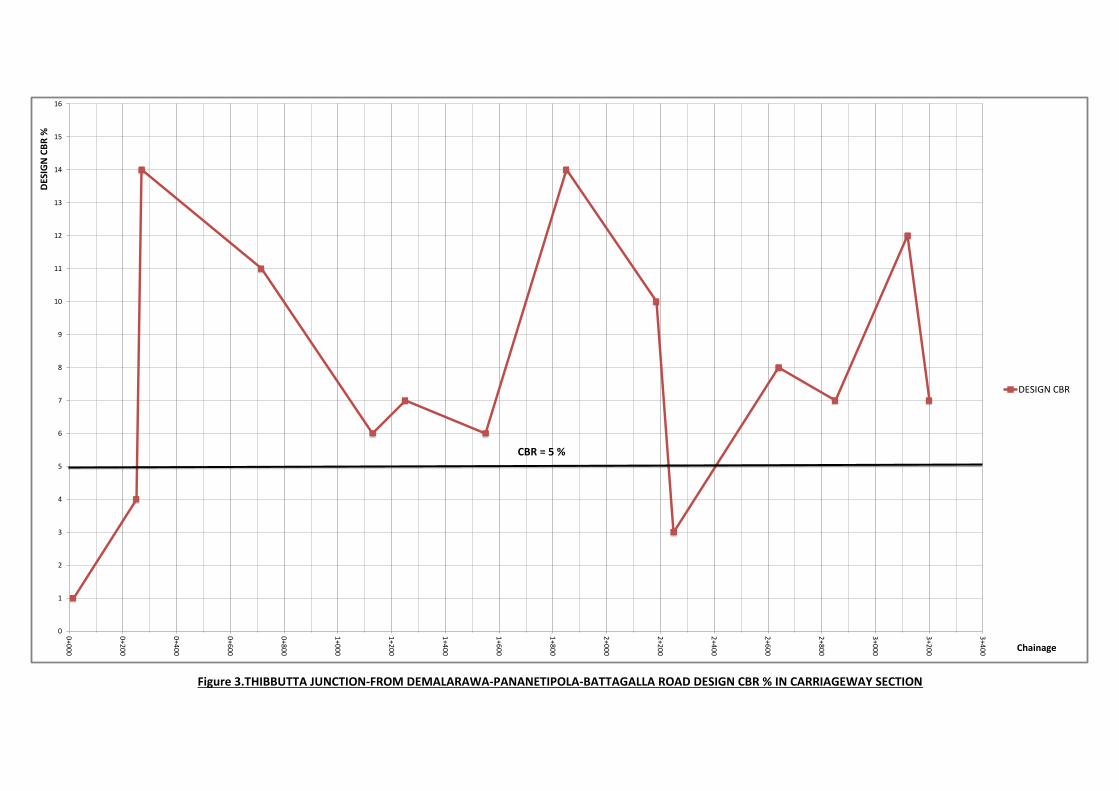
Figure 3.THIBBUTTA JUNCTION-FROM DEMALARAWA-PANANETIPOLA-BATTAGALLA ROAD DESIGN CBR % IN CARRIAGEWAY SECTION
0
1
2
3
4
5
6
7
8
9
10
11
12
13
14
15
16
0+0
00
0+2
00
0+4
00
0+6
00
0+8
00
1+0
00
1+2
00
1+4
00
1+6
00
1+8
00
2+0
00
2+2
00
2+4
00
2+6
00
2+8
00
3+0
00
3+2
00
3+4
00
DES
IGN
CB
R %
Chainage
DESIGN CBR
CBR = 5 %
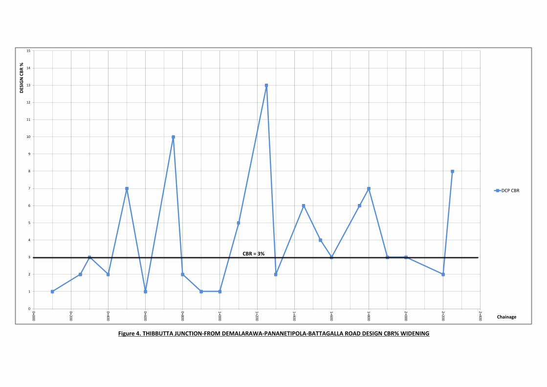
Figure 4. THIBBUTTA JUNCTION-FROM DEMALARAWA-PANANETIPOLA-BATTAGALLA ROAD DESIGN CBR% WIDENING
0
1
2
3
4
5
6
7
8
9
10
11
12
13
14
15
0+0
00
0+2
00
0+4
00
0+6
00
0+8
00
1+0
00
1+2
00
1+4
00
1+6
00
1+8
00
2+0
00
2+2
00
2+4
00
DES
IGN
CB
R %
Chainage
DCP CBR
CBR = 3%
From to TYPE THICKNESS TYPE THICKNESS TYPE THICKNESS
Concrete 100 6x4 Rock 90 23.9
0+015 Concrete 100 Gravel 50 6x4 Rock 80 28.3
Ch
0+195
CH
0+2456x4 Rock 100 11.0 11
Concrete 90 6x4 Rock 95 23.1
0+250 Concrete 95 13.3
0+270 Concrete 95 13.3
Ch
0+275
Ch
0+3406x4 Rock 100 11.0 10
Ch
0+340
Ch
0+367Concrete 95 6x4 Rock 90 13.3 13
Ch
0+367
Ch
0+3776x4 Rock 90 9.9 10
Ch
0+377
Ch
0+485Concrete 100 14.0 14
Ch
0+485
Ch
0+6106x4 Rock 95 13.3 13
Ch
0+610
Ch
0+655Concrete 100 6x4 Rock 90 14.0 14
Ch
0+655
Ch
0+7306x4 Rock 100 11.0 11
Ch
0+730
Ch
0+895Concrete 100 Gravel 30 6x4 Rock 100 28.0 28
Ch
0+895
Ch
1+0106x4 Rock 90 9.9 10
Ch
1+010
Ch
1+122Concrete 80
Aggregate
Mix25 13.7 14
6x4 Rock 105 11.6 12
1+250 6x4 Rock 150 16.5 17
Ch
1+315
Ch
1+535
6x4 Rock 105
1+540Dark Brown
Silty Clay1000
Ch
1+665
Ch
2+015Ch
2+015
Ch
2+055Concrete 110
Aggregate
Mix Soil100 25.4 25
Ch
2+055
Ch
2+200
6x4 Rock 90 9.9
2+250 6x4 Rock 120 13.2
2+700 6x4 Rock 90 9.9
Ch
2+810
Ch
3+0522+850
Interlock
Section75 10.5 11
ANNEX 3
EXISTING LAYER THICKNESSES
THIBBUTTA JUNCTION FROM DEMALARAWA PANANETIPOLA BATTAGALLA ROAD CH 0+000-CH 3+219
LAYER 01 LAYER 02
Remarks Test
Loction
Structural
No
Min.
Structural No
Chainage LAYER 03
Ch
0+000
Ch
0+115
Ch
0+245
Ch
0+275
24
13
12
10Ch
2+200
Ch
1+122
Ch
1+315
Ch
1+535
Ch
1+665
Ch
2+810
Asphalt Section
Soil Section
Soil Section
11.55
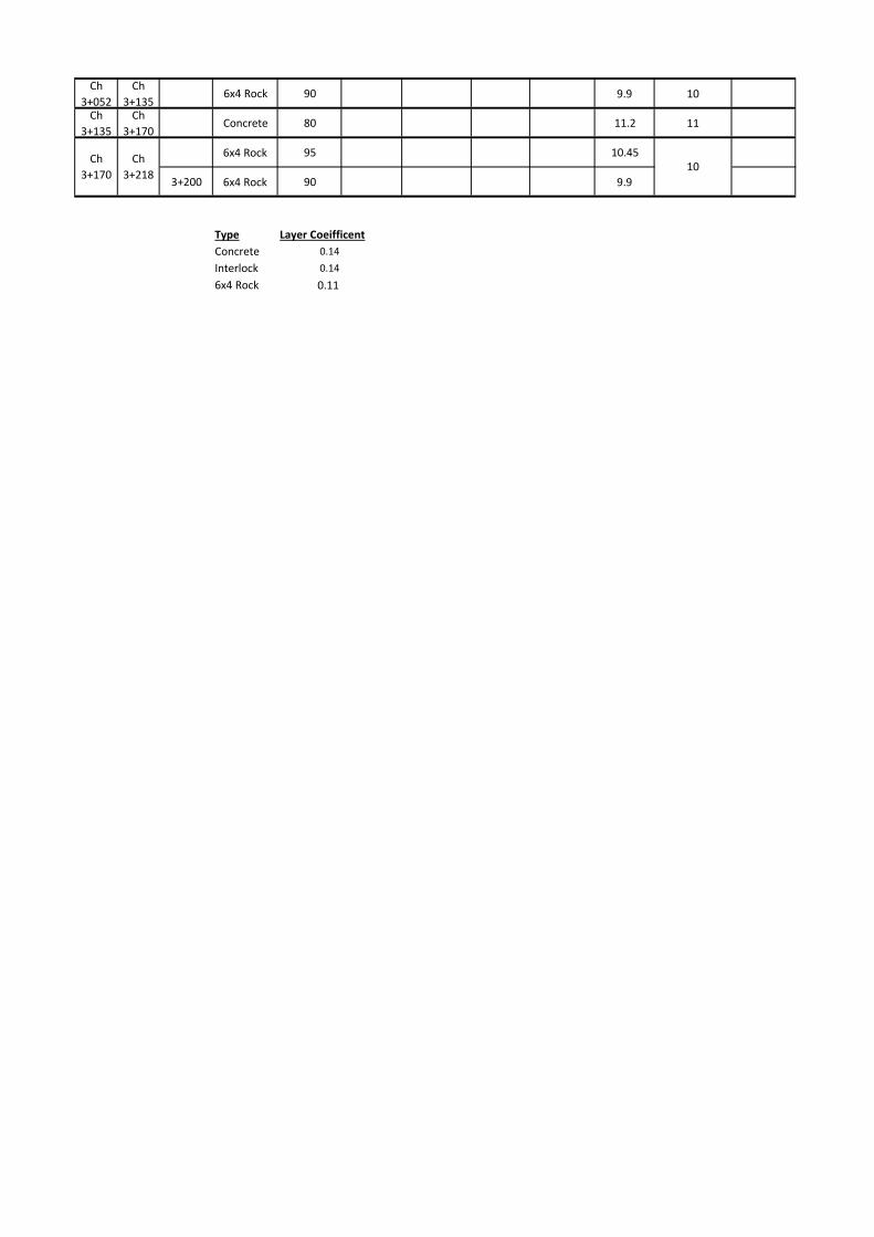
Ch
3+052
Ch
3+1356x4 Rock 90 9.9 10
Ch
3+135
Ch
3+170Concrete 80 11.2 11
6x4 Rock 95 10.45
3+200 6x4 Rock 90 9.9
Type Layer Coeifficent
Concrete 0.14
Interlock 0.14
6x4 Rock 0.11
Ch
3+170
Ch
3+21810
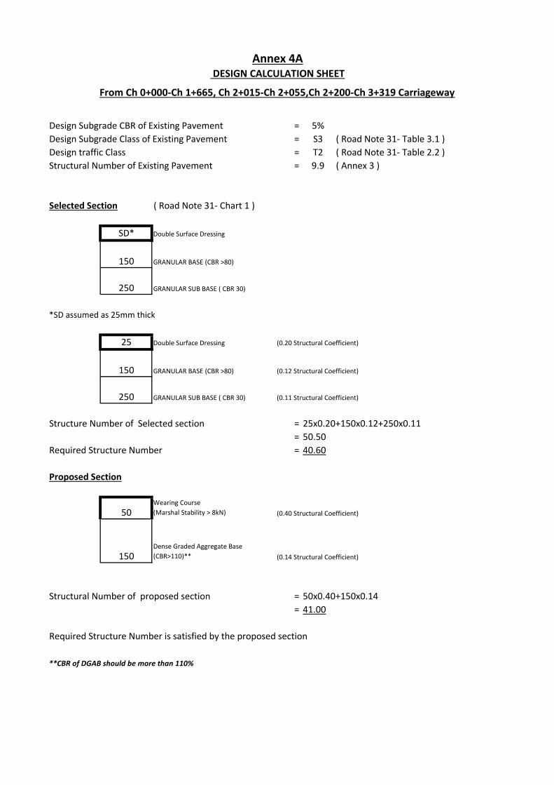
Design Subgrade CBR of Existing Pavement = 5%
Design Subgrade Class of Existing Pavement = S3 ( Road Note 31- Table 3.1 )
Design traffic Class = T2 ( Road Note 31- Table 2.2 )
Structural Number of Existing Pavement = 9.9 ( Annex 3 )
Selected Section ( Road Note 31- Chart 1 )
SD* Double Surface Dressing
GRANULAR BASE (CBR >80)
GRANULAR SUB BASE ( CBR 30)
*SD assumed as 25mm thick
25 Double Surface Dressing (0.20 Structural Coefficient)
GRANULAR BASE (CBR >80) (0.12 Structural Coefficient)
GRANULAR SUB BASE ( CBR 30) (0.11 Structural Coefficient)
Structure Number of Selected section = 25x0.20+150x0.12+250x0.11
= 50.50
Required Structure Number = 40.60
Proposed Section
50Wearing Course
(Marshal Stability > 8kN) (0.40 Structural Coefficient)
Dense Graded Aggregate Base
(CBR>110)** (0.14 Structural Coefficient)
Structural Number of proposed section = 50x0.40+150x0.14
= 41.00
Required Structure Number is satisfied by the proposed section
**CBR of DGAB should be more than 110%
250
150
Annex 4A DESIGN CALCULATION SHEET
From Ch 0+000-Ch 1+665, Ch 2+015-Ch 2+055,Ch 2+200-Ch 3+319 Carriageway
150
250
150
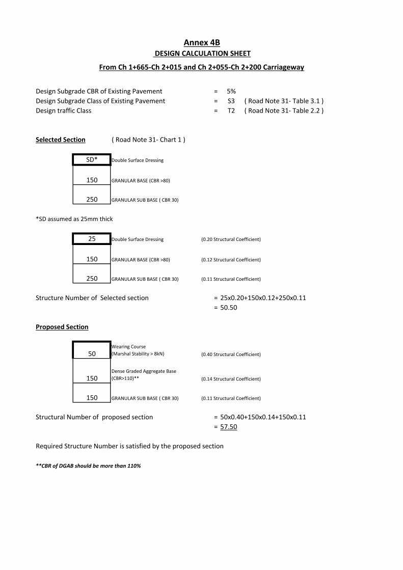
Design Subgrade CBR of Existing Pavement = 5%
Design Subgrade Class of Existing Pavement = S3 ( Road Note 31- Table 3.1 )
Design traffic Class = T2 ( Road Note 31- Table 2.2 )
Selected Section ( Road Note 31- Chart 1 )
SD* Double Surface Dressing
GRANULAR BASE (CBR >80)
GRANULAR SUB BASE ( CBR 30)
*SD assumed as 25mm thick
25 Double Surface Dressing (0.20 Structural Coefficient)
GRANULAR BASE (CBR >80) (0.12 Structural Coefficient)
GRANULAR SUB BASE ( CBR 30) (0.11 Structural Coefficient)
Structure Number of Selected section = 25x0.20+150x0.12+250x0.11
= 50.50
Proposed Section
50Wearing Course
(Marshal Stability > 8kN) (0.40 Structural Coefficient)
Dense Graded Aggregate Base
(CBR>110)** (0.14 Structural Coefficient)
GRANULAR SUB BASE ( CBR 30) (0.11 Structural Coefficient)
Structural Number of proposed section = 50x0.40+150x0.14+150x0.11
= 57.50
Required Structure Number is satisfied by the proposed section
**CBR of DGAB should be more than 110%
150
150
Annex 4B DESIGN CALCULATION SHEET
150
250
150
250
From Ch 1+665-Ch 2+015 and Ch 2+055-Ch 2+200 Carriageway
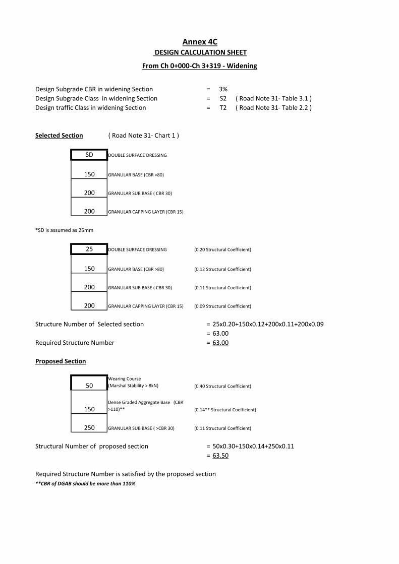
Design Subgrade CBR in widening Section = 3%
Design Subgrade Class in widening Section = S2 ( Road Note 31- Table 3.1 )
Design traffic Class in widening Section = T2 ( Road Note 31- Table 2.2 )
Selected Section ( Road Note 31- Chart 1 )
SD DOUBLE SURFACE DRESSING
GRANULAR BASE (CBR >80)
GRANULAR SUB BASE ( CBR 30)
GRANULAR CAPPING LAYER (CBR 15)
*SD is assumed as 25mm
25 DOUBLE SURFACE DRESSING (0.20 Structural Coefficient)
GRANULAR BASE (CBR >80) (0.12 Structural Coefficient)
GRANULAR SUB BASE ( CBR 30) (0.11 Structural Coefficient)
GRANULAR CAPPING LAYER (CBR 15) (0.09 Structural Coefficient)
Structure Number of Selected section = 25x0.20+150x0.12+200x0.11+200x0.09
= 63.00
Required Structure Number = 63.00
Proposed Section
50Wearing Course
(Marshal Stability > 8kN) (0.40 Structural Coefficient)
Dense Graded Aggregate Base (CBR
>110)** (0.14** Structural Coefficient)
GRANULAR SUB BASE ( >CBR 30) (0.11 Structural Coefficient)
Structural Number of proposed section = 50x0.30+150x0.14+250x0.11
= 63.50
Required Structure Number is satisfied by the proposed section
**CBR of DGAB should be more than 110%
250
200
150
Annex 4C DESIGN CALCULATION SHEET
From Ch 0+000-Ch 3+319 - Widening
150
200
150
200
200
Annex 5- Traffic Data