Embed Size (px)
Citation preview
4
Präzisions-Vollhartmetall-Verzahnungswerkzeuge
Precision solid carbide gearcutting tools
4

FirmengeschichteCorporate history
Erfahrung – Kompetenz – Qualität
1936 wurde die Firma DIAMETAL AG/SA in Biel, Schweiz, gegründet. Die Firma hat sich von Anfang an auf die Produktion und Entwicklung von Hartmetall-Werkzeugen und Ver-schleissteilen aus Hartstoffen sowie auf Diamant- und CBN-Schleifwerkzeuge spezialisiert.1973 wurde DIAMETAL FRANCE in Oltingue und 1995 DIAMETAL ITALIA in Busto Arsizio eröffnet. Indem DIAMETAL Hartmetall-Schneidwerkzeuge und Verschleissteile mit den eigenen Schleifwerkzeugen produziert, entstehen einmalige Synergien, die der internationale Kundenkreis zu schätzen weiss. Jahrelange Forschung und Entwicklung verschafft uns ein hohes technisches Wissen, welches wir für die Lösung der Probleme unserer Kunden optimal einsetzen können. Wir bieten Produkte von höchster Qualität und sind nach ISO 9001:2000, ISO 14001:1996 und OHSAS 18001:1999 zertifiziert.
Experience – Competence – Quality
DIAMETAL AG/SA was founded in Biel, Switzerland, in 1936. Right from the beginning the company has specialised in the production and development of carbide tools and carbide wear parts as well as Diamond and CBN grinding tools. DIAMETAL FRANCE was opened in Oltingue in 1973, and DIAMETAL ITALIA in Busto Arsizio in 1995. By using our own grinding tools to produce carbide cutting tools and carbide wear parts, DIAMETAL creates unique synergies that are highly valued and appreciated by our international customers. The wealth of technical know-how gathered over many years of research and development is applied to find the optimum solutions to our customers’ problems.We offer products of the highest quality and have ISO 9001:2000, ISO 14001:1996 and OHSAS 18001:1999 certification.
4
5
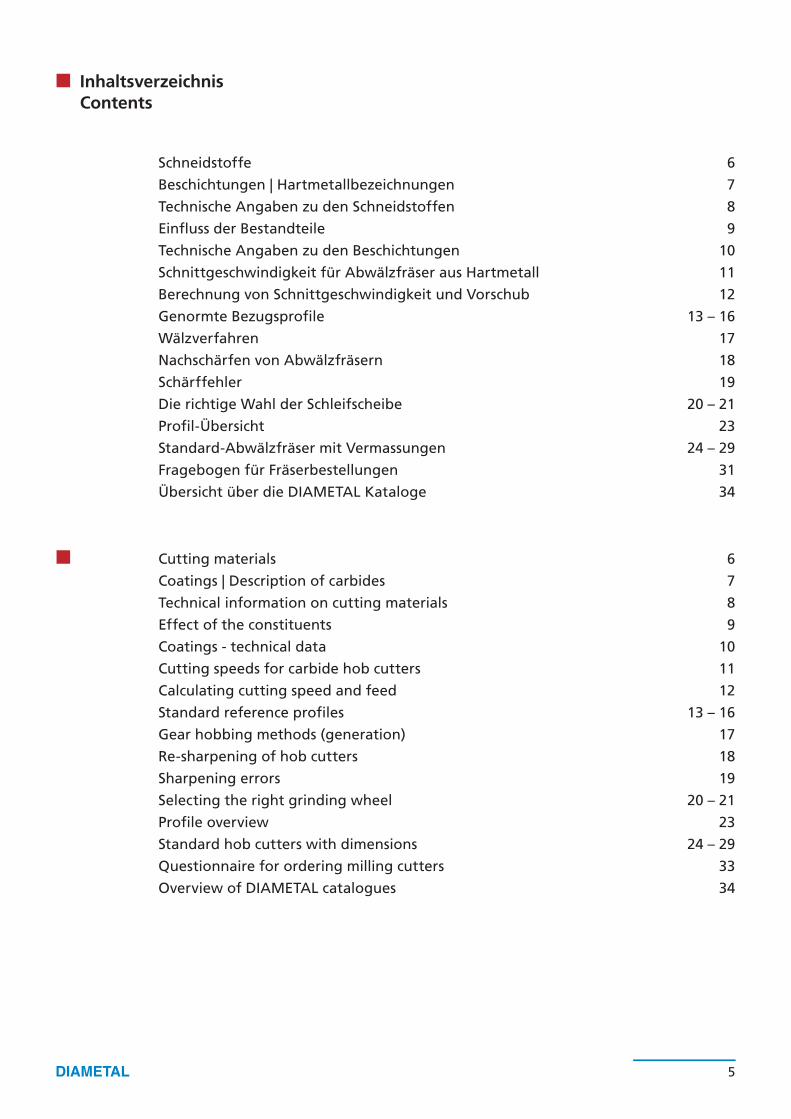
InhaltsverzeichnisContents
Schneidstoffe
Beschichtungen | Hartmetallbezeichnungen
Technische Angaben zu den Schneidstoffen
Einfluss der Bestandteile
Technische Angaben zu den Beschichtungen
Schnittgeschwindigkeit für Abwälzfräser aus Hartmetall
Berechnung von Schnittgeschwindigkeit und Vorschub
Genormte Bezugsprofile
Wälzverfahren
Nachschärfen von Abwälzfräsern
Schärffehler
Die richtige Wahl der Schleifscheibe
Profil-Übersicht
Standard-Abwälzfräser mit Vermassungen
Fragebogen für Fräserbestellungen
Übersicht über die DIAMETAL Kataloge
6
7
8
9
10
11
12
13 – 16
17
18
19
20 – 21
23
24 – 29
31
34
Cutting materials
Coatings | Description of carbides
Technical information on cutting materials
Effect of the constituents
Coatings - technical data
Cutting speeds for carbide hob cutters
Calculating cutting speed and feed
Standard reference profiles
Gear hobbing methods (generation)
Re-sharpening of hob cutters
Sharpening errors
Selecting the right grinding wheel
Profile overview
Standard hob cutters with dimensions
Questionnaire for ordering milling cutters
Overview of DIAMETAL catalogues
6
7
8
9
10
11
12
13 – 16
17
18
19
20 – 21
23
24 – 29
33
34
6 7
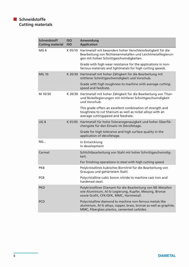
SchneidstoffeCutting materials
SchneidstoffCutting material
ISOISO
AnwendungApplication
MG 6 K 05/10 Hartmetall mit besonders hoher Verschleissfestigkeit für die Bearbeitung von Nichteisenmetallen und Leichtmetalllegierun-gen mit hohen Schnittgeschwindigkeiten.
Grade with high wear resistance for the applications in non-ferrous materials and lightmetals for high cutting speeds.
MG 10 K 20/30 Hartmetall mit hoher Zähigkeit für die Bearbeitung mitmittlerer Schnittgeschwindigkeit und Vorschub.
Grade with high toughness to machine with average cutting-speed and feedrate.
M 10/30 K 20/30 Hartmetall mit hoher Zähigkeit für die Bearbeitung von Titan-und Nickellegierungen mit mittlerer Schnittgeschwindigkeitund Vorschub.
This grade offers an excellent combination of strength andtoughness to cut titanium as well as nickel alloys with an average cuttingspeed and feedrate.
UG 8 K 01/05 Hartmetall für hohe Toleranzgenauigkeit und hoher Oberflä-chengüte für den Einsatz im Décolletage.
Grade for high tolerance and high surface quality in the application of décolletage.
NG... In EntwicklungIn development
Cermet Schlichtbearbeitung von Stahl mit hoher Schnittgeschwindig-keit.
For finishing operations in steel with high cutting speed.
PKB Polykristallines kubisches Bornitrid für die Bearbeitung von Grauguss und gehärtetem Stahl.
PCB Polycristalline cubic boron nitride to machine cast iron and hardened steel.
PKD Polykristalliner Diamant für die Bearbeitung von NE-Metallenwie Aluminium, Al-Si-Legierung, Kupfer, Messing, Bronze sowie Grafit, CFK/GFK, MMC, Hartmetall.
PCD Polycristalline diamond to machine non-ferrous metals like aluminium, Al-Si alloys, copper, brass, bronze as well as graphite, MMC, Fiberglass plastics, cemented carbides.

D 10
D 20
D 30
D 32
D 33
D 40
6 7
MG Micrograin Korngrösse 0,6 – 1,0 µm Grain size 0.6 – 1.0 µm
UG Ultragrain Korngrösse 0,3 – 0,6 µm Grain size 0.3 – 0.6 µm
NG Nanograin Korngrösse < 0,3 µm Grain size < 0.3 µm
HartmetallbezeichnungenDescription of carbides
BeschichtungenCoatings
Material AnwendungApplication
TiNUniversell einsetzbar
Universal application
TiCNFeinbearbeitung
Finishing
TiAINStahl, Nickellegierung, Aluminium
Steel, nickel alloys, aluminium
TiAINStahl >45 HRc, Inconell
Steel >45 HRc, Inconell
TiAINRostbeständiger Stahl, Titanlegierungen, NE-Metalle
Stainless steel, titan alloys, non-ferrous metals
AITiN
Titan-, Nickellegierungen, austenitische Stähle, Hartbearbeitung
Titan and nickel alloys, austenitic steel, hard machining

8 9
Technische Angaben zu den SchneidstoffenTechnical information on cutting materials
Hartmetallsorten / Carbide grades
MG 6 MG 10 M 10/30 UG 8 Cermet
Zusammensetzung WCComposition WC
in%per%
94 90 90 92 16
Zusammensetzung CoComposition Co
in%per%
6 10 10 8 11
Zusammensetzung TiC/TinComposition TiC/TiN
in%per%
50
KorngrösseGrain size
µmµm
0.8 0.7 0.8 0.4
BiegebruchfestigkeitTransverse rupture strength
N/mm2
N/mm2 2700 3200 3000 3150
DichteDensity
g/cm3
g/cm3 14.90 14.50 14.45 14.50 7.00
VickershärteVickers hardness
HVHV
1800 1600 1580 1900 1580
8 9
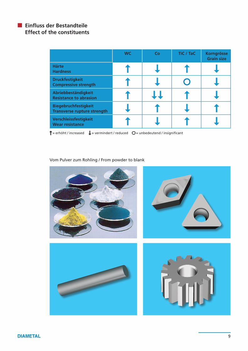
Einfluss der BestandteileEffect of the constituents
Vom Pulver zum Rohling / From powder to blank
HärteHardness
DruckfestigkeitCompressive strength
AbriebbeständigkeitResistance to abrasion
BiegebruchfestigkeitTransverse rupture strength
VerschleissfestigkeitWear resistance
WC Co TiC / TaC KorngrösseGrain size
= erhöht / increased = vermindert / reduced = unbedeutend / insignificant

10 11
Einlagig / Monolayer Mehrlagig / Multilayer
Die Vorteile beschichteter Werkzeuge
– Erhöhte Produktivität– Weniger Maschinenstillstände– Reduzierte Bearbeitungszeit– Erhöhte Schnittgeschwindigkeit– Bessere Oberflächengüte
The advantages of coated tools
– Increased productivity– Lower standstill– Lower machining time– Increased cutting speed– Better surface quality
Technische Angaben zu den BeschichtungenCoatings - technical data
1 µm 2 µm
BeschichtungCoating
D10TiN
D20TiCN
D30TiAIN
D32TiAIN
D33TiAIN
D40AITiN
Mikrohärte (HV 0,05)Microhardness (HV 0.05) 2300 3000 3300 3300 3000 3600
SchichtdickeThickness of the coating
1–4 µm 1–4 µm 1–3 µm 1–3 µm 1–4 µm 1–4 µm
Reibkoeffizient mit Stahl trockenCoefficient of friction with dry steel
0.4 0.4 0.4 0.4 0.2 0.7
Maximale AnwendungstemperaturMax. temperature of application
600 °C 400 °C 800 °C 900 °C 800 °C 800 °C
SchichtaufbauCoating structure
EinlagigMonolayer
GradiertGraduated
NanostrukturNanostructure
EinlagigMonolayer
MehrlagigMultilayer
EinlagigMonolayer
10 11
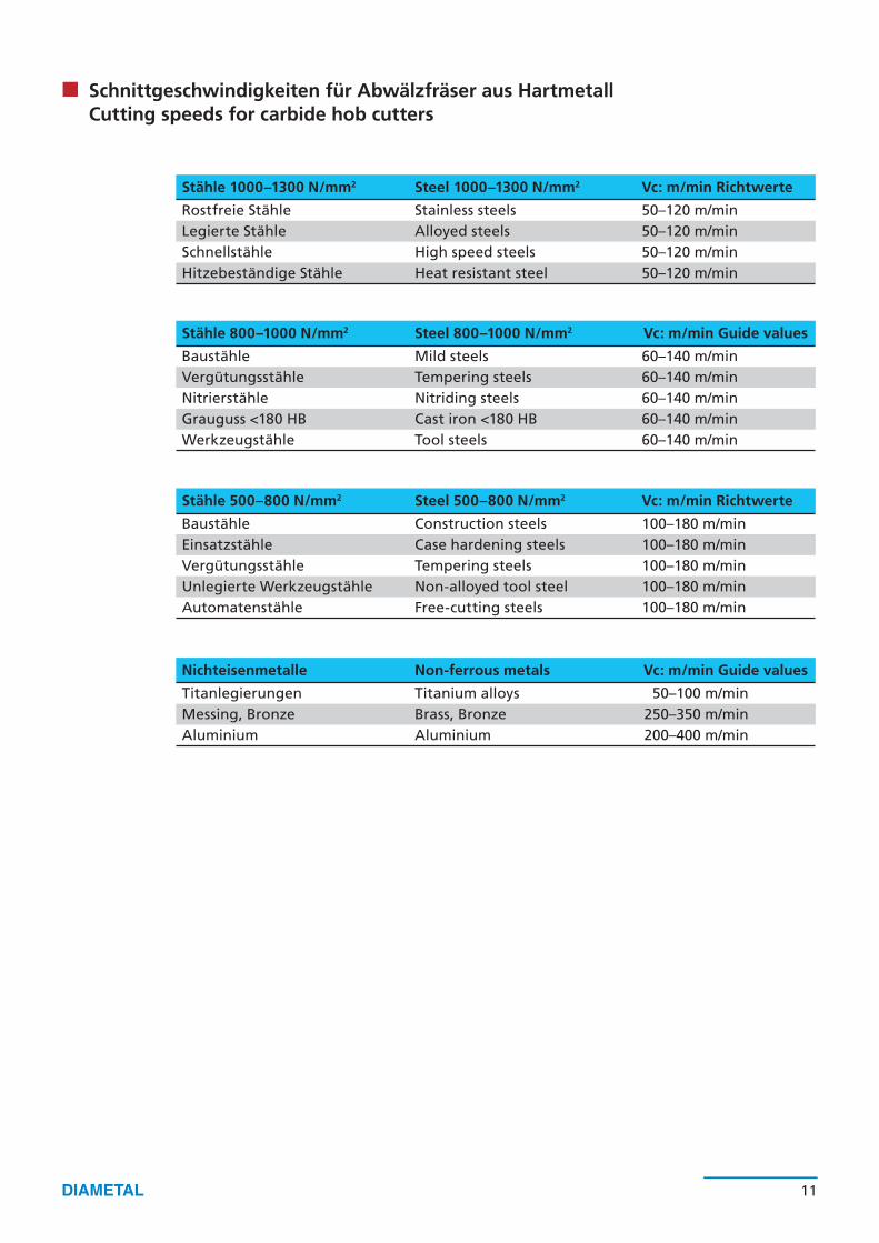
Schnittgeschwindigkeiten für Abwälzfräser aus HartmetallCutting speeds for carbide hob cutters
Stähle 1000–1300 N/mm2 Steel 1000–1300 N/mm2 Vc: m/min Richtwerte
Rostfreie Stähle Stainless steels 50–120 m/minLegierte Stähle Alloyed steels 50–120 m/minSchnellstähle High speed steels 50–120 m/minHitzebeständige Stähle Heat resistant steel 50–120 m/min
Stähle 800–1000 N/mm2 Steel 800–1000 N/mm2 Vc: m/min Guide values
Baustähle Mild steels 60–140 m/minVergütungsstähle Tempering steels 60–140 m/minNitrierstähle Nitriding steels 60–140 m/minGrauguss <180 HB Cast iron <180 HB 60–140 m/minWerkzeugstähle Tool steels 60–140 m/min
Stähle 500–800 N/mm2 Steel 500–800 N/mm2 Vc: m/min Richtwerte
Baustähle Construction steels 100–180 m/minEinsatzstähle Case hardening steels 100–180 m/minVergütungsstähle Tempering steels 100–180 m/minUnlegierte Werkzeugstähle Non-alloyed tool steel 100–180 m/minAutomatenstähle Free-cutting steels 100–180 m/min
Nichteisenmetalle Non-ferrous metals Vc: m/min Guide values
Titanlegierungen Titanium alloys 50–100 m/minMessing, Bronze Brass, Bronze 250–350 m/minAluminium Aluminium 200–400 m/min
1500
0 t/
min
1000
0 t/
min
800
0 t/
min
700
0 t/
min
600
0 t/
min
500
0 t/
min
400
0 t/m
in 3
000 t/min
2500 t/m
in
2000 t/min
1500 t/min
1200 t/min
1000 t/min
750 t/min
500 t/min
400 t/min
12 13
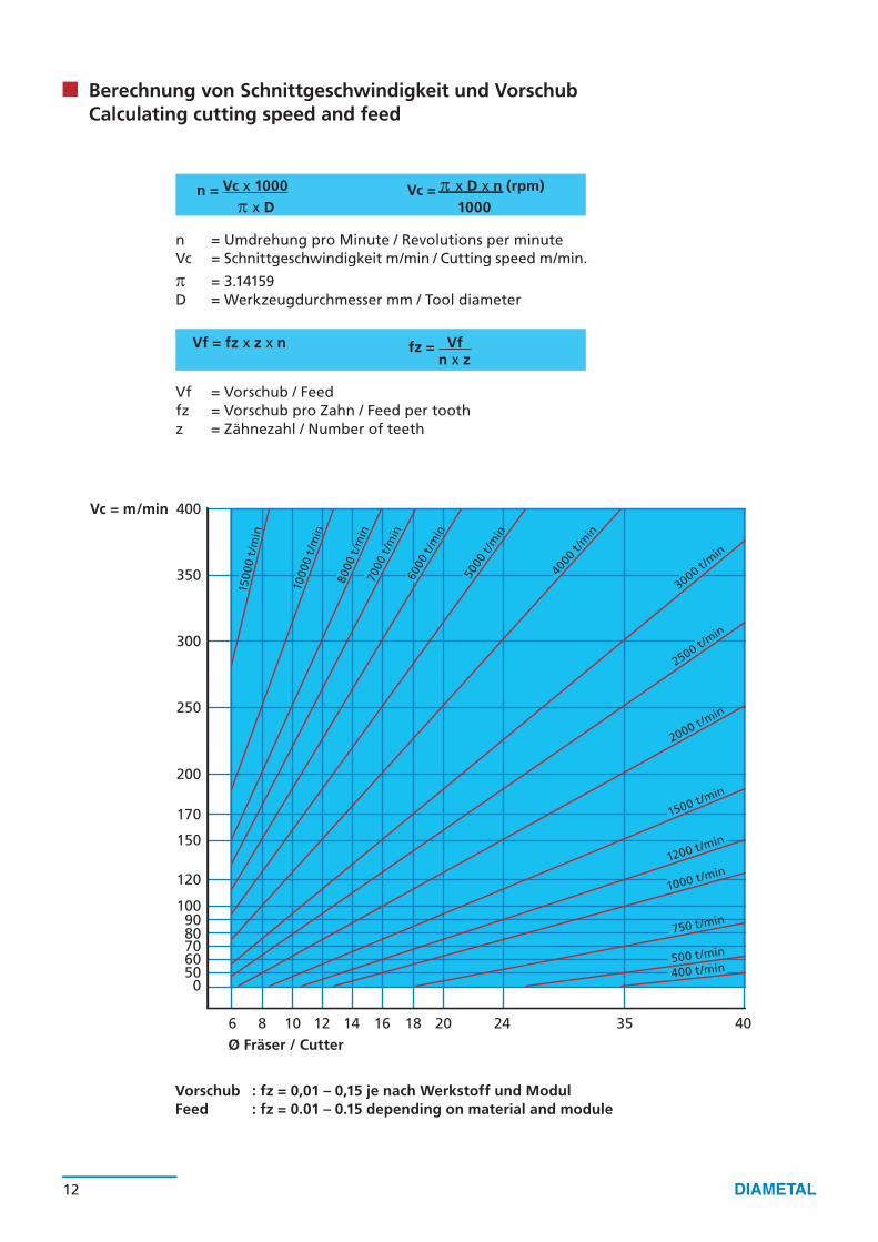
Vorschub : fz = 0,01 – 0,15 je nach Werkstoff und ModulFeed : fz = 0.01 – 0.15 depending on material and module
Berechnung von Schnittgeschwindigkeit und VorschubCalculating cutting speed and feed
Vc = m/min
n = Vc x 1000 Vc = π x D x n (rpm)
π x D 1000
n = Umdrehung pro Minute / Revolutions per minuteVc = Schnittgeschwindigkeit m/min / Cutting speed m/min.
π = 3.14159D = Werkzeugdurchmesser mm / Tool diameter
Vf = fz x z x n fz = Vf n x z
Vf = Vorschub / Feedfz = Vorschub pro Zahn / Feed per toothz = Zähnezahl / Number of teeth
400
350
300
250
200
170
150
120
1009080706050
0
6 8 10 12 14 16 18 20 24 35 40 Ø Fräser / Cutter
h P
h aP
h fP
c
fP
h wP
c
aαP=20° ρ
P= • m
SP= P ep= P
12 13
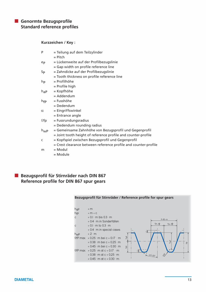
Kurzzeichen / Key :
P = Teilung auf dem Teilzylinder = PitcheP = Lückenweite auf der Profilbezugslinie = Gap width on profile reference lineSP = Zahndicke auf der Profilbezugslinie = Tooth thickness on profile reference linehP = Profilhöhe = Profile highhaP = Kopfhöhe = AddendumhfP = Fusshöhe = Dedendumα = Eingriffswinkel = Entrance angleρfp = Fussrundungsradius = Dedendum rounding radiushwP = Gemeinsame Zahnhöhe von Bezugsprofil und Gegenprofil = Joint tooth height of reference profile and counter-profilec = Kopfspiel zwischen Bezugsprofil und Gegenprofil = Crest clearance between reference profile and counter-profilem = Modul = Module
haP = mhfP = m + cc = 0.1 · m bis 0.3 · m = 0.4 · m in Sonderfällenc = 0.1 · m to 0.3 · m = 0.4 · m in special caseshwP = 2 · mρfP max. = 0.25 · m bei c = 0.17 · m = 0.38 · m bei c = 0.25 · m = 0.45 · m bei c = 0.30 · mρfP max. = 0.25 · m at c = 0.17 · m = 0.38 · m at c = 0.25 · m = 0.45 · m at c = 0.30 · m
Bezugsprofil für Stirnräder nach DIN 867Reference profile for DIN 867 spur gears
Bezugsprofil für Stirnräder / Reference profile for spur gears
Genormte BezugsprofileStandard reference profiles

SPO
fPO
h PO
20°
h aPO
h P
ρρ aP
O
SPO
h POh P
q
h aPO
20°fPO
ρρ aP
O
20°
SPO
h POh P
h aPO
fPO
ρρ aP
O
q
20°
SPO
h POh P
h aPO
fPO
ρρ aP
O
14 15
DIN 3972 – Kurzzeichen:
Wälzfräser-Bezugsprofile nach DIN 3972DIN 3972 hob cutter reference profiles
Bezugsprofil II / Reference profile II
Bezugsprofil I / Reference profile I
Bezugsprofil III / Reference profile III
Bezugsprofil IV / Reference profile IV
haP0 = Kopfhöhe des BezugsprofilshP = Profilhöhe des Rades =
FrästiefehP0 = Profilhöhe des BezugsprofilsSP0 = ZahndickeρaP0 = KopfrundungsradiusρfP0 = Fussrundungsradius
DIN 3972 – Key:
haP0 = Addendum of the reference
hP = Profile height of the wheel=
milling depthhP0 = Profile height of the reference
profile SP0 = Tooth thicknessρaP0 = Addendum rounding radiusρfP0 = Dedendum rounding radius
haP0 = 1.167 · mhP = 2.167 · mhP0 = 2.367 · mρaP0 ≈ 0.2 · mρfP0 ≈ 0.2 · mSP0 = · m
für Fertigbearbeitungfor finishing
² π
haP0 = 1.250 · mhP = 2.250 · mhP0 = 2.450 · mρaP0 ≈ 0.2 · mρfP0 ≈ 0.2 · mSP0 = · m
für Fertigbearbeitungfor finishing
² π
haP0 = 1.25 · m + 0.25 ³ mhP = 2.250 · mhP0 = 2.450 · mρaP0 ≈ 0.2 · mρfP0 ≈ 0.2 · mSP0 = · mq = 0.25 ³ m · sin 20°für Vorbereitung zum Schleifen od. Schabenfor preparing for grinding or scrubbing
√
√² π
haP0 = 1.25 · m + 0.60 ³ mhP = 2.250 · mhP0 = 2.450 · mρaP0 ≈ 0.2 · mρfP0 ≈ 0.2 · mSP0 = · mq = 0.6 ³ m · sin 20°für Vorbereitung zum Schlichtenfor preparing for finishing
√
√² π
15°
20°
SPO
h Pw h P
O
h fPO
h P
fPO
ρρ aP
O
15°
20°
SPO
h Pw h P
O
h fPO
fPO
ρρ aP
O
h P
1 °5
20°
ρ aPO
SPO
h Pw h P
O
h fPO
fPO
ρ
15°
20°
ρ aPO
SPO
h Pw h P
O
h fPO
fPO
ρ
14 15
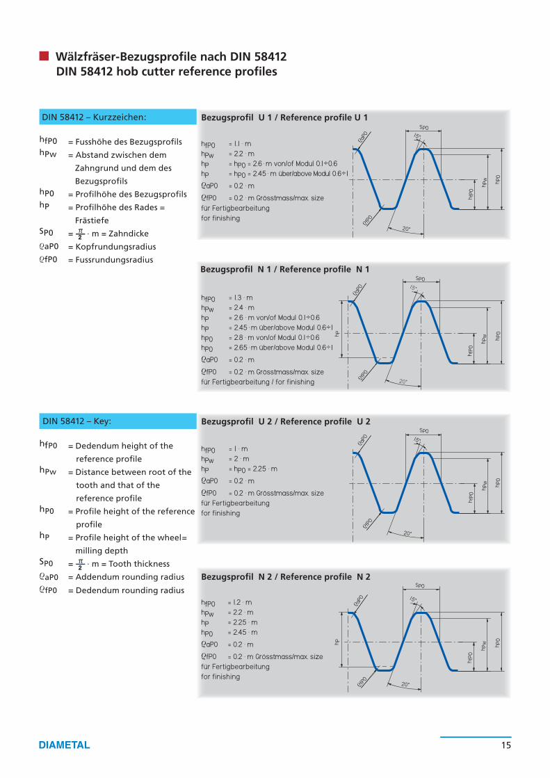
DIN 58412 – Kurzzeichen:
hfP0 = 1.1 · mhPw = 2.2 · mhP = hP0 = 2.6 · m von/of Modul 0.1÷0.6hP = hP0 = 2.45 · m über/above Modul 0.6÷1ρaP0 = 0.2 · mρfP0 = 0.2 · m Grösstmass/max. sizefür Fertigbearbeitungfor finishing
Bezugsprofil N 1 / Reference profile N 1
Bezugsprofil U 1 / Reference profile U 1
Bezugsprofil U 2 / Reference profile U 2
Bezugsprofil N 2 / Reference profile N 2
DIN 58412 – Key:
hfP0 = 1.3 · mhPw = 2.4 · mhP = 2.6 · m von/of Modul 0.1÷0.6hP = 2.45 · m über/above Modul 0.6÷1hP0 = 2.8 · m von/of Modul 0.1÷0.6hP0 = 2.65 · m über/above Modul 0.6÷1ρaP0 = 0.2 · mρfP0 = 0.2 · m Grösstmass/max. sizefür Fertigbearbeitung / for finishing
hfP0 = 1 · mhPw = 2 · mhP = hP0 = 2.25 · mρaP0 = 0.2 · mρfP0 = 0.2 · m Grösstmass/max. sizefür Fertigbearbeitungfor finishing
hfP0 = 1.2 · mhPw = 2.2 · mhP = 2.25 · mhP0 = 2.45 · mρaP0 = 0.2 · mρfP0 = 0.2 · m Grösstmass/max. sizefür Fertigbearbeitungfor finishing
Wälzfräser-Bezugsprofile nach DIN 58412DIN 58412 hob cutter reference profiles
hfP0 = Fusshöhe des BezugsprofilshPw = Abstand zwischen dem
Zahngrund und dem des
BezugsprofilshP0 = Profilhöhe des BezugsprofilshP = Profilhöhe des Rades =
FrästiefeSP0 = · m = ZahndickeρaP0 = KopfrundungsradiusρfP0 = Fussrundungsradius
² π
hfP0 = Dedendum height of the
reference profilehPw = Distance between root of the
tooth and that of the
reference profilehP0 = Profile height of the reference
profilehP = Profile height of the wheel=
milling depth SP0 = · m = Tooth thicknessρaP0 = Addendum rounding radiusρfP0 = Dedendum rounding radius
² π
q
20°
SPO
h PO
h fPO
h P
fPO
ρρ aP
O
SPO
h PO
h fPO
h P
fPO
ρρ aP
O
20°
q
SPO
h POh P
h aPO
20°
ρ aPO
ρ fPO
16 17
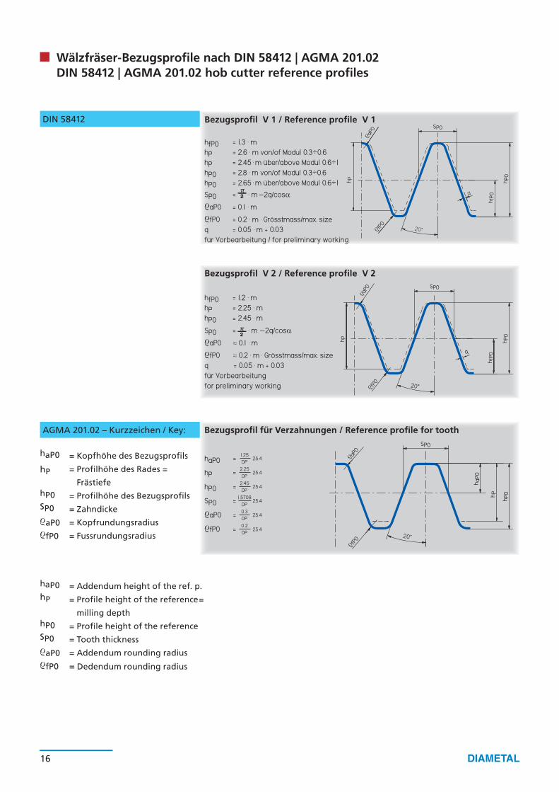
Wälzfräser-Bezugsprofile nach DIN 58412 | AGMA 201.02DIN 58412 | AGMA 201.02 hob cutter reference profiles
haP0 = Kopfhöhe des Bezugsprofils
hP = Profilhöhe des Rades =
FrästiefehP0 = Profilhöhe des BezugsprofilsSP0 = ZahndickeρaP0 = KopfrundungsradiusρfP0 = Fussrundungsradius
DIN 58412
Bezugsprofil V 2 / Reference profile V 2
Bezugsprofil V 1 / Reference profile V 1
Bezugsprofil für Verzahnungen / Reference profile for toothAGMA 201.02 – Kurzzeichen / Key:
haP0 = Addendum height of the ref. p.hP = Profile height of the reference=
milling depthhP0 = Profile height of the referenceSP0 = Tooth thicknessρaP0 = Addendum rounding radiusρfP0 = Dedendum rounding radius
hfP0 = 1.3 · mhP = 2.6 · m von/of Modul 0.3÷0.6hP = 2.45 · m über/above Modul 0.6÷1hP0 = 2.8 · m von/of Modul 0.3÷0.6hP0 = 2.65 · m über/above Modul 0.6÷1
SP0 = · m –2q/cosαρaP0 = 0.1 · m ρfP0 = 0.2 · m · Grösstmass/max. sizeq = 0.05 · m + 0.03 für Vorbearbeitung / for preliminary working
² π
haP0 =
hP =
hP0 =
SP0 =
ρaP0 =
ρfP0 =
1.25DP
25.4
2.25DP
25.4
2.45DP
25.4
1.5708DP
25.4
0.3DP
25.4
0.2DP
25.4
hfP0 = 1.2 · mhP = 2.25 · mhP0 = 2.45 · m
SP0 = · m –2q/cosαρaP0 ≈ 0.1 · mρfP0 ≈ 0.2 · m · Grösstmass/max. sizeq = 0.05 · m + 0.03für Vorbearbeitungfor preliminary working
² π
16 17
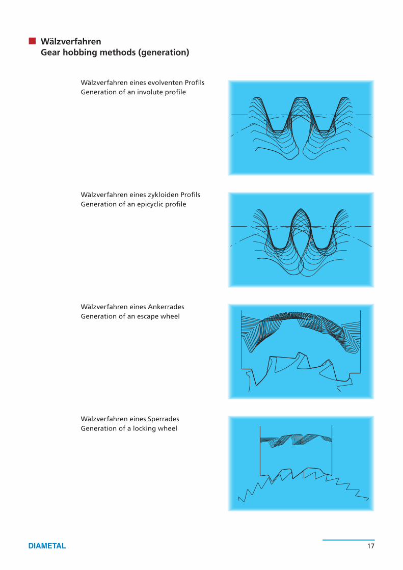
Wälzverfahren eines evolventen ProfilsGeneration of an involute profile
Wälzverfahren eines zykloiden ProfilsGeneration of an epicyclic profile
Wälzverfahren eines AnkerradesGeneration of an escape wheel
Wälzverfahren eines SperradesGeneration of a locking wheel
WälzverfahrenGear hobbing methods (generation)
18 19
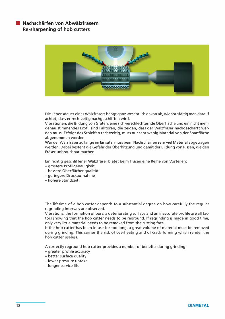
Nachschärfen von AbwälzfräsernRe-sharpening of hob cutters
Die Lebensdauer eines Wälzfräsers hängt ganz wesentlich davon ab, wie sorgfältig man darauf achtet, dass er rechtzeitig nachgeschliffen wird.Vibrationen, die Bildung von Graten, eine sich verschlechternde Oberfläche und ein nicht mehr genau stimmendes Profil sind Faktoren, die zeigen, dass der Wälzfräser nachgeschärft wer-den muss. Erfolgt das Schleifen rechtzeitig, muss nur sehr wenig Material von der Spanfläche abgenommen werden.War der Wälzfräser zu lange im Einsatz, muss beim Nachschärfen sehr viel Material abgetragen werden. Dabei besteht die Gefahr der Überhitzung und damit der Bildung von Rissen, die den Fräser unbrauchbar machen.
Ein richtig geschliffener Wälzfräser bietet beim Fräsen eine Reihe von Vorteilen: – grössere Profilgenauigkeit– bessere Oberflächenqualität– geringere Druckaufnahme– höhere Standzeit
The lifetime of a hob cutter depends to a substantial degree on how carefully the regular regrinding intervals are observed.Vibrations, the formation of burs, a deteriorating surface and an inaccurate profile are all fac-tors showing that the hob cutter needs to be reground. If regrinding is made in good time, only very little material needs to be removed from the cutting face.If the hob cutter has been in use for too long, a great volume of material must be removed during grinding. This carries the risk of overheating and of crack forming which render the hob cutter useless.
A correctly reground hob cutter provides a number of benefits during grinding:– greater profile accuracy– better surface quality– lower pressure uptake– longer service life
18 19
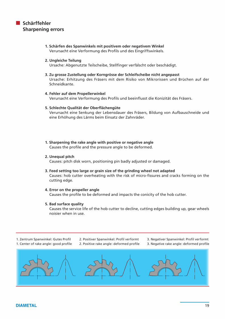
SchärffehlerSharpening errors
1. Schärfen des Spanwinkels mit positivem oder negativem WinkelVerursacht eine Verformung des Profils und des Eingriffswinkels.
2. Ungleiche TeilungUrsache: Abgenutzte Teilscheibe, Stellfinger verfälscht oder beschädigt.
3. Zu grosse Zustellung oder Korngrösse der Schleifscheibe nicht angepasstUrsache: Erhitzung des Fräsers mit dem Risiko von Mikrorissen und Brüchen auf der Schneidkante.
4. Fehler auf dem PropellerwinkelVerursacht eine Verformung des Profils und beeinflusst die Konizität des Fräsers.
5. Schlechte Qualität der OberflächengüteVerursacht eine Senkung der Lebensdauer des Fräsers, Bildung von Aufbauschneide und eine Erhöhung des Lärms beim Einsatz der Zahnräder.
1. Zentrum Spanwinkel: Gutes Profil1. Center of rake angle: good profile
2. Positiver Spanwinkel: Profil verformt2. Positive rake angle: deformed profile
3. Negativer Spanwinkel: Profil verformt3. Negative rake angle: deformed profile
1. Sharpening the rake angle with positive or negative angleCauses the profile and the pressure angle to be deformed.
2. Unequal pitchCauses: pitch disk worn, positioning pin badly adjusted or damaged.
3. Feed setting too large or grain size of the grinding wheel not adaptedCauses: hob cutter overheating with the risk of micro-fissures and cracks forming on the cutting edge.
4. Error on the propeller angleCauses the profile to be deformed and impacts the conicity of the hob cutter.
5. Bad surface qualityCauses the service life of the hob cutter to decline, cutting edges building up, gear wheels noisier when in use.
H
J
W
D
T20°
X
V°
20 21
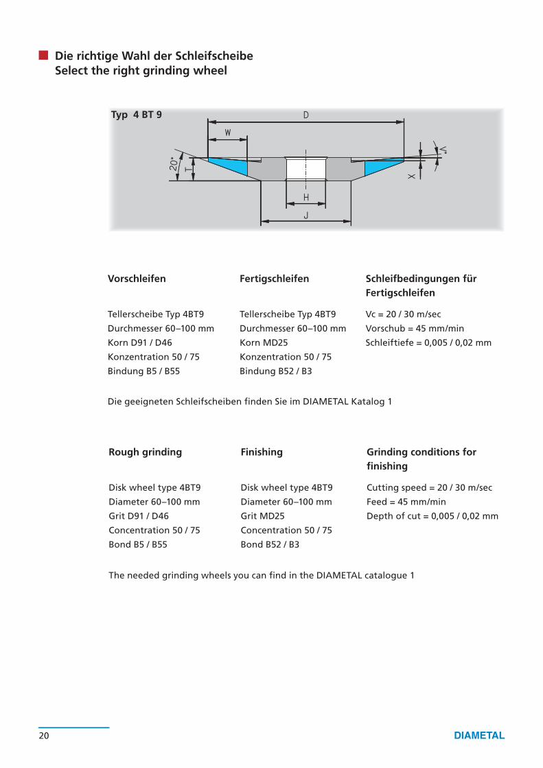
Die richtige Wahl der SchleifscheibeSelect the right grinding wheel
Typ 4 BT 9
Vorschleifen Fertigschleifen Schleifbedingungen fürFertigschleifen
Tellerscheibe Typ 4BT9 Tellerscheibe Typ 4BT9 Vc = 20 / 30 m/sec
Durchmesser 60–100 mm Durchmesser 60–100 mm Vorschub = 45 mm/min
Korn D91 / D46 Korn MD25 Schleiftiefe = 0,005 / 0,02 mm
Konzentration 50 / 75 Konzentration 50 / 75
Bindung B5 / B55 Bindung B52 / B3
Die geeigneten Schleifscheiben finden Sie im DIAMETAL Katalog 1
Rough grinding Finishing Grinding conditions forfinishing
Disk wheel type 4BT9 Disk wheel type 4BT9 Cutting speed = 20 / 30 m/sec
Diameter 60–100 mm Diameter 60–100 mm Feed = 45 mm/min
Grit D91 / D46 Grit MD25 Depth of cut = 0,005 / 0,02 mm
Concentration 50 / 75 Concentration 50 / 75
Bond B5 / B55 Bond B52 / B3
The needed grinding wheels you can find in the DIAMETAL catalogue 1

20 21
Erreichbare Oberflächengüte nach SchleifkorngrösseObtainable surface quality depending on grinding grit size
Hinweis:Beim Einsatz von Peripheriescheiben (Flach-, Aussenrund-, Innenrund-, Nutentiefschleifen etc.) muss zur Erreichung der in der Tabelle gezeigten Oberflächenwerte die Korngrösse 2 bis 3 Stufen feiner gewählt werden.
Note:When using periphery wheels (flat, external, internal, flute grinding, etc.) the grit size must be selected 2 to 3 grades finer to achieve the surface values shown in the table.
Diamant- und CBN-Scheibe, Kunstharzbindung, Topfscheibe-Kreuzschliff auf Hartmetall K20 / HSS 64 HRcDiamond and CBN wheel, resin bond, cup wheel, cross grinding on carbide metal K20/HSS 64HRc
FEPA-KorngrösseFEPA grit size
Mittlere Rauhtiefe RaMean roughness Ra
OberflächengüteSurface grade
SchleifvorgangGrinding operation
D CBN D CBN N
B 301 2.100 N8 SchruppenB 251 1.770 N8 Rough grindingB 213 1.410 N7B 181 1.120 N7B 151 0.750 N6B 126 0.660 N6
D 181 B 107 0.530 0.530 N6 GrobschleifenD 151 B 91 0.500 0.500 N6 Coarse grindingD 126 B 76 0.450 0.450 N6D 107 B 64 0.400 0.400 N5 VorschleifenD 91 B 54 0.330 0.330 N5 PregrindingD 76 B 46 0.250 0.250 N5 D 64 0.180 N4 FeinschleifenD 54 0.160 N4 Fine grindingD 46 0.150 N4MD 25 0.120 N3 FeinstschleifenMD 20 0.050 N2 Ultrafine grindigMD 10 0.025 N1
N1 N2 N3 N4 N5 N6 N7 N8
Ra (µm) 0.025 0.05 0.10 0.2 0.4 0.8 1.60 3.20Rt (µm) 0.500 0.80 1.25 2.5 5.0 8.0 16.0 32.0Rz (µm) 0.400 0.63 1.00 2.0 4.0 6.3 10.0 16.0
23
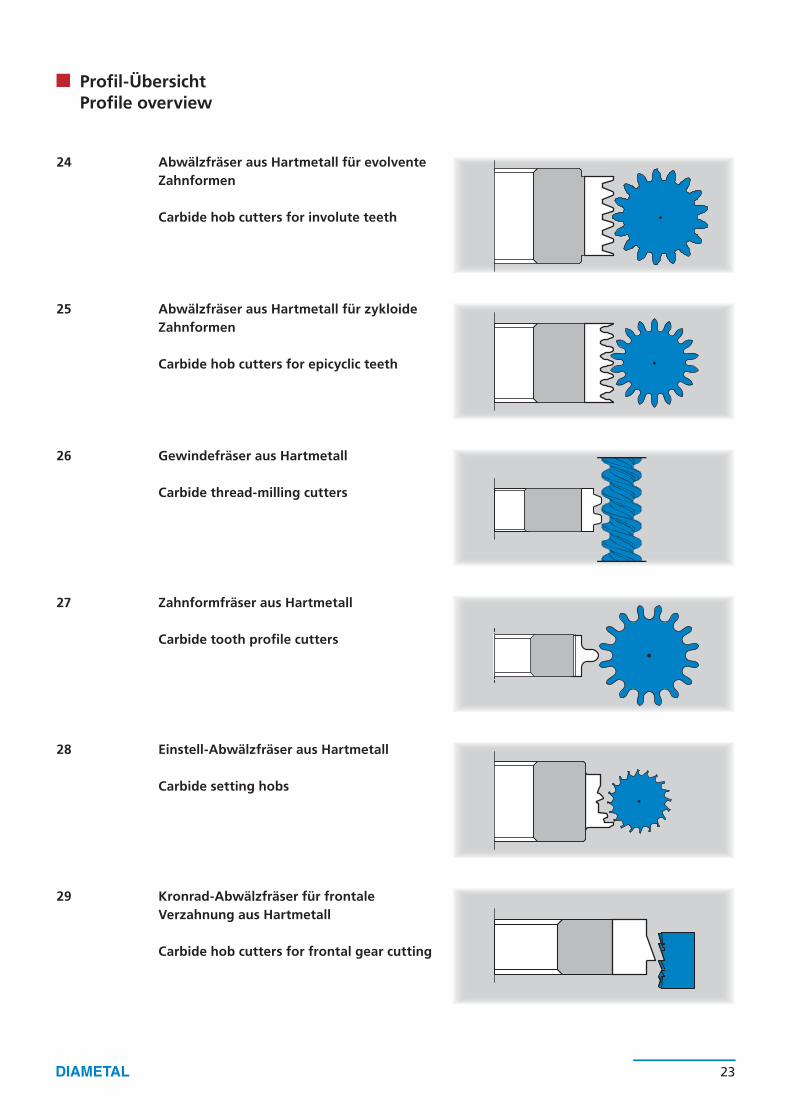
Profil-ÜbersichtProfile overview
Abwälzfräser aus Hartmetall für evolvente Zahnformen
Carbide hob cutters for involute teeth
Abwälzfräser aus Hartmetall für zykloide Zahnformen
Carbide hob cutters for epicyclic teeth
Gewindefräser aus Hartmetall
Carbide thread-milling cutters
Zahnformfräser aus Hartmetall
Carbide tooth profile cutters
Einstell-Abwälzfräser aus Hartmetall
Carbide setting hobs
Kronrad-Abwälzfräser für frontaleVerzahnung aus Hartmetall
Carbide hob cutters for frontal gear cutting
24
25
26
27
28
29
Fräser Breite Bohrung Zähnezahl ProfilhöheCutter Width Bore Number of teeth Height of profil
Ø D B Ø d H3 Z Max.
8 4 3.5 15 0.708 5|6 3.5 12 0.70
10 4 3.5 15 0.8510 5|6 3.5|4.5 12 0.8512 6|8 4.5|5|6 12|15 1.0016 6|8|10 8 12|15 1.3518 6|8|10|12 8 12|15 1.5524 6|8|10|12|16 8 12|15 2.0024 20|25|30|40 10 12|15 2.0032 20|25|30 10|13 12|15 2.6532 40|50 13 15 2.6540 20|25|30 16 15 4.0040 40|50|60 16 15 4.0050 50 22 15 4.7050 70 22 12 5.5060 70 22 12 7.00
24 25
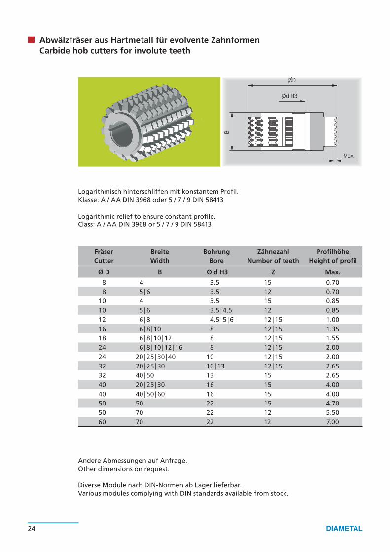
Abwälzfräser aus Hartmetall für evolvente ZahnformenCarbide hob cutters for involute teeth
Logarithmisch hinterschliffen mit konstantem Profil. Klasse: A / AA DIN 3968 oder 5 / 7 / 9 DIN 58413
Logarithmic relief to ensure constant profile. Class: A / AA DIN 3968 or 5 / 7 / 9 DIN 58413
Andere Abmessungen auf Anfrage. Other dimensions on request.
Diverse Module nach DIN-Normen ab Lager lieferbar. Various modules complying with DIN standards available from stock.
Fräser Breite Bohrung Zähnezahl ProfilhöheCutter Width Bore Number of teeth Height of profil
Ø D B Ø d H3 Z Max.
6 4|5|6 3.5 12 0.508 4 3.5 15 0.708 5|6 3.5 12 0.70
10 4|5|6 3.5 12 0.8510 6 4.5 12|15 0.8512 6 3.5 15 1.0012 6|8 4.5|5|6 12|15 1.0016 6|8|10 8 12|15 1.3518 6 6 12 1.5518 6|8|10|12 8 12|15 1.5524 6|8|10|12|16 8 12|15 2.0024 20|25|30|40 10 12|15 2.0032 20|25|30 10|13 15 2.65
24 25
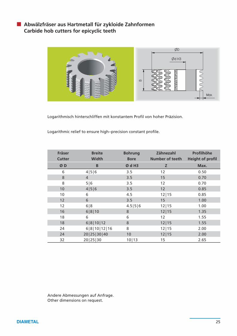
Abwälzfräser aus Hartmetall für zykloide Zahnformen Carbide hob cutters for epicyclic teeth
Logarithmisch hinterschliffen mit konstantem Profil von hoher Präzision.
Logarithmic relief to ensure high–precision constant profile.
Andere Abmessungen auf Anfrage. Other dimensions on request.

ØD
B
Max.
Fräser Breite Bohrung Zähnezahl ProfilhöheCutter Width Bore Number of teeth Height of profil
Ø D B Ø d H3 Z Max.
53 5|6|8 12|16 20 4.5053 5|6|8 12|16 30* 2.8063 6|8|10 12|16|22 20 5.0063 6|8|10 12|16|22 30* 3.5080 16|12 22 24 5.10
100 16 22 30 5.50
26 27
Gewindefräser aus Hartmetall Carbide thread-milling cutters
Präzisionfräser logarithmisch hinterschliffen mit konstantem Profil zum Fräsen von Schnecken und anderen Gewinden.
Precision cutters with logarithmic relief and with constant profile for cutting worms and other gears.
* Je nach Teilung und Profilhöhe* Depending on pitch and profile height
Andere Abmessungen auf Anfrage. Other dimensions on request.
ØD
Max.
B
Fräser Breite Bohrung Zähnezahl ProfilhöheCutter Width Bore Number of teeth Height of profil
Ø D B Ø d H3 Z Max.
8 2.0 3.5 12 0.7010 2.0 3.5|4.5 12 0.8012 2.0 3.5|4.5 12 1.0015 2.5 5 12 1.3516 3.0 5 12 1.3518 3.0 6 12 1.5524 3.0 8 12 2.00
26 27
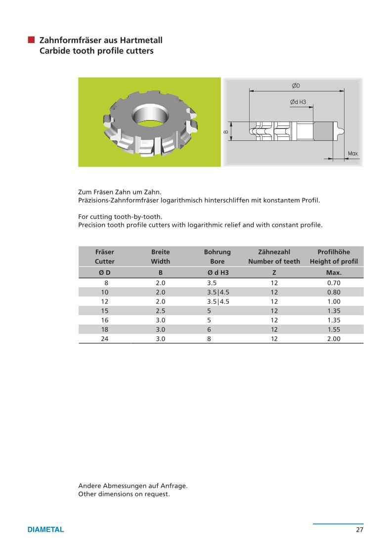
Zahnformfräser aus HartmetallCarbide tooth profile cutters
Zum Fräsen Zahn um Zahn.Präzisions-Zahnformfräser logarithmisch hinterschliffen mit konstantem Profil.
For cutting tooth-by-tooth.Precision tooth profile cutters with logarithmic relief and with constant profile.
Andere Abmessungen auf Anfrage. Other dimensions on request.

ØD
B
Max.
Fräser Breite Bohrung Zähnezahl ProfilhöheCutter Width Bore Number of teeth Height of profil
Ø D B Ø d H3 Z Max.
6 4|5|6 3.5 12 0.508 5|6 3.5 12 0.70
10 4|5|6 3.5|4.5 12 0.8512 6|8 4.5|5|6 12 1.1016 6|8|10 8 12 1.5018 6|8|10 8 12 1.5024 6|8|10 8 12 2.2532 20 10|13 12 2.65
28 29
Einstell-Abwälzfräser aus HartmetallCarbide setting hobs
Präzisions-Einstell-Abwälzfräser logarithmisch hinterschliffen für Ankerräder, Sternräder und andere asymmetrische Profile.
Precision setting hobs with logarithmic relief for escape wheels, star wheels and other asymmetrical profiles.
Die Fräserbreite ergibt sich je nach Profil.The hob widht results from the profile.
Andere Abmessungen auf Anfrage. Other dimensions on request.
ØD
B
Max.
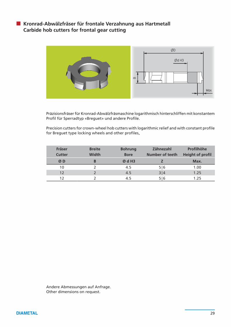
Fräser Breite Bohrung Zähnezahl ProfilhöheCutter Width Bore Number of teeth Height of profil
Ø D B Ø d H3 Z Max.
10 2 4.5 5|6 1.0012 2 4.5 3|4 1.2512 2 4.5 5|6 1.25
28 29
Kronrad-Abwälzfräser für frontale Verzahnung aus Hartmetall Carbide hob cutters for frontal gear cutting
Präzisionsfräser für Kronrad-Abwälzfräsmaschine logarithmisch hinterschliffen mit konstantem Profil für Sperradtyp «Breguet» und andere Profile.
Precision cutters for crown-wheel hob cutters with logarithmic relief and with constant profile for Breguet type locking wheels and other profiles.
Andere Abmessungen auf Anfrage. Other dimensions on request.
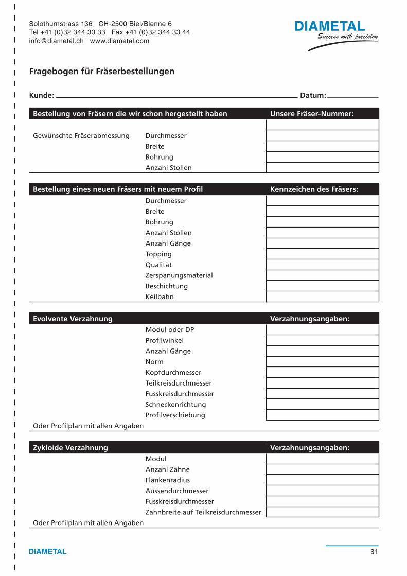
Bestellung von Fräsern die wir schon hergestellt haben Unsere Fräser-Nummer:
Gewünschte Fräserabmessung Durchmesser
Breite
Bohrung
Anzahl Stollen
Bestellung eines neuen Fräsers mit neuem Profil Kennzeichen des Fräsers:Durchmesser
Breite
Bohrung
Anzahl Stollen
Anzahl Gänge
Topping
Qualität
Zerspanungsmaterial
Beschichtung
Keilbahn
Evolvente Verzahnung Verzahnungsangaben:Modul oder DP
Profilwinkel
Anzahl Gänge
Norm
Kopfdurchmesser
Teilkreisdurchmesser
Fusskreisdurchmesser
Schneckenrichtung
Profilverschiebung
Oder Profilplan mit allen Angaben
Zykloide Verzahnung Verzahnungsangaben:Modul
Anzahl Zähne
Flankenradius
Aussendurchmesser
Fusskreisdurchmesser
Zahnbreite auf Teilkreisdurchmesser
Oder Profilplan mit allen Angaben
Fragebogen für Fräserbestellungen
Kunde: Datum:
31
Solothurnstrass 136 CH-2500 Biel/Bienne 6Tel +41 (0)32 344 33 33 Fax +41 (0)32 344 33 [email protected] www.diametal.com
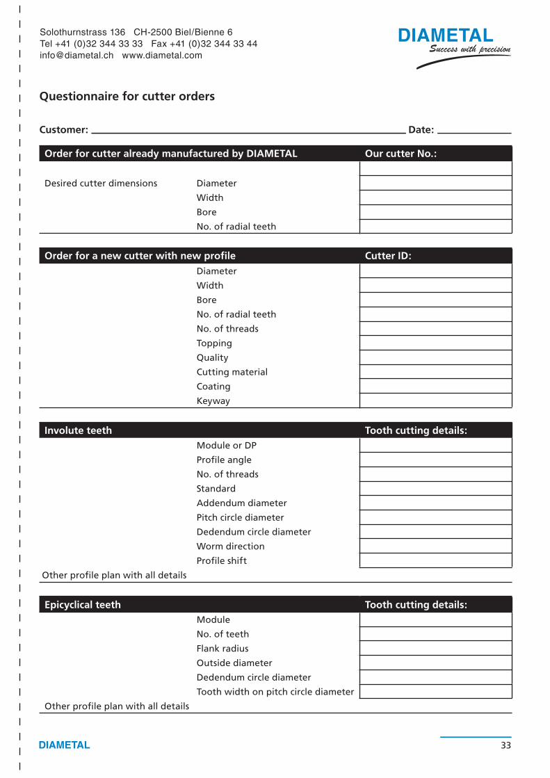
Order for cutter already manufactured by DIAMETAL Our cutter No.:
Desired cutter dimensions Diameter
Width
Bore
No. of radial teeth
Order for a new cutter with new profile Cutter ID:Diameter
Width
Bore
No. of radial teeth
No. of threads
Topping
Quality
Cutting material
Coating
Keyway
Involute teeth Tooth cutting details:Module or DP
Profile angle
No. of threads
Standard
Addendum diameter
Pitch circle diameter
Dedendum circle diameter
Worm direction
Profile shift
Other profile plan with all details
Epicyclical teeth Tooth cutting details: Module
No. of teeth
Flank radius
Outside diameter
Dedendum circle diameter
Tooth width on pitch circle diameter
Other profile plan with all details
Questionnaire for cutter orders
Customer: Date:
33
Solothurnstrass 136 CH-2500 Biel/Bienne 6Tel +41 (0)32 344 33 33 Fax +41 (0)32 344 33 [email protected] www.diametal.com
1
2
3
4
5
6
7
34
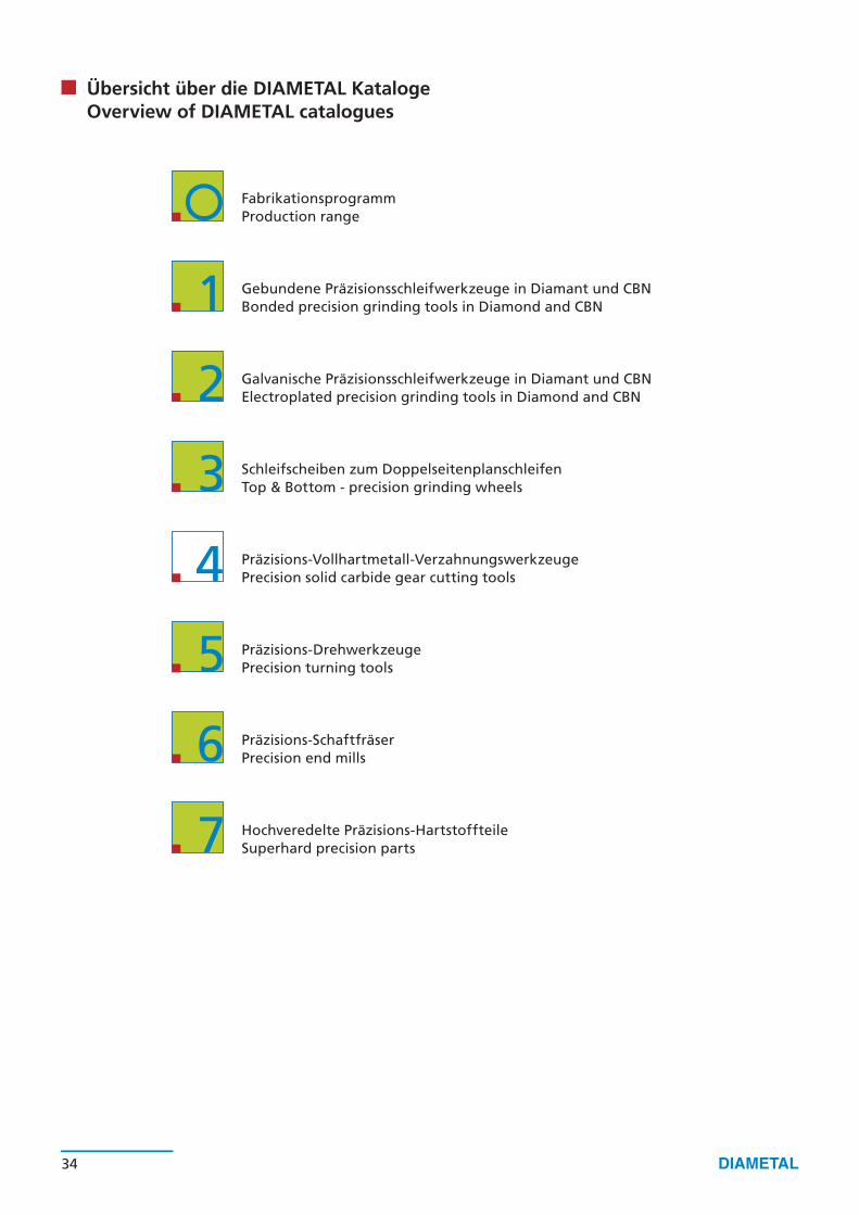
FabrikationsprogrammProduction range
Gebundene Präzisionsschleifwerkzeuge in Diamant und CBNBonded precision grinding tools in Diamond and CBN
Galvanische Präzisionsschleifwerkzeuge in Diamant und CBNElectroplated precision grinding tools in Diamond and CBN
Schleifscheiben zum Doppelseitenplanschleifen Top & Bottom - precision grinding wheels
Präzisions-Vollhartmetall-VerzahnungswerkzeugePrecision solid carbide gear cutting tools
Präzisions-DrehwerkzeugePrecision turning tools
Präzisions-SchaftfräserPrecision end mills
Hochveredelte Präzisions-HartstoffteileSuperhard precision parts
Übersicht über die DIAMETAL KatalogeOverview of DIAMETAL catalogues

DIAMETAL AG/SA
Solothurnstrasse 136 CH-2500 Biel/Bienne 6
Tel +41 (0)32 344 33 33 Fax +41 (0)32 344 33 44
[email protected] www.diametal.com
DIAMETAL France SA
Route de Wolschwiller F-68480 Oltingue
Tel +33 (0)3 89 07 58 00 Fax +33 (0)3 89 40 70 41
[email protected] www.diametal.com
DIAMETAL Italia S.R.L.
Via General Biancardi 9 I-21052 Busto Arsizio (VA)
Tel +39 (0)331 62 94 78 Fax +39 (0)331 62 97 20
[email protected] www.diametal.com
4 –
D|E
V
1.1
0
1|0
6
©D
IAM
ETA
L A
G