Embed Size (px)
Citation preview

P S-8R - POWER CONDIT IONER/SEqu EN C ER
Ow
ner
's M
an
ua
lPS-8RPOWER SEQUENCER, 15A

PS - 8R - POWER CONDIT IONER/SE qu EN C ER
descriptionThe PS-8R Power Sequencer is needed whenever various kinds of equipment must be powered up or down in groups, rather than all simultaneously. In au-dio systems, sequenced powering is often necessary to allow turn-on transients from low level amplifiers and processors to settle down before any power amps are turned on, because simultane-ous powering would result in a loud, annoying, and potentially destructive “pop” reaching the speakers. And in any large system whose com-ponents present an inductive load to the AC line (including electric motors, power supplies, and power amplifiers of all kinds), sequenced powering can avoid excessive inrush currents that cause circuit breakers to trip even though the steady-state currents are not excessive.
power sequencing featuresusing the PS-8R is a simple and inexpen-sive way to apply and remove power in a con-trolled, repeatable, foolproof 3-step sequence. It is ideal when large installations must be switched by inexperienced personnel.
The PS-8R provides three outlet pairs labeled Delay 1, Delay 2, and Delay 3, that receive power ap-proximately 1/2, 5, and 10 seconds, respectively, after the front panel switch is switched to “ON.” When switched to “OFF,” the sequence is reversed, with Delay 3 losing power after approximately 1/2 second, Delay 2 after 5 seconds, and Delay 1 after 10 seconds. See the rear panel illustration on page 3. The turn-on delay intervals are factory preset at these durations, but may be altered by means of an internal trimpot adjustment (see “Adjusting the Delay Intervals” for details). In addition to the
featuresPower-up in three delayed outlet groups•
Power-down reverses sequence•
Triple-mode varistor spike • and surge suppression
RFI / EMI filtering with multi-stage filter•
Power Status LED’s indicate which • outlet groups have power
Mains Wiring indicators moni-• tor wiring integrity, show Nor-mal and five kinds of faults
Rated 15 amps•
Remote option allows turn-on and • turn-off at a distance simply by con-necting a momentary or maintained-contact switch (and LED if desired)
Multiple units may be linked to • handle higher currents and/or more than three delay groups
Three pairs of switched out-• lets on rear panel
Three unswitched outlets • (one front, two rear)
Circuit breaker•
Ten foot heavy duty A.C. cord•
Three year limited warranty•
Congratulations on your purchase of a Furman PS-8R Power Sequencer, a well-designed, reliable, and simple to use product that will help you avoid many headaches involved in installing a rack full of complex equipment.
1

P S-8R - POWER CONDIT IONER/SEqu EN C ER
delayed outlets, a single front panel outlet and a rear panel pair are unswitched. Power is available at the unswitched outlets regardless of the posi-tion of the front panel (or remote) switch. All rear panel outlets are standard 120V, 15A duplex types.
In the event of a power outage, of course all equipment plugged into a PS-8R will lose power simultaneously. However, when power is restored, the delayed outlet groups will again turn on in the usual delayed sequence.
We recommend that power amps receive power last — plug them all into Delay 3 or divide them into two groups and plug one group into Delay 2 and the other into Delay 3. Low level equipment such as mixers and signal processors should use Delay 1.
Equipment incorporating clocks or timers such as VCR’s, or equipment that must respond to wireless remote actuation should use the unswitched outlets. We suggest keeping the front panel unswitched outlet free for equipment that is only in use temporarily.
The overall capacity of the PS-8R is 15 amps. This refers to the combined steady-state current drawn by all devices plugged into all of its nine outlets. If this combined current level exceeds 15 amps at any time, the circuit breaker will trip, cutting off power to your rack. If this occurs, you must reduce the load by unplugging one or more units from the PS-8R. Then push the button on the circuit breaker (on the rear panel) down and in to reset it.
Although 15 amps is an absolute limit, the PS-8R’s power sequencing capability will allow you to come as close as possible to using the full 15 amps, because the risk of tripping the breaker is greatly reduced. This is because the PS-8R handles large but temporary inrush currents in stages, rather than simultaneously, allow-ing each stage to settle to its steady-state cur-rent draw before the next stage is powered.
Power Conditioning FeaturesThe PS-8R offers all basic power conditioning fea-tures besides its sequencing capability. It provides varistor spike and surge protection across all three
modes (line to neutral, line to ground, and neutral to ground), responding in nanoseconds to clamp excessive transient voltages to safe levels. There is also a sophisticated multi-stage filter for blocking radio frequency line noise. The filter works to prevent noise from fluorescent lights, certain dimmers, radio transmitters, and similar sources of “electronic pol-lution” leaking from the AC line into sensitive audio, video, or computer circuits. Clean, filtered power is provided at all 9 outlets, even the unswitched ones.
Despite its many protective features, you should be aware that the PS-8R does not compensate if the AC line voltage itself is high or low (i.e., it does not com-pensate for brownout conditions). If you frequently move your rack to different locations, derive power from generators, use long extension cords, travel internationally, or are in an area particularly prone to brownouts, you may benefit from the use of one of Furman’s AC Line Voltage Regulators in addition to the PS-8R. If you do use a voltage regulator, run the raw power line into the regulator first so that the PS-8R receives a stabilized voltage to distribute.
Mains wiring Fault analyzerThe PS-8R also assists in analyzing any faults that may occur in the AC mains wiring. Two green and one red neon indicators light in a specific pattern for normal wiring and in different patterns for various faults. When the AC wiring is correct, both green indicators will be lit, but not the red indicator. If any other pattern of indicators is lit, a fault is present. The chart next to the indicators identifies its exact nature. Since any wiring fault presents a potentially serious safety hazard, the assistance of a qualified electri-cian should be obtained in correcting the problem.
adjusting the delay intervalThe delay interval (the time between the turn-on or turn-off of outlets 1 and 2, or 2 and 3 — not 1 and 3) is factory preset at approximately 5 seconds. It is possible to lengthen or shorten the delay interval by making an internal adjustment to the PS-8R. How-ever, due to the risk of electric shock, this procedure should only be done by a qualified technician.
unplug the PS-8R and remove its top cover by unscrewing the four top panel screws and one
2

PS - 8R - POWER CONDIT IONER/SE qu EN C ER
front panel screw that secure it. The delay adjust-ment is Trimpot VR1, located on the printed circuit board near the front left corner. It is the only trimpot on the board. It is equipped with a thumbwheel for easy adjustment. The range of adjustment of the delay interval is from a minimum of about 1 second to a maximum of about 7 seconds.
reMote switcHingIn the most basic configuration, only two wires and an SPST switch are needed to initiate remote ON or OFF sequence. The switch may be either a momentary or maintained-contact type. If a third & fourth wire are used, an LED may also be installed at the remote end to indicate that the power is on.
Maintained vs. MoMentary ContaCt switChingMaintained switches, such as most toggle switches and push-on/push-off switches (includ-ing the Furman RS-1), stay open until switched and then remain closed until switched again.
Momentary switches, usually pushbutton types like the Furman RS-2, are normally open and stay closed only as long as the button is pressed. An on-off switch of either kind may be used to actuate the PS-8R’s remote operation.
Maintained switches are generally most con-venient when there is only one remote loca-tion. When more than one switch location is required, momentary switches allow the se-quence to be started from different locations.
PS-8R main circuit board has 5 pairs of ter-minals (PCB REV F and later) labeled as:
JMP1 (REM TO +12V = OFF), when the REM and +12V terminals are tied to-gether, the PS-8R will sequence OFF.
JMP2 (MOMENTARY), when the REM and +12V terminals are momentary tied together, the PS-8R will sequence ON or OFF.
JMP3 (REM TO +12V = ON), when the REM and +12V terminals are tied to-gether, the PS-8R will sequence ON.
JMP4 (REM TO GND = ON), when the REM and GND terminals are tied to-gether, the PS-8R will sequence ON (Note: JMP1 must have a jumper installed).
JMP5, spare jumper holder.
The PS-8R unit comes factory-set for maintained operation (jumper is installed on JMP1). It may be easily converted to other operations by moving jumper plug/plugs on the PS-8R’s circuit board.
to do this:
1. Disconnect the unit from AC power.
3

P S-8R - POWER CONDIT IONER/SEqu EN C ER
2. Remove the four top cover screws and one front panel screw that secure the top cover.
3. In the rear left corner of the circuit board you will find the 5 pairs of terminals men-tioned above. Install the jumper plug on the terminal for the mode of operation desired.
4. Reattach the top cover.
Maintained ModeThere are three maintained modes of operation:
reM to +12V = off (jumper installed on JMp1)
Connection of the REM terminal to the +12V terminal initiates an OFF sequence. Disconnecting initiates an ON sequence. If the cable run is long, it is recommended that the REM wire be tied to the PS-8R’s GND terminal during ON operation rather than leave it floating. This will require the use of a third conductor and a double-throw switch.
reM to +12V = on (jumper plug installed on JMp3)
OFF sequence.
NOTE: In Maintained Mode, DO NOT USE the “START ON-OFF SEquENCE” switch on the front panel. Doing so may activate an unintended sequence. If a Furman RS-1 is the controlling switch, contact Furman’s Tech Support department for the proper wiring diagrams.
MoMentary Mode (JuMper plug installed on JMp2).
The PS-8R has “memory” - it only needs a momentary signal from the remote switch to change its state from ON to OFF or OFF to ON.
JMP
REM TO +12V = OFF
MOMENTARY MODE
REM TO +12V = ON
REM TO GND = ON
1 2 3 4
JUMPER SETTING CHART
4
CLASS 1WIRING
+12V
STATUS
REM
GND
OPTIONAL STATUS LED
OFF
ON
Connection of the REM terminal to the +12V terminal initiates an ON sequence. Disconnecting initiates an OFF sequence. If the cable run is long, it is recommended that the REM wire be tied to the PS-8R’s GND terminal during OFF operation rather than leave it floating.
reM to gnd = on (jumper plugs installed on JMp1 and JMp4)
Connection of the REM terminal to the GND terminal initiates an ON sequence. Disconnecting initiates an
When first plugged in (or after power is lost and reapplied) the “memory” state is OFF. This means the unit will be OFF even if the front panel on/off rocker switch is ON. It will stay off until sequenced on by a momentary connection of the REM terminal to +12V terminal. The sequence starts on the rising edge of the signal.
The front panel START ON-OFF SEquENCE switch is in parallel with, and functionally equivalent to, one or more remote momentary switches connected to the barrier strip in the rear.
CLASS 1WIRING
+12V
STATUS
REM
GND
OPTIONAL STATUS LED
PS - 8R - POWER CONDIT IONER/SE qu EN C ER
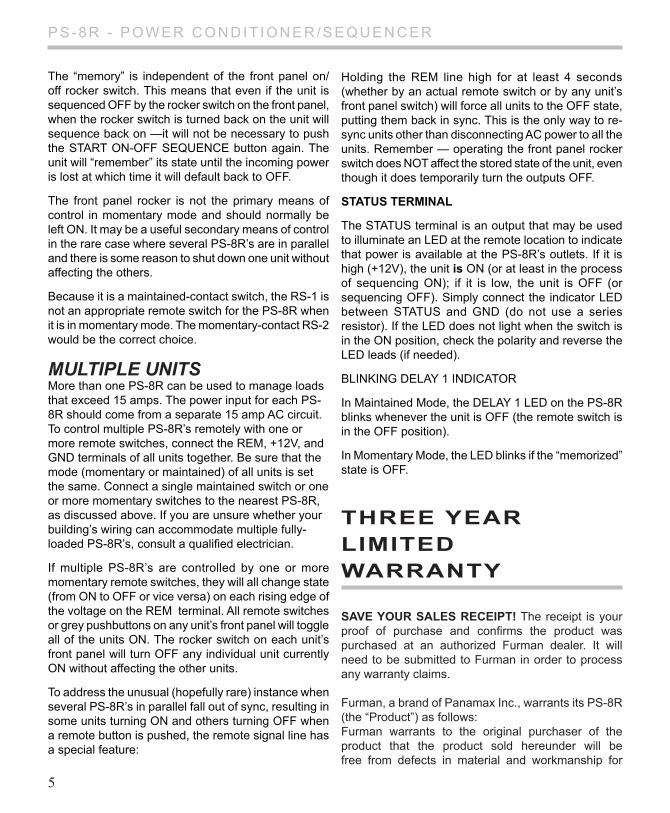
The “memory” is independent of the front panel on/off rocker switch. This means that even if the unit is sequenced OFF by the rocker switch on the front panel, when the rocker switch is turned back on the unit will sequence back on —it will not be necessary to push the START ON-OFF SEquENCE button again. The unit will “remember” its state until the incoming power is lost at which time it will default back to OFF.
The front panel rocker is not the primary means of control in momentary mode and should normally be left ON. It may be a useful secondary means of control in the rare case where several PS-8R’s are in parallel and there is some reason to shut down one unit without affecting the others.
Because it is a maintained-contact switch, the RS-1 is not an appropriate remote switch for the PS-8R when it is in momentary mode. The momentary-contact RS-2 would be the correct choice.
MultiPle unitsMore than one PS-8R can be used to manage loads that exceed 15 amps. The power input for each PS-8R should come from a separate 15 amp AC circuit. To control multiple PS-8R’s remotely with one or more remote switches, connect the REM, +12V, and GND terminals of all units together. Be sure that the mode (momentary or maintained) of all units is set the same. Connect a single maintained switch or one or more momentary switches to the nearest PS-8R, as discussed above. If you are unsure whether your building’s wiring can accommodate multiple fully-loaded PS-8R’s, consult a qualified electrician.
If multiple PS-8R’s are controlled by one or more momentary remote switches, they will all change state (from ON to OFF or vice versa) on each rising edge of the voltage on the REM terminal. All remote switches or grey pushbuttons on any unit’s front panel will toggle all of the units ON. The rocker switch on each unit’s front panel will turn OFF any individual unit currently ON without affecting the other units.
To address the unusual (hopefully rare) instance when several PS-8R’s in parallel fall out of sync, resulting in some units turning ON and others turning OFF when a remote button is pushed, the remote signal line has a special feature:
Holding the REM line high for at least 4 seconds (whether by an actual remote switch or by any unit’s front panel switch) will force all units to the OFF state, putting them back in sync. This is the only way to re-sync units other than disconnecting AC power to all the units. Remember — operating the front panel rocker switch does NOT affect the stored state of the unit, even though it does temporarily turn the outputs OFF.
status terMinal
The STATuS terminal is an output that may be used to illuminate an LED at the remote location to indicate that power is available at the PS-8R’s outlets. If it is high (+12V), the unit is ON (or at least in the process of sequencing ON); if it is low, the unit is OFF (or sequencing OFF). Simply connect the indicator LED between STATuS and GND (do not use a series resistor). If the LED does not light when the switch is in the ON position, check the polarity and reverse the LED leads (if needed).
BLINkING DELAY 1 INDICATOR
In Maintained Mode, the DELAY 1 LED on the PS-8R blinks whenever the unit is OFF (the remote switch is in the OFF position).
In Momentary Mode, the LED blinks if the “memorized” state is OFF.
tHree year liMited warranty
saVe your sales receipt! The receipt is your proof of purchase and confirms the product was purchased at an authorized Furman dealer. It will need to be submitted to Furman in order to process any warranty claims.
Furman, a brand of Panamax Inc., warrants its PS-8R (the “Product”) as follows:Furman warrants to the original purchaser of the product that the product sold hereunder will be free from defects in material and workmanship for
5

P S-8R - POWER CONDIT IONER/SEqu EN C ER
a period of three years from the date of purchase. If the product does not conform to this Limited Warranty during the warranty period (as herein above specified), purchaser shall notify Furman of the claimed defects by calling 707-763-1010 or via email ([email protected]). If the defects are of such type and nature as to be covered by this warranty, Furman shall authorize purchaser to return the product to Furman headquarters. Warranty claims MuST be accompanied by a copy of the original purchase invoice or receipt showing the purchase date. Shipping charges to Furman headquarters must be prepaid by the purchaser of the product. Furman shall, at its own expense, furnish a replacement product or, at Furman’s option, repair the defective product. Return shipping charges back to purchaser will be paid by Furman.
tHe foregoing is in lieu of all otHer warranties, eXpress or iMplied, including But not liMited to tHe iMplied warranties of MercHantaBility and fitness for a particular purpose.
Furman does not warrant against damages or defects arising out of improper use or abnormal handling of the product, or against defects or damages arising from improper installation. This warranty shall be cancelable by Furman at its sole discretion if the product is modified in any way without written authorization from Furman or Panamax Inc. This warranty also does not apply to products upon which repairs have been affected or attempted by persons other than pursuant to written authorization by Furman or Panamax Inc.
tHis warranty is eXclusiVe. The sole and exclusive obligation of Furman shall be to repair or replace the defective product in the manner and for the period provided above. Furman shall not have any other obligation with respect to the products or any part thereof, whether based on contract, tort, strict liability or otherwise. under no circumstances, whether based on this Limited Warranty or otherwise, shall Furman be liable for incidental, special, or consequential damages. This Limited Warranty states the entire obligation of Furman with respect to the product. If any part of this Limited Warranty is
6
determined to be void or illegal, the remainder shall remain in full force and effect.

PS - 8R - POWER CONDIT IONER/SE qu EN C ER
Maximum load: PS-8R: 15 amps (1800 watts at 120 VAC) Input Voltage Range: PS-8R: 85 to 135 VAC;Mains Wiring Analyzer: Detects 1 normal mode and 5 fault modesDelay Interval: 5 seconds (adjustable with internal trimpot)Remote Switch: Momentary or maintained action.Remote Terminal: Screw terminals or Eurostyle pluggable Terminal Block, 2 for switch, 2 additional for optional LED (22 ga. wiring minimum).Spike Protection Modes: Line to neutral, neutral to ground, line to groundSpike Clamping Voltage: PS-8R: TVSS rating 400V peak, L-N, N-G, L-G (tested to UL 1449)Response Time: 1 nanosecondMaximum Surge Current: 6,500 amps (8 x 20 ms pulse)
ps-8r specifications
LISTED
PS-REL AC Relay
MP
15A, 20A, 30A
RS-1 and RS-2
Remote System
related productsThe PS-8R, along with other Furman AC power accessories, can be an integral part of a complete AC power control system.
Maximum Spike Energy: 80 joules per mode, 240 joules total protectionNoise Attenuation: Transverse and common modes: 20 dB at 200 kHz, rising to >40 dB, 1 to 100 MHzMechanical: Dimensions: 1.75” H x 19” W x 8” D. Weight: 6 lbs (2.7 kg). Construction: Steel chassis, zinc chromate plating; .125” brushed and black anodized aluminum front panel; 3 oz. copper double-sided glass epoxy printed circuit board Power Consumption: Switch off: 6 watts Switch on: 8.5 wattsSafety Agency Approvals: cTUVus listed.
Furman Sound, LLC.1690 Corporate Circle Petaluma, California 94954-6919 uSA
Phone: 707-763-1010 Fax: 707-763-1310 Web: www.furmansound.com E-mail: [email protected]
serVice
questions or issues with your Furman unit should be directed to the Furman Customer Service Department, available 8AM-4:30PM Pacific Time at (707) 763-1010 or via email at [email protected]. If a unit requires service, it must have an RA number assigned from Furman’s Customer Service Department.
Before returning any equipment for repair, please be sure that it is adequately packed and cushioned against damage in shipment, and that it is insured. We suggest that you save the original packaging and use it to ship the product for servicing. Also, please enclose a brief note giving your name, address, phone number and a description of the problem. Please display your RA number prominently on the front of all packages.


![Sequencer 1, Sequencer 2 or Drum - Arturiadownloads.arturia.com/products/beatstep-pro/manual/BeatStepPro... · —Sequencer 1, Sequencer 2 or Drum SHIFT + [>>] = Extend sequence SHIFT](https://img.pdfslide.net/doc/110x75/5adbc3047f8b9add658e5b6e/sequencer-1-sequencer-2-or-drum-sequencer-1-sequencer-2-or-drum-shift-.jpg)