Embed Size (px)
Citation preview

System: Brakes
ABS: Antilock Brake Rotors and Pads Brake System Basics Disc Brakes Drum Brakes Hydraulics Master Cylinder, Brake fluid, Bleeding Parking Brakes Power-assisted Brakes
ABS: Antilock Brake Systems
If the brakes are applied too hard when driving on slippery road surfaces, they may lock up or stop the wheel. The wheel then loses frictional contact with the road and skids and the vehicle is no longer under control. Experienced drivers know that the way to prevent lock-up is to pump the brake pedal up and down rapidly.
Many late-model cars are now equipped with an antilock brake system (ABS). The antilock brake system does the same thing as an experienced driver. It senses that a wheel is about to lock-up or skid and it rapidly interrupts the braking pressure to the brake system at that wheel.
The basic parts of a typical antilock braking system are shown below.
The brains behind the antilock brake system is the computer, which monitors system operation at all times. It processes information from the wheel sensors and determines wheel speed. From this information, the electronic controller can determine whether one wheel is turning slower than the other wheels.

The computer gets its information on wheel speeds from wheel sensors located on each wheel. Each sensor assembly consists of a magnetic pickup sensor and a toothed sensor ring. The front sensor rings are attached to the back side of the rotor assembly.
The rear sensor rings are attached to the axle shaft. The pickup assemblies are bolted to brackets at each wheel.
The wheel sensors are essentially magnetic pickup assemblies. Each pickup assembly consists of a permanent magnet with a coil of wire wound around it. The sensor is positioned extremely close to the sensor ring, which rotates as the wheel turns. As the teeth pass the pickup assembly, the signal is induced in the coil by electromagnetic induction as the magnetic field goes from strong to weak and back to strong. This signal change is used by the computer to determine wheel speed.

The antilock brake system uses a hydraulic control unit in place of the standard master
cylinder. The hydraulic control unit consists of a master cylinder, a vacuum or hydraulic booster, electric pump, accumulator, a solenoid valve body assembly, and pressure control and warning switches.
The electric pump is a high pressure pump designed to run at frequent intervals for short periods of time. The pump fills the hydraulic accumulator and supplies high pressure brake fluid to the brake system.
The accumulator is a nitrogen gas-filled assembly used to store and supply pressure to the
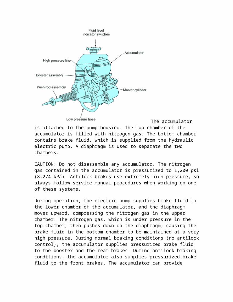
brake system. The accumulator is attached to the pump housing. The top chamber of the accumulator is
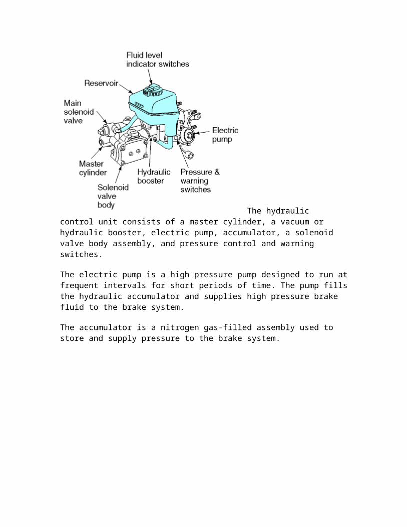
filled with nitrogen gas. The bottom chamber contains brake fluid, which is supplied from the hydraulic electric pump. A diaphragm is used to separate the two chambers.
CAUTION: Do not disassemble any accumulator. The nitrogen gas contained in the accumulator is pressurized to 1,200 psi (8,274 kPa). Antilock brakes use extremely high pressure, so always follow service manual procedures when working on one of these systems.
During operation, the electric pump supplies brake fluid to the lower chamber of the accumulator, and the diaphragm moves upward, compressing the nitrogen gas in the upper chamber. The nitrogen gas, which is under pressure in the top chamber, then pushes down on the diaphragm, causing the brake fluid in the bottom chamber to be maintained at a very high pressure. During normal braking conditions (no antilock control), the accumulator supplies pressurized brake fluid to the booster and the rear brakes. During antilock braking conditions, the accumulator also supplies pressurized brake fluid to the front brakes. The accumulator can provide pressure required for a number of stops if the electric pump should fail.
The solenoid valve assembly is a set of electrically operated solenoid switching valves.
The main solenoid valve opens a connection between the boost pressure chamber of the brake power booster and the internal master cylinder reservoir and closes the flow to the reservoir during antilock control. This provides a continuous supply of high pressure brake fluid during antilock control to replace the fluid being allowed back to the reservoir. When antilock control stops, the main valve closes and the return to the reservoir is reopened. By closing the main valve, accumulator pressure is removed from the front brake circuits within the master cylinder.
A set of smaller solenoid valves is located in a solenoid valve body. The valve body contains three pairs of electrically operated solenoid valves: a pair for each of the front brakes and a pair that controls both back brakes together. Each pair contains a normally
open inlet solenoid valve and a normally closed outlet solenoid valve. During normal braking conditions (no antilock control), brake pressure is supplied to the brakes through the inlet solenoid valves upon brake application.
The computer determines the rotation speed of each wheel. If it senses a possible wheel lock-up, it goes into the antilock function and then applies voltage to the appropriate solenoid valves. When the system goes into antilock control, the computer will open and close the appropriate inlet and outlet solenoid valves, which control the operation of any of the brakes on any of the four wheels and prevent wheel lock-up. When the system is in antilock brake operation, the brake pedal will pulsate at an extremely fast rate. Pressure control and warning switches warn the driver of any malfunction in the system.
Brake Rotors and Pads
Disc brakes are used on the front wheels of most cars and on all four wheels on many cars. A disc rotor is attached to the wheel hub and rotates with the tire and wheel. When the driver applies the brakes, hydraulic pressure from the master cylinder is used to push friction linings against the rotor to stop it. A simplified illustration of a disk brake is
shown below.

A disc brake rotor assembly is shown below.
The rotor is usually made of cast iron. The hub may be manufactured as one piece with the rotor or in two parts. The rotor has a machined braking surface on each face. A splash shield, mounted to the steering knuckle, protects the rotor from road splash.
A rotor may be solid or ventilated. Operation of the master cylinder if there is a rear system failure. Ventilated designs have cooling fins cast between the braking surfaces. This construction considerably increases the cooling area of the rotor casting. Also, when the wheel is in motion, the rotation of these fan-type fins in the rotor provides increased air circulation and more efficient cooling of the brake. Disc brakes do not fade even after rapid, hard brake applications because of the rapid cooling of the rotor.
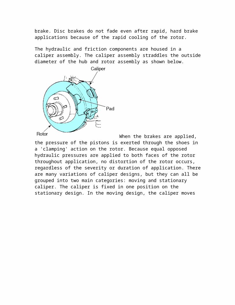
The hydraulic and friction components are housed in a caliper assembly. The caliper assembly straddles the outside diameter of the hub and rotor assembly as shown below.
When the brakes are applied, the pressure of the pistons is exerted through the shoes in a 'clamping' action on the rotor. Because equal opposed hydraulic pressures are applied to both faces of the rotor throughout application, no distortion of the rotor occurs, regardless of the severity or duration of application. There are many variations of caliper designs, but they can all be grouped into two main categories: moving and stationary caliper. The caliper is fixed in one position on the

stationary design. In the moving design, the caliper moves in relation to the rotor.
The caliper cylinder bore contains a piston and seal. The seal has a rectangular cross section. It is located in a groove that is machined in the cylinder bore. The seal fits around the outside diameter of the piston and provides a hydraulic seal between the piston and the cylinder wall. The rectangular seal provides automatic adjustment of clearance between the rotor and shoe and linings following each application. When the brakes are applied, the caliper seal is deflected by the hydraulic pressure and its inside diameter rides with the piston within the limits of its retention in the cylinder groove. When hydraulic pressure is released, the seal relaxes and returns to its original rectangular shape, retracting the piston into the cylinder enough to provide proper
running clearance. As brake linings wear, piston travel tends to exceed the limit of deflection of the seal; the piston therefore slides in the seal to the precise extent necessary to compensate for lining wear.

The top of the piston bore is machined to accept a sealing dust boot. The piston in many calipers is steel, precision ground, and nickel chrome plated, giving it a very hard and durable surface. Some manufacturers are using a plastic piston. This is much lighter than steel and provides for a much lighter brake system. The plastic piston insulates well and prevents heat from transferring to the brake fluid. Each caliper contains two shoe and lining assemblies. They are constructed of a stamped metal shoe with the lining riveted or bonded to the shoe and are mounted in the caliper on either side of the rotor. One shoe and lining assembly is called the inboard lining because it fits nearest to the center line of the car. The other is called the outboard shoe and lining assembly.
As already mentioned, the caliper is free to float on its two mounting pins or bolts. Typical mounting pins are shown in the exploded view of the floating caliper.
Teflon sleeves in the caliper allow it to move easily on the pins. During application of the brakes, the fluid pressure behind the piston increases. Pressure is exerted equally against the bottom of the piston and the bottom of the cylinder bore. The pressure applied to the piston is transmitted to the inboard shoe and lining, forcing the lining against the inboard rotor surface. The pressure applied to the bottom of the cylinder bore forces the caliper to move on the mounting bolts toward the inboard side, or toward the car.

Because the caliper is one piece, this movement causes the outboard section of the caliper to apply pressure against the back of the outboard shoe and lining assembly, forcing the lining against the outboard rotor surface. As the line pressure builds up, the shoe and lining assemblies are pressed against the rotor surfaces with increased force, bringing the car to a stop.
The application and release of the brake pressure actually causes a very slight movement of the piston and caliper. Upon release of the braking effort, the piston and caliper merely relax into a released position. In the released position, the shoes do not retract very far from the rotor surfaces.
As the brake lining wears, the piston moves out of the caliper bore and the caliper repositions itself on the mounting bolts an equal distance toward the car. This way, the caliper assembly maintains the inboard and outboard shoe and lining in the same relationship with the rotor surface throughout the full length of the lining.
The stationary or fixed caliper has a hydraulic piston on each side of the rotor as shown
below. Larger calipers may have two pistons on each side of the rotor. The inboard and outboard brake shoes are pushed against the rotor by their own pistons. The caliper is anchored solidly and does not move.

The seals around the pistons work just like those already described. The main disadvantage of the stationary caliper is that it has more hydraulic components. This means they are more expensive and have more parts to wear out.
Brake System Basics
Braking action begins when the driver pushes on the brake pedal. The brake pedal is a lever, pivoted at one end, with the master cylinder push rod attached to the pedal near the pivot point. With this lever arrangement, the force applied to the master cylinder piston through the push rod is multiplied several times over the force applied at the brake pedal.

A pedal assembly is usually mounted to a brake support bracket as shown below.
The bracket is mounted to the inside of the engine compartment cowl or firewall. The master cylinder push rod that connects the pedal linkage to the master cylinder goes through a hole in the firewall.
The master cylinder is mounted on the opposite side of the firewall in the engine
compartment. . If the car has manual brakes, the cylinder will be mounted directly to the firewall. If a power booster is used, it will be mounted to the firewall and the cylinder is mounted to the booster.

Disc Brakes
Disc brakes are used on the front wheels of most cars and on all four wheels on many cars. A disc rotor is attached to the wheel hub and rotates with the tire and wheel. When the driver applies the brakes, hydraulic pressure from the master cylinder is used to push friction linings against the rotor to stop it. A simplified illustration of a disk brake is
shown below.
A disc brake rotor assembly is shown below.
The rotor is usually made of cast iron. The hub may be manufactured as one piece with the rotor or in two parts. The rotor has a machined braking surface on each face. A splash shield, mounted to the steering knuckle, protects the rotor from road splash.
A rotor may be solid or ventilated. Operation of the master cylinder if there is a rear system failure. Ventilated designs have cooling fins cast between the braking surfaces. This construction considerably increases the cooling area of the rotor casting. Also, when the wheel is in motion, the rotation of these fan-type fins in the rotor provides increased

air circulation and more efficient cooling of the brake. Disc brakes do not fade even after rapid, hard brake applications because of the rapid cooling of the rotor.
The hydraulic and friction components are housed in a caliper assembly. The caliper assembly straddles the outside diameter of the hub and rotor assembly as shown below.
When the brakes are applied, the pressure of the pistons is exerted through the shoes in a 'clamping' action on the rotor. Because equal opposed hydraulic pressures are applied to both faces of the rotor throughout application, no distortion of the rotor occurs, regardless of the severity or duration of application. There are many variations of caliper designs, but they can all be grouped into two main categories: moving and stationary caliper. The caliper is fixed in one position on the stationary design. In the moving design, the caliper moves in relation to the rotor.
Most late-model cars use the moving caliper design. This design uses a single hydraulic piston and a caliper that can float or slide during application. Floating designs 'float' or move on pins or bolts. In sliding designs, the caliper slides sideways on machined surfaces. Both designs work in basically the same way.

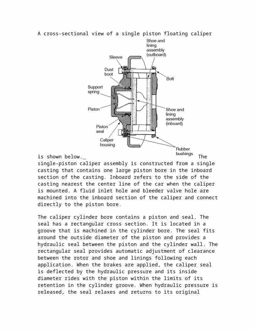
A cross-sectional view of a single piston floating caliper is shown below.
The single-piston caliper assembly is constructed from a single casting that contains one large piston bore in the inboard section of the casting. Inboard refers to the side of the casting nearest the center line of the car when the caliper is mounted. A fluid inlet hole and bleeder valve hole are machined into the inboard section of the caliper and connect directly to the piston bore.
The caliper cylinder bore contains a piston and seal. The seal has a rectangular cross section. It is located in a groove that is machined in the cylinder bore. The seal fits around the outside diameter of the piston and provides a hydraulic seal between the piston and the cylinder wall. The rectangular seal provides automatic adjustment of clearance between the rotor and shoe and linings following each application. When the brakes are applied, the caliper seal is deflected by the hydraulic pressure and its inside diameter rides with the piston within the limits of its retention in the cylinder groove. When hydraulic pressure is released, the seal relaxes and returns to its original rectangular shape, retracting the piston into the cylinder enough to provide proper

running clearance. As brake linings wear, piston travel tends to exceed the limit of deflection of the seal; the piston therefore slides in the seal to the precise extent necessary to compensate for lining wear.
The top of the piston bore is machined to accept a sealing dust boot. The piston in many calipers is steel, precision ground, and nickel chrome plated, giving it a very hard and durable surface. Some manufacturers are using a plastic piston. This is much lighter than steel and provides for a much lighter brake system. The plastic piston insulates well and prevents heat from transferring to the brake fluid. Each caliper contains two shoe and lining assemblies. They are constructed of a stamped metal shoe with the lining riveted or bonded to the shoe and are mounted in the caliper on either side of the rotor. One shoe and lining assembly is called the inboard lining because it fits nearest to the center line of the car. The other is called the outboard shoe and lining assembly.
As already mentioned, the caliper is free to float on its two mounting pins or bolts. Typical mounting pins are shown in the exploded view of the floating caliper.

Teflon sleeves in the caliper allow it to move easily on the pins. During application of the brakes, the fluid pressure behind the piston increases. Pressure is exerted equally against the bottom of the piston and the bottom of the cylinder bore. The pressure applied to the piston is transmitted to the inboard shoe and lining, forcing the lining against the inboard rotor surface. The pressure applied to the bottom of the cylinder bore forces the caliper to move on the mounting bolts toward the inboard side, or toward the car.
Because the caliper is one piece, this movement causes the outboard section of the caliper to apply pressure against the back of the outboard shoe and lining assembly, forcing the lining against the outboard rotor surface. As the line pressure builds up, the shoe and lining assemblies are pressed against the rotor surfaces with increased force, bringing the car to a stop.
The application and release of the brake pressure actually causes a very slight movement of the piston and caliper. Upon release of the braking effort, the piston and caliper merely relax into a released position. In the released position, the shoes do not retract very far from the rotor surfaces.
As the brake lining wears, the piston moves out of the caliper bore and the caliper repositions itself on the mounting bolts an equal distance toward the car. This way, the caliper assembly maintains the inboard and outboard shoe and lining in the same relationship with the rotor surface throughout the full length of the lining.
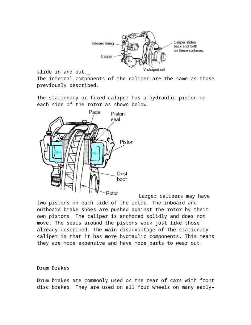
Sliding calipers are made to slide back and forth on the steering knuckle support to which it is mounted. There is a V shaped surface, sometimes called a rail, on the caliper that matches a similar surface on the steering knuckle support. These two mating surfaces allow the caliper to slide in and out.
The internal components of the caliper are the same as those previously described.
The stationary or fixed caliper has a hydraulic piston on each side of the rotor as shown
below. Larger calipers may have two pistons on each side of the rotor. The inboard and outboard brake shoes are pushed against the rotor by their own pistons. The caliper is anchored solidly and does not move. The seals around the pistons work just like those already described. The main disadvantage of the stationary caliper is that it has more hydraulic components. This means they are more expensive and have more parts to wear out.
Drum Brakes
Drum brakes are commonly used on the rear of cars with front disc brakes. They are used on all four wheels on many early-model cars. The drum brake stops a rotating drum and wheel through friction between an anchored brake shoe and the revolving drum.

. The energy of motion of the vehicle is converted into heat that is dissipated by the brake drum and related parts.
The parts of a rear wheel brake drum assembly are shown in the exploded view below.
Each
brake unit consists of a backing plate, a primary and secondary brake shoe, brake shoe retaining pins and springs, return springs, a parking brake cable and linkage, automatic adjuster components, an adjuster screw assembly, a hydraulic wheel cylinder, and a brake drum.
The brake components are mounted on the backing plate, which is bolted directly to the rear axle housing flange, or to the front steering knuckle. An anchor pin mounted at the top or bottom of the backing plate works as the brake shoe locating member and pivot point.
The primary brake shoe is installed in the leading position facing the front of the automobile. The secondary brake shoe is installed in the trailing position facing the rear of the automobile. The brake shoes are identified by their respective lining thickness and length. In many designs, the primary brake shoe lining is thinner and slightly shorter than the secondary shoe lining.
Each brake shoe is attached to the backing plate by a retaining pin, hold-down spring, and pin retainers. The lower ends of the brake shoes are fitted to the backing plate anchor pin and are held in position by the brake shoe return spring. The upper ends of the brake shoes fit into the wheel cylinder pistons and are held together by the shoe-to-shoe spring. The parking brake lever, strut, and strut-to-shoe spring are attached to the top of the two brake shoes. The automatic adjuster components are mounted on the secondary brake shoe. When brakes are applied, hydraulic pressure from the master cylinder is applied to the wheel cylinder pistons. The hydraulic pressure against the pistons forces the brake shoes against the brake drum. When the brake pedal is released, the shoe return springs pull the brake shoes back to the released position.
A cross-sectional view of a wheel cylinder is shown below.
The cylinder is made from cast iron or aluminum. Two aluminum pistons are positioned at either end of the cylinder bore. Two rubber cups, separated by a spacing spring, seal the hydraulic pressure.

When the brakes are applied, fluid enters the center of the wheel cylinder. The pressure is sealed by the rubber cups. As the pressure builds up, the pistons are forced outward. Linkage from the pistons is used to push the brake shoes in contact with the drums. When the brakes are released, the brake shoe retracting springs force the pistons back into their bores.
A rubber boot at each end of the cylinder prevents dirt from entering. A bleeder valve is located in the cylinder to bleed out air. An exploded view of a wheel cylinder is shown
below.
Brake shoes are the parts that support the brake lining. The lining is either riveted or bonded to the face or table of the shoe. The face is formed to fit the contour of the drum. The force used to push the brake shoes against the drum is created by the applied force of the wheel cylinder and the movement of the shoe within the drum.
The movement of the shoes within the drum is used to help apply the brakes. We call this the self-energized or brake servo action. To understand how self-energized brakes work, consider that a brake shoe that is free to move within the brake drum would start to move with the drum when brought into contact with it unless it were held in some manner. There would be no braking action because there would be no resistance to cause friction. The brake shoe has to be held to keep it from turning with the rotation of the brake drum.

The anchor pin on the brake backing plate keeps the shoe from turning with the drum. The frictional force tries to turn the shoe around the anchor pin. As a result, the shoe is pulled tighter against the drum with a force greater than the applied force that first moved the shoe against the drum. This is called self-energized action.
When two shoes are connected by an adjusting link with some type of an anchor pin at the top, the applied force acts on one shoe, moving it into drum rotation and energizing the shoe through the action of the drum. Because this shoe starts the movement, we call it the primary shoe; the other shoe is called the secondary shoe.
The greater pressure or force applied to the secondary shoe is again increased by the action of the drum if the shoe pivots on the anchor. Therefore, the braking efficiency of the secondary shoe is greater than that of the primary shoe through self-energized action. The action of both shoes has a tendency to force them tighter into the drum as they are both energized by drum rotation as shown below.
Drum brakes have an automatic adjuster. The automatic adjuster mechanism maintains correct operating clearance between the brake lining and brake drum by adjusting the brake shoes in direct proportion to lining wear.
The shoes are linked together opposite the anchor by an adjuster screw assembly and a spring. The adjuster holds them apart. The spring holds them against the adjuster ends. A wheel with teeth, called the star wheel, is used to manually or automatically turn the

adjuster screw assembly. Making the adjuster screw assembly longer by unscrewing it brings the shoes in closer contact with the drums. The adjuster spring bears against the star wheel teeth, providing a ratchet lock. A slot in the backing plate gives access to the star wheel.
The cable-operated self-adjuster shown below is a popular style of adjusting mechanism.
An adjuster lever is connected to the secondary brake shoe at one end and engages the teeth of the star adjuster at the other end. A cable is attached to the adjusting lever at one end and runs up through a cable guide to connect to the anchor. An adjuster spring is attached to the lever and works against the action of the cable.
As the brake shoes wear, they move further away from their anchor because the thinner lining allows more movement. When the lining wears enough to require adjustment, the secondary shoe will pull on the adjuster cable. The cable will, in turn, pull on the adjuster lever. The lever pivots on the secondary shoe and moves into engagement with the next slot on the star adjuster wheel. The star wheel turns the adjuster assembly in a direction to lengthen it and position the shoes closer to the drum. Because the adjuster lever is attached to the secondary shoe, it works when the secondary shoe moves away from its anchor. This can occur only if the brakes are applied when the car is backing up. In the forward direction, the primary shoe is the one that moves away from its anchor. So, self-adjusting occurs when the driver backs up the car and puts the brakes on.
Hydraulic Lines and Valves
Hydraulic lines made of tubes and hoses are used to transmit fluid under pressure between the master cylinder and each of the wheel brake units.
Several valves may be used in the system. A warning light pressure switch is used on all brake systems. A combination valve is used on some front disc brake-equipped cars to improve brake balance between the front disc brakes and rear drum brakes. A stop light switch is used to signal other drivers during a stop.
Hydraulic tubes are used to direct fluid between stationary brake parts. Most hydraulic tubes used in the brake system are doublewall, welded steel tubes, coated to resist rust. The tube ends are double flared or have a chamber-type flare to guard against leakage. Threaded fittings are used to connect the tubes to brake parts.
The wheel brake units move up and down with the suspension. The master cylinder and steel brake tubes are mounted to the stationary body and frame. Flexible hoses are used to connect stationary brake components with moving components. Hoses must be able to withstand high fluid pressures without expansion and must be free to flex during spring

deflection and wheel turns without damaging the hose. Hoses come in different sizes and lengths, with a variety of end fittings to accommodate different vehicle requirements.
Some typical hoses are shown here.
The stop light switch is a spring-loaded electrical switch installed in the vehicle's stop light circuit. In some installations, the switch is operated by hydraulic pressure. In others, the switch is mechanically operated through contact with the brake pedal. With the brakes released, the circuit through the switch is open. When brakes are applied, the switch closes to complete the circuit to the stop lights. A typical mechanical stop light switch is
shown here.
Most late-model cars use a combination switch that contains a warning light switch, a metering valve, and a proportioning valve. The warning light switch is designed to light a brake warning lamp on the instrument panel if there is a hydraulic failure in either side of the split system. The switch works by sensing a pressure difference between two hydraulic circuits.

A cross-sectional view of a typical combination switch is shown here.
The switch body has connections for the hydraulic lines from the master cylinder. Outlet connections go to the two separate systems. This can be the front and rear wheels. On the diagonal style, a left front and right rear is paired together. The right front and left rear are separate systems.
A small switch piston is positioned between the two hydraulic systems. A spring positions the switch piston in the center of the switch. When the pressure is equal in both the front and rear hydraulic systems, the switch piston remains centered and does not contact the switch terminal in the bore of the switch.
If pressure fails in one of the hydraulic systems, hydraulic pressure moves the piston toward the inoperative side. The piston moves off-center to push up a switch pin. The switch pin activates the contacts inside the electrical terminal. This provides a ground for the warning lamp circuit and lights the warning lamp.
Most cars that use front disc brakes and rear drum brakes use a metering and proportioning valve in the system to achieve balanced braking between the front and rear wheels. The purpose of the metering valve is to improve braking balance, particularly during light brake application.
The metering valve keeps the front discs from operating until the rear drums have started to work. The valve is needed because disc brakes are fast acting; drum brakes have spring tensions and play in linkages to overcome first. The valve is located in the line to the front brakes. It works on fluid pressure and is normally closed. When the brake pedal is depressed, the fluid flows first to the rear brakes. As they begin to take hold, the system pressure builds up enough to open the metering valve, admitting pressure to the front brakes. Once open, the valve has no effect. The effect of the metering valve is felt during the beginning stages of all brake applications and throughout the duration of light brake

applications. The proportioning valve is installed in the hydraulic circuit going to the rear drum brakes. Its function is to maintain the correct proportion between line pressures to the front and rear brakes and, therefore, provide a balanced vehicle braking system.
The proportioning valve reduces the hydraulic pressure at the rear drum brakes when high pressure is required at the front disc brakes. The valve helps to prevent premature rear wheel lock-up and skidding during heavy brake applications and provides better braking balance.
Master Cylinder Parts and Operation
The master cylinder is a type of hydraulic pump operated by the driver through the pedal and push rod. A simplified illustration of how the master cylinder works is shown below.
The master cylinder push rod is connected to a piston inside the cylinder. There is hydraulic fluid in front of the piston.
When the pedal is depressed, the master cylinder piston is pushed forward. The fluid in the master cylinder and the entire system, being incompressible, transmits the force exerted by the master cylinder piston to all the inner surfaces of the system. At this point, only the pistons in the wheel cylinders or caliper are free to move, and because the hydraulic fluid is not compressible, the pistons move outward to force the brake shoes against the brake drums or rotors.
There are two basic advantages of using a hydraulic system to operate the brakes. First, fluid lines are easy to route from the master cylinder to each of the wheel brake units. Second, hydraulics allow us to multiply the force used to apply the brake shoes. When you use a hydraulic jack to lift a car, you are multiplying your effort using the principles of hydraulics. This multiplying effect is done using the principles of pressure and force.

Pressure can be defined as the amount of force applied to a specific area. Suppose a hydraulic pressure of 10 psi (pounds per square inch) were applied to an object with a
surface area of 16 square inches. The total applied force would equal 160 pounds (10 psi pressure times an area of 16 square inches). If the same 10 PSI were applied to an object with a surface area of 2 square inches, a force of 20 pounds would be applied. The relative size of the master cylinder piston and the pistons used at the wheel brake units allow the driver's brake pedal effort to be multiplied hydraulically.
Master Cylinder Construction and Operation

The master cylinder is constructed of two main parts: a reservoir and a master cylinder
body. The reservoir provides a supply of brake fluid for cylinder operation. All current reservoirs are split designs. This means they provide two separate storage areas for two separate piston assemblies. The split design allows for separating the front and rear, or one front and one rear system, from each other in case of hydraulic failure.
The reservoir may be cast as one piece with the cylinder body or it may be a separate plastic container. All reservoirs have a removable cover or caps so that brake fluid can be added to the system. A flexible rubber diaphragm at the top of the master cylinder reservoir seals the hydraulic system from possible entrance of contamination while permitting expansion or contraction of the fluid within the reservoirs without direct venting. There are two holes, or ports, at the bottom of each reservoir section. One is called the replenishing port, the other a vent port. These ports permit passage of fluid between each pressure chamber and its fluid reservoir during certain operating conditions.
The exploded view of the master cylinder with a one-piece reservoir shows the parts of the master cylinder body.

The body is a long aluminum or cast iron cylinder positioned under the reservoir. Inside the cylinder are two spool-shaped pistons. The pistons are fitted with rubber seals used to prevent fluid from leaking around the pistons. One piston is called the primary, the other the secondary. Each piston provides a separate hydraulic system for the front and rear brakes or on the diagonal system between one set of front and rear brakes. Springs in the cylinder return the pistons into position after braking. Two outlet holes provide the connection for the hydraulic lines. A snap ring holds the components inside the cylinder and a boot fits around the rear of the cylinder and push rod to prevent dirt from entering the cylinder.
The operation of the primary and secondary piston is the same. We examine how one piston works when the brakes are applied. When the brake pedal is depressed, force is transferred through the push rod to the master cylinder piston, which moves forward. After the primary seal covers the replenishing port, the master cylinder chamber is closed to the reservoir so that further piston travel builds up pressure. Fluid is then forced through the outlet into the lines leading to the wheel cylinders. Hydraulic pressure behind the wheel cylinder cup forces the pistons outward, causing the brakes to be applied as

shown below. When the brakes are released, return springs in the drum brake mechanisms pull the shoes away from the drums. This movement pushes the wheel cylinder pistons inward, forcing fluid back through the lines to the master cylinder. However, the master cylinder piston returns to the released position faster than fluid can fill the chamber, thus creating a momentary vacuum. To compensate for the vacuum, fluid flows from the reservoir, through the vent port, through the vent holes in the piston, and around the primary seal as shown below.
The dual master cylinder operates in the same manner as the single unit just described, except that it provides two independent systems, one for the front brakes and one for the rear, or one for each diagonal set of front and rear brakes. Under normal conditions, when the brakes are applied, the primary piston moves forward. At the same time, a combination of hydraulic pressure and the force of the primary piston spring moves the secondary piston forward. When the pistons have moved forward so that their primary

seals cover the replenishing ports, hydraulic pressure is built up and transmitted to the
front and the rear wheels. .
In case of a hydraulic failure in the rear brake system, the primary piston will move forward when the brakes are applied, but will not build up hydraulic pressure. Only a small force is transferred to the secondary piston through the primary piston spring until the piston extension screw comes in contact with the secondary piston. Then, push rod force is transmitted directly to the secondary piston and enough pressure is built up to
operate the front brakes.
If there is a hydraulic failure in the front brake system, both pistons will move forward when the brakes are applied, just like normal. Due to the front system failure, however, there is nothing to resist secondary piston travel except the secondary piston spring. This permits the primary piston to build up only negligible pressure until the secondary piston

bottoms in the cylinder bore. Then, enough hydraulic pressure will be built up to operate
the rear brakes.
Brake Master Cylinder Fluids
The brake system uses hydraulic power generated by a master cylinder to activate the four wheel brake assemblies. A fluid reservoir is located on top of the master cylinder. The fluid level in the brake master cylinder must be checked regularly at intervals
specified by the manufacturer.
Brake fluid is a specially formulated liquid that must meet Society of Automotive Engineers and federal standards. These specifications list the necessary qualities of a brake fluid. The following are the most important:
Must flow freely at low and high temperatures. Must have a high boiling point (over 400F). Must not deteriorate metal or rubber brake parts. Must lubricate metal and rubber parts. Must be able to absorb moisture that enters the hydraulic system.

Brake fluid is rated by the Department of Transportation (DOT). The brake fluid is then assigned a number. The common ratings are DOT 3, DOT 4, and DOT 5. The higher the number, the higher the fluid's boiling point. The DOT rating is found on the can of brake fluid. The shop and owner's manual specify what rating is correct for the car. Do not use a brake with a lower DOT rating than specified by the manufacturer. The lower rated fluid could boil and cause a loss of brake effectiveness.
Most brake fluid is glycol based. The word 'glycol' is usually not shown on the front of the container. The word 'silicone' is shown next to the name of the brake fluid if it has a silicone base. Always use the correct type of fluid specified in the shop or owner's manual. Do not mix the types of fluids. If you use the incorrect type of fluid you might cause a loss of brake efficiency.
WARNING: Brake fluid must always be stored in clean, dry containers. Brake fluid is hygroscopic; that is, it will attract moisture and must be kept away from dampness in a tightly sealed container. When water enters brake fluid, it causes its boiling point to lower. Fluid should be protected from contamination, especially oil, grease, or other petroleum products. Never reuse brake fluid.
CAUTION: Never use gasoline, kerosene, motor oil, transmission fluid, or any fluid containing mineral oil to clean brake system components. These fluids will cause the rubber cups and seals in the master or caliper units to soften, swell, and distort, resulting in brake system failure.
Parking Brakes
The parking brake assembly is designed to apply the brakes mechanically to prevent the car from rolling when parked, or to stop the car in the event of a complete hydraulic failure. Most parking brakes operate on the two rear brakes. Some vehicles with front wheel drive have front wheel parking brakes. In these cases, in an emergency stop, most of the stopping power would be required on the front of the car.
The parking brake may be activated by a hand lever or a foot pedal. In either style, pushing the pedal or pulling the lever causes a cable connected to the rear brakes to be

pulled. The cable has an equalizer so that the cable pulls the same amount on both left and right rear brakes.
The parts of the drum brake parking brake system are shown below.
The parking brake lever is connected to the secondary brake shoe. The lever is mounted on the back of the shoe and is connected to it by a pivot pin located in the upper end of the lever. The pivot pin is retained in the shoe by a washer and clip. The parking brake cable is attached to the lower end of the lever. A strut, located below the lever pivot pin, connects the lever to the primary brake shoe. The strut is notched at each end and is fitted into

accommodating notches in the lever and primary brake shoe. An oval-shaped spring, installed on the primary shoe end of the strut, is used to position the strut.
When the parking brake is applied, the cable pulls the lower end of the parking brake lever forward, causing the connecting strut to push the primary brake shoe forward. At the same time, the upper end of the lever pushes the secondary brake shoe rearward. The combined action of the lever and strut expands the brake shoes, forcing them against the
drum to develop brake action.
Power-assisted Brakes
A power-assist brake system is used on most cars to reduce the braking effort required by the driver. There are two general types of power-assist brakes. The most common type uses an intake manifold vacuum acting on a diaphragm to provide the power assist. The other type uses hydraulic power developed by a pump to provide the assist. The vacuum power-assist brake uses a large diaphragm in a canister behind the master cylinder as

shown below. The canister is connected by a hose to the engine intake manifold as shown below.
The push rod connected from the brake pedal goes through the power-assist unit on its way to the master cylinder. Inside

the canister is a large diaphragm. This diaphragm is connected to the push rod. Engine intake manifold vacuum is applied to both sides of the diaphragm. When the brakes are applied, valving inside the canister is operated by the push rod. Atmospheric pressure is admitted to one side of the diaphragm. With vacuum on one side and atmospheric pressure on the other, the diaphragm moves toward the master cylinder. Because the push rod is connected to the diaphragm, it also moves. The large diaphragm has enough force to take much of the effort of applying the brakes away from the driver.
Hydraulic boosters require a hydraulic pump to provide the power assist. In many systems, the power steering pump is used to provide power for both the power steering and power brakes. As shown below, fluid under pressure goes from the power steering pump to a hydraulic boost unit behind the master cylinder

. This unit contains a power piston and valving. When the brakes are applied, hydraulic pressure pushes on the boost piston, which in turn pushes on the brake push rod. The hydraulic power takes much of the effort out of brake application.
A typical hydraulic boost system is shown below.
The hydraulic booster normally has an accumulator, which is a device that is spring loaded or charged with pressurized gas. This device provides emergency pressure to apply the brakes should the power steering flow be interrupted for any reason. The system is good for one to three stops, depending on the type of accumulator. Dash warning lights indicate when the system has failed.

CAUTION: Accumulators are under very high pressure. Never disassemble an accumulator without specific instructions to do so in a shop service manual. Incorrect disassembly procedures could cause the accumulator to fly apart and injure you.