Embed Size (px)
Citation preview
PS1 / PS2 Series Pressure Controls
Technical Data
PS12_35037_EN_R05.doc 1 / 12 11.04.2006
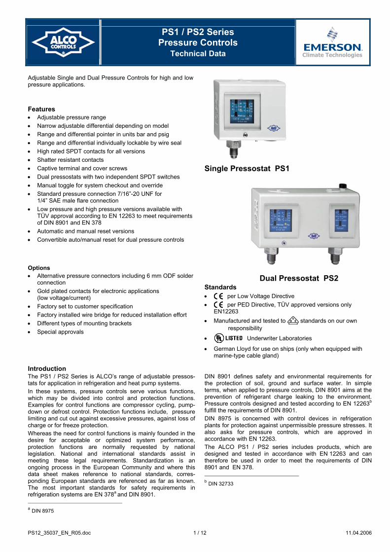
Adjustable Single and Dual Pressure Controls for high and low pressure applications.
Features • Adjustable pressure range • Narrow adjustable differential depending on model • Range and differential pointer in units bar and psig • Range and differential individually lockable by wire seal • High rated SPDT contacts for all versions • Shatter resistant contacts • Captive terminal and cover screws • Dual pressostats with two independent SPDT switches • Manual toggle for system checkout and override • Standard pressure connection 7/16”-20 UNF for
1/4” SAE male flare connection • Low pressure and high pressure versions available with
TÜV approval according to EN 12263 to meet requirements of DIN 8901 and EN 378
• Automatic and manual reset versions • Convertible auto/manual reset for dual pressure controls
Options • Alternative pressure connectors including 6 mm ODF solder
connection • Gold plated contacts for electronic applications
(low voltage/current) • Factory set to customer specification • Factory installed wire bridge for reduced installation effort • Different types of mounting brackets • Special approvals
Single Pressostat PS1
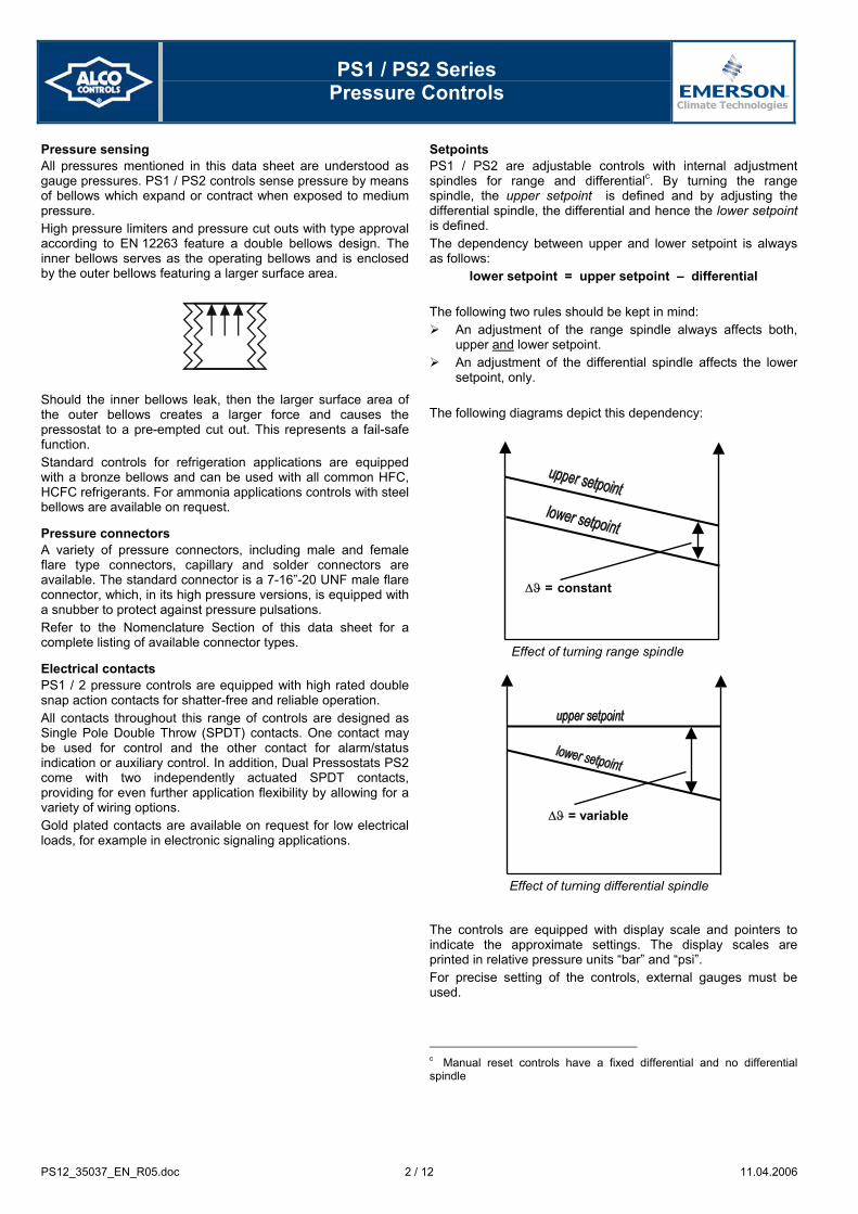
Dual Pressostat PS2 Standards • per Low Voltage Directive • per PED Directive, TÜV approved versions only
EN12263 • Manufactured and tested to standards on our own
responsibility
• Underwriter Laboratories
• German Lloyd for use on ships (only when equipped with marine-type cable gland)
Introduction The PS1 / PS2 Series is ALCO’s range of adjustable pressos-tats for application in refrigeration and heat pump systems. In these systems, pressure controls serve various functions, which may be divided into control and protection functions. Examples for control functions are compressor cycling, pump-down or defrost control. Protection functions include, pressure limiting and cut out against excessive pressures, against loss of charge or for freeze protection. Whereas the need for control functions is mainly founded in the desire for acceptable or optimized system performance, protection functions are normally requested by national legislation. National and international standards assist in meeting these legal requirements. Standardization is an ongoing process in the European Community and where this data sheet makes reference to national standards, corres-ponding European standards are referenced as far as known. The most important standards for safety requirements in refrigeration systems are EN 378a and DIN 8901. a DIN 8975
DIN 8901 defines safety and environmental requirements for the protection of soil, ground and surface water. In simple terms, when applied to pressure controls, DIN 8901 aims at the prevention of refrigerant charge leaking to the environment. Pressure controls designed and tested according to EN 12263b
fulfill the requirements of DIN 8901. DIN 8975 is concerned with control devices in refrigeration plants for protection against unpermissible pressure stresses. It also asks for pressure controls, which are approved in accordance with EN 12263. The ALCO PS1 / PS2 series includes products, which are designed and tested in accordance with EN 12263 and can therefore be used in order to meet the requirements of DIN 8901 and EN 378. b DIN 32733
PS1 / PS2 Series
Pressure Controls
PS12_35037_EN_R05.doc 2 / 12 11.04.2006
Pressure sensing All pressures mentioned in this data sheet are understood as gauge pressures. PS1 / PS2 controls sense pressure by means of bellows which expand or contract when exposed to medium pressure. High pressure limiters and pressure cut outs with type approval according to EN 12263 feature a double bellows design. The inner bellows serves as the operating bellows and is enclosed by the outer bellows featuring a larger surface area.
Should the inner bellows leak, then the larger surface area of the outer bellows creates a larger force and causes the pressostat to a pre-empted cut out. This represents a fail-safe function. Standard controls for refrigeration applications are equipped with a bronze bellows and can be used with all common HFC, HCFC refrigerants. For ammonia applications controls with steel bellows are available on request.
Pressure connectors A variety of pressure connectors, including male and female flare type connectors, capillary and solder connectors are available. The standard connector is a 7-16”-20 UNF male flare connector, which, in its high pressure versions, is equipped with a snubber to protect against pressure pulsations. Refer to the Nomenclature Section of this data sheet for a complete listing of available connector types.
Electrical contacts PS1 / 2 pressure controls are equipped with high rated double snap action contacts for shatter-free and reliable operation. All contacts throughout this range of controls are designed as Single Pole Double Throw (SPDT) contacts. One contact may be used for control and the other contact for alarm/status indication or auxiliary control. In addition, Dual Pressostats PS2 come with two independently actuated SPDT contacts, providing for even further application flexibility by allowing for a variety of wiring options. Gold plated contacts are available on request for low electrical loads, for example in electronic signaling applications.
Setpoints PS1 / PS2 are adjustable controls with internal adjustment spindles for range and differentialc. By turning the range spindle, the upper setpoint is defined and by adjusting the differential spindle, the differential and hence the lower setpoint is defined. The dependency between upper and lower setpoint is always as follows:
lower setpoint = upper setpoint – differential
The following two rules should be kept in mind: An adjustment of the range spindle always affects both,
upper and lower setpoint. An adjustment of the differential spindle affects the lower
setpoint, only. The following diagrams depict this dependency: The controls are equipped with display scale and pointers to indicate the approximate settings. The display scales are printed in relative pressure units “bar” and “psi”. For precise setting of the controls, external gauges must be used. c Manual reset controls have a fixed differential and no differential spindle
Effect of turning range spindle
∆ϑ = constant
Effect of turning differential spindle
∆ϑ = variable

PS1 / PS2 Series
Pressure Controls
PS12_35037_EN_R05.doc 3 / 12 11.04.2006
Contact function Contacts on Single Pressostats PS1 are labeled 1-2-4 where ‘1’ refers to the common pole, ‘2’ refers to the lower setpoint and ‘4’ refers to the uppers setpoint. This is true for all types of controls, irrespective whether they are low pressure controls, high pressure controls, manual or automatic reset types. The contact function for automatic and manual reset versions is as described below. Automatic reset On pressure rise above the upper setpoint, contacts 1-2 open and contacts 1-4 close. On decreasing pressure below lower setpoint contacts 1-4 open and contacts 1-2 close.
Automatic reset contact function
Manual reset low pressure On decreasing pressure below the lower setpoint, contacts 1-4 open, contacts 1-2 close and latch. Only on pressure rise above upper setpoint and after pressing the manual reset button contacts 1-2 will open and contacts 1-4 will close again.
Manual reset low pressure contact function
Manual reset high pressure On increasing pressure above the upper setpoint, contacts 1-2 open, contacts 1-4 close and latch. Only on falling pressure below lower setpoint and after pressing the manual reset button, contacts 1-4 will open and contacts 1-2 will close again.
Manual reset high pressure contact function
For operational safety, all PS1 / PS2 with manual reset are designed as trip-free controls, i.e. pressing the manual reset button while the pressure has not reached its reset threshold will not operate the electrical contacts. The contact function for controls with internal and external manual reset is alike. The only difference between the two is that for internal manual reset the cover has to be undone, whereas the external reset controls can be reset without removing the cover. As Dual Pressostats PS2 have two complete sets of contacts, their function is the same as on Single Pressostats PS1 with the only difference that the contact labels are preceded by an additional index. One side of the control is labeled 11-12-14 whereas the second side is 21-22-24. The contact function of controls with convertible reset is as described above but depends on the actual position of the convertible reset toggle, i.e. automatic or manual reset position.
Installation and maintenance Controls come with a lockplate which may be used to protect the settings by wire-seal if desired. Range and differential spindle may be sealed independent from each other. A front access manual toggle is provided for checking out control operation. On low pressure controls this toggle may be used to override the low pressure signal during system evacuation, avoiding the need to undo the electrical wiring for this purpose. All PS1 / PS2 controls come with heavy duty terminal blocks which are finger-proof and feature wire clamps plus non-loosable terminal screws for ease of wiring. Available accessories include mounting brackets of various types, including flat and angle brackets. A universal mounting bracket which matches the most common whole patterns encounted in the field is also available. The standard mounting holes for mounting brackets are equipped with a universal thread to fit both, M4 and UNC 8-32 screws. The standard wholesale package includes two mounting screws. Several hole patterns for surface mounting are provided.
PS1 / PS2 Series
Pressure Controls
PS12_35037_EN_R05.doc 4 / 12 11.04.2006
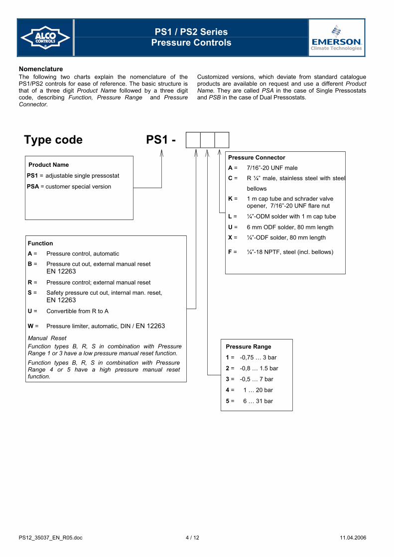
Nomenclature The following two charts explain the nomenclature of the PS1/PS2 controls for ease of reference. The basic structure is that of a three digit Product Name followed by a three digit code, describing Function, Pressure Range and Pressure Connector.
Customized versions, which deviate from standard catalogue products are available on request and use a different Product Name. They are called PSA in the case of Single Pressostats and PSB in the case of Dual Pressostats.
Type code PS1 -
Product Name
PS1 = adjustable single pressostat
PSA = customer special version
Pressure Range
1 = -0,75 … 3 bar
2 = -0,8 … 1.5 bar
3 = -0,5 … 7 bar
4 = 1 … 20 bar
5 = 6 … 31 bar
Function A = Pressure control, automatic
B = Pressure cut out, external manual reset EN 12263
R = Pressure control; external manual reset
S = Safety pressure cut out, internal man. reset, EN 12263
U = Convertible from R to A
W = Pressure limiter, automatic, DIN / EN 12263
Manual Reset Function types B, R, S in combination with PressureRange 1 or 3 have a low pressure manual reset function. Function types B, R, S in combination with Pressure Range 4 or 5 have a high pressure manual reset function.
Pressure Connector A = 7/16”-20 UNF male
C = R ¼” male, stainless steel with steel
bellows
K = 1 m cap tube and schrader valve opener, 7/16”-20 UNF flare nut
L = ¼”-ODM solder with 1 m cap tube
U = 6 mm ODF solder, 80 mm length
X = ¼”-ODF solder, 80 mm length
F = ¼”-18 NPTF, steel (incl. bellows)

PS1 / PS2 Series
Pressure Controls
PS12_35037_EN_R05.doc 5 / 12 11.04.2006
Type code PS2 -
Product Name PS2 = adjustable dual pressostat
PSB = customer special version
Pressure Connector A = 7/16”-20 UNF male
C = R ¼” male, stainless steel with steel bellows
K = 1 m cap tube and schrader valve opener, 7/16”-20 UNF flare nut
L = ¼”-ODM solder with 1 m cap tube
U = 6 mm ODF solder, 80 mm length
X = ¼”-ODF solder, 80 mm length
F = ¼”-18 NPTF, steel (incl. bellows)
Pressure Range 7 = -0.5 … 7 bar 6 … 31 bar 8 = 6 … 31 bar 6 … 31 bar 9 = -0.75 … 3 bar 6 … 31 bar
Function A = both sides: automatic pressure controls B = both sides: cut out, external manual reset, EN 12263 C = left side: pressure limiter, automatic, EN 12263 right side: cut out, external manual reset, EN 12263 G = left side: cut out, external manual reset, EN 12263
right side: safety cut out, internal manual reset, EN 12263
L = left side: automatic pressure control, right side: external manual reset. M = left side: automatic pressure control, right side: convertible from R to A. R = both sides: external manual reset S = both sides: safety cut out, internal manual reset, EN 12263 T = left side: pressure limiter, automatic, EN 12263
right side: safety cut out, internal manual reset, EN 12263
U = both sides: convertible from R to A W = both sides: pressure limiter, automatic, EN 12263 Manual Reset Cut outs with manual reset function and in combination with the low pressure side of pressure ranges 7 and 9 have a low pressure reset function. Cut outs with manual reset function and in combination with the high pressure side of pressure ranges 7 and 9 have a high pressure reset function.

PS1 / PS2 Series
Pressure Controls
PS12_35037_EN_R05.doc 6 / 12 11.04.2006
Technical data
Environmental conditions Materials and compatibility Ambient temperatures
storage and transportation: operation:
-50 °C to +70 °C -50 °C to +70 °C
Housing materials cover: frame:
Polycarbonate (PC) Steel, yellow chromated
Medium temperature range at pressure connector TS:
-50 °C to +70 °C
Materials with medium contact pressure conn. (A) / bellows:
brass /bronze
Dust and water protection EN 60529 / IEC 529:
IP44 Control mounted flush against wall!
pressure conn. (C) / bellows: pressure conn. (K,L) / bellows:
stainless steel / steel copper / bronze
Vibration resistance: 4g @ 10 … 1000 Hz Medium compatibility HFC, HCFC NOTE: PS1/PS2 are not released for use with inflammable refrigerants
Electrical contacts Approvals Type of contacts - PS1: - PS2:
1 x SPDT contact 2 x SPDT contacts
EN 12263 (TÜV) required by DIN 8901 and DIN 8975:
specific models (approval pending)
Contact material - standard: - options:
CuAg3 gold plated contacts
Low Voltage Directive 73/23/EWG 93/68/EWG;
all models (CE-Label)
Heating load (AC1): 24A / 230V AC EN 60947-1, EN 60947-5-1 Inductive load (AC15): 10A / 230V AC Germanic Lloyd: standard models Inductive load (DC 13): 0.1A / 230V DC
3A / 24V DC 6A / 12V DC
when used with marine cable glands (accessory)
Motor rating UL (FLA): 24A / 120 / 240V AC UL / CSA: all models Locked rotor UL (LRA)/ Startup (AC3): 144A / 120 / 240V AC
Physical dimensions and drawings
30
29
75
3531 25
7064
Ø 4,5
86
7
M4/UNCNo.8-32 Ø 4,5
139
M475
1015
24
60 25
52
40
23
1
44PS1 PS2
1000
Ø 1/4"
1000
80
Ø ¼
80
Ø 6,0 A L K U / X
7/16’’ -20 UNF male (1/4’’SAE)
∅ 1/4’’ Solder Tube with 1m length
1 m capillary tube, Schrader depressor
6 mm / 1/4’’ ODF Solder Tube with 80mm length
25
PS1 / PS2 Series
Pressure Controls
PS12_35037_EN_R05.doc 7 / 12 11.04.2006
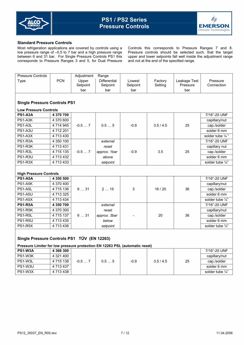
Standard Pressure Controls Most refrigeration applications are covered by controls using a low pressure range of –0.5 to 7 bar and a high pressure range between 6 and 31 bar. For Single Pressure Controls PS1 this corresponds to Pressure Ranges 3 and 5, for Dual Pressure
Controls this corresponds to Pressure Ranges 7 and 8. Pressure controls should be selected such, that the target upper and lower setpoints fall well inside the adjustment range and not at the end of the specified range.
Pressure Controls Adjustment Range Type PCN Upper
Setpoint bar
Differential Setpoint
bar
Lowest Setpoint
bar
Factory Setting
Leakage Test Pressure
bar
Pressure Connection
Single Pressure Controls PS1
Low Pressure Controls PS1-A3A 4 370 700 7/16”-20 UNF PS1-A3K 4 370 600 capillary/nut PS1-A3L 4 714 945 -0.5 … 7 0.5 … 5 -0.9 3.5 / 4.5 25 cap./solder PS1-A3U 4 712 201 solder 6 mm PS1-A3X 4 713 430 solder tube ¼ “ PS1-R3A 4 350 100 external 7/16”-20 UNF PS1-R3K 4 713 431 reset capillary nut PS1-R3L 4 715 135 -0.5 … 7 approx. 1bar -0.9 3.5 25 cap./solder PS1-R3U 4 713 432 above solder 6 mm PS1-R3X 4 713 433 setpoint solder tube ¼”
High Pressure Controls PS1-A5A 4 350 500 7/16”-20 UNF PS1-A5K 4 370 400 capillary/nut PS1-A5L 4 715 136 6 … 31 2 … 15 3 16 / 20 36 cap./solder PS1-A5U 4 713 325 solder 6 mm PS1-A5X 4 713 434 solder tube ¼” PS1-R5A 4 350 700 external 7/16”-20 UNF PS1-R5K 4 370 300 reset capillary/nut PS1-R5L 4 715 137 6 … 31 approx. 3bar - 20 36 cap./solder PS1-R5U 4 713 435 below solder 6 mm PS1-R5X 4 713 436 setpoint solder tube ¼”
Single Pressure Controls PS1 TÜV (EN 12263)
Pressure Limiter for low pressure protection EN 12263 PSL (automatic reset) PS1-W3A 4 368 300 7/16”-20 UNF PS1-W3K 4 321 400 capillary/nut PS1-W3L 4 715 138 -0.5 … 7 0.5 … 5 -0.9 3.5 / 4.5 25 cap./solder PS1-W3U 4 713 437 solder 6 mm PS1-W3X 4 713 438 solder tube ¼”
PS1 / PS2 Series
Pressure Controls
PS12_35037_EN_R05.doc 8 / 12 11.04.2006
Pressure Controls Adjustment Range Type PCN Upper
Setpoint bar
Differential Setpoint
bar
Lowest Setpoint
bar
Factory Setting
Leakage Test Pressure
bar
Pressure Connection
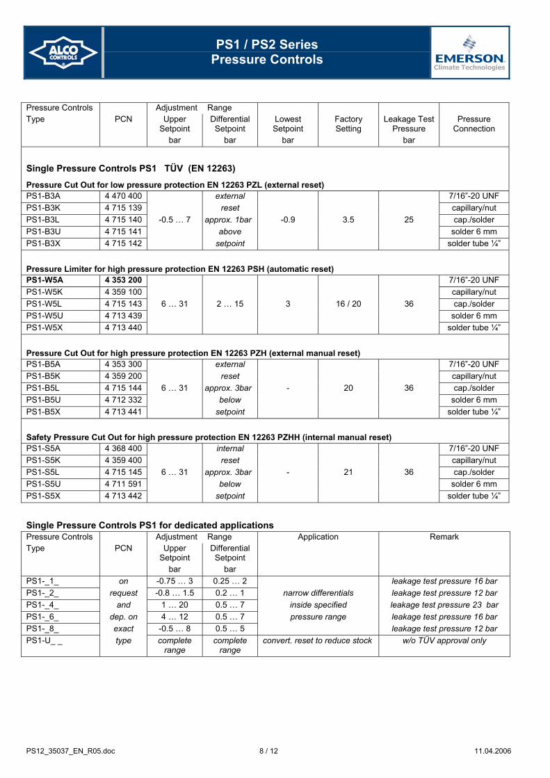
Single Pressure Controls PS1 TÜV (EN 12263)
Pressure Cut Out for low pressure protection EN 12263 PZL (external reset) PS1-B3A 4 470 400 external 7/16”-20 UNF PS1-B3K 4 715 139 reset capillary/nut PS1-B3L 4 715 140 -0.5 … 7 approx. 1bar -0.9 3.5 25 cap./solder PS1-B3U 4 715 141 above solder 6 mm PS1-B3X 4 715 142 setpoint solder tube ¼”
Pressure Limiter for high pressure protection EN 12263 PSH (automatic reset) PS1-W5A 4 353 200 7/16”-20 UNF PS1-W5K 4 359 100 capillary/nut PS1-W5L 4 715 143 6 … 31 2 … 15 3 16 / 20 36 cap./solder PS1-W5U 4 713 439 solder 6 mm PS1-W5X 4 713 440 solder tube ¼”
Pressure Cut Out for high pressure protection EN 12263 PZH (external manual reset) PS1-B5A 4 353 300 external 7/16”-20 UNF PS1-B5K 4 359 200 reset capillary/nut PS1-B5L 4 715 144 6 … 31 approx. 3bar - 20 36 cap./solder PS1-B5U 4 712 332 below solder 6 mm PS1-B5X 4 713 441 setpoint solder tube ¼”
Safety Pressure Cut Out for high pressure protection EN 12263 PZHH (internal manual reset) PS1-S5A 4 368 400 internal 7/16”-20 UNF PS1-S5K 4 359 400 reset capillary/nut PS1-S5L 4 715 145 6 … 31 approx. 3bar - 21 36 cap./solder PS1-S5U 4 711 591 below solder 6 mm PS1-S5X 4 713 442 setpoint solder tube ¼”
Single Pressure Controls PS1 for dedicated applications Pressure Controls Adjustment Range Application Remark Type PCN Upper
Setpoint bar
Differential Setpoint
bar
PS1-_1_ on -0.75 … 3 0.25 … 2 leakage test pressure 16 bar PS1-_2_ request -0.8 … 1.5 0.2 … 1 narrow differentials leakage test pressure 12 bar PS1-_4_ and 1 … 20 0.5 … 7 inside specified leakage test pressure 23 bar PS1-_6_ dep. on 4 … 12 0.5 … 7 pressure range leakage test pressure 16 bar PS1-_8_ exact -0.5 … 8 0.5 … 5 leakage test pressure 12 bar PS1-U_ _ type complete
range complete
range convert. reset to reduce stock w/o TÜV approval only

PS1 / PS2 Series
Pressure Controls
PS12_35037_EN_R05.doc 9 / 12 11.04.2006
Dual Pressure Adjustment Range Factory Setting Leakage Test Pressure Controls Upper Setpoint Differential Pressure Connection Type PCN left
bar right bar
left bar
right bar
left bar
right bar
left bar
right bar
Dual Pressure Controls PS2
Combined Low and High Pressure Controls PS2-A7A 4 353 400 7/16”-20 UNF PS2-A7K 4 350 900 capillary/nut PS2-A7L 4 713 565 -0.5 … 7 6 … 31 0.5a ... 5 ca. 4 fix 3.5 / 4.5 20 25 36 cap./solder PS2-A7U 4 713 415 solder 6 mm PS2-A7X 4 713 416 solder tube ¼ “ PS2-L7A 4 351 100 Ext. reset 7/16”-20 UNF PS2-L7K 4 370 500 approx. capillary nut PS2-L7L 4 440 800 -0.5 … 7 6 … 31 0.5a ... 5 4bar 3.5 / 4.5 20 25 36 cap./solder PS2-L7U 4 713 417 below solder 6 mm PS2-L7X 4 713 418 setpoint solder tube ¼” PS2-R7A 4 351 300 Ext. reset Ext. reset 7/16”-20 UNF PS2-R7K 4 713 421 Approx. approx. capillary nut PS2-R7L 4 715 134 -0.5 … 7 6 … 31 1bar 4bar 3.5 20 25 36 cap./solder PS2-R7U 4 713 419 above below solder 6 mm PS2-R7X 4 713 420 setpoint setpoint solder tube ¼”
Dual Pressure Controls PS2 TÜV (EN 12263)
Combined Pressure Limiter for low Pressure / high pressure protection EN 12263; PSL / PSH (automatic / automatic) PS2-W7A 4 360 100 7/16”-20 UNF PS2-W7K 4 450 200 capillary/nut PS2-W7L 4 450 300 -0.5 … 7 6 … 31 0.5a ... 5 ca. 4 fix 3.5 / 4.5 20 25 36 cap./solder PS2-W7U 4 712 436 solder 6 mm PS2-W7X 4 713 429 solder tube ¼ “
Combined Pressure Limiter / Pressure Cut Out for low Pressure / high pressure protection EN 12263; PSL / PZH (automatic / external manual reset) PS2-C7A 4 353 500 Ext. reset 7/16”-20 UNF PS2-C7K 4 348 400 approx. capillary/nut PS2-C7L 5 715 131 -0.5 … 7 6 … 31 0.5a ... 5 4bar 3.5 / 4.5 20 25 36 cap./solder PS2-C7U 4 713 422 below solder 6 mm PS2-C7X 4 713 423 setpoint solder tube ¼ “
a lowest possible setpoint: -0.9 bar
PS1 / PS2 Series
Pressure Controls
PS12_35037_EN_R05.doc 10 / 12 11.04.2006
Dual Pressure Adjustment Range Factory Setting Leakage Test Pressure Controls Upper Setpoint Differential Pressure Connection Type PCN left
bar right bar
left bar
right bar
left bar
right bar
left bar
right bar
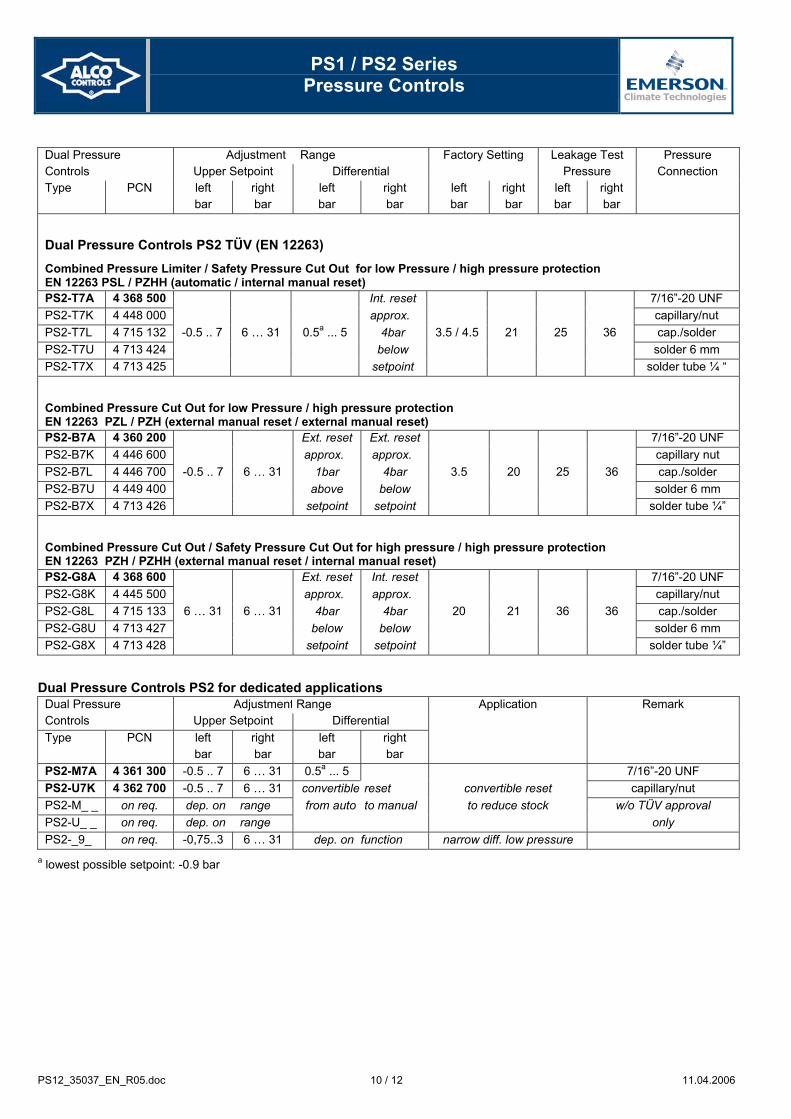
Dual Pressure Controls PS2 TÜV (EN 12263)
Combined Pressure Limiter / Safety Pressure Cut Out for low Pressure / high pressure protection EN 12263 PSL / PZHH (automatic / internal manual reset) PS2-T7A 4 368 500 Int. reset 7/16”-20 UNF PS2-T7K 4 448 000 approx. capillary/nut PS2-T7L 4 715 132 -0.5 .. 7 6 … 31 0.5a ... 5 4bar 3.5 / 4.5 21 25 36 cap./solder PS2-T7U 4 713 424 below solder 6 mm PS2-T7X 4 713 425 setpoint solder tube ¼ “
Combined Pressure Cut Out for low Pressure / high pressure protection EN 12263 PZL / PZH (external manual reset / external manual reset) PS2-B7A 4 360 200 Ext. reset Ext. reset 7/16”-20 UNF PS2-B7K 4 446 600 approx. approx. capillary nut PS2-B7L 4 446 700 -0.5 .. 7 6 … 31 1bar 4bar 3.5 20 25 36 cap./solder PS2-B7U 4 449 400 above below solder 6 mm PS2-B7X 4 713 426 setpoint setpoint solder tube ¼”
Combined Pressure Cut Out / Safety Pressure Cut Out for high pressure / high pressure protection EN 12263 PZH / PZHH (external manual reset / internal manual reset) PS2-G8A 4 368 600 Ext. reset Int. reset 7/16”-20 UNF PS2-G8K 4 445 500 approx. approx. capillary/nut PS2-G8L 4 715 133 6 … 31 6 … 31 4bar 4bar 20 21 36 36 cap./solder PS2-G8U 4 713 427 below below solder 6 mm PS2-G8X 4 713 428 setpoint setpoint solder tube ¼”
Dual Pressure Controls PS2 for dedicated applications Dual Pressure Adjustment Range Application Remark Controls Upper Setpoint Differential Type PCN left
bar right bar
left bar
right bar
PS2-M7A 4 361 300 -0.5 .. 7 6 … 31 0.5a ... 5 7/16”-20 UNF PS2-U7K 4 362 700 -0.5 .. 7 6 … 31 convertible reset convertible reset capillary/nut PS2-M_ _ on req. dep. on range from auto to manual to reduce stock w/o TÜV approval PS2-U_ _ on req. dep. on range only PS2-_9_ on req. -0,75..3 6 … 31 dep. on function narrow diff. low pressure
a lowest possible setpoint: -0.9 bar
PS1 / PS2 Series
Pressure Controls
PS12_35037_EN_R05.doc 11 / 12 11.04.2006
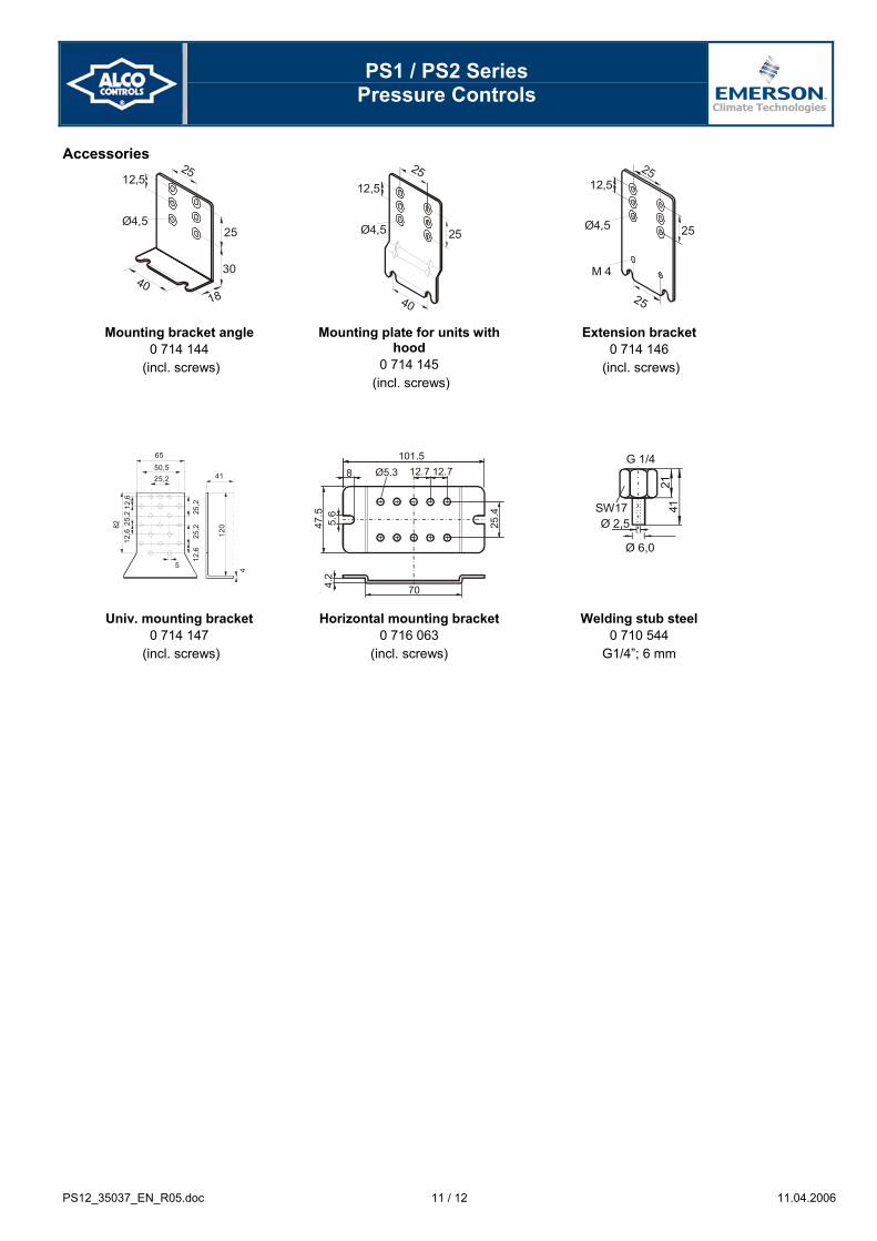
Accessories 12,5
Ø4,525
30
25
1840
25
25
Ø4,5
12,5
40 25
M 4
Ø4,5
12,525
25
Mounting bracket angle 0 714 144
(incl. screws)
Mounting plate for units with hood
0 714 145 (incl. screws)
Extension bracket 0 714 146
(incl. screws)
12,6
25,2
12,6
82
65
50,525,2
25,2
25,2
12,6
5
120
4
41
101.512.7 12.78
47.5
5.6
Ø5.3
25.4
4.2
70
SW17
G 1/4
Ø 2,5
Ø 6,0
2141
Univ. mounting bracket 0 714 147
(incl. screws)
Horizontal mounting bracket 0 716 063
(incl. screws)
Welding stub steel 0 710 544
G1/4”; 6 mm
PS1 / PS2 Series
Pressure Controls
PS12_35037_EN_R05.doc 12 / 12 11.04.2006
ALCO CONTROLS is not to be held responsible for erroneous literature regarding capacities, dimensions, applications, etc. stated herein. Products, specifications and data in this literature are subject to change without notice. The information given herein is based on technical data and tests which ALCO CONTROLS believes to be reliable and which are in compliance with technical knowledge of today. It is intended only
for use by persons having the appropriate technical knowledge and skills, at their own discretion and risk. Since conditions of use are outside of ALCO'S control we can not assume any liability for results obtained or damages occurred due to improper application. This document replaces all earlier versions.
Emerson Electric GmbH & Co. OHG ALCO CONTROLS Heerstraße 111 D-71332 Waiblingen Germany Phone ...49-(0)7151-509-0 Fax ...49-(0)7151-509-200 www.eCopeland.com/alcoliterature.cfm
Benelux Denmark & Finland Eastern Europe, Turkey & Iran France, Greece, Maghreb Deutschland, Österreich, SchweizItalia Middle East & Africa Poland Russia & Cis España & Portugal Sweden & Norway UK & Ireland
Phone.: +31 (0)773 240 234 +32 (0)87 305 565 +32 (0)87 305 061 +33 (0)478 668 570 +49 (0)6109 6059 0 +39 02 961 78 1 +97 148 832 828 +48 (0)22 458 9205 +7 495 981 9811 +34 93 4 123 752 +32 (0)87 305 565 +44 (0)1 635 876 161
Fax: +31 (0)773 240 235 +49 24 08 929 568 +32 (0)87 305 506 +33 (0)478 668 571 +49 (0)6109 6059 40 +39 02 961 78 888 +97 148 832 848 +48 (0)22 458 9255 +7 495 981 9816 +34 93 4 124 215 +49 24 08 929 568 +44 (0)1 635 877 111


![1N2] 101\ 512%' PS1 PS2](https://img.pdfslide.net/doc/110x75/5899a9641a28abce458b8663/1n2-101-512-ps1-ps2.jpg)