Embed Size (px)
DESCRIPTION
u
Citation preview

PS-1
POWER STEERING SYSTEM
G STEERING
CONTENTS
C
D
E
F
H
I
J
K
L
M
SECTION
A
B
PS
Revision: July 2005 2005 Sentra
PRECAUTIONS .......................................................... 2Precautions for Supplemental Restraint System (SRS) “AIR BAG” and “SEAT BELT PRE-TEN-SIONER” .................................................................. 2Precautions for Steering System .............................. 2
PREPARATION ........................................................... 3Special Service Tools ............................................... 3Commercial Service Tool ......................................... 5
NOISE, VIBRATION, AND HARSHNESS(NVH) TROUBLESHOOTING ................................................ 6
NVH Troubleshooting Chart ..................................... 6ON-VEHICLE SERVICE ............................................. 7
Checking Steering Wheel Play ................................. 7Checking Neutral Position on Steering Wheel ......... 7
PRE-CHECKING ................................................... 7CHECKING ........................................................... 7
Front Wheel Turning Angle ...................................... 7Checking Gear Housing Movement ......................... 8Checking and Adjusting Drive Belts ......................... 8Checking Fluid Level ................................................ 8Checking Fluid Leakage ........................................... 8Bleeding Hydraulic System ...................................... 8Checking Steering Wheel Turning Force .................. 9Checking Hydraulic System ................................... 10
STEERING WHEEL AND STEERING COLUMN ......11Components ............................................................11Removal and Installation .........................................11
STEERING WHEEL .............................................11STEERING COLUMN ......................................... 12
Disassembly and Assembly .................................... 13Inspection ............................................................... 14
TILT MECHANISM .............................................. 14POWER STEERING GEAR AND LINKAGE ............ 15
Components ........................................................... 15Removal and Installation ........................................ 16
REMOVAL ........................................................... 16INSTALLATION ................................................... 17
Disassembly ........................................................... 18Inspection ............................................................... 18
BOOT .................................................................. 18TIE-ROD OUTER AND INNER SOCKETS ......... 19
Assembly ................................................................ 19POWER STEERING OIL PUMP ............................... 21
Removal and Installation ........................................ 21REMOVAL ........................................................... 21INSTALLATION ................................................... 21
Disassembly and Assembly .................................... 22PRE-DISASSEMBLY INSPECTION .................... 22DISASSEMBLY ................................................... 23INSPECTION ...................................................... 23ASSEMBLY ......................................................... 23
HYDRAULIC LINE .................................................... 25Removal and Installation ........................................ 25
SERVICE DATA AND SPECIFICATIONS (SDS) ...... 27General Specifications ............................................ 27Steering Wheel ....................................................... 27Steering Column ..................................................... 27Steering Gear and Linkage ..................................... 27Power Steering ....................................................... 28

PS-2
PRECAUTIONS
Revision: July 2005 2005 Sentra
PRECAUTIONS PFP:00001
Precautions for Supplemental Restraint System (SRS) “AIR BAG” and “SEAT BELT PRE-TENSIONER” EGS000FE
The Supplemental Restraint System such as “AIR BAG” and “SEAT BELT PRE-TENSIONER”, used alongwith a front seat belt, helps to reduce the risk or severity of injury to the driver and front passenger for certaintypes of collision. Information necessary to service the system safely is included in the SRS and SB section ofthis Service Manual.WARNING:● To avoid rendering the SRS inoperative, which could increase the risk of personal injury or death
in the event of a collision which would result in air bag inflation, all maintenance must be per-formed by an authorized NISSAN/INFINITI dealer.
● Improper maintenance, including incorrect removal and installation of the SRS, can lead to per-sonal injury caused by unintentional activation of the system. For removal of Spiral Cable and AirBag Module, see the SRS section.
● Do not use electrical test equipment on any circuit related to the SRS unless instructed to in thisService Manual. SRS wiring harnesses can be identified by yellow and/or orange harnesses orharness connectors.
Precautions for Steering System EGS000FF
● Before disassembly, thoroughly clean the outside of the unit.● Disassembly should be done in a clean work area. It is important to prevent the internal parts from
becoming contaminated by dirt or other foreign matter.● For easier and proper assembly, place disassembled parts in order on a parts rack.● Use nylon cloths or paper towels to clean the parts; common shop rags can leave lint that might
interfere with their operation.● Before inspection or reassembly, carefully clean all parts with a general purpose, non-flammable
solvent.● Before assembly, apply a coat of recommended Genuine NISSAN PSF or equivalent to hydraulic
parts. Petroleum jelly may be applied to O-rings and seals. Do not use any grease.● Replace all gaskets, seals and O-rings. Avoid damaging O-rings, seals and gaskets during installa-
tion. Perform functional tests whenever designated.
PREPARATION
PS-3
C
D
E
F
H
I
J
K
L
M
A
B
PS
Revision: July 2005 2005 Sentra
PREPARATION PFP:00002
Special Service Tools EGS000FG
The actual shapes of Kent-Moore tools may differ from those of special service tools illustrated here.
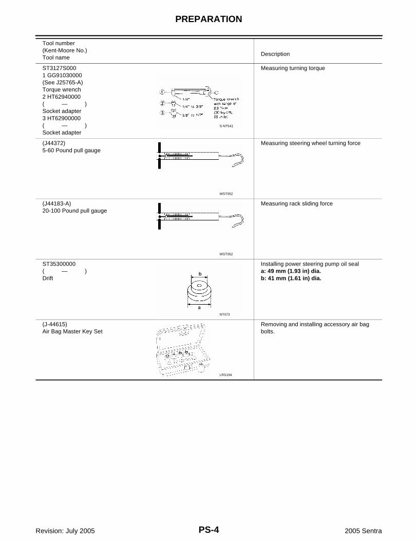
Tool number(Kent-Moore No.)Tool name
Description
KV48101100(J26364)Torque adapter
Measuring pinion rotating torque
ST27180001(J25726-B)Steering wheel puller
Removing steering wheel
HT72520000(J25730-B)Ball joint remover
Removing tie-rod and lower ball jointa: 33 mm (1.30 in)b: 50 mm (1.97 in)r: R11.5 mm (0.453 in)
(J-24319-B)Tie rod puller
Remove outer tie rod
KV48103500(J26357 and J26357-10)Pressure gauge
Measuring oil pressure
KV48102500(J33914)Pressure gauge adapter
Measuring oil pressure
NT169
S-NT544
NT546
LGIA0007E
S-NT547
S-NT542
PS-4
PREPARATION
Revision: July 2005 2005 Sentra
ST3127S0001 GG91030000(See J25765-A)Torque wrench2 HT62940000( — )Socket adapter3 HT62900000( — )Socket adapter
Measuring turning torque
(J44372)5-60 Pound pull gauge
Measuring steering wheel turning force
(J44183-A)20-100 Pound pull gauge
Measuring rack sliding force
ST35300000( — )Drift
Installing power steering pump oil seala: 49 mm (1.93 in) dia.b: 41 mm (1.61 in) dia.
(J-44615)Air Bag Master Key Set
Removing and installing accessory air bag bolts.
Tool number(Kent-Moore No.)Tool name
Description
S-NT541
WST052
WST052
NT073
LRS194

PREPARATION
PS-5
C
D
E
F
H
I
J
K
L
M
A
B
PS
Revision: July 2005 2005 Sentra
Commercial Service Tool EGS000FH
Tool numberDescription
Power steering pump attachment Disassembling and assembling power steer-ing pumpUnit: mm (in)
10 mm Drift Installing power steering pump snap ring
S-NT179
LST027

PS-6
NOISE, VIBRATION, AND HARSHNESS(NVH) TROUBLESHOOTING
Revision: July 2005 2005 Sentra
NOISE, VIBRATION, AND HARSHNESS(NVH) TROUBLESHOOTING PFP:00003
NVH Troubleshooting Chart EGS000FI
Use the chart below to help you find the cause of the symptom. If necessary, repair or replace these parts.
×: Applicable
Reference pageR
efer
to P
S-8
Ref
er to
PS
-8
Ref
er to
PS
-19
Ref
er to
PS
-19
Ref
er to
PS
-19
Ref
er to
PS
-8
Ref
er to
PS
-7
Ref
er to
PS
-9
MA
-16,
"C
heck
ing
Driv
e B
elts
", M
A-2
3, "
Che
ckin
g D
rive
Bel
ts"
Ref
er to
PS
-11
Ref
er to
PS
-14
Ref
er to
PS
-8
Ref
er to
PS
-14
Ref
er to
PS
-12
Ref
er to
PS
-12
FAX
-4, "
NV
H T
roub
lesh
ootin
g C
hart
"
FAX
-4, "
NV
H T
roub
lesh
ootin
g C
hart
"
FS
U-4
, "N
VH
Tro
uble
shoo
ting
Cha
rt"
WT-
2, "
NV
H T
roub
lesh
ootin
g C
hart
"
WT-
2, "
NV
H T
roub
lesh
ootin
g C
hart
"
BR
-5, "
NV
H T
roub
lesh
ootin
g C
hart
"
Possible cause and SUSPECTED PARTS
Flu
id le
vel
Air
in h
ydra
ulic
sys
tem
Tie-
rod
ball
join
t sw
ingi
ng fo
rce
Tie-
rod
ball
join
t rot
atin
g to
rque
Tie-
rod
ball
join
t end
pla
y
Ste
erin
g ge
ar fl
uid
leak
age
Ste
erin
g w
heel
pla
y
Ste
erin
g ge
ar r
ack
slid
ing
forc
e
Driv
e be
lt lo
osen
ess
Impr
oper
ste
erin
g w
heel
Impr
oper
inst
alla
tion
or lo
osen
ess
or ti
lt lo
ck le
ver
Mou
ntin
g ru
bber
det
erio
ratio
n
Ste
erin
g co
lum
n de
form
atio
n or
dam
age
Impr
oper
inst
alla
tion
or lo
osen
ess
of s
teer
ing
colu
mn
Ste
erin
g lin
kage
loos
enes
s
DR
IVE
SH
AF
T
AX
LE
SU
SP
EN
SIO
N
TIR
ES
RO
AD
WH
EE
L
BR
AK
ES
Symptom STEERING
Noise × × × × × × × × × × × × × × ×
Shake × × × × × × × × ×
Vibration × × × × × × × × ×
Shimmy × × × × × × × × ×
Judder × × × × × × ×
ON-VEHICLE SERVICE
PS-7
C
D
E
F
H
I
J
K
L
M
A
B
PS
Revision: July 2005 2005 Sentra
ON-VEHICLE SERVICE PFP:00000
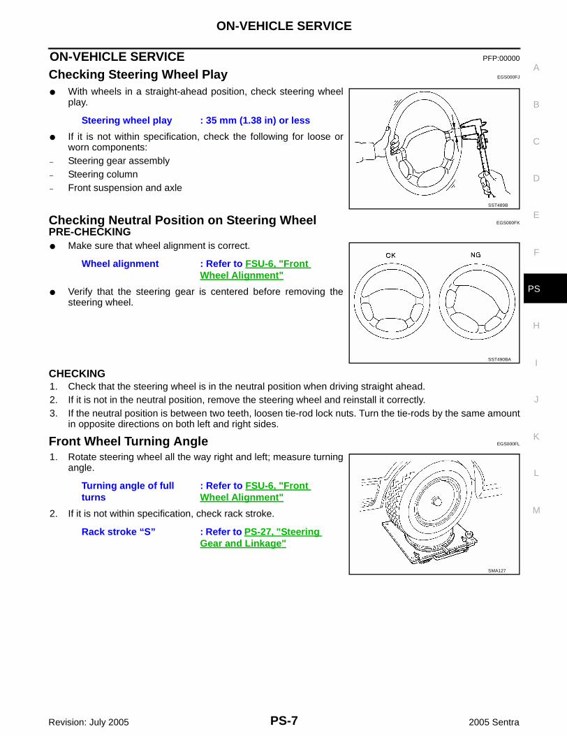
Checking Steering Wheel Play EGS000FJ
● With wheels in a straight-ahead position, check steering wheelplay.
● If it is not within specification, check the following for loose orworn components:
– Steering gear assembly– Steering column– Front suspension and axle
Checking Neutral Position on Steering Wheel EGS000FK
PRE-CHECKING● Make sure that wheel alignment is correct.
● Verify that the steering gear is centered before removing thesteering wheel.
CHECKING1. Check that the steering wheel is in the neutral position when driving straight ahead.2. If it is not in the neutral position, remove the steering wheel and reinstall it correctly.3. If the neutral position is between two teeth, loosen tie-rod lock nuts. Turn the tie-rods by the same amount
in opposite directions on both left and right sides.
Front Wheel Turning Angle EGS000FL
1. Rotate steering wheel all the way right and left; measure turningangle.
2. If it is not within specification, check rack stroke.
Steering wheel play : 35 mm (1.38 in) or less
SST489B
Wheel alignment : Refer to FSU-6, "Front Wheel Alignment"
SST490BA
Turning angle of full turns
: Refer to FSU-6, "Front Wheel Alignment"
Rack stroke “S” : Refer to PS-27, "Steering Gear and Linkage"
SMA127

PS-8
ON-VEHICLE SERVICE
Revision: July 2005 2005 Sentra
Checking Gear Housing Movement EGS000FM
1. Check the movement of steering gear housing during stationarysteering on a dry paved surface.● Apply a force of 49 N (5 kg, 11 lb) to steering wheel to check
the gear housing movement.Turn off ignition key while checking.
2. If movement exceeds the limit, replace mount insulator afterconfirming proper installation of gear housing clamps.
Checking and Adjusting Drive Belts EGS000FN
Refer to MA-16, "Checking Drive Belts" (QG18DE), MA-23, "Checking Drive Belts" (QR25DE).
Checking Fluid Level EGS000FO
Check fluid level, referring to the scale on reservoir tank.● Use “HOT” range for fluid temperatures of 50 - 80°C (122 -
176°F).● Use “COLD” range for fluid temperatures of 0 - 30°C (32 - 86°F).CAUTION:● Do not overfill.● Recommended fluid is Genuine NISSAN PSF or equivalent.
Refer to MA-13, "Fluids and Lubricants" .
Checking Fluid Leakage EGS000FP
Check the lines for improper attachment and for leaks, cracks, dam-age, loose connections, chafing and deterioration.1. Run engine between idle speed and 1,000 rpm.
● Make sure temperature of fluid in oil tank rises to 60 - 80°C(140 - 176°F).
2. Turn steering wheel right-to-left several times.3. Hold steering wheel at each “lock” position for five seconds and
carefully check for fluid leakage.CAUTION:Do not hold the steering wheel in a locked position for morethan 15 seconds.
4. If fluid leakage at connectors is noticed, shut off engine, then loosen and retighten flare nut.CAUTION:Do not overtighten connector as this can damage O-ring, washer and connector.
5. If fluid leakage from power steering pump is noticed, check power steering pump. Refer to PS-22, "PRE-DISASSEMBLY INSPECTION" .
6. Check dust boots for accumulation of power steering fluid.
Bleeding Hydraulic System EGS000FQ
1. Raise front end of vehicle until wheels are clear of the ground.2. Add fluid into reservoir tank to specified level. Then quickly turn steering wheel fully to right and left and
lightly touch steering stoppers.3. Repeat steering wheel operation until fluid level no longer decreases.4. Start engine and repeat step 2 above.
● If any of the following occurs, bleed air again:
Movement of gear housing
: ±2 mm (±0.08 in) or less
SST663B
WGIA0107E
WST032

ON-VEHICLE SERVICE
PS-9
C
D
E
F
H
I
J
K
L
M
A
B
PS
Revision: July 2005 2005 Sentra
– Air bubbles in reservoir tank– Clicking noise in oil pump– Excessive buzzing in oil pump
Fluid noise may occur in the valve or oil pump. This is common when the vehicle is stationary or while turningthe steering wheel slowly. This does not affect the performance or durability of the system.
Checking Steering Wheel Turning Force EGS000FR
1. Park vehicle on a level, dry surface and set parking brake.2. Start engine.3. Bring power steering fluid up to adequate operating tempera-
ture. [Make sure temperature of fluid is approximately 60 - 80°C(140 - 176°F).]
4. Check steering wheel turning force using Tool when steeringwheel has been turned 360° from the neutral position.NOTE:Tires need to be inflated to normal pressure.
5. If steering wheel turning force is out of specification, check racksliding force as follows.
a. Disconnect steering column lower joint and knuckle arms fromthe gear.
b. Start and run engine at idle to make sure steering fluid hasreached normal operating temperature.
c. Pull tie-rod using Tool slowly to move it from neutral position to±11.5 mm (±0.453 in) at speed of 3.5 mm (0.138 in)/s. Checkthat rack sliding force is within specification.
d. Check sliding force outside the above range at rack speed of 40 mm (1.75 in)/s.
6. If rack sliding force is not within specification, overhaul steering gear assembly.7. If rack sliding force is OK, inspect steering column. Refer to PS-14, "Inspection" .
Tool number : J-44372-A
Steering wheel turning force
: 39 N (4 kg, 9 lb) or less
WST047
Tool number : J-44183-A
Average rack sliding force (QG18DE models)
: 210 - 325 N (21.5 - 33.2 kg, 47.4 - 73.2 lb)
Average rack sliding force (QR25DE models)
: 160 - 350 N (16.3 - 35.7 kg, 36.0 - 78.7 lb)
Maximum force devia-tion
: 98 N (10 kg, 22 lb)
Maximum rack sliding force
: Not more than 294 N (30 kg, 66 lb)
Maximum force deviation
: 147 N (15 kg, 33 lb)
WST048

PS-10
ON-VEHICLE SERVICE
Revision: July 2005 2005 Sentra
Checking Hydraulic System EGS000FS
Before starting, check belt tension, driving pulley and tire pressure.1. Set Tool. Open shut-off valve. Then bleed air. Refer to PS-8,
"Bleeding Hydraulic System" .
2. Run engine at idle speed or 1,000 rpm.NOTE:Make sure temperature of fluid in tank rises to 60 - 80°C (140 -176°F).WARNING:Warm up engine with shut-off valve fully opened. If engine is started with shut-off valve closed,fluid pressure in oil pump increases to maximum. This will raise oil temperature abnormally.
3. Check pressure with steering wheel fully turned to left and right positions with engine idling at 1,000 rpm.CAUTION:Do not hold the steering wheel in a locked position for more than 15 seconds.
● If pressure reaches maximum operating pressure, system is OK.● If pressure increases above maximum operating pressure, check power steering pump flow control
valve. Refer to PS-22, "Disassembly and Assembly" .4. If power steering pressure is below the maximum operating pressure, slowly close shut-off valve and
check pressure again.CAUTION:Do not close shut-off valve for more than 15 seconds.● If pressure increases to maximum operating pressure, gear is damaged. Refer to PS-16, "Removal and
Installation" .● If pressure remains below maximum operating pressure, pump is damaged. Refer to PS-23, "DISAS-
SEMBLY" .5. After checking hydraulic system, remove Tool and add fluid as necessary. Then completely bleed air out
of system. Refer to PS-8, "Bleeding Hydraulic System" .
Tool numbers : KV48103500 (J-26357 and J-26357-10): KV48102500 (J-33914)
Oil pump maximum standard pressureQG18DE : 7,649 - 8,238 kPa (78 - 84 kg/cm2 , 1,109 - 1,194
psi)QR25DE : 8,000 - 8,800 kPa (82 - 90 kg/cm2 , 1,160 - 1,276
psi)
SST834-F

STEERING WHEEL AND STEERING COLUMN
PS-11
C
D
E
F
H
I
J
K
L
M
A
B
PS
Revision: July 2005 2005 Sentra
STEERING WHEEL AND STEERING COLUMN PFP:48430
Components EGS000FT
CAUTION:● The rotation of the spiral cable (SRS “Air bag” component part) is limited. If the steering gear must
be removed, set the front wheels in the straight-ahead direction. Do not rotate the steering columnwhile the steering gear is removed.
● Remove the steering wheel before removing the steering lower joint to avoid damaging the SRSspiral cable.
Removal and Installation EGS000FU
STEERING WHEEL1. Remove air bag module. Refer to SRS-41, "Removal and Installation" .2. Remove steering wheel mounting nut.3. Remove steering wheel using Tool.
4. Installation is in the reverse order of removal.
1. Air bag module 2. Steering wheel 3. Spiral cable
4. Side lid LH 5. Column cover 6. Combination switch
7. Steering column assembly 8. Steering column lower cover 9. Lower joint
WGIA0002E
Tool number : ST27180001 (J25726-B)
WST004

PS-12
STEERING WHEEL AND STEERING COLUMN
Revision: July 2005 2005 Sentra
STEERING COLUMNRemovalCAUTION:● The rotation of the spiral cable (SRS “Air Bag” component part) is limited. If the steering gear must
be removed, set the front wheels in the straight-ahead direction. Do not rotate the steering columnwhile the steering gear is removed.
● Remove the steering wheel before removing the steering lower joint to avoid damaging the SRSspiral cable.
1. Disconnect the battery negative terminal.2. Remove the steering wheel. Refer to PS-11, "STEERING WHEEL" .3. Removal spiral cable. Refer to SRS-43, "Removal and Installation" .4. Disconnect data link connector.5. Remove lower instrument panel and lower reinforcement panel. Refer to IP-10, "Removal and Installation"
.6. Remove the column covers.7. Disconnect electrical connectors.8. Remove three screws securing combination switch and remove combination switch.9. Remove key interlock cable (A/T models).10. Remove the hole cover, then remove bolt from lower joint.11. Remove the steering column lower cover.12. Remove four nuts securing steering column and remove steer-
ing column.
Installation1. Installation is the reverse order of removal.
● When installing steering column, finger tighten all lowerbracket and clamp retaining bolts; then tighten them securely.Do not apply undue stress to steering column.
● When attaching coupling joint, be sure tightening bolt facescutout portion.
● Align slit of lower joint with projection on dust cover. Insertjoint until surface A contacts surface B.
CAUTION:After installation, turn steering wheel to make sure it movessmoothly. Ensure the number of turns are the same fromthe straight forward position to left and right locks. Be surethat the steering wheel is in a neutral position when drivingstraight ahead.
SST329C
SST800A
SST491C

STEERING WHEEL AND STEERING COLUMN
PS-13
C
D
E
F
H
I
J
K
L
M
A
B
PS
Revision: July 2005 2005 Sentra
Disassembly and Assembly EGS000FV
● When disassembling and assembling, unlock steering lock withkey.
● Install lock nut on steering column shaft and tighten the nut.
● Steering lock:– Break self-shear type screws using a drill or other appropriate
tool.
1. Combination switch 2. Lock nut 3. Jacket tube assembly
4. Tilt lever 5. Tilt lever stopper 6. Steering column mounting bracket
7. Spring 8. Adjust bolt 9. Adjust bolt stopper
10. Nut 11. Column shaft assembly 12. Steering column lower cover
13. Hole cover seal 14. Hole cover 15. Lower joint
WGIA0003E
SST490C
SST741A

PS-14
STEERING WHEEL AND STEERING COLUMN
Revision: July 2005 2005 Sentra
– Install new self-shear type screws, then tighten until screwheads break off.
Inspection EGS000FW
● When steering wheel does not turn smoothly, check the steeringcolumn as follows and replace damaged parts.
– Check column bearings for damage or unevenness. Lubricatewith recommended multi-purpose grease or replace steeringcolumn as an assembly, if necessary.
– Check jacket tube for deformation or breakage. Replace if nec-essary.
● When the vehicle comes into a light collision, check length “L”.
If out of specification, replace steering column as an assembly.
TILT MECHANISM● After installing steering column, check tilt mechanism operation.
WST033
Steering column length “L”
: 542 - 544 mm (21.34 - 21.42 in) WGIA0014E
SST582B

POWER STEERING GEAR AND LINKAGE
PS-15
C
D
E
F
H
I
J
K
L
M
A
B
PS
Revision: July 2005 2005 Sentra
POWER STEERING GEAR AND LINKAGE PFP:49001
Components EGS000FX
1. Steering gear 2. Gear housing tube 3. Boot clamp
4. Dust boot 5. Boot band 6. Tie-rod inner socket
7. Tie-rod 8. Tie-rod outer socket 9. Cotter pin
WST007

PS-16
POWER STEERING GEAR AND LINKAGE
Revision: July 2005 2005 Sentra
Removal and Installation EGS000FY
REMOVALCAUTION:● The rotation of the spiral cable (SRS “Air bag” component part) is limited. If the steering gear must
be removed, set the front wheels in the straight-ahead direction. Do not rotate the steering columnwhile the steering gear is removed.
● Remove the steering wheel before removing the steering lower joint to avoid damaging the SRSspiral cable.
1. Remove the front wheels and tires. 2. Drain the power steering fluid.3. Remove the tie-rod outer socket nut and separate the tie-rod
from the knuckle using Tool.
4. Disconnect the high pressure line connector.
1. Lower joint 2. Cotter pin 3. Low pressure line fitting
4. Gear and linkage assembly 5. Rack mounting insulator 6. Gear housing mounting bracket
WST008
Tool number : HT72520000 (J25730-B)
SFA455BC

POWER STEERING GEAR AND LINKAGE
PS-17
C
D
E
F
H
I
J
K
L
M
A
B
PS
Revision: July 2005 2005 Sentra
5. Disconnect the steering gear lower joint.● Before removing lower joint from gear, set gear in neutral
(wheels in straight-ahead position). After removing lower joint,put matching mark on pinion shaft and pinion housing torecord neutral position.
6. Position the bracket for the hoses and harness aside.7. If necessary, remove the low pressure line fitting.8. Disconnect the heated oxygen sensor 2 electrical connector.9. Remove the steering gear mounting bolts.10. Remove the steering gear through the passenger side.
INSTALLATIONInstallation is the reverse order of removal.● Install the low pressure line fitting.● Observe specified tightening torque when tightening high pres-
sure line connector and low pressure line fitting. Excessive tight-ening will damage threads of connector or O-ring.
● The O-ring in low pressure line fitting is larger than that in highpressure connector. Take care to install the proper O-ring.
WST009
WST029
Tightening torqueLow pressure line fitting (1)
: 28 - 39 N·m (2.8 - 4.0 kg-m, 21 - 28 ft-lb)
High pressure side (2)
: 15 - 25 N·m (1.5 - 2.5 kg-m, 11 - 18 ft-lb)
SST879C

PS-18
POWER STEERING GEAR AND LINKAGE
Revision: July 2005 2005 Sentra
● Initially, tighten tie-rod outer socket nut. Then tighten further toalign nut groove with first pin hole so that cotter pin can beinstalled.
CAUTION:Tightening torque must not exceed 49 N·m (5 kg-m, 36 ft-lb).
● To install, set left and right dust boots to equal deflection. Attachlower joint by aligning matching marks of pinion shaft and pinionhousing.
● Tighten gear housing mounting bracket bolts and nut in theorder shown.
Disassembly EGS000FZ
1. Prior to disassembling, measure pinion rotating torque usingTools.
● If pinion rotating torque is not within the specifications, replace steering gear assembly.● Before measuring, disconnect gear housing tube and drain fluid.● Use soft jaws when holding steering gear housing. Handle gear housing carefully, as it is made
of aluminum. Do not grip cylinder in a vise.2. Remove tie-rod outer sockets and dust boots.3. Remove tie-rod inner sockets.
Inspection EGS000G0
Thoroughly clean all parts in cleaning solvent or Genuine NISSAN PSF or equivalent, refer to MA-13, "REC-OMMENDED FLUIDS AND LUBRICANTS" . Blow dry with compressed air, if available.
BOOT● Check condition of boot. If cracked excessively, replace it.● Check boots for accumulation of power steering fluid.
Tie rod outer socket nut
: 29 - 39 N·m (3.0 - 4.0 kg-m, 22 - 28 ft-lb)
SST824A
WST010
Tool numbers : KV48101100 (J26364): ST3127S000 (25765-A)
Within ±100° from the neutral positionAverage rotating torque
: 0.6 - 2.0 N·m (7 - 20 kg-cm, 6 - 17 in-lb)
Maximum torque deviation
: 0.5 N·m (7 kg-cm, 5.8 in-lb)
Except for above measuring rangeMaximum rotating torque
: 1.9 N·m (19 kg-cm, 17 in-lb)
Maximum torque deviation
: 0.65 N·m (7 kg-cm, 6 in-lb)
WST034

POWER STEERING GEAR AND LINKAGE
PS-19
C
D
E
F
H
I
J
K
L
M
A
B
PS
Revision: July 2005 2005 Sentra
TIE-ROD OUTER AND INNER SOCKETS● Check outer and inner ball joints for swinging force “A” and axial
end play “C”.
● Check outer ball joint for rotating torque “B”.
● Check condition of dust cover. If excessively cracked, replaceouter tie-rod.
Assembly EGS000G1
1. Install tie-rod inner sockets, dust boots and outer sockets.2. Tighten outer socket lock nut.
3. Measure rack stroke.
4. Before installing boot, coat the contact surfaces between bootand tie-rod with grease.
Refer to PS-27, "Steering Gear and Linkage" .
Refer to PS-27, "Steering Gear and Linkage" .
SST057C
Tie-rod length “L” : Refer to PS-27, "Steering Gear and Linkage" .
SGIA0167E
Rack stroke “S” : Refer to PS-27, "Steering Gear and Linkage" .
AST132
SST967A

PS-20
POWER STEERING GEAR AND LINKAGE
Revision: July 2005 2005 Sentra
5. Install boot clamps.● Install large boot clamp using suitable tool and crimp securely.● Install small boot clamp as shown.
AST139

POWER STEERING OIL PUMP
PS-21
C
D
E
F
H
I
J
K
L
M
A
B
PS
Revision: July 2005 2005 Sentra
POWER STEERING OIL PUMP PFP:49110
Removal and Installation EGS000IQ
REMOVAL1. Remove the reservoir tank.2. Remove the engine undercover.3. Remove the drive belts. Refer to MA-16, "Checking Drive Belts" (QG18DE) or MA-23, "Checking Drive
Belts" (QR25DE) for routing.4. Remove the front exhaust tube. Refer to EX-3, "Removal and Installation" .5. Disconnect the high pressure line connector.6. Disconnect the low pressure hose.7. Remove the power steering through bolt and the power steering pump.
INSTALLATIONInstallation is in the reverse order of removal.● Refer to PS-22, "Disassembly and Assembly" for tightening specifications.

PS-22
POWER STEERING OIL PUMP
Revision: July 2005 2005 Sentra
Disassembly and Assembly EGS000G2
PRE-DISASSEMBLY INSPECTIONDisassemble the power steering oil pump only if the following itemsare found.● Fluid leak from any point shown in the figure.● Deformed or damaged pulley● Poor performance
1. Pulley 2. Snap ring 3. Drive shaft
4. Oil seal 5. Suction pipe 6. O-ring
7. Spring 8 Flow control valve 9. O-ring
10. Connector 11. Washer 12. Joint
13. Connector bolt 14. Pump case 15. O-ring
16. O-ring 17. Front side plate 18. Vane
19. Rotor 20. Pin 21. Cam ring
22. Gasket 23. Rear cover 24. Mounting bracket
25. Power steering pump bracket 26. Mounting bracket 27. Mounting bracket
WGIA0133E
WGIA0033E

POWER STEERING OIL PUMP
PS-23
C
D
E
F
H
I
J
K
L
M
A
B
PS
Revision: July 2005 2005 Sentra
DISASSEMBLYCAUTION:● Parts which can be disassembled are strictly limited. Never disassemble parts other than those
specified.● Disassemble in as clean a place as possible.● Clean your hands before disassembly.● Do not use rags; use nylon cloths or paper towels.● Refer to PS-2, "Precautions for Steering System" .● When disassembling and reassembling, do not let foreign matter enter or contact the parts.● Remove snap ring, then press the drive shaft out.
CAUTION:Be careful not to drop drive shaft.
● Remove oil seal using suitable tool.CAUTION:Be careful not to damage front housing.
● Remove connector and flow control valve with spring.CAUTION:Be careful not to drop flow control valve.NOTE:Do not disassemble flow control valve.
INSPECTION● If pulley is cracked or deformed, replace it.● If an oil leak is found around pulley shaft oil seal, replace the seal.● If serration on pulley or pulley shaft is deformed or worn, replace it.
ASSEMBLYAssemble oil pump, noting the following.● Make sure O-rings and oil seal are properly installed.● Always install new O-rings and oil seal.● Be careful of oil seal direction.● Cam ring, rotor and vanes must be replaced as a set if necessary.
SST010B
SST034A
SST036A
PS-24
POWER STEERING OIL PUMP
Revision: July 2005 2005 Sentra
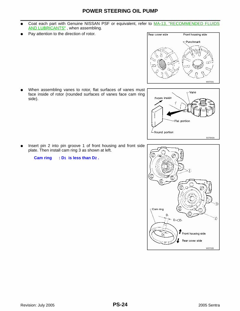
● Coat each part with Genuine NISSAN PSF or equivalent, refer to MA-13, "RECOMMENDED FLUIDSAND LUBRICANTS" , when assembling.
● Pay attention to the direction of rotor.
● When assembling vanes to rotor, flat surfaces of vanes mustface inside of rotor (rounded surfaces of vanes face cam ringside).
● Insert pin 2 into pin groove 1 of front housing and front sideplate. Then install cam ring 3 as shown at left.
WST031
SST843A
Cam ring : D1 is less than D2 .
WST035

HYDRAULIC LINE
PS-25
C
D
E
F
H
I
J
K
L
M
A
B
PS
Revision: July 2005 2005 Sentra
HYDRAULIC LINE PFP:49721
Removal and Installation EGS000JP
QG18DE Engine
WGIA0134E
1. Power steering fluid reservoir 2. Power steering pump 3. Steering gear
4. Tube 5. Hose 6. Washers
7. Power steering pressure sensor

PS-26
HYDRAULIC LINE
Revision: July 2005 2005 Sentra
QR25DE Engine
WGIA0135E
1. Power steering fluid reservoir 2. Power steering oil cooler 3. Power steering pressure switch
4. Steering gear 5. Power steering oil pump

SERVICE DATA AND SPECIFICATIONS (SDS)
PS-27
C
D
E
F
H
I
J
K
L
M
A
B
PS
Revision: July 2005 2005 Sentra
SERVICE DATA AND SPECIFICATIONS (SDS) PFP:00030
General Specifications EGS000G3
Steering Wheel EGS000G4
Steering Column EGS000G5
Steering Gear and Linkage EGS000G6
Applied model QG18DE QR25DE
Steering model Power steering
Steering gear type Rack and Pinion (PR25T)
Steering overall gear ratio 17.48 15.80
Turns of steering wheel (Lock to lock) 3.01 2.4
Steering column type Collapsible, tilt
Applied model All
Steering wheel axial play mm (in) 0 (0)
Steering wheel play mm (in) 35 (1.38) or less
Movement of gear housing mm (in) ±2 (±0.08) or less
Applied model All
Steering column length “L” mm (in) 542 - 544 (21.34 - 21.42)
SST855C
Applied model QG18DE QR25DE
Steering gear type Rack and Pinion (PR25T)
Tie-rod outer socket
Swinging force at cotter pin hole: “A” N (kg, lb) 6.9 - 65.7 (0.66 - 6.59, 1.5 - 14.8)
Rotating torque: “B” N·m (kg-cm, in-lb) 0.29 - 2.94 (3.0 - 30.0, 2.6 - 26.0)
Axial end play: “C” mm (in) 0.4 (0.016) or less
Initial tightening torque N·m (kg-cm, ft-lb) 29 - 39 (3 - 4, 22 - 28)
Maximum tightening torque N·m (kg-cm, ft-lb) 49 (5, 36)
Tie-rod inner socket
Swinging force*: “A” N (kg, lb) 5.9 - 46.1 (0.58 - 4.65, 1.3 - 10.4)
Axial end play: “C” mm (in) 0.2 (0.004) or less
Initial tightening torque N·m (kg-cm, ft-lb) 29 - 39 (3 - 4, 22 - 28)
Maximum tightening torque N·m (kg-cm, ft-lb) 49 (5, 36)
Tie-rod standard length “L” mm (in) 133.04 (5.238) 136.09 (5.358)
SST867C

PS-28
SERVICE DATA AND SPECIFICATIONS (SDS)
Revision: July 2005 2005 Sentra
*: Measuring point [l: 172 mm (6.77 in)]
Power Steering EGS000G7
Retainer adjustmentAdjusting screw
Initial tightening torque N·m (kg-cm, in-lb) 4.9 - 5.9 (50 - 60, 43 - 52)
Retightening torque after loosening N·m (kg-cm, in-lb) 0.2 (2, 1.7)
Tightening torque after gear has settled N·m (kg-cm, in-lb)
4.9 - 5.9 (50 - 60, 43 - 52)
Returning angle degree 60° - 80°
Steering gear type PR25T
Rack stroke “S” mm (in) 65 (2.56)
Pinion gear preload without gear fluidWithin ±100° from the neutral position
Average rotating torque N·m (kg-cm, in-lb) 0.6 - 2.0 (7 - 20, 6 - 17)
Maximum torque deviation N·m (kg-cm, in-lb) 0.6 (7, 5.8)
Except above rangeMaximum rotating torque N·m (kg-cm, in-lb) 1.9 (19, 17)
Maximum torque deviation N·m (kg-cm, in-lb) 0.65 (7, 6)
SST086BA
Applied model QG18DE QR25DE
Steering gear type Rack and Pinion (PR25T)
Pump type F40
Rack sliding force N (kg, lb)Under normal operating oil pressure
Range within ±11.5 mm (±0.453 in) from the neu-tral position at rack speed of 3.5 mm (0.138 in)/s
Average rack sliding force
210 - 325 (21.5 - 33.2, 47.4 - 73.2)
160 - 350 (16.3 - 35.7, 36.0 - 78.7)
Maximum force devia-tion
98 (10, 22)
Except for the above range
Maximum rack sliding force
294 (30, 66)
Maximum force devia-tion
147 (15, 33)
Steering wheel turning force(Measured at one full turn from the neutral position) N (kg, lb)
39 (4, 9) or less
Fluid capacity (Approximate) (US qt, Imp qt) 1.0 (1-1/8, 7/8)
Oil pump maximum pressure kPa (kg/cm2 , psi)7,649 - 8,238 (78 - 84,
1,109 - 1,194)8,000 - 8,800 (82 - 90,
1,160 - 1,276)