Embed Size (px)
Citation preview
1
PSERC
Automatic Slow Voltage Controllerfor Large Power Systems
Mani V. Venkatasubramanian
Washington State UniversityPullman WA
© 2003 – Washington State University, Pullman, WA
PSERC
2
Objectives
• Automatic switching of shunt capacitors, reactors, transformer taps, and generator high side voltages
• Maintain voltage profile• Minimize switching actions• Mitigate circular VAR flows• Reduce P and Q losses• Monitor voltage security• Alert ahead of unusual operating conditions
PSERC
3
Motivation
• Developed for western Oregon subsystem of Pacific Northwest operated by BPA
• Project funded by BPA and by CERTS through PSerc
• Doctoral thesis of Yonghong Chen, August 2001• Prototype implementation on-going since October
2001• National Systems and Research Co. (NSR) in
charge of implementation.• http://www1.nsrvan.com/avc
PSERC
4
Literature review
• Secondary voltage control in Europe: Divide into control areas and pilot point voltages
• OPF based control in Belgium: primarily for coordination of generator and shunt devices
• OPF based EMS scheme in PEPCO: optimal solution implemented by predefined control priorities
• Prior approaches designed for continuous controls. Discrete devices approximated.
PSERC
5
Western Oregon region
• Away from generators• Voltage control primarily by discrete devices• Capacitor/reactor banks, LTC transformers• Multiple banks at one bus• Close proximity of devices – strongly coupled.• Inherently a discrete control problem
PSERC
6
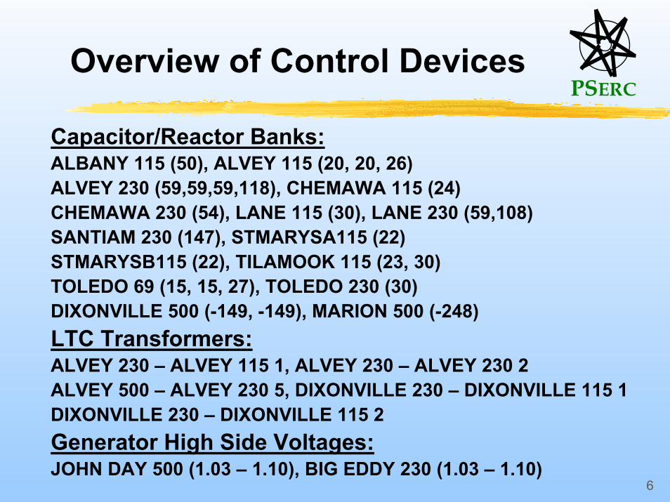
Overview of Control Devices
Capacitor/Reactor Banks:ALBANY 115 (50), ALVEY 115 (20, 20, 26)ALVEY 230 (59,59,59,118), CHEMAWA 115 (24)CHEMAWA 230 (54), LANE 115 (30), LANE 230 (59,108)SANTIAM 230 (147), STMARYSA115 (22)STMARYSB115 (22), TILAMOOK 115 (23, 30)TOLEDO 69 (15, 15, 27), TOLEDO 230 (30)DIXONVILLE 500 (-149, -149), MARION 500 (-248)LTC Transformers:ALVEY 230 – ALVEY 115 1, ALVEY 230 – ALVEY 230 2ALVEY 500 – ALVEY 230 5, DIXONVILLE 230 – DIXONVILLE 115 1DIXONVILLE 230 – DIXONVILLE 115 2Generator High Side Voltages:JOHN DAY 500 (1.03 – 1.10), BIG EDDY 230 (1.03 – 1.10)
PSERC
7
Present operation
• Visits to BPA Munro control center• Respond to voltage alarms and outages• Keep track of expected load changes and
switch early• Minimize number of switchings• Keep maximum devices in reserve• Avoid tap changes whenever possible• Avoid circulating VAR flows• Watch for bad data and false alarms
PSERC
8
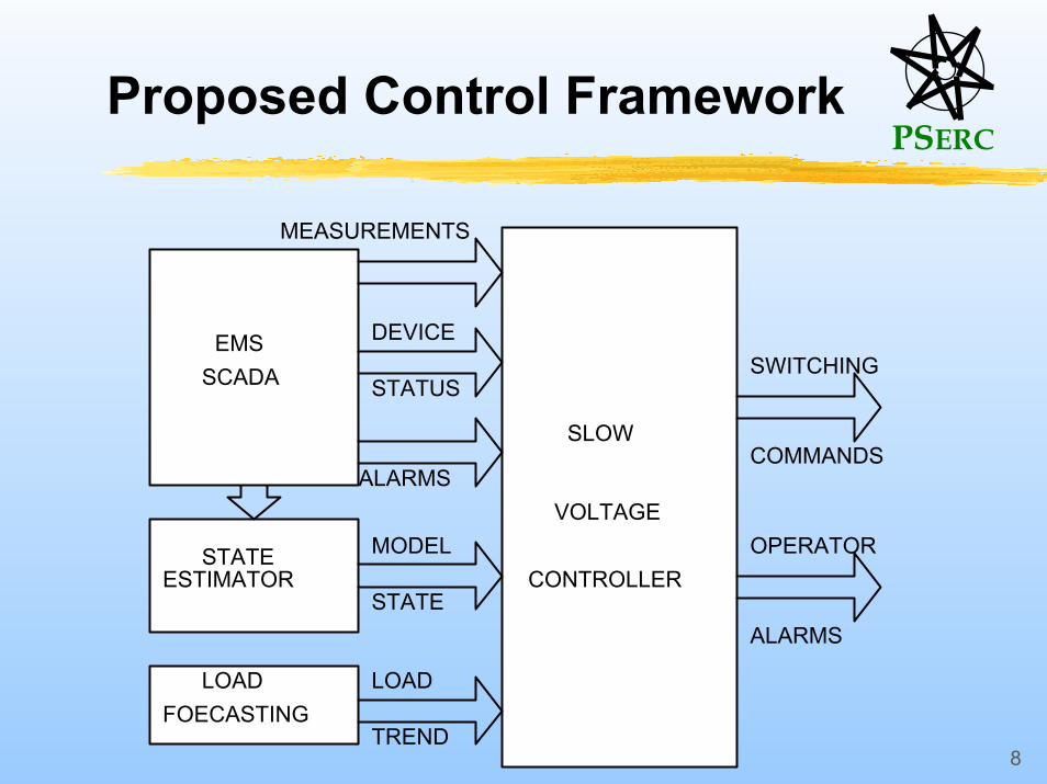
Proposed Control Framework
EMS
STATEESTIMATOR
MEASUREMENTS
ALARMS
MODEL
LOADFOECASTING
LOAD
STATE
SLOW
VOLTAGE
CONTROLLER
SWITCHING
COMMANDS
DEVICE
STATUSSCADA
TREND
OPERATOR
ALARMS
PSERC
9
Controller objectives
Present Formulation:• Maintain voltage profile• Minimize number of switchings• Maintain control preferences • Minimize circulating VAR flow
Future Formulation:• Minimize losses• Monitor voltage security
PSERC
10
Proposed Controller
• Nonlinear integer programming• Using adaptive local power-flow computations to
evaluate control effects• Multiple power-flow cases from load forecasting
considered in control decision• Circular VAR flow detection and minimization• Fast computation scalable to large systems• One switching at a time suggested• An approximate method for solving multiple
switchings
PSERC
11
}1,0,1{
||..
)],(),,([||
1
1 11,1
−∈
≤
++
∑
∑ ∑
=
= =
i
sw
n
ii
n
i
M
mnmcirnmmii
k
Nkts
kkgkkFpCkMin λ
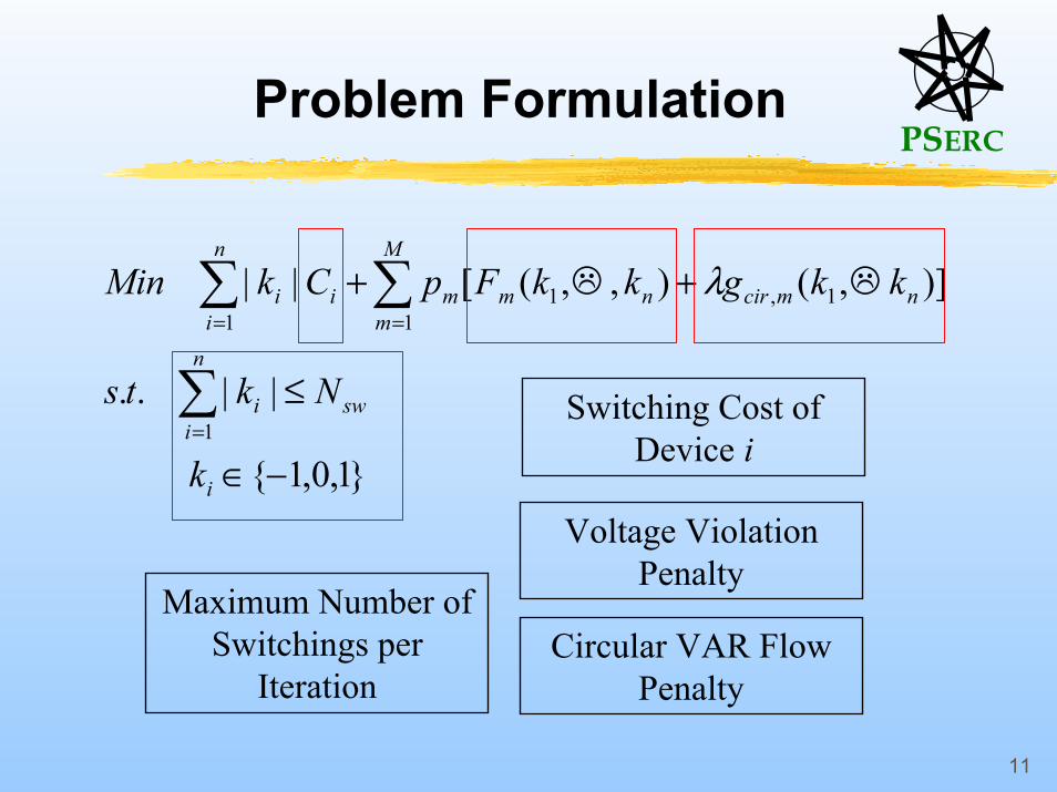
Switching Cost of Device i
Voltage Violation Penalty
Circular VAR Flow Penalty
Maximum Number of Switchings per
Iteration
Problem Formulation
PSERC
12
Cost Formulation
1) Switching cost of control device Ci :
Higher cost for switching in a device than switching outHigher cost for tap changers compared to capacitor and reactor banks Cost increases distinctly after one switching and decreases slowly afterwards
PSERC
13
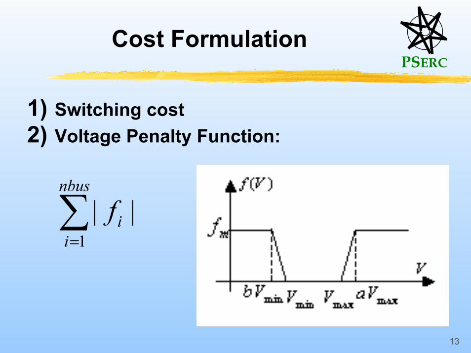
Cost Formulation
1) Switching cost 2) Voltage Penalty Function:
∑=
nbus
iif
1||
PSERC
14
Localized Computations
• Switching effect computed locally from adaptive localization.
• First keep only the buses within 10 tiers from the candidate control device.
• Calculate electric distance (ED) and leave out the buses with ED sufficiently large from the control device bus location.
• Leave out all the PV buses.• Repeat for other candidate devices.
PSERC
15
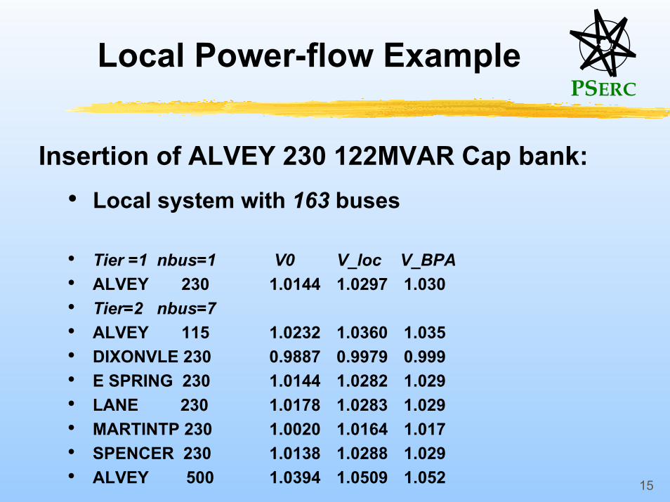
Local Power-flow Example
Insertion of ALVEY 230 122MVAR Cap bank:• Local system with 163 buses
• Tier =1 nbus=1 V0 V_loc V_BPA• ALVEY 230 1.0144 1.0297 1.030• Tier=2 nbus=7• ALVEY 115 1.0232 1.0360 1.035• DIXONVLE 230 0.9887 0.9979 0.999• E SPRING 230 1.0144 1.0282 1.029• LANE 230 1.0178 1.0283 1.029• MARTINTP 230 1.0020 1.0164 1.017• SPENCER 230 1.0138 1.0288 1.029• ALVEY 500 1.0394 1.0509 1.052
PSERC
16
Basic Optimization Procedure
Assume Nsw = 1 One switching at a time.
m = 1: One power-flow case:
• Find worst violation bus w.• Choose all control devices that have w in their
local systems.• Solve local power-flows and evaluate switching
effects and the device cost function• Switch the device with minimum cost
PSERC
17
Robust Optimization
• m > 1: Multiple power-flow cases:
m possible power flows, each with probability pi (i=1,…m). Find the control action that minimizes the weighted average of voltage penalty from multiple power-flows.
PSERC
18
Robust Optimization Example
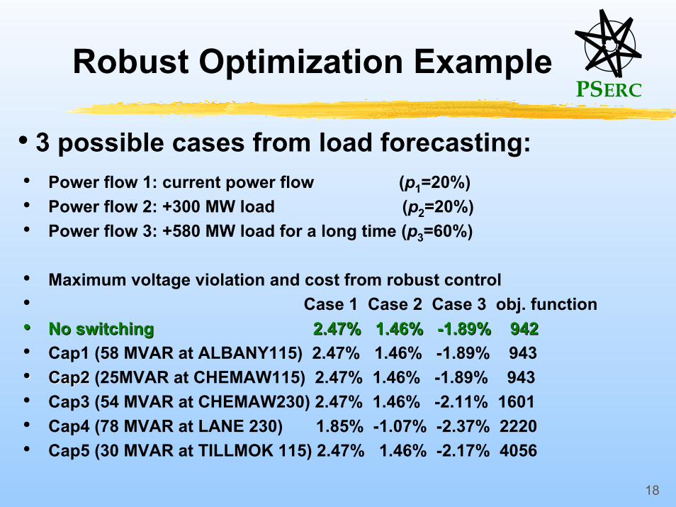
• 3 possible cases from load forecasting:• Power flow 1: current power flow (p1=20%) • Power flow 2: +300 MW load (p2=20%)• Power flow 3: +580 MW load for a long time (p3=60%)
• Maximum voltage violation and cost from robust control• Case 1 Case 2 Case 3 obj. function•• No switching No switching 2.47% 1.46% 2.47% 1.46% --1.89% 9421.89% 942• Cap1 (58 MVAR at ALBANY115) 2.47% 1.46% -1.89% 943•• Cap2 Cap2 (25MVAR at CHEMAW115) 2.47% 1.46% -1.89% 943• Cap3 (54 MVAR at CHEMAW230) 2.47% 1.46% -2.11% 1601• Cap4 (78 MVAR at LANE 230) 1.85% -1.07% -2.37% 2220• Cap5 (30 MVAR at TILLMOK 115) 2.47% 1.46% -2.17% 4056
PSERC
19
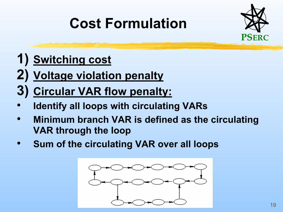
Cost Formulation
1) Switching cost2) Voltage violation penalty3) Circular VAR flow penalty:• Identify all loops with circulating VARs• Minimum branch VAR is defined as the circulating
VAR through the loop• Sum of the circulating VAR over all loops
PSERC
20
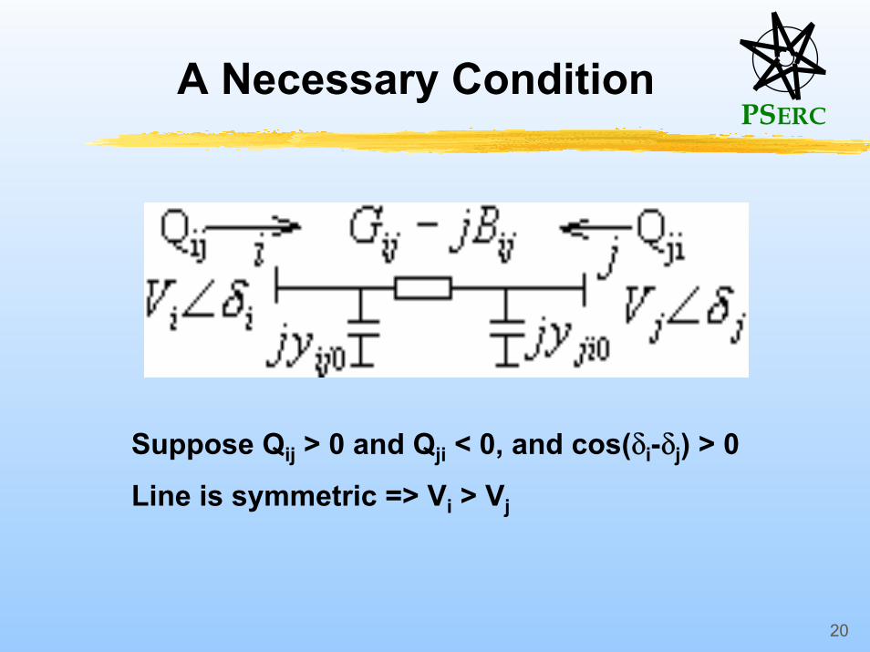
A Necessary Condition
Suppose Qij > 0 and Qji < 0, and cos(δi-δj) > 0Line is symmetric => Vi > Vj
PSERC
21
Circular VAR Flow Computation
• Necessary condition : At least one asymmetric line branch must be present in each circular VAR flow loop.
• Start with LTC transformer banks, lines with series compensation.
• Directed graph theory – depth first search.• Loops can be identified efficiently.
PSERC
22
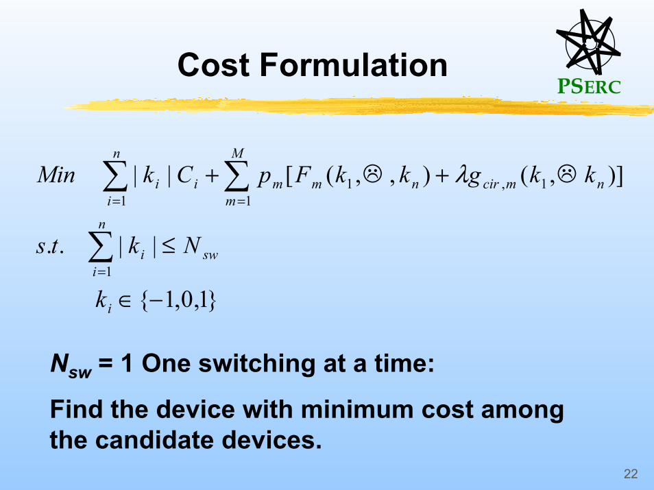
Cost Formulation
}1,0,1{
||..
)],(),,([||
1
1 11,1
−∈
≤
++
∑
∑ ∑
=
= =
i
sw
n
ii
n
i
M
mnmcirnmmii
k
Nkts
kkgkkFpCkMin λ
Nsw = 1 One switching at a time:
Find the device with minimum cost among the candidate devices.

PSERC
23
Multiple switching Nsw > 1
Approximate methods proposed.• Greedy algorithm
Always makes the choice that looks best at the moment. Quick suboptimal solutions for feasibility
• Dynamic programming / branch bounding method from linear approximation
sw
n
ii
n
iii
n
iii
Nk
VdVkVVts
CkMin
≤
≤⋅+≤
∑
∑
∑
=
=
=
1
max1
0min
1
||
..
||
PSERC
24
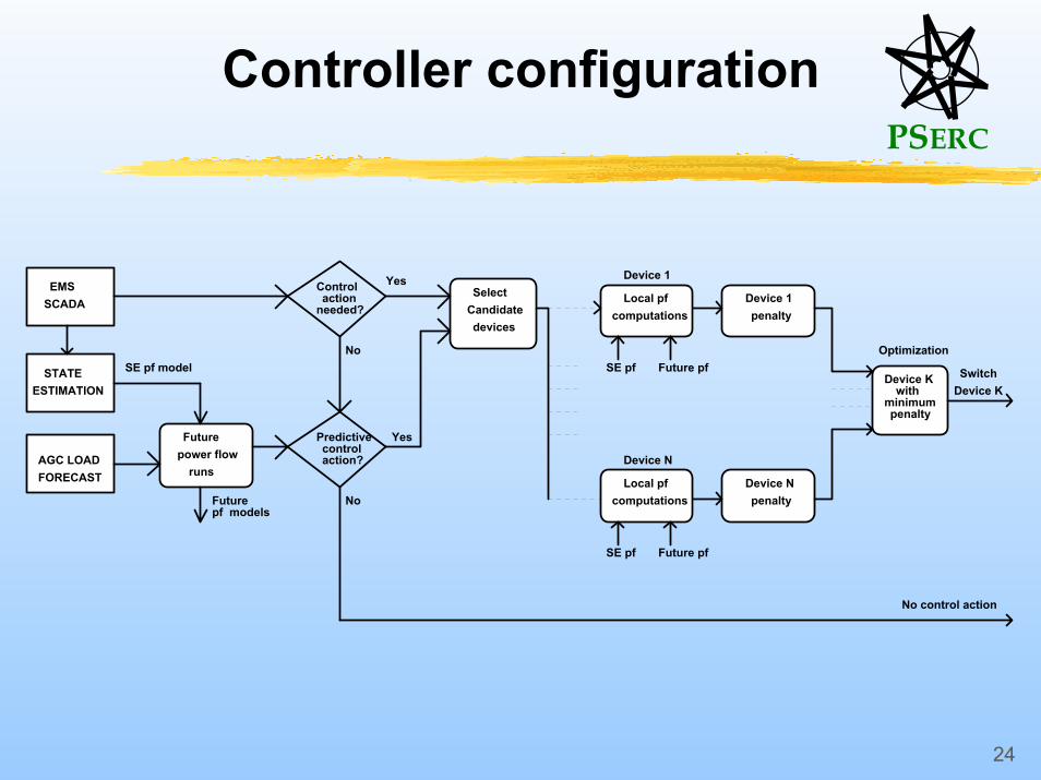
Controller configuration
EMSSCADA
STATEESTIMATION
AGC LOADFORECAST
SE pf model
Futurepower flow
runs
Futurepf models
Controlaction
needed?
Predictivecontrolaction?
Yes
No
Yes
No
SelectCandidatedevices
Local pfcomputations
Device 1
SE pf Future pf
Local pfcomputations
Device N
SE pf Future pf
Device 1penalty
Device Npenalty
Device Kwith
minimumpenalty
Optimization
SwitchDevice K
No control action
PSERC
25
Prototype Implementation
• National Systems and Research Co.- Ramu Ramanathan, V. Venkataramakrishnan,
Qinsheng Huang, …
• Bonneville Power Administration- Carson Taylor, Project Manager- Planning and operations engineers, operators
• Washington State University- Mani, Jing Dong Su
PSERC
26
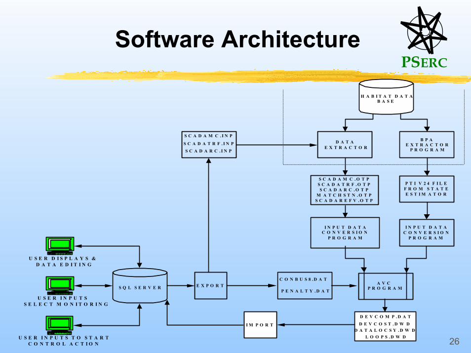
Software Architecture
A V CP R O G R A ME X P O R T
P T I V 2 4 F I L EF R O M S T A T EE S T I M A T O R
B P AE X T R A C T O R
P R O G R A M
U S E R I N P U T S S E L E C T M O N I T O R I N G
U S E R I N P U T S T O S T A R T C O N T R O L A C T I O N
U S E R D I S P L A Y S & D A T A E D I T I N G
S Q L S E R V E R
H A B I T A T D A T AB A S E
D A T AE X T R A C T O R
I M P O R T
I N P U T D A T AC O N V E R S I O N
P R O G R A M
I N P U T D A T AC O N V E R S I O N
P R O G R A M
S C A D A M C . I N P
P E N A L T Y . D A T
D E V C O S T . D W D
C O N B U S 8 . D A T
D E V C O M P . D A T
S C A D A T R F . I N P
D A T A L O C S Y . D W D
S C A D A R C . I N P
L O O P S . D W D
S C A D A M C . O T PS C A D A T R F . O T PS C A D A R C . O T P
M A T C H S T N . O T PS C A D A R E F V . O T P
PSERC
27
Implementation Status at NSR
• Web-based interface at http://www1.nsrvan.com/AVC• Developed the displays, interfaces with
SCADA and state estimator• Adopted AVC program to the entire BPA grid• Testing and tuning of the controller in
progress with input from BPA
PSERC
28
Current research at WSU
• Back-up heuristic controllers that run only from SCADA measurements.
• Device status, power-flows and voltages assumed known.
• Switching effects approximated.• Doctoral thesis of Jing Dong Su• Detection of bad data and false alarms• Large system considerations• Other capabilities.