Embed Size (px)
Citation preview

XVIII CONVEGNO ANIDIS
ASCOLI PI CENO 2 0 1 9L’ i ngegner i a si smi ca i n I t al i a
15- 19 Set t embre
Pseudo-Dynamic testing of existing steel frames with masonry infills:
assessment and retrofitting with BRBs
Luigi Di Sarnoa, Fernando Gutiérrez-Urzúab, Fabio Freddib, Mario D’Anielloc, Raffaele Landolfoc, Oh-Sung Kwond,
Stathis Bousiase, Matjaž Dolšek f, Jing-Ren Wu a, Maria Gabriella Castellanog a Dept. of Civil Eng. & Industrial Design, University of Liverpool, The Quadrangle, Brownlow Hill, L69 3BX, Liverpool, UK b Dept. of Civil, Environmental &Geomatic Eng., University College London, Gower St, WC1E 6BT, London, UK c Dept. of Structures for Eng. & Architecture, University of Naples Federico II, Via Forno Vecchio 36, 80134 Naples, Italy d Dept. of Civil and Mineral Eng., University of Toronto, 27 King’s College Cir, ON M5S, Toronto, Canada e Structures Laboratory (STRULAB), Civil Eng. Dept., University of Patras, 265 04, Patras, Greece f Faculty of Civil and Geodetic Eng., University of Ljubljana, Kongresni trg 12, 1000, Ljubljana, Slovenia g FIP Industriale, Via Scapacchiò 41, 35030, Selvazzano, Italy
Keywords: Existing steel frames, masonry infills, buckling restrained braces, seismic response, pseudo-dynamic tests
ABSTRACT
Many existing steel multi-storey frames in Europe were designed prior to the provisions of modern seismic design
codes; therefore, they often exhibit low resistance to earthquakes due to their insufficient energy dissipation capacity.
However, the current framework for assessing existing structures in EC8-3 is inadequate and should be reviewed.
Particular attention should be paid to the contribution from masonry infill walls as they significantly affect the modal
properties and the lateral stiffness of structures. To this end, the HITFRAMES (i.e., HybrId Testing of an Existing
Steel Frame with Infills under Multiple EarthquakeS) SERA project experimentally evaluates the seismic
performance of a case study structure representative of non-seismically designed steel frames in Europe including
the effects of the masonry infills. A retrofitted configuration of the structure, based on the use of Buckling Restrained
Braces, is also tested in order to provide information about the effectiveness of this type of devices. This paper
illustrates the preliminary analyses required for the design and assessment of the case study structure that will be
tested within the HITFRAMES SERA project. It attempts to simulate its non-linear behaviour to complement the
experiment design and to forecast the outcome of the tests. The sample building is assessed as a bare and infilled
frame under the EC8-3 framework by non-linear static analysis and comparisons are made between the two situations
to estimate the influence of the infills. Then, the retrofitted building is similarly assessed and comparison is made
with the original structure. Finally, non-linear time history analyses are performed on all the structural configurations.
The comparison allows to provide insights on the impact of the masonry infills and of the dissipative devices in the
numerical simulations and to critically discuss the drawbacks of the current version of the EC8-3.
1 INTRODUCTION
Modern seismic design codes consider the importance of the inelastic response of structures during an earthquake and provide detailed recommendations in order to ensure a ductile behaviour of the structural system, allowing the development of the energy dissipation capabilities. However, many existing steel-frame buildings were either designed prior to the provisions of modern seismic design codes or are located in zones recently reclassified as of medium-to-high seismicity and, therefore, were designed to comply with lower seismic demands, or not designed to comply with seismic demands at all. Those frames are often characterised by inadequate energy
dissipation capacity or even by a complete lack of a horizontal resisting system, amongst other deficiencies (e.g., those described in Di Sarno et al. 2018), leading to a high seismic vulnerability.
Post-earthquake reconnaissance surveys in the area hit by the 2016-17 Central Italy earthquakes, highlighted several failure modes on non-seismically designed steel frames including severe local damage and global collapse. Some failure modes were unexpected and strongly influenced by the presence of the masonry infills, which highlights the urgent need of a validated framework for assessing the seismic vulnerability of this kind of structures (e.g., Di Sarno et al. 2018; Araújo and Castro 2018).

Many code-based procedures for the assessment and retrofitting of existing steel frames have been developed so far, amongst others, the Eurocode 8 Part 3 (EC8-3) in Europe (European Committee for Standarization, 2005) and the ASCE 41 (Seismic Evaluation and Retrofit of Existing Buildings) in the United States, being the 2017 the most current version of the document (ASCE/SEI, 2017). Similarly to others, the latter codes generally adopt the performance-based earthquake engineering framework and allow the use of both linear and non-linear numerical simulation for the seismic assessment of existing structures. Nonetheless, a recent review of the EC8-3 by Araújo and Castro (2018) summarised some inconsistencies and limitations in the European code. For example, it has been observed that the use of different analysis methods suggested by the EC8-3 could lead to significantly different results in terms of demand estimations depending on the selected approach. Moreover, the capacity limits (CLs) for beam and column rotations for each Limit State (LS), are strongly inspired by the older version of American code ASCE 41-06 (ASCE/SEI, 2007), although the American codes refer to them as ‘acceptance criteria’. Those CLs were based on tests carried out on American steel profiles and could not be appropriate for the steel sections conventionally used in Europe. Additionally, EC8-3 requires safety checks of every individual member and define the onset of failure of a LS based on the first of those members exceeding the corresponding CL, neglecting the redundancy of a structure.
Given the current situation, a revision of EC8-3 is strongly needed to identify the potential areas of improvement to be included in the drafting of the next generation of European seismic assessment codes.
In addition, it is now widely accepted that the contribution of infill walls to the lateral stiffness and strength of steel frames could be significant and should be taken into consideration in assessment procedures (e.g., Di Sarno et al. 2018; Mohammad Noh et al. 2017; Uva et al. 2012; Dolšek and Fajfar 2008). In recent years, many authors focused on describing the behaviour of masonry infills allowing the definition of constitutive models. Several macro-models for masonry infills have been proposed and most of them, rely on the use of equivalent diagonal struts representing the masonry infill properties (e.g., Mohammad Noh et al. 2017; Fardis and Panagiotakos 1997; Asteris et al. 2013; Al-Chaar 2002; Elnashai and Di Sarno 2008). Macro-models have the advantage of reducing the required computational effort while allowing adequate
confidence in the assessment of the global response of the structure.
However, despite the large effort of the last few years, experimental and numerical studies on masonry infills (e.g., for the definition of infills’ macro-models and for the assessment of the influence of infills on the seismic response of the frame), focused mainly on reinforced concrete (RC) structures. This brings up the question regarding the possibility of using these models, calibrated in RC structures, in more flexible steel frames, and how the flexibility of the steel frames could influence the failure modes of the infills.
The present paper assesses the seismic performance of a case study steel Moment Resisting Frame (MRF) according to the procedure of the EC8-3, as preliminary work for experimental campaign of the HITFRAMES (i.e., HybrId Testing of an Existing Steel Frame with Infills under Multiple EarthquakeS) SERA Project. The results of the experimental tests will provide insights on the behaviour of infilled steel frame allowing also the calibration of numerical models.
The considered case study steel frame was designed to sustain gravity loads only by following the requirements of Eurocode 3 (EC3) (European Committee for Standarization, 2011). Moreover, it was designed with similar deficiencies to a steel frame in Amatrice that was damaged by the Central Italy earthquake sequence of 2016. This frame is widely investigated in literature (e.g., Di Sarno et al. 2018) and reported in Figure 1. A 3D structural model was implemented in OpenSees (Mckenna et al. 2010) and non-linear static and dynamic analyses were performed to estimate the seismic demand for each limit state. Special attention was paid to the contribution of masonry infills to the overall performance of the frame.
Figure 1. Amatrice building that was used as a base for the experimental sample. See Di Sarno et al. (2018).

2 ‘HITFRAMES’ EXPERIMENTS
OUTLINE
The case study selected for the experimental campaign is a two-storey, three-bays by one-bay non-seismically designed steel framed with masonry infills as reported in Figure 2. The structural system is constituted by a 3D MRF, however, the resistance and the stiffness of the joints are not guaranteed, since their design was carried out on the basis of the elastic forces due to gravity loads only. In addition, the weak beam-strong column hierarchy was not fulfilled, especially in the internal joints where the flexural continuity of the beam is generally provided in the weak axis of the column. This is consistent with the case study presented by Di Sarno et al (2018).
These drawbacks have been properly introduced in the designed mock-up building, in order to experimentally simulate the deficiencies of the system as well as a possible retrofitting technique.
The HITFRAMES project involves two main phases. In both phases the structure is tested under an horizontal load in the X direction as indicated in Figure 2. In the first phase, the case study structure will be tested considering a 75% scaled 3D model of the frame. The test will be performed with a hybrid approach in which only the central bay of the structure will be physically represented by the lab specimen, while the rest of the structure is simulated numerically. The specimen will be first subjected to a modal characterisation process through a ‘snap back’ test and low-amplitude ground motions, for the bare and infilled configurations, in order to allow the calibration of the numerical models. Successively, the structure will be subjected to an incremental pseudo-dynamic test under recorded mainshock-aftershock sequences up to collapse. Amongst others, the study will allow to identify the effect of the stiffness and strength degradation on both the structural and non-structural components on the seismic performance of the system.
In the second phase, the same testing procedure will be used on a 75% scaled 2D model of the frame. In this case, only one frame of the central bay of the system will be physically represented by the lab specimen. The specimen will be initially characterised for the modal parameters considering both the bare and infilled configurations. Successively, the steel frame will be retrofitted with Buckling Restrained Braces (BRBs) and the characterisation phase will be performed again on the retrofitted frame. The ‘three phases’ characterization procedure allows to independently calibrate the stiffness of the
different components of the physical specimen allowing to gain confidence on the elastic behaviour of the numerical models. After this, as for the previous phase, the retrofitted frame will be subjected to incremental pseudo-dynamic tests within an hybrid simulation approach. This will allow to study the impact of the retrofitting scheme including the effectiveness of the BRB elements when they are used to retrofit infilled steel frames, and their capacity to protect both structural and non-structural components. Scaling was made in an equal-stress basis to be able to keep the material properties constant for both buildings (full and 75% scaled), therefore, the rest of the characteristics of the building were reduced by a factor of λ or an exponential value of it. A summary with the scaling rules followed for the physical specimen can be found in Table 2. Details on the equivalency between steel profiles from the full scale to the scaled building can be found in Table 1.
As mentioned before, this building was designed by considering only gravity loading, therefore, only EC3 was used as the design code. Similar deficiencies of the Amatrice building were included, e.g., columns resisting lateral loads on the profile’s weak axis, strong-beam weak-column and soft storey mechanisms.
The floor system was designed as a composite slab, with a cold-rolled steel sheet base (SYMDECK 73 t = 1.25 mm) and a 13 cm deep concrete slab with M19 shear studs at each valley or at 300 mm, depending on the steel sheet ribs orientation.
Table 1. Steel profiles for the prototype and scaled structures.
Element Steel profiles
Full scale 75% scaled
Columns HE 240 A HE 180 A
Primary beams IPE A 270 IPE A 200
Secondary beams IPE A 200 IPE A 140
Table 2. Scaling factors. = 0.75.
Parameter Scaling
factor
Stress, density, strain, angular deformation
and acceleration
λ0 = 1
Period, time and velocity λ1/2 = 0.87
Length, linear deformation and stiffness λ1 = 0.75
Force, weight, mass and area λ2 = 0.56
Volume, section moduli and moment λ3 = 0.42
Moment of inertia λ4 = 0.32

Figure 2. Prototype building global geometry (in millimetres), plan view (top left), and elevations.
The distribution of shear studs provides a load
path for the earthquake input which is uniformly distributed from the actuators onto the steel structure; however, shear studs were not installed in the regions of the beam-to-column connections, to ensure the uninfluenced response of the steel bare joints.
Even though the masses can be numerically simulated in the hybrid pseudo-dynamic test, concrete blocks are required to simulate the additional gravity loads on columns and beams, since these loads have an influence on the plastic rotation of the columns and the asymmetrical moment and shear diagrams on the beams. This additional gravity loads were calculated to be representative of the non-structural permanent loads and the transient loads. For the 3D tests, 12.5 ton and 10.15 ton additional masses will be located on the first and second floors, respectively. In addition, masses of 1.012 ton and 0.506 ton will be added on the first and second storeys, respectively, to represent the load of the masonry infills while
characterising the dynamic behaviour of the bare frame. These last masses will be removed when the masonry wall is built. For the 2D test, only half of the masses will be kept.
3 ASSESSMENT FRAMEWORK OF EC8-3
3.1 Hazard level and Limit States
The assessment procedure of steel frames according to the EC8-3 and based on the non-linear analysis procedure is briefly described in this section. The procedure according to linear analysis methods is not considered in this study.
Although the assessment was done according to the Eurocodes, a comparison has been made with the newer ASCE 41-17 in an attempt to identify the possible improvement areas and future development paths for the European code. However, a detailed comparison of the codes is

beyond the aim of this paper and only few aspects are discussed.
The EC8-3 proposes three LSs: Damage Limitation (DL), Significant Damage (SD), and Near Collapse (NC). These LSs are qualitatively described for both structural and non-structural elements. The structural descriptions for the LSs from EC8-3 are very similar to the three basic LSs from the ASCE 41-17 (Immediate Occupancy, Life Safety and Collapse Prevention), which allows to pair them as equivalent, at least in qualitative terms.
However, when considering the hazard level related to each LS, the approach is significantly different. The EC8-3 provides specific hazard levels for each LS, differently, the ASCE 41-17 allows more flexibility. In fact, the American code suggests that the decision should be made based on the specific performance needs of the design and leaves to the designer, in consultation with the owner of the building, the freedom to decide the hazard level for each LS in agreement with the performance based earthquake engineering philosophy. This is understandable since the European code is an official regulation while the American one is a non-mandatory guideline.
Another aspect to consider is that the hazard levels required in EC8-3, differ from those used in Eurocode 8 Part 1 (EC8-1) (European Committee for Standarization, 2004) for the design of new buildings and the design of retrofitting schemes. Table 3 shows the return period related to each LS compared to those required for new constructions.
Table 3. Return periods for different Limit States
Code Limit State Return period,
TR
[ years ]
EC8-3 Damage Limitation 225
Significant Damage 475
Near Collapse 2475
EC8-1 Damage Limitation State 95
Ultimate Limit State 475
As it can be seen, the hazard level
corresponding to the SD LS is the same than the one used for designing new structures or retrofitting by using EC8-1. It is interesting to notice that the Ultimate Limit State (ULS) in EC8-1, despite its name, is equivalent to the SD LS in EC8-3 in terms of hazard level and very similar in qualitative description, while the NC LS is generally assumed to be closer to the real collapse of the structure and is associated with a much longer return period. The explanation given in the code is that NC LS makes full use of the deformation capacity of structural elements
without reaching collapse, while the ULS and SD LS allow large plastic deformation as long as it does not compromise life, for example, by restricting the walls out-of-plane failure and by keeping enough lateral stiffness to withstand aftershocks.
This rough equivalency between the ULS from EC8-1 and the SD LS from EC8-3 is a good picture of the philosophy under which the assessment code was created: to bring up existing structures to performances similar to the expected from new structures. This is in contrast with the philosophy of American regulations, in which the reference performance objectives for existing structures (such as the Basic Performance Objective for Existing Structures, BPOE) is less conservative than the desired performance objectives for new structures (such as the Basic Performance Objective for New Structures, BPON).
Although both Damage Limitation State (DLS) from EC8-1 and DL LS of EC8-3 have similar names, they differ in the qualitative definition and in return periods. While DL LS is described as a structure with elastic behaviour and no structural repairs needed, the DLS is aimed to avoid all damage and indirect losses and to guarantee the elastic behaviour of the whole building, including non-structural elements. This difference is consistently reflected in the return periods related to each LS.
3.2 Knowledge level
The EC8-3 also provides some guidance on the data collecting of existing buildings, where information of geometry, detailing and materials should be gathered. Three knowledge levels are considered to deal with the uncertainties during the process of surveying, from limited to full knowledge level. A confidence factor is assigned to each knowledge level, which is used in the assessment of capacity as a partial safety factor. For the purpose of this study, full knowledge is assumed, thus a confidence factor of 1.0 is taken and no reduction is required in the safety verification.
3.3 Capacity Limits
Safety checks based on the comparison between the demand and capacity values is the last stage in the assessment framework of EC8-3. In this phase of the assessment procedure, the EC8-3 suggests to monitor different engineering demand parameters depending on if the checks involve ductile or brittle structural elements. When using the non-linear analysis approach, as suggested by the Eurocodes, the global demand parameters can
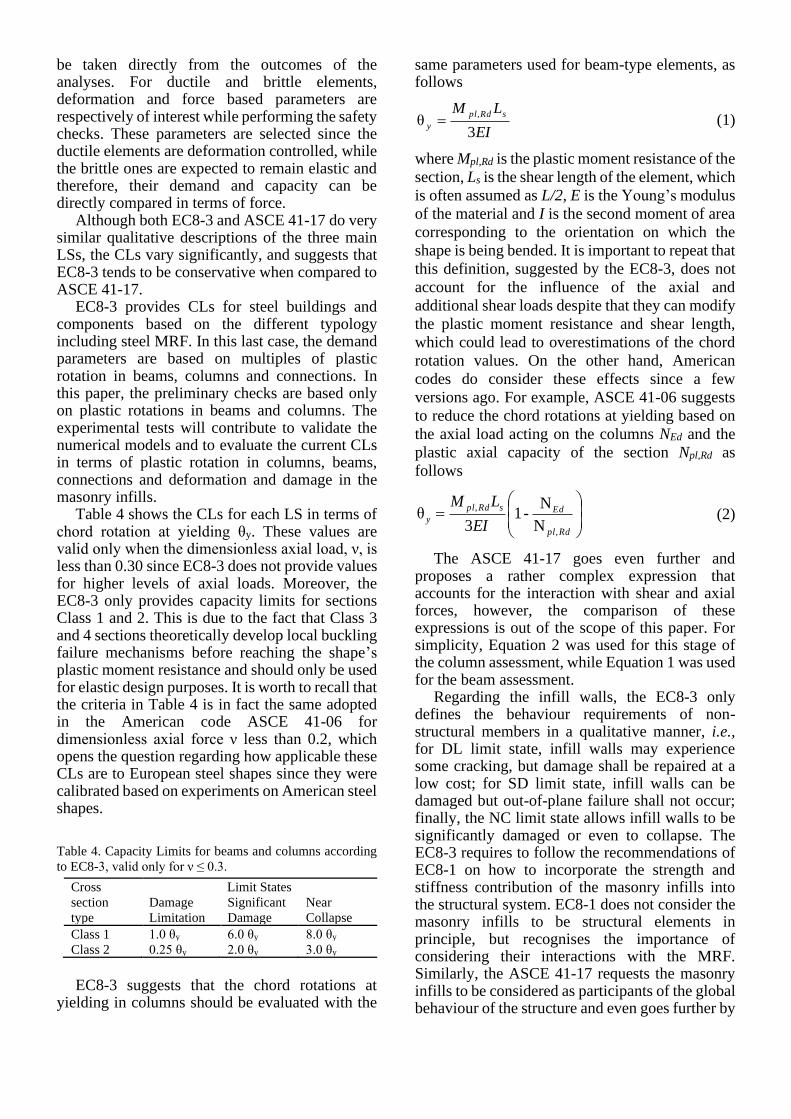
be taken directly from the outcomes of the analyses. For ductile and brittle elements, deformation and force based parameters are respectively of interest while performing the safety checks. These parameters are selected since the ductile elements are deformation controlled, while the brittle ones are expected to remain elastic and therefore, their demand and capacity can be directly compared in terms of force.
Although both EC8-3 and ASCE 41-17 do very similar qualitative descriptions of the three main LSs, the CLs vary significantly, and suggests that EC8-3 tends to be conservative when compared to ASCE 41-17.
EC8-3 provides CLs for steel buildings and components based on the different typology including steel MRF. In this last case, the demand parameters are based on multiples of plastic rotation in beams, columns and connections. In this paper, the preliminary checks are based only on plastic rotations in beams and columns. The experimental tests will contribute to validate the numerical models and to evaluate the current CLs in terms of plastic rotation in columns, beams, connections and deformation and damage in the masonry infills.
Table 4 shows the CLs for each LS in terms of chord rotation at yielding θy. These values are valid only when the dimensionless axial load, ν, is less than 0.30 since EC8-3 does not provide values for higher levels of axial loads. Moreover, the EC8-3 only provides capacity limits for sections Class 1 and 2. This is due to the fact that Class 3 and 4 sections theoretically develop local buckling failure mechanisms before reaching the shape’s plastic moment resistance and should only be used for elastic design purposes. It is worth to recall that the criteria in Table 4 is in fact the same adopted in the American code ASCE 41-06 for dimensionless axial force ν less than 0.2, which opens the question regarding how applicable these CLs are to European steel shapes since they were calibrated based on experiments on American steel shapes.
Table 4. Capacity Limits for beams and columns according
to EC8-3, valid only for ν ≤ 0.3.
Cross
section
type
Limit States
Damage
Limitation
Significant
Damage
Near
Collapse
Class 1 1.0 θy 6.0 θy 8.0 θy
Class 2 0.25 θy 2.0 θy 3.0 θy
EC8-3 suggests that the chord rotations at
yielding in columns should be evaluated with the
same parameters used for beam-type elements, as follows
EI
LM sRdpl
y3
θ,
= (1)
where Mpl,Rd is the plastic moment resistance of the
section, Ls is the shear length of the element, which
is often assumed as L/2, E is the Young’s modulus
of the material and I is the second moment of area
corresponding to the orientation on which the
shape is being bended. It is important to repeat that
this definition, suggested by the EC8-3, does not
account for the influence of the axial and
additional shear loads despite that they can modify
the plastic moment resistance and shear length,
which could lead to overestimations of the chord
rotation values. On the other hand, American
codes do consider these effects since a few
versions ago. For example, ASCE 41-06 suggests
to reduce the chord rotations at yielding based on
the axial load acting on the columns NEd and the
plastic axial capacity of the section Npl,Rd as
follows
N
N-1
3θ
,
,
=
Rdpl
EdsRdpl
yEI
LM (2)
The ASCE 41-17 goes even further and proposes a rather complex expression that accounts for the interaction with shear and axial forces, however, the comparison of these expressions is out of the scope of this paper. For simplicity, Equation 2 was used for this stage of the column assessment, while Equation 1 was used for the beam assessment.
Regarding the infill walls, the EC8-3 only defines the behaviour requirements of non-structural members in a qualitative manner, i.e., for DL limit state, infill walls may experience some cracking, but damage shall be repaired at a low cost; for SD limit state, infill walls can be damaged but out-of-plane failure shall not occur; finally, the NC limit state allows infill walls to be significantly damaged or even to collapse. The EC8-3 requires to follow the recommendations of EC8-1 on how to incorporate the strength and stiffness contribution of the masonry infills into the structural system. EC8-1 does not consider the masonry infills to be structural elements in principle, but recognises the importance of considering their interactions with the MRF. Similarly, the ASCE 41-17 requests the masonry infills to be considered as participants of the global behaviour of the structure and even goes further by

proposing numerical CLs (acceptance criteria) for these elements.
4 ASSESSMENT APPLIED TO HITFRAMES
PROJECT
The prototype building was evaluated by using the OpenSees platform (Mckenna et al. 2010) for two different cases:
- Case A, Bare frame - Case B, Infilled frame
4.1 Modelling details
Columns are modelled with a distributed plasticity fibre-based approach with ten integration points and Steel01 material with 2% hardening. On the other hand, beams are modelled as elastic elements with lumped plasticity at their ends to represent the plastic hinges formation. The whole beam system is modified according to Zareian and Medina (2010) to avoid the duplicity of flexibility and damping due to the lumped plasticity configuration. ZeroLength elements are used for the plastic hinges and their moment-rotation relationships are calibrated according to Lignos and Krawinkler (2011). Figure 3 shows the backbone curve for the calibrated plastic hinges with initial stiffness modified by a factor of n = 10.
Figure 3. Backbone curve of the calibrated plastic hinges
Connections are modelled as fully rigid due to
the presence of stiffeners placed in the beam-column joints, and considering that the panel zone deformability is not included since the beams are connected on the columns’ web on the columns weak direction.
Although several masonry infill models are available in literature, most of them have been
developed for infills walls to be used within RC frames (e.g., the models used by Mohammad Noh et al. 2017; Liberatore et al. 2018; Decanini and Fantin 1986; Crisafulli and Carr 2007; Dolšek and Fajfar 2008; Uva et al. 2012) and it is unclear to what extent these models can be used to represent masonry struts in more flexible steel frames. However, due to the lack of specialised models for steel structures, the material model developed by Decanini and Fantin (1986) and more recently used by Liberatore and Decanini (2011) and Mohammad Noh et al. (2017) is used in this study.
The selection of this model was based on its simplicity, however, it is yet unclear which one describes the masonry strut within a steel frame more accurately. Then, the model is further simplified into a single strut on each direction since the main interest at this stage of research is to understand the overall behaviour of the structure rather than the modelling of a more accurate masonry strut material. This is also consistent with the flexible nature of the tested frame, that is expected to cause the masonry-frame contact zones to be concentrated in the corners. The material properties used in the current models correspond to the theoretical values used by Mohhammad Noh et al. (2017).
Figure 4 shows the masonry strut constitutive law employed in this study and its comparison with other models proposed in literature, all of them based on the first storey geometry. It is worth to note that there is a significant discrepancy between these models and, therefore, preliminary tests on the infills will be carried out within the experimental campaign in order to increase the confidence on the numerical models that will be employed in the hybrid tests. The backbone curves in Figure 4 represent one 7.8 cm layer of masonry, however, the specimen has two layers of masonry separated by an insulating layer, therefore, those values should be multiplied by two for each direction of each infill panel. A residual capacity of 10% the peak strength was included for the behaviour of the struts in tension in order to avoid numerical convergence issues. It is still unclear how the damage accumulation on one masonry strut direction affects the strength and stiffness of that same wall panel when it is pushed on the other direction, however, some masonry infill models (i.e., Rodrigues et al. 2010) consider a single spring with concentrated plasticity to represent deformation in both directions and, therefore, the damage cumulated in the spring affects the structure independently of the storey drift direction. The experimental campaign will help to shed light also on this aspect.

Figure 4. Backbone curve for masonry infill struts based on the material model proposed by Decanini and Fantin (1986), compared to models proposed by Dolšek and Fajfar (2008) and Crisafulli and Carr (2007).
4.2 Modal characteristics of the structure
Both cases are analysed only in the X direction (see Figure 2). Therefore, all the modal properties reported below correspond to analyses in the X axis. This was decided based on the damage observed in the Amatrice building and the lab resources available. In order to define the dynamic properties of the building only the masonry struts in one direction are introduced in the numerical model to avoid the duplicity of the initial stiffness. Table 5 provides details on the modal characteristics of the prototype building for the bare (Case A) and infilled (Case B) configuration. The results show that the infills have an important influence on the dynamic behaviour of the structure. It is worth to mention that the quick stiffness and strength degradation of the masonry infills also contributes to the continuous change in modal characteristics of the building, which means that the Case B structural periods will be changing while the masonry is being damaged and will become closer to the modal results for Case A.
4.3 Non-linear static analysis
The non-linear static analysis (i.e., pushover) is
performed according to the two lateral load
patterns conventionally used in literature and
recommended by the Eurocodes (European
Committee for Standarization, 2004). These are:
1. the “modal” pattern where the horizontal
loads are proportional to the first mode
shape.
2. the “uniform” pattern where the horizontal
loads are proportional only to the masses;
Table 5. Modal characteristics of the prototype building
Case 1st mode
period, T1
[ sec ]
2nd mode
period, T2
[ sec ]
1st mode
shape
Case A 0.902 0.333 [0.46, 1]
Case B 0.108 0.044 [0.56, 1]
It was found that, for this specific building, the
pushover curves for the modal and uniform lateral load distributions are almost identical, with slightly higher deformations on the modal distribution. Figure 5 shows the pushover curves for both cases and both load patterns. In Case A, the curves correspond to a typical ductile MRF behaviour. Differently, in Case B the masonry infills provide a significant increase in terms of initial stiffness and base shear. The infills behave elastically and hence provide a large increase of the initial stiffness of the frame until a global drift ratio of 0.08%. After this point, the infill of the first floor starts losing resistance and the whole frame decreases its stiffness, but continues to increase its overall resistance due to the contribution of the steel frame and the second floor masonry strut. The infilled frame reached its maximum base shear for a global drift ratio of about 0.8% and eventually, the total loss of masonry infills contribution at all storeys takes the frame to a similar behaviour of the one of the bare frame when a 3% drift is achieved. It is important to highlight that these curves have an infinite deformation capacity, which means that the building collapse is not yet considered.
Regarding the failure mechanism, it is observed that most damage is concentrated in the first storey, which is consistent with the uniform stiffness of the building and the increasing shear on each subsequent level, as can be observed in Figure 6. However, it is worth noticing that the storey drift concentration occurs at about 2.5% of global drift ratio for the Case A, while it is practically always present for Case B. This means that the masonry struts are not only modifying the strength and stiffness of the building, but also are inducing a much earlier soft storey mechanism. This can be explained by the increase on the second storey stiffness, which after the first storey strut failure, will behave similarly to the first level, until the force applied on the second storey is big enough to make its strut fail.
This is probably not a realistic behaviour, since the original lateral forces are calibrated based on the modal pattern, which takes into account the first mode shape. However, as soon as the first floor struts fail, it will change the first mode shape and tend to a uniform distribution (like an inverted pendulum made of two entire slabs with the

deformation concentrated in the first floor columns), increasing the amount of proportional load taken by the first storey alone to reach the same displacement and inducing a storey drift concentration. Therefore, the use of a more detailed approach, such as the adaptive pushover analysis (Antoniou and Pinho, 2004; Pinho et al., 2013) could be beneficial to evaluate the Case B.
4.4 Performance assessment based on EC8-3
This section shows the performance checks based on the comparison of the demand and capacity for the rotations in beams and columns and for the IDRs. Chord rotation at yielding in beams and columns were calculated by using Equations 1 and 2, respectively, and the LSs were evaluated with the CLs from Table 4. The IDR was calculated directly as the horizontal inter-storey deformation over the storey height. Since there are no CLs in EC8-3 for IDR, the limits proposed based on the Structural Engineers Association of California’s Blue Book (SEAOC, 1996), which were set to 1, 2.5 and 4% for the DL, SD and NC LSs, respectively.
The LSs placed on the pushover curve can be observed in Figure 7. The green, orange and red colours represent the DL, SD and NC LSs, respectively. The triangles represent the CLs related to the yield rotation of the columns, while the circles represent the CLs related to the IDR. For this specific frame, plastic hinges on beams were not developed, due to the large stiffness ratio between the beams and the columns. Table 6 shows a detailed summary of the CLs for each LS, in terms of global drift ratio.
As expected, it can be observed that the infilled
frame (Case B) develops both CLs in all LSs
earlier than the bare frame, due to the softening of
the first storey masonry struts, which causes a soft
storey mechanism. It can also be observed that by
the time the Case B curve becomes parallel to Case
A curve, the building has already overpassed the
NC LS, which suggests that the Case B structure
would collapse before reaching a similar
behaviour to Case A structure.
Table 6. Detailed numerical Capacity Limits for each Limit
State, in terms of global drift ratio
Case Capacity Limits Global drift ratio [ % ]
DL SD NC
Case A IDR 1.29 3.01 4.42
Columns 0.51 2.87 3.81
Case B IDR 0.69 1.71 2.64
Columns 0.20 1.50 2.09
Figure 5. Pushover curves for Cases A and B
Figure 6. Inter-storey drift ratios comparison for modal pattern distribution
Figure 7. Pushover curves with capacity for each Limit
State

Figure 8. Bilinear capacity curves and hazard demand in Acceleration-Displacement Response Spectrum plane, for Case A (left), Case B (centre) and Case B-R (right)
The Type 1 elastic response spectrum for
ground type B of the EC8-1 is assumed for the definition of the demand. The peak ground accelerations (PGA) are considered equal to 0.1975g, 0.25g and 0.4275g respectively for the DL, SD and NC LS. PGA values are defined according to the seismicity of Central Italy based on the seismic zonation map of the INGV (i.e., Istituto Nazionale di Geofisica e Vulcanologia) (e.g., Montaldo et al., 2007).
The comparisons of the demand vs capacity, required for the performance checks, are made according to the N2 method (Fajfar, 2000), as recommended by the EC8-1. In the N2 method, the frame is represented by an equivalent Single Degree of Freedom (SDoF) system which behaviour is idealised by an equivalent bilinear curves. This method is widely accepted, however, it presents some drawbacks when checks are
performed for the DL LS, which is expected to happen within the linear-elastic region, or for the assessment of infilled frames, which capacity curve cannot be directly simplified into a bilinear model.
Dolšek and Fajfar (2004, 2005) proposed a modification to the N2 method (IN2 method) to account for the influence of infill walls in RC structures, which considers the impact of the strength and stiffness provided by the infills, and proposed a multi-linear curve that characterises better the typical infilled frame capacity curve. Additionally, they proposed equations to define the R-μ-T relationship to derive the inelastic spectra. At this stage, the N2 method was used for all cases for simplicity reasons. For the Case B, the bilinearised capacity curve is based on the contribution of the steel structure only, while the displacement limits for each LS are based on the

results from the non-linear infilled frame pushover analysis. This simplification is expected to underestimate the real strength and ductility capacity the real structure, therefore, it is used only as a reference.
Figure 8 shows the comparison of demand and capacity for the Case A for the different LSs by using the N2 method. It can be observed that the capacity curves for the DL and NC LSs do not meet the design demand, while the capacity curve for SD does. This figure also shows demand vs capacity for Case B, in which the demand is not met for any of the LSs. As mentioned before, this is unlikely to be the case since the simplifications made are rather conservative.
Although the N2 method cannot satisfactorily be used to compare both cases, it can be observed that in Case B, the infills cause an earlier development of plastic hinges (in terms of global drift). The main source of initial stiffness comes from the infills, which quickly degrade and this makes the structure behave similarly to the bare frame from Case A.
When the steel structure in Case B is compared to the bare frame from Case A (Figure 9), it is found that structure B develops higher demands on the steel structure at the same levels of global drift. This is explained due to the high stiffness of the second storey which still possess an almost undamaged masonry strut, which makes the first floor to be the main contributor of the global drift. This interpretation is consistent with the lower capacity of Case B building expressed before.
Figure 9. Contribution of infills and steel frame to the
overall resistance of the first storey for Case B
5 ASSESSMENT OF THE RETROFIT
SCHEME
As part of the HITFRAMES project, the case study building will be retrofitted with BRBs to assess the improvement in the structural system behaviour and to study to what extent the braces can protect the masonry infills. Therefore, a design proposal was made based on the results of the numerical analyses.
BRBs are devices that are capable of withstanding both tension and compression in an almost symmetrical way. A sleeve protects the core brace from buckling, therefore, the core brace is capable of developing yield stresses in both directions. This almost symmetric behaviour makes them a convenient dissipating device and, therefore, their use is widespread across multiple research projects (i.e., Freddi et al. 2013; Di Sarno and Manfredi 2010, Di Sarno and Manfredi 2012).
5.1 Retrofit design process
According to EC8-3 the retrofitting must be designed in order to meet the standards of a new structure (i.e., by using EC8-1). The design was performed by considering both the ‘lateral force method of analysis’ and the ‘modal response spectrum analysis’. Due to the high influence of the first mode in the overall behaviour of the structure, both results were very similar.
The resulting design is based on four BRBs in the X direction, two per storey. They are located at both sides of the central span, as observed in Figure 10. Since the BRBs will be installed in the physical specimen for the tests, they were designed for the 75% scaled structure and then de-scaled for the full size models for the assessment process. Devices BRAD labelled as 21/40-b and manufactured by FIP Industriale are chosen for the retrofitting. They possess a yielding resistance of 143 kN for a 2.02 mm displacement, which increases up to 178 kN due to the kinematic hardening. The device has an ultimate resistance of 210 kN at 20 mm displacement. They have a length of 1.585 m and are arranged in series with a steel brace designed to remain elastic and to avoid buckling under the ultimate resisting force that the connected BRB can develop. The steel brace is made with a 160 mm diameter, 10 mm thickness round tubular section with steel S355. In the numerical model, the BRB devices and elastic braces were modelled as two axial-only elements working in series. The BRB devices were modelled based on the model proposed by Zona and Dall’Asta (2012) by using the OpenSees material ‘steelBRB’, while the braces were modelled as elastic elements.

Figure 10. Location of Buckling Restrained Braces in
elevation X-X’
Figure 11. Pushover curves with capacity for each Limit
State for retrofitted structures
Figure 12. Contribution of infills and steel frame to the
overall resistance of the first storey for Case B-R
Table 7. Modal characteristics of the retrofitted full scale
building
Case 1st mode
period, T1
[ sec ]
2nd mode
period, T2
[ sec ]
1st mode
shape
Case A-R 0.5106 0.2032 [0.5440, 1]
Case B-R 0.1063 0.0431 [0.5573, 1]
5.2 Retrofit scheme assessment
The retrofitted building including masonry infills and BRBs was assessed. This building is identified as Case B-R, and its modal characteristics can be found in Table 7. For comparison reasons, an assessment of the retrofitted building in which masonry infills were not considered was made and called Case A-R.
As it can be observed, in comparison with the non-retrofitted cases, the initial modal characteristics of the Case A considerably change, while the characteristics for Case B frames remain almost the same as consequence of the high stiffness of the infills.
When the pushover curves for Case A-R and Case B-R are compared, it is found that the masonry infills contribute significantly to the behaviour of the structure and shift the LSs to an earlier global drift ratio, as it can be observed in Figure 11.
Although the CLs for SD and NC seem to be consistent for columns, braces and IDR, the DL LS is considerably different when the column and braces’ CLs are compared to the IDR. As mentioned before, the IDR CLs considered here are based on the American code (SEAOC, 1996), and, in comparison, makes the European based CLs seem too conservative.
Figure 8 shows that the retrofitted scheme succeeds on bringing up the performance of the structure for the SD and NC LS, however, the DL LS shows no improvement. This is consistent with the conservativeness of the CLs set for columns and braces in the European code. Figure 12 shows the contribution of the steel frame and BRBs to the overall structural response. As it can be seen, the steel structure in the Case B-R withstands a higher level of forces compared to the Case A-R for the same level of roof displacement, which suggests that the omission of the contribution of the masonry infills in the analysis can lead to underestimation of the CLs.
5.3 Non-linear time-history analysis
Cases A and B and B-R were evaluated against the unscaled ground motion records from the Norcia (NRC) station in the East-West direction, corresponding to the Mw 6.5 earthquake of the 30th of October, 2016. The results were assessed in terms of column plastic rotation according to the EC8-3 and IDR based on the CLs established in the SEAOC (1996).
The comparison of the dynamic behaviour of the structures can be observed in Figure 13, in which the symbols are consistent with those of Figure 7, except in the orange square, which

represents the first time the BRB reaches its yielding deformation. It was found that only Case A structure overpasses the NC LS in terms of IDR. On the other hand, both Case B and Case B-R buildings overpassed the DL LS for IDR, however, Case B-R also overpassed the SD LS for column rotation capacity. At first glance, this would seem as if the retrofit scheme is worsening the behaviour of the structure, however, the columns are expected to resist more axial load due to the truss effect caused by the braces, and the excess axial load causes a lower plastic rotation capacity in the column. Therefore, the retrofit scheme should probably include the improvement of the column rotation capacity. This could be done by using welded plates to the flanges of the column to increase the axial load capacity.
It may appear as if the structure exhibits a better performance without the retrofit scheme. However, it is important to recall that this study has not considered the damage on the infill walls. If the damage in the walls is considered to be proportional to the IDR, Case B structure deals with a higher level of deformation on the masonry panels, and, therefore, it is expected to have more damage on them. CLs should be included on the assessment of the infill walls to properly evaluate the effectiveness of the retrofitting scheme.
As expected, the displacements in Case A structure are significantly bigger than those of the infilled structures. There is a reduction of global drift in the retrofitted frame compared to the simply infilled one. When it comes to permanent drift, Case A building exhibits an absolute 0.9 cm and 2.2 cm drift on the first and second storeys, respectively, which represent a permanent IDR of 0.41% and 0.52%. An improvement is observed when it comes to structures from Case B and B-R. The first one exhibits a permanent drift of 0.28 cm and 0.26 cm for the first and second storey, respectively, which represent a permanent IDR of 0.11% and 0.01% (note that the deformation shape has a negative differential from the first to the second storey). When the retrofit scheme is applied, the permanent deformation decreases to 0.23 cm in the first storey and 0.25 for the second one, which represent a permanent IDR of 0.10% and 0.01%.
Figure 13. Comparison of dynamic behaviour between Case
A, B and B-R
6 CONCLUSIONS AND FURTHER
RESEARCH
The preliminary numerical study required for the design and assessment of the case study building selected for the experimental tests of the HITFRAMES SERA project was presented. This document is intended to reflect a summary of the preparatory work being done for the experiment tests, as well as to acknowledge the current stage of the work of the experimental campaign within the scientific community.
The preliminary analyses show how the masonry infill walls not only significantly contribute to the building strength and stiffness, but also how they can change the overall behaviour

of the structure. In fact, due to the brittle nature of the material, the infills failure could lead to soft storey mechanisms. Masonry walls seem to improve the monotonic behaviour of the frames in the case study, however, the uneven stiffness degradation leads to a concentration of drift on the first storey. This issue could become even more complex when openings are considered.
The Buckling Restrained Braced retrofit system improves the overall structural behaviour of the case study, however, it is unclear on whether it is capable of protecting the infills or not. It is expected that the HITFRAMES experimental campaign will shed light on such unsolved design issue.
Due to the considerable impact of the masonry has on the behaviour of the structure, special attention is being paid on the monitoring devices located on the specimen’s infill panels. These readings are expected to contribute towards the proposal of Capacity Limits that allow the evaluation of the infills in future versions of the Eurocodes.
Further research should be done to evaluate the feasibility of assessing existing structures with the same attained probability of exceedance than new structures, even though they generally are expected to have a smaller expected life period.
The Capacity Limits related to plastic rotation in columns should be assessed in future work, to determine the applicability of the current ones to European steel shapes. In addition, new formulas should be proposed to account for the effects of axial loads on the plastic development of the column.
The Damage Limitation Capacity Limits should be revised to determine if they are conservative or not, since there is an important discrepancy when this Limit State is compared to equivalent one in American codes, or even to the qualitative descriptions given by the Eurocodes.
The HITFRAMES campaign is expected to contribute to achieve the goals mentioned above. Several other issues are being address during the experimental campaign and will be studied and gradually released as companion papers.
7 ACKNOLEDGEMENTS
The financial support provided by H2020-INFRAIA-01-2016-2017 Research Infrastructure for Earthquake Hazard that will allow to perform the experimental campaign is gratefully acknowledged.
REFERENCES
Al-Chaar, G.K., 2002. Evaluating Strength and Stiffness of
Unreinforced Masonry Infill Structures, Construction
Engineering Research Laboratory.
Antoniou, S. and Pinho, R., 2004. Development and
verification of a displacement-based adaptive pushover
procedure, Journal of Earthquake Engineering, 8(5), pp.
643–661. doi: 10.1080/13632460409350504.
Araújo, M. and Castro, J. M., 2018. A Critical Review of
European and American Provisions for the Seismic
Assessment of Existing Steel Moment-Resisting Frame
Buildings, Journal of Earthquake Engineering, 22(8),
pp. 1336–1364. doi: 10.1080/13632469.2016.1277568.
ASCE/SEI, 2007. Seismic Rehabilitation of Existing
Buildings (ASCE/SEI 41-06).
ASCE/SEI, 2017. Seismic Evaluation and Retrofit of
Existing Buildings (ASCE/SEI 41-17).
Asteris, P. G., Cotsovos, D. M., Chrysostomou, C. Z.,
Mohebkhah, A. and Al-Chaar, G. K., 2013. Mathematical
macromodeling of infilled frames: State of the art,
Engineering Structures, 56(December), pp. 1905–1921.
doi: 10.1016/j.engstruct.2013.08.010.
Crisafulli, F. J. and Carr, A. J., 2007. Proposed Macro-Model
for the Analysis of Infilled Frame Structures, Bulletin of
the New Zealand Society for Earthquake Engineering,
40(2), pp. 69–77.
Decanini, L. D. and Fantin, G., 1986. Modelos simplificados
de la mampostería incluidas en porticos. Caracteristicas
de resistencia en el estado límite, VI Jornadas Argentinas
de Ingeniería Estructural. Buenos Aires, Argentina.
Di Sarno, L. and Manfredi, G., 2010. Seismic retrofitting
with buckling restrained braces: Application to an
existing non-ductile RC framed building, Soil Dynamics
and Earthquake Engineering. 30(11), pp. 1279–1297.
doi: 10.1016/j.soildyn.2010.06.001.
Di Sarno, L. and Manfredi, G., 2012. Experimental tests on
full-scale RC unretrofitted frame and retrofitted with
buckling restrained braces. Earthquake Engineering and
Structural Dynamics, 41(2), pp. 315-333.
Di Sarno, L., Paolacci, F. and Sextos, A. G., 2018. Seismic
Performance Assessment of Existing Steel Buildings: A
Case Study, Key Engineering Materials, 763, pp. 1067–
1076. doi: 10.4028/www.scientific.net/kem.763.1067.
Dolšek, M. and Fajfar, P., 2004. Inelastic spectra for infilled
reinforced concrete frames, Earthquake Engineering and
Structural Dynamics, 33(15), pp. 1395–1416. doi:
10.1002/eqe.410.
Dolšek, M. and Fajfar, P., 2005. Simplified non-linear
seismic analysis of infilled reinforced concrete frames,
Earthquake Engineering and Structural Dynamics,
34(1), pp. 49–66. doi: 10.1002/eqe.411.
Dolšek, M. and Fajfar, P., 2008. The effect of masonry infills
on the seismic response of a four-storey reinforced
concrete frame — a deterministic assessment,
Engineering Structures, 30, pp. 1991–2001. doi:
10.1016/j.engstruct.2008.01.001.
Elnashai, A. S. and Di Sarno, L., 2008. Fundamentals of
Earthquake Engineering: From Source to Fragility,
Engineering Geology. doi: 10.1016/0013-
7952(95)00070-4.
European Committee for Standarization, 2004. Eurocode 8 :

Design of structures for earthquake resistance - Part 1:
General rules, seismic actions and rules for buildings.
European Committee for Standarization, 2005. Eurocode 8:
Design of structures for earthquake resistance - Part 3:
Assessment and retrofitting of buildings.
European Committee for Standarization, 2011. Eurocode 3:
Design of steel structures - Part 1-1: General rules and
rules for buildings.
Fajfar, P., 2000. A Nonlinear Analysis Method for
Performance Based Seismic Design, Earthquake
Spectra, 16(3), pp. 573–592.
Fardis, M. N. and Panagiotakos, T. B., 1997. Seismic design
and response of bare and masonry-infilled reinforced
concrete buildings. Part II: Infilled structures’, Journal of
Earthquake Engineering, 1(3), pp. 475–503. doi:
10.1080/13632469708962375.
Freddi, F., Ragni, L., Tubaldi, E. and Dall’Asta, A., 2013.
Probabilistic Performance Assessment of Low-Ductility
RC Frames Retrofitted With Dissipative Braces, Earthquake Engineering and Structural Dynamics, 42,
pp. 993-1011. doi:10.1002/eqe.2255
Liberatore, L., Noto, F., Mollaioli, F. and Franchin, P., 2018.
In-plane response of masonry infill walls:
Comprehensive experimentally-based equivalent strut
model for deterministic and probabilistic analysis,
Engineering Structures, 167(February), pp. 533–548.
doi: 10.1016/j.engstruct.2018.04.057.
Liberatore, L. and Decanini, L. D., 2011. Effect of infills on
the seismic response of high-rise RC buildings designed
as bare according to Eurocode 8, Ingegneria sismica,
International Journal of Earthquake Engineering,
3(July-September), pp. 7-23
Lignos, D. G. and Krawinkler, H., 2011. Deterioration
Modeling of Steel Components in Support of Collapse
Prediction of Steel Moment Frames under Earthquake
Loading, Journal of Structural Engineering, 137(11), pp.
1291–1302. doi: 10.1061/(ASCE)ST.1943-
541X.0000376.
McKenna, F., Scott, M. H. and Fenves, G. L., 2010.
Nonlinear Finite-Element Analysis Software
Architecture Using Object Composition, Journal of
Computing in Civil Engineering, 24(February), pp. 95–
107.
Mohammad Noh, N., Liberatore, L., Mollaioli, F. and
Tesfamariam, S., 2017. Modelling of masonry infilled
RC frames subjected to cyclic loads: State of the art
review and modelling with OpenSees, Engineering
Structures, 150, pp. 599–621. doi:
10.1016/j.engstruct.2017.07.002.
Montaldo, V., Meletti, C., Martinelli, F., Stucchi, M., and
Locati, M., 2007. On-Line Seismic Hazard Data for the
New Italian Building Code, Journal of Earthquake
Engineering, 11(S1), pp. 119-132. doi:
10.1080/13632460701280146.
Pinho, R., Marques, M., Monteiro, R., Casarotti, C. and
Delgado, R., 2013. Evaluation of nonlinear static
procedures in the assessment of building frames,
Earthquake Spectra, 29(4), pp. 1459–1476. doi:
10.1193/100910EQS169M.
Rodrigues, H., Varum, H. and Costa, A., 2010. Simplified
Macro-Model for Infill Masonry Panels, Journal of
Earthquake Engineering, 14, pp. 390–416. doi:
10.1080/13632460903086044.
SEAOC (1996) Recommended Lateral Force Requirements
and Commentary including Errata.
Uva, G., Porco, F. and Fiore, A., 2012. Appraisal of masonry
infill walls effect in the seismic response of RC framed
buildings: A case study, Engineering Structures. 34, pp.
514–526. doi: 10.1016/j.engstruct.2011.08.043.
Zareian, F. and Medina, R. A., 2010. A practical method for
proper modeling of structural damping in inelastic plane
structural systems, Computers and Structures., 88(1–2),
pp. 45–53. doi: 10.1016/j.compstruc.2009.08.001.
Zona, A. and Dall’Asta, A., 2012. Elastoplastic model for
steel buckling-restrained braces, Journal of
Constructional Steel Research, 68(1), pp. 118–125. doi:
10.1016/j.jcsr.2011.07.017.

![PSEUDO–GROUPS, MOVING FRAMES, ANDolver/mf_/psgl.pdf · 2007-04-03 · groups and classification of partial differential equations can be found in [42, 50, 51]. Maple software](https://img.pdfslide.net/doc/110x75/5f0c45d07e708231d43494d6/pseudoagroups-moving-frames-and-olvermfpsglpdf-2007-04-03-groups-and.jpg)

![PSEUDO{GROUPS, MOVING FRAMES, ANDpeople.oregonstate.edu › ~juha › psg.pdf · PSEUDO{GROUPS, MOVING FRAMES, AND ... 58, 76], classical invariant theory, [3, 56], Poisson geometry](https://img.pdfslide.net/doc/110x75/5f0f2c207e708231d442d831/pseudogroups-moving-frames-a-juha-a-psgpdf-pseudogroups-moving-frames.jpg)