Embed Size (px)
Citation preview
pseudowirespseudowirespseudowirespseudowiresa a shortshort introductionintroduction
Yaakov (J) Stein July 2010Chief ScientistRAD Data Communications
ContentsContentsContentsContents
pseudowirespPW encapsulationsTDM PWsEthernet PWsL2VPNsL2VPNsOAM for PWsPWE control protocolPWE control protocol
Y(J)S PWE short Slide 2
PseudowiresPseudowires
Pseudowire (PW): Pseudowire (PW): A mechanism that emulates the A mechanism that emulates the essential attributes of a native service while transporting essential attributes of a native service while transporting over a packet switched network (PSN)over a packet switched network (PSN)( )( )
Y(J)S PWE short Slide 3
PseudowiresPseudowiresPseudowiresPseudowires
Packet Switched Network (PSN)
– a network that forwards packets– IPv4, IPv6, MPLS, Ethernet
a pseudowire (PW) is a mechanism to tunnel traffic through a PSN
PWs are usually bidirectional (unlike MPLS LSPs)
PW architecture is an extension of VPN architecture
Y(J)S PWE short Slide 4
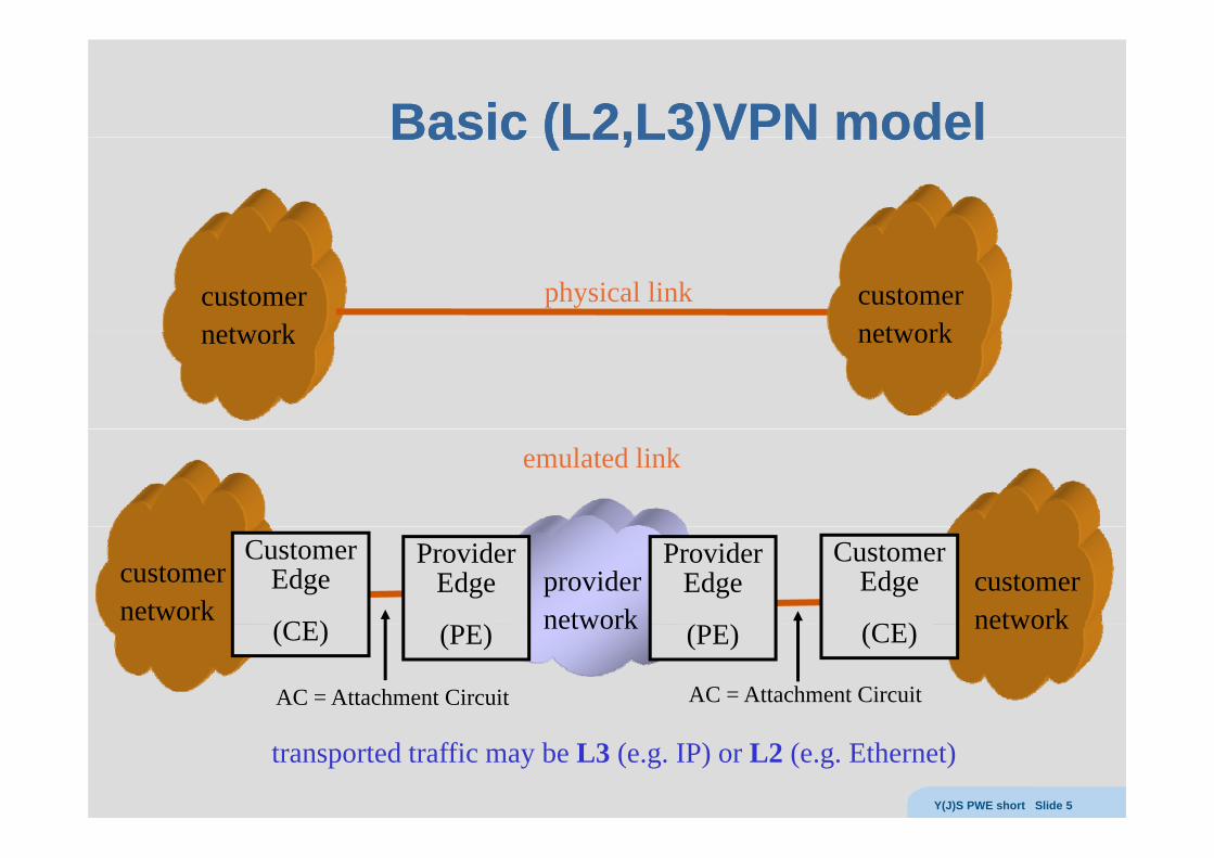
Basic (LBasic (L22,L,L33)VPN model)VPN modelBasic (LBasic (L22,L,L33)VPN model)VPN model
customernetwork
customernetwork
physical linknetwork network
emulated link
ProviderEdge
CustomerEdge
(CE)
providernetwork
customernetwork
ProviderEdge
CustomerEdge
(CE)
customernetwork(PE)(CE) network (PE) (CE) network
AC = Attachment Circuit AC = Attachment Circuit
transported traffic may be L3 (e.g. IP) or L2 (e.g. Ethernet)Y(J)S PWE short Slide 5
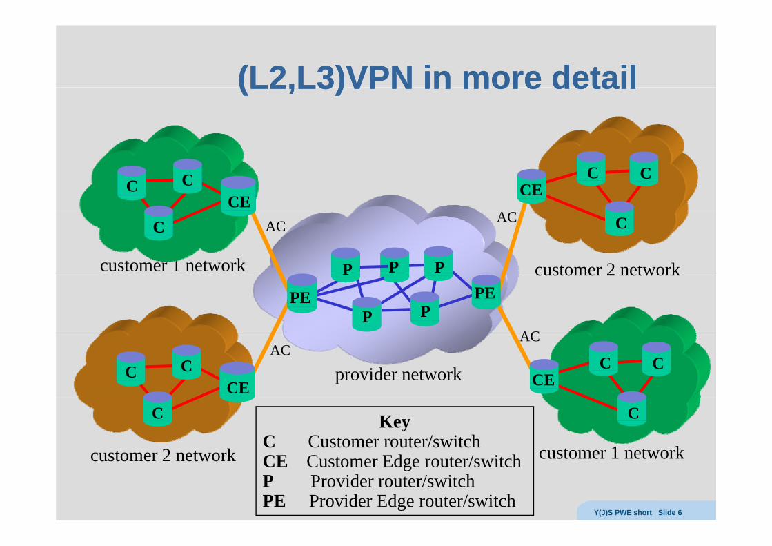
(L(L22,L,L33)VPN in more detail)VPN in more detail(L(L22,L,L33)VPN in more detail)VPN in more detail
C C CCCE
CE
customer 2 networkcustomer 1 network
C C
PPP
AC AC
customer 2 network
PPEPE
P
PAC
CCCEprovider networkC
CEC
ACAC
C
customer 2 network customer 1 network
KeyC Customer router/switchCE Customer Edge router/switch
C
customer 2 network CE Customer Edge router/switchP Provider router/switchPE Provider Edge router/switch
Y(J)S PWE short Slide 6
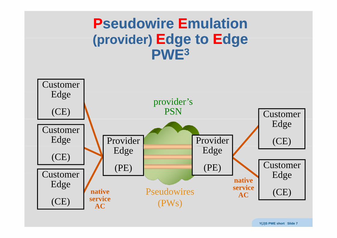
PPseudowire seudowire EEmulationmulation(provider)(provider) EEdgedge toto EEdgedge(provider) (provider) EEdge dge to to EEdgedge
PWEPWE33
CustomerEdEdge
(CE)provider’s
PSN Customer
ProviderCustomer
Edge
Edge
(CE)ProviderEdge
(PE)C stomer
(CE)
( )
CustomerEd
Edge
(PE)Customer
Edge
(CE)nativeservice
Pseudowires (PW )
Edge
(CE)nativeservice
AC(CE) service
AC (PWs)
Y(J)S PWE short Slide 7
Native services defined in IETF PWENative services defined in IETF PWE33Native services defined in IETF PWENative services defined in IETF PWE33
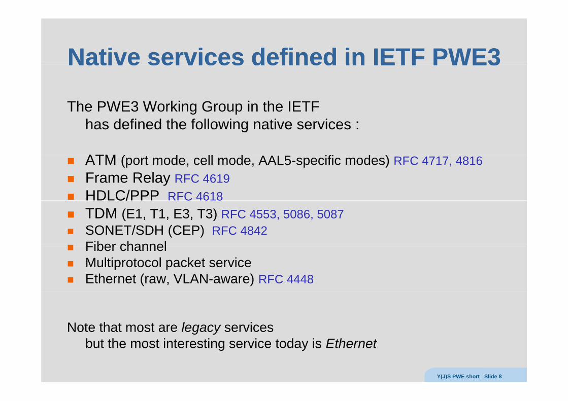
The PWE3 Working Group in the IETFThe PWE3 Working Group in the IETF has defined the following native services :
ATMATM (port mode, cell mode, AAL5-specific modes) RFC 4717, 4816Frame Relay RFC 4619HDLC/PPP RFC 4618C/ C 6 8TDM (E1, T1, E3, T3) RFC 4553, 5086, 5087SONET/SDH (CEP) RFC 4842Fiber channelFiber channel Multiprotocol packet serviceEthernet (raw, VLAN-aware) RFC 4448
Note that most are legacy servicesbut the most interesting service today is Ethernet
Y(J)S PWE short Slide 8
What else ?What else ?What else ?What else ?
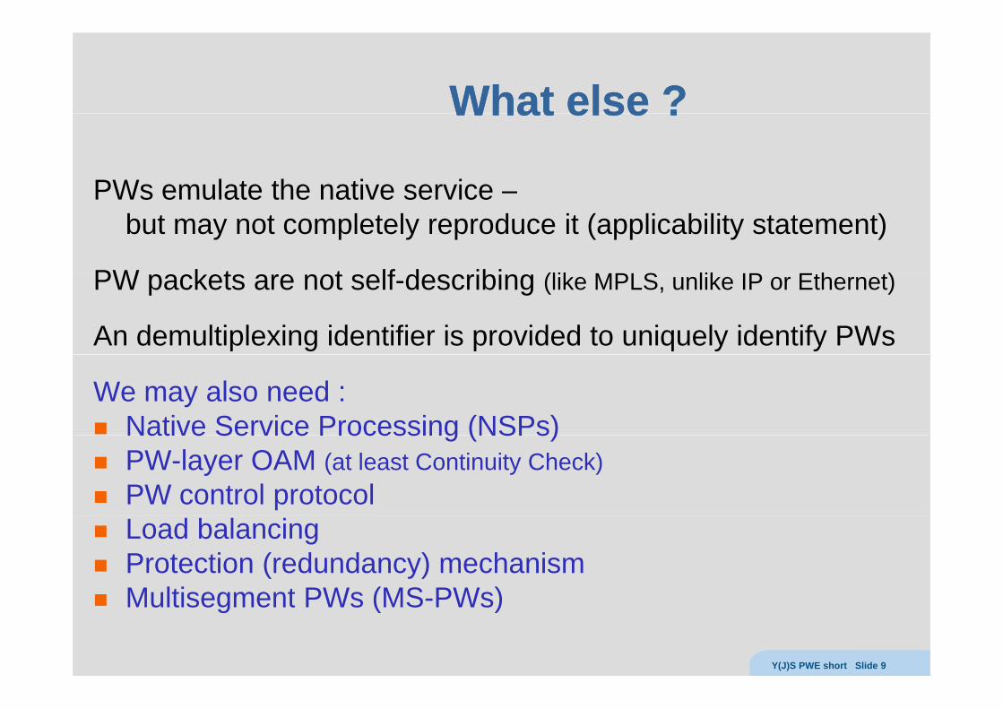
PWs emulate the native service –PWs emulate the native service but may not completely reproduce it (applicability statement)
PW k t t lf d ibi (lik MPLS lik IP Eth t)PW packets are not self-describing (like MPLS, unlike IP or Ethernet)
An demultiplexing identifier is provided to uniquely identify PWs
We may also need :Native Service Processing (NSPs)Native Service Processing (NSPs)PW-layer OAM (at least Continuity Check)PW control protocolLoad balancingProtection (redundancy) mechanism Multisegment PWs (MS PWs)Multisegment PWs (MS-PWs)
Y(J)S PWE short Slide 9
SimplisticSimplistic MPLS solutionMPLS solutionSimplistic Simplistic MPLS solutionMPLS solutionCE
CE
P PEPE PCE
CECE
CE
CEACs ACs
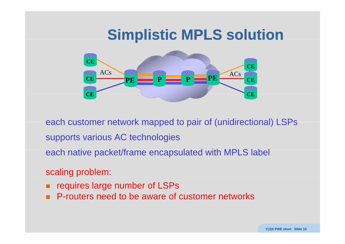
each customer network mapped to pair of (unidirectional) LSPs
CECE
each customer network mapped to pair of (unidirectional) LSPs
supports various AC technologies
h ti k t/f l t d ith MPLS l b leach native packet/frame encapsulated with MPLS label
scaling problem:requires large number of LSPsP-routers need to be aware of customer networks
Y(J)S PWE short Slide 10
(Martini) Pseudowires(Martini) Pseudowires(Martini) Pseudowires(Martini) Pseudowires
CE
transport tunnelPE
CE
CE PE CE
CEACs ACs
CE CE
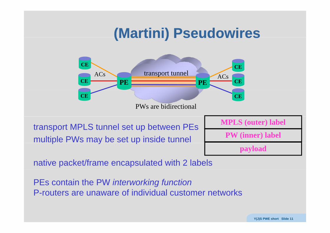
PWs are bidirectional
transport MPLS tunnel set up between PEsmultiple PWs may be set up inside tunnel PW (inner) label
MPLS (outer) label
p y p
native packet/frame encapsulated with 2 labels
payload
PEs contain the PW interworking functionP-routers are unaware of individual customer networks
Y(J)S PWE short Slide 11
PseudowirePseudowireencapsulationsencapsulationsencapsulationsencapsulations
Encapsulation:Encapsulation: IIn order to enable transport over the PSNn order to enable transport over the PSNEncapsulation: Encapsulation: IIn order to enable transport over the PSN, n order to enable transport over the PSN, native service Protocol Data Units (PDUs) must be inserted native service Protocol Data Units (PDUs) must be inserted into packets of the appropriate format.into packets of the appropriate format.This is usually accomplished by adding headersThis is usually accomplished by adding headersThis is usually accomplished by adding headers.This is usually accomplished by adding headers.
Y(J)S PWE short Slide 12
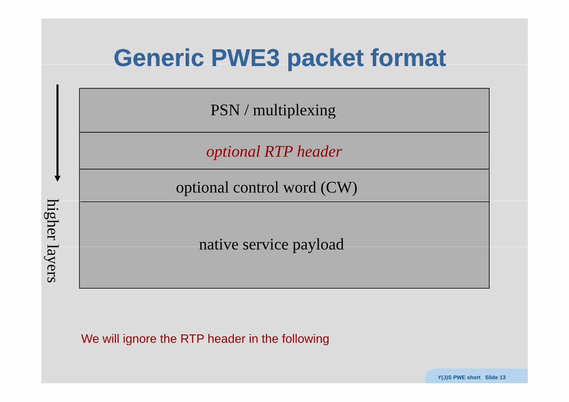
Generic PWEGeneric PWE33 packet formatpacket formatGeneric PWEGeneric PWE3 3 packet formatpacket format
PSN / multiplexingPSN / multiplexing
optional RTP headeroptional RTP header
optional control word (CW) hhigher l native service payloadlayers
native service payload
We will ignore the RTP header in the followingWe will ignore the RTP header in the following
Y(J)S PWE short Slide 13
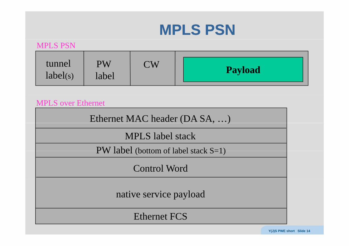
MPLS PSNMPLS PSN
tunnel PW CW P l d
MPLS PSN
label(s)PW label
CW Payload
MPLS over Ethernet
Ethernet MAC header (DA SA, …)( , )
MPLS label stackPW label (bottom of label stack S=1)
Control Word
PW label (bottom of label stack S=1)
native service payload
Ethernet FCSY(J)S PWE short Slide 14
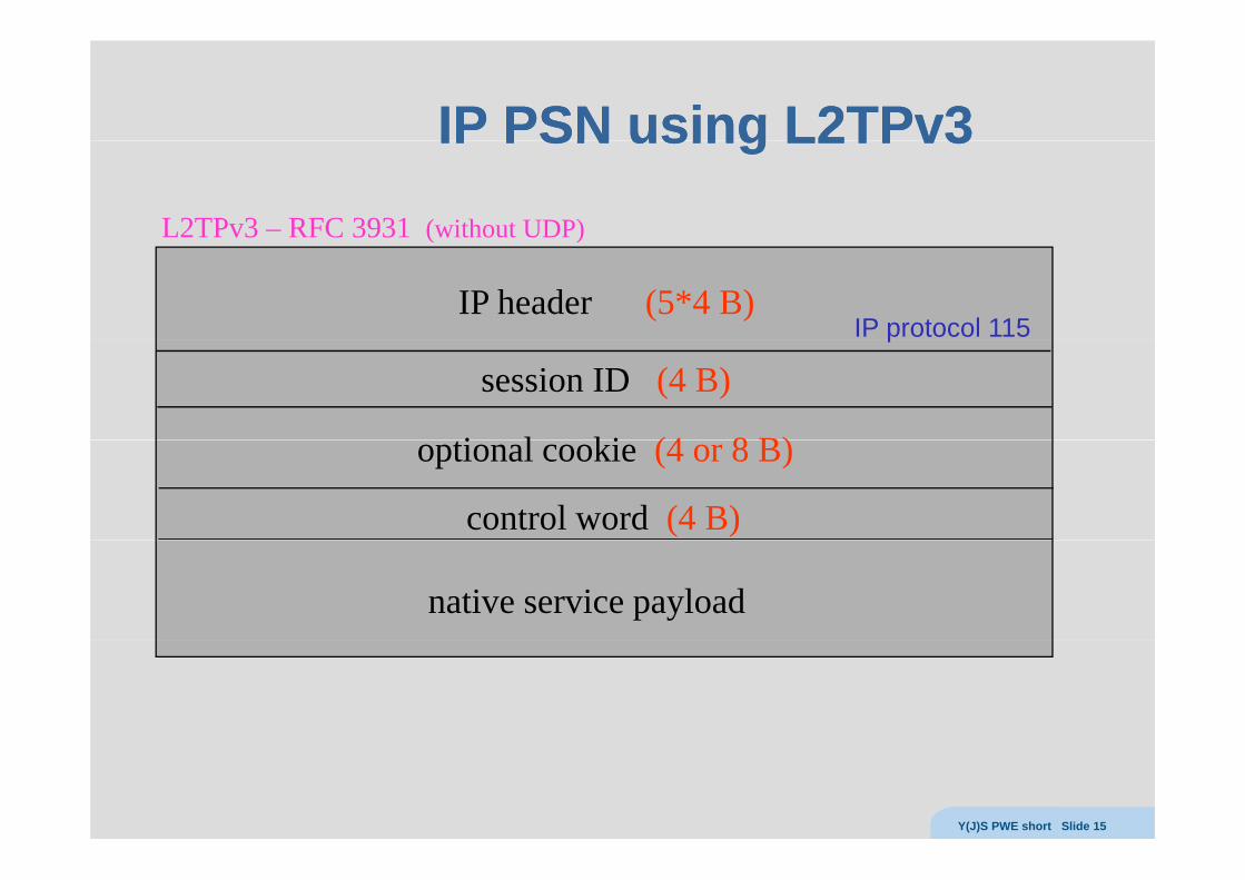
IP PSN using LIP PSN using L22TPvTPv33IP PSN using LIP PSN using L22TPvTPv33
L2TPv3 – RFC 3931 (without UDP)
IP header (5*4 B)
( )
IP protocol 115
session ID (4 B)
i l ki (4 8 B)
p
optional cookie (4 or 8 B)
control word (4 B)
native service payload
Y(J)S PWE short Slide 15
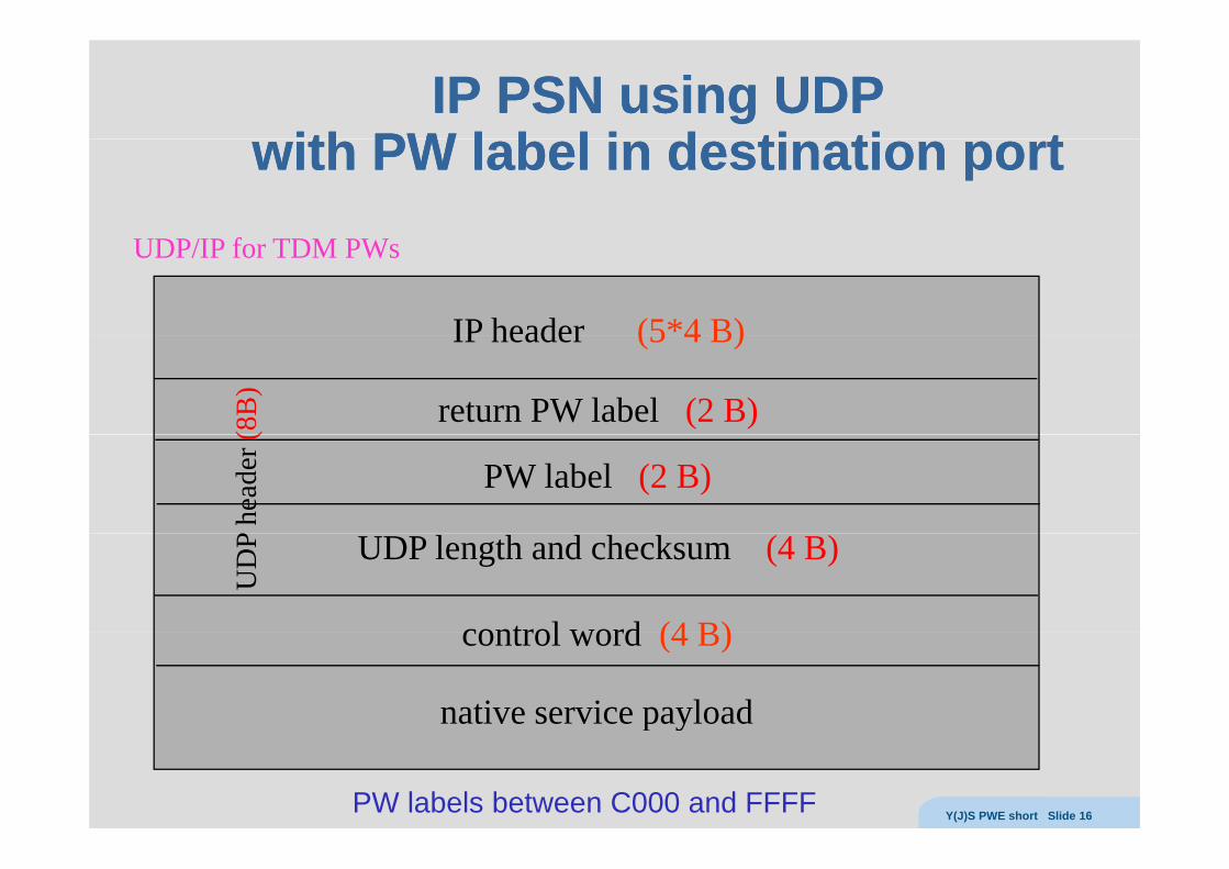
IP PSN using UDPIP PSN using UDPith PW l b l i d ti ti tith PW l b l i d ti ti twith PW label in destination portwith PW label in destination port
UDP/IP for TDM PWs
IP header (5*4 B)IP header (5 4 B)
return PW label (2 B)(8B
)
PW label (2 B)
P he
ader
(
control word (4 B)
UDP length and checksum (4 B)
UD
P
control word (4 B)
native service payloadp y
PW labels between C000 and FFFF Y(J)S PWE short Slide 16
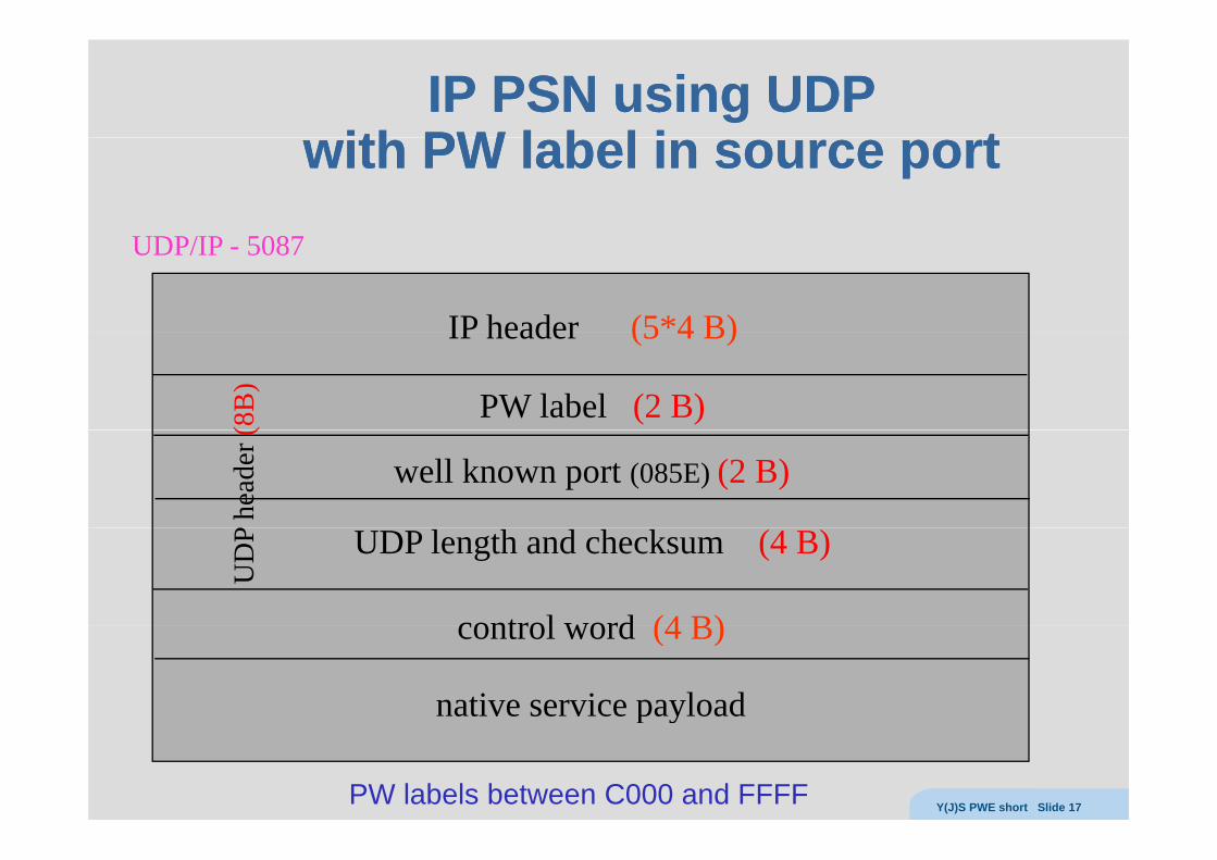
IP PSN using UDPIP PSN using UDPith PW l b l i tith PW l b l i twith PW label in source portwith PW label in source port
UDP/IP - 5087
IP header (5*4 B)IP header (5 4 B)
PW label (2 B)(8B
)
well known port (085E) (2 B)
P he
ader
(
control word (4 B)
UDP length and checksum (4 B)
UD
P
control word (4 B)
native service payloadp y
PW labels between C000 and FFFF Y(J)S PWE short Slide 17
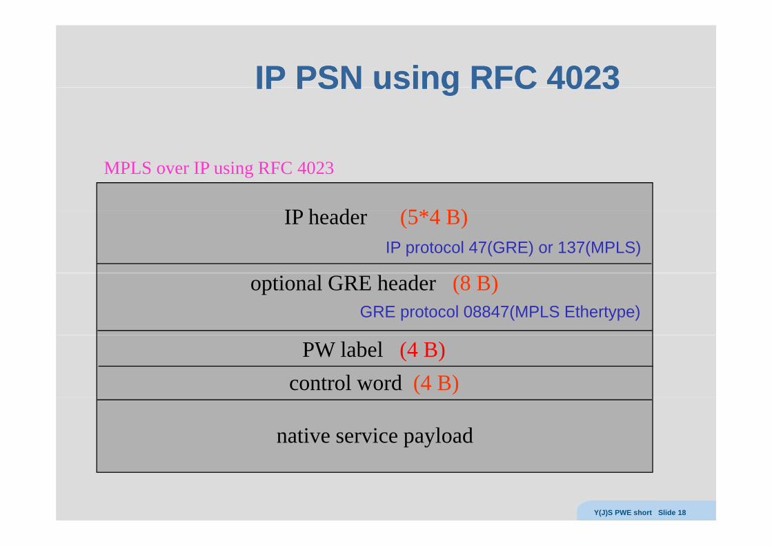
IP PSN using RFCIP PSN using RFC 40234023IP PSN using RFC IP PSN using RFC 40234023
MPLS over IP using RFC 4023
IP h d (5*4 B)IP header (5*4 B) IP protocol 47(GRE) or 137(MPLS)
optional GRE header (8 B) GRE protocol 08847(MPLS Ethertype)
PW label (4 B)control word (4 B)
native service payload
Y(J)S PWE short Slide 18
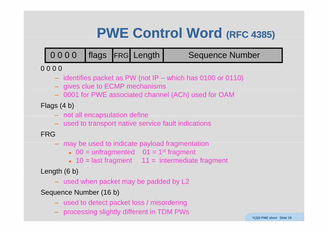
PWE ControlPWE Control WordWord (RFC(RFC 43854385))PWE Control PWE Control Word Word (RFC (RFC 43854385))
0 0 0 0 flags FRG Length Sequence Number0 0 0 0
– identifies packet as PW (not IP – which has 0100 or 0110)– gives clue to ECMP mechanismsg– 0001 for PWE associated channel (ACh) used for OAM
Flags (4 b)– not all encapsulation definenot all encapsulation define– used to transport native service fault indications
FRGmay be used to indicate payload fragmentation– may be used to indicate payload fragmentation
00 = unfragmented 01 = 1st fragment 10 = last fragment 11 = intermediate fragment
L th (6 b)Length (6 b) – used when packet may be padded by L2
Sequence Number (16 b) q ( )– used to detect packet loss / misordering– processing slightly different in TDM PWs
Y(J)S PWE short Slide 19

TDM PWsTDM PWs
Y(J)S PWE short Slide 20

TDM PWTDM PW Protocol ProcessingProtocol ProcessingTDM PW TDM PW Protocol ProcessingProtocol ProcessingTDM TDMPSN Packets PSN Packets TDM
PSN
Steps in TDM PW processingThe synchronous bit stream is segmentedThe synchronous bit stream is segmentedThe TDM segments may be adaptedTDMoIP control word is prependedTDMoIP control word is prependedPSN headers are prepended (encapsulation)Packets are transported over PSN to destinationPackets are transported over PSN to destinationPSN headers are utilized and strippedControl word is checked, utilized and strippedppTDM stream is reconstituted (using adaptation) and played out
Y(J)S PWE short Slide 21
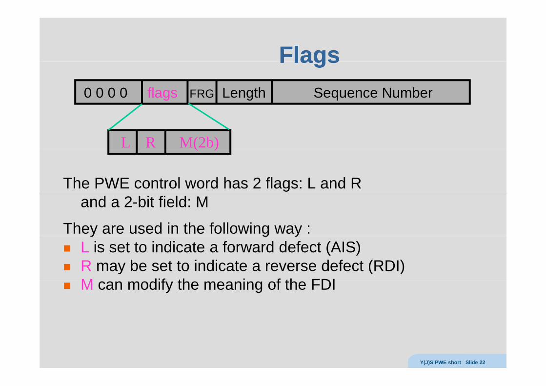
FlagsFlagsFlagsFlags0 0 0 0 flags FRG Length Sequence Number
L R M(2b)
The PWE control word has 2 flags: L and R
( )
and a 2-bit field: M
They are used in the following way :y g yL is set to indicate a forward defect (AIS)R may be set to indicate a reverse defect (RDI)M dif th i f th FDIM can modify the meaning of the FDI
Y(J)S PWE short Slide 22
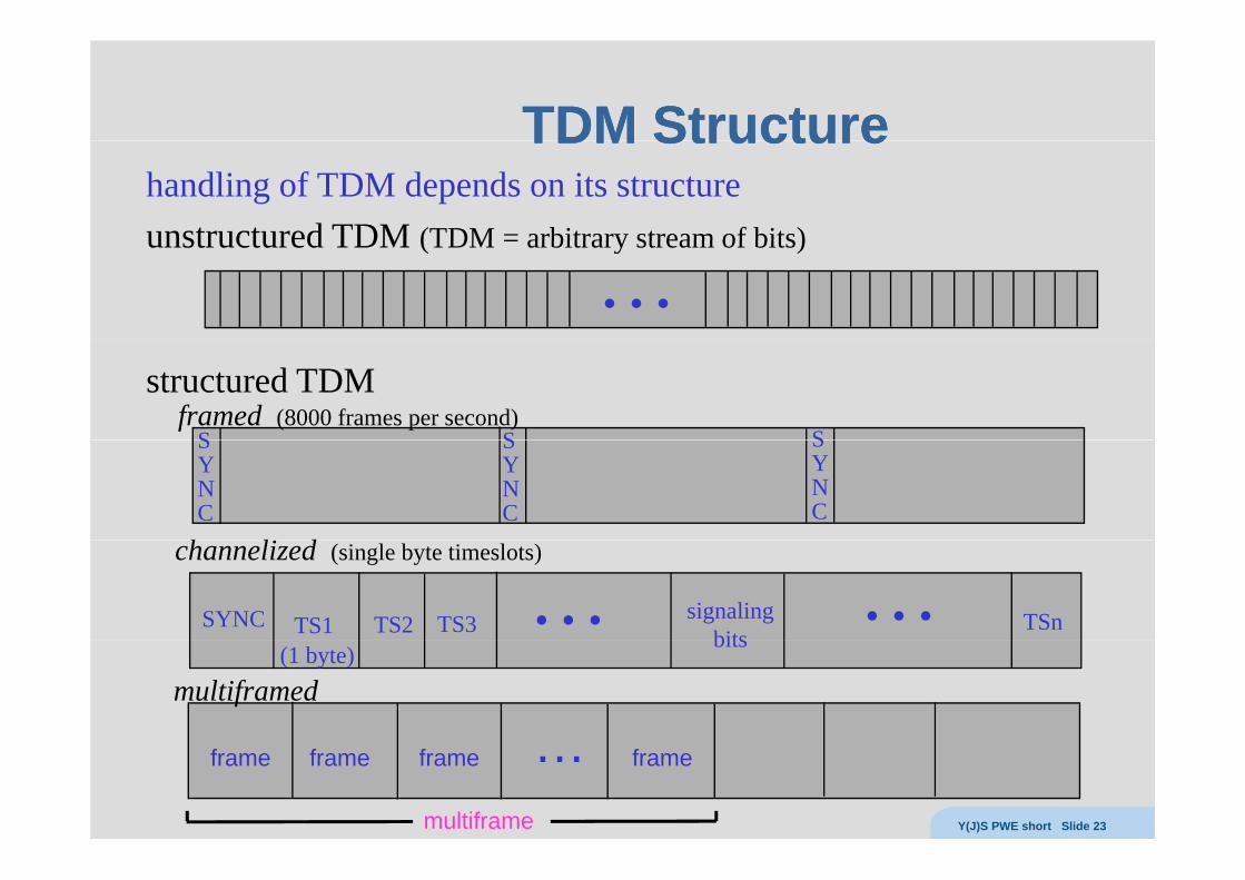
TDM StructureTDM StructureTDM StructureTDM Structurehandling of TDM depends on its structureunstructured TDM (TDM = arbitrary stream of bits)unstructured TDM (TDM = arbitrary stream of bits)
…structured TDM
Sframed (8000 frames per second)
S S
h l d
SYNC
SYNC
SYNC
SYNC TS1 TS2 TS3 signalingbits
… … TSn
channelized (single byte timeslots)
bits(1 byte)
multiframed
frame frame frame … frame
multiframe Y(J)S PWE short Slide 23
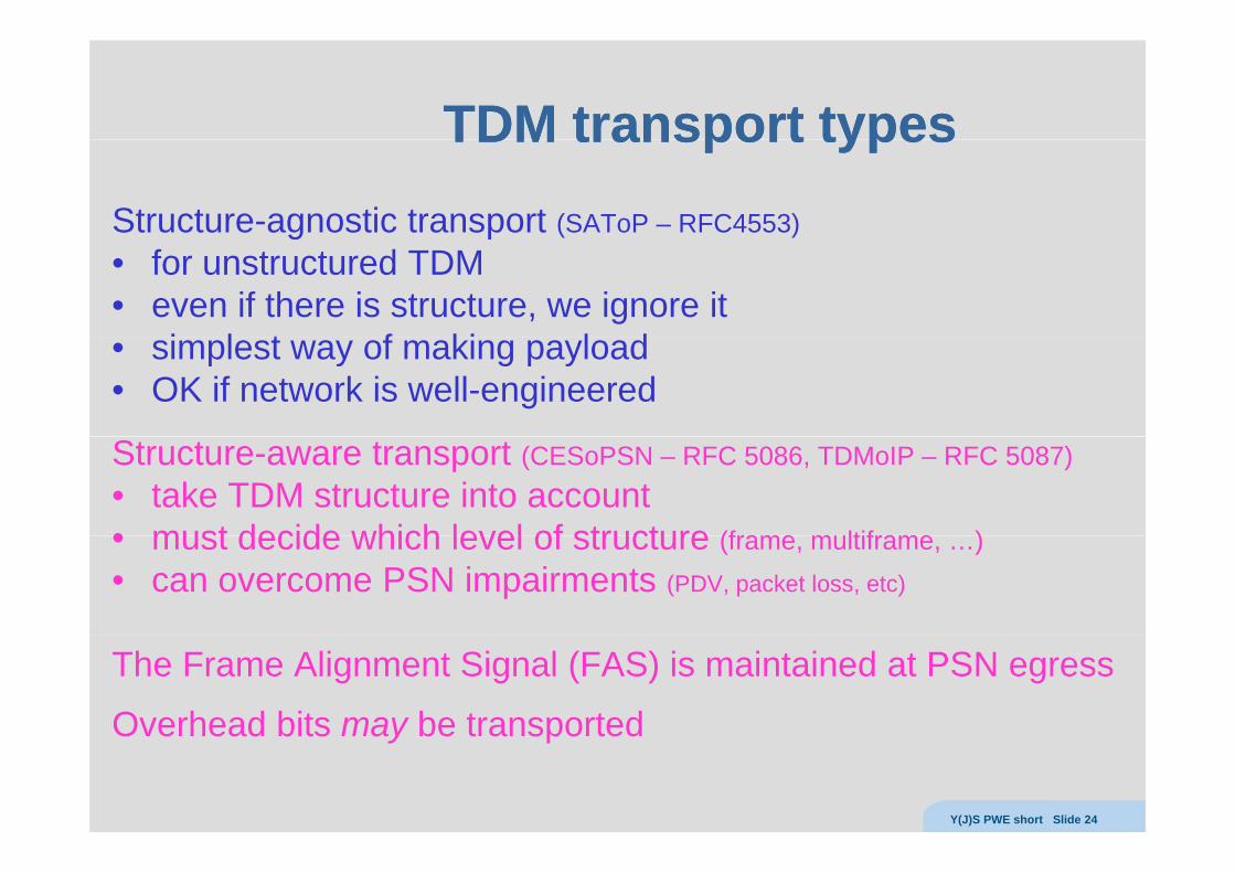
TDM transport typesTDM transport typesTDM transport typesTDM transport typesStructure-agnostic transport (SAToP – RFC4553)g p• for unstructured TDM• even if there is structure, we ignore it
i l t f ki l d• simplest way of making payload• OK if network is well-engineered
Structure-aware transport (CESoPSN – RFC 5086, TDMoIP – RFC 5087)• take TDM structure into account• must decide which level of structure (frame multiframe )• must decide which level of structure (frame, multiframe, …)• can overcome PSN impairments (PDV, packet loss, etc)
The Frame Alignment Signal (FAS) is maintained at PSN egress
Overhead bits may be transportedOverhead bits may be transported
Y(J)S PWE short Slide 24

Structure Agnostic TransportStructure Agnostic TransportStructure Agnostic TransportStructure Agnostic Transport
SAToP encapsulates N bytes of TDM in each packetThere is no TDM frame alignment !There is no TDM frame alignment !
N must be constant and preconfiguredIf packets are lost, the egress knows how many TDM bytes to fill in
Default values for N :E1 – 256 BT1 192 BT1 – 192 BE3 and T3 – 1024 B
For T1 there is an optional special mode called octet aligned modeFor T1 there is an optional special mode called octet aligned modethat adds 7 bits of padding to every 193 consecutive bits (to make 25 B)
Y(J)S PWE short Slide 25
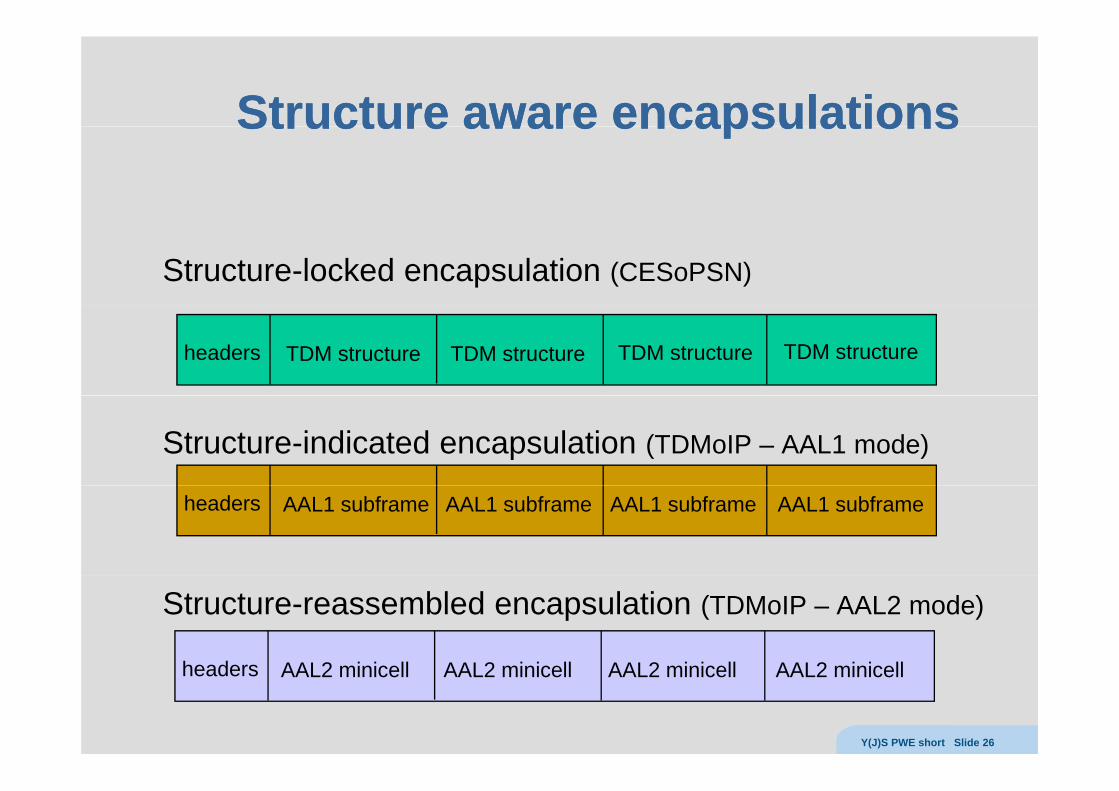
Structure aware encapsulationsStructure aware encapsulationsStructure aware encapsulationsStructure aware encapsulations
Structure-locked encapsulation (CESoPSN)
headers TDM structure TDM structure TDM structureTDM structure
Structure-indicated encapsulation (TDMoIP – AAL1 mode)
headers AAL1 subframe AAL1 subframe AAL1 subframe AAL1 subframe
Structure-reassembled encapsulation (TDMoIP – AAL2 mode)
headers AAL2 i i ll AAL2 i i ll AAL2 i i ll AAL2 i i llheaders AAL2 minicell AAL2 minicell AAL2 minicell AAL2 minicell
Y(J)S PWE short Slide 26
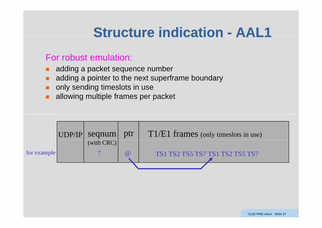
Structure indicationStructure indication -- AALAAL11Structure indication Structure indication AALAAL11For robust emulation:
adding a packet sequence numberadding a pointer to the next superframe boundaryonly sending timeslots in useonly sending timeslots in useallowing multiple frames per packet
UDP/IP T1/E1 frames (only timeslots in use)seqnum ptr
for example(with CRC)
TS1 TS2 TS5 TS7 TS1 TS2 TS5 TS77 @
Y(J)S PWE short Slide 27

Structure reassemblyStructure reassembly -- AALAAL22Structure reassembly Structure reassembly AALAAL22
TDM frame TDM frame TDM frameTDM frameTDM frame
1 2 4 531 1 2 2 3 3 4 4 5 5
1 2 3 4 5hdr 1 2 3 4 5hdr 1 2 3 4 5hdrPSN hdrs CW
TS1 TS2 TS3
AAL1 is inefficient when timeslots are dynamically allocatedeach minicell consists of a header and buffered dataminicell header contains:– CID (Channel IDentifier)– LI (Length Indicator) = length-1
UUI (User User Indication) counter + payload type ID– UUI (User-User Indication) counter + payload type ID
Y(J)S PWE short Slide 28
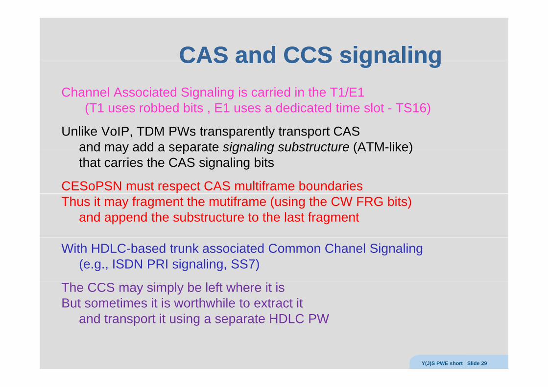
CAS and CCS signalingCAS and CCS signalingCAS and CCS signalingCAS and CCS signalingChannel Associated Signaling is carried in the T1/E1
(T1 uses robbed bits E1 uses a dedicated time slot TS16)(T1 uses robbed bits , E1 uses a dedicated time slot - TS16)
Unlike VoIP, TDM PWs transparently transport CASand may add a separate signaling substructure (ATM-like)and may add a separate signaling substructure (ATM like)that carries the CAS signaling bits
CESoPSN must respect CAS multiframe boundaries Thus it may fragment the mutiframe (using the CW FRG bits)
and append the substructure to the last fragment
With HDLC-based trunk associated Common Chanel Signaling (e.g., ISDN PRI signaling, SS7)
The CCS may simply be left where it isBut sometimes it is worthwhile to extract it
and transport it using a separate HDLC PWp g p
Y(J)S PWE short Slide 29
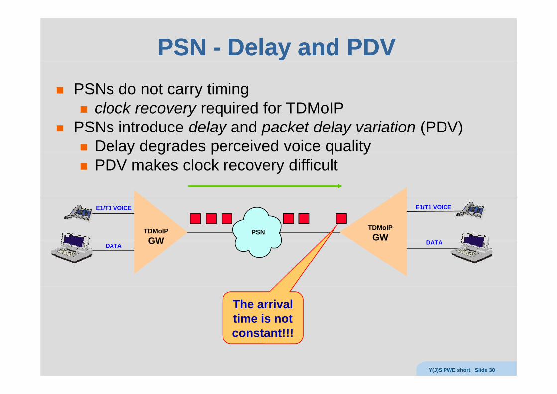
PSN PSN -- Delay and PDVDelay and PDVPSNs do not carry timing
clock recovery required for TDMoIPclock recovery required for TDMoIPPSNs introduce delay and packet delay variation (PDV)
Delay degrades perceived voice qualityy g p q yPDV makes clock recovery difficult
PSN
E1/T1 VOICE E1/T1 VOICE
DATA
TDMoIPGW
TDMoIPGW
DATA DATAGW
The arrival time is not constant!!!constant!!!
Y(J)S PWE short Slide 30
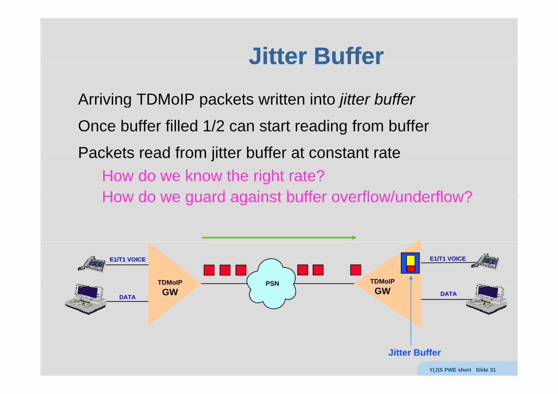
Jitter BufferJitter BufferJitter BufferJitter BufferArriving TDMoIP packets written into jitter bufferg p j
Once buffer filled 1/2 can start reading from buffer
Packets read from jitter buffer at constant ratePackets read from jitter buffer at constant rateHow do we know the right rate?How do we guard against buffer overflow/underflow?How do we guard against buffer overflow/underflow?
PSN
E1/T1 VOICE E1/T1 VOICE
TDMoIP TDMoIP
DATA DATAGW GW
Jitter Buffer Y(J)S PWE short Slide 31
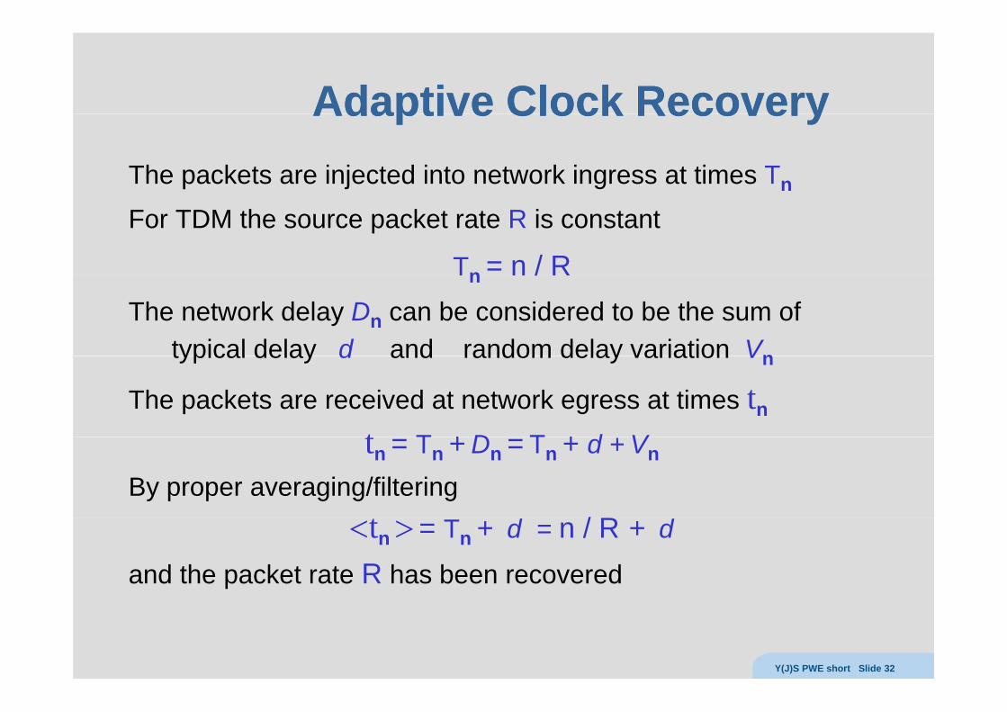
Adaptive ClockAdaptive Clock RecoveryRecoveryAdaptive Clock Adaptive Clock RecoveryRecoveryThe packets are injected into network ingress at times Tn
For TDM the source packet rate R is constant
Tn = n / RTn n / RThe network delay Dn can be considered to be the sum of
typical delay d and random delay variation Vntypical delay d and random delay variation Vn
The packets are received at network egress at times tn
t T + D T + d Vtn = Tn + Dn = Tn + d + Vn
By proper averaging/filtering / R<tn > = Tn + d = n / R + d
and the packet rate R has been recovered
Y(J)S PWE short Slide 32
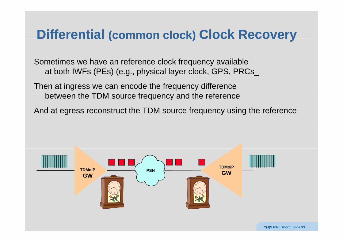
DifferentialDifferential (common clock)(common clock) Clock RecoveryClock RecoveryDifferential Differential (common clock) (common clock) Clock Recovery Clock Recovery
Sometimes we have an reference clock frequency available yat both IWFs (PEs) (e.g., physical layer clock, GPS, PRCs_
Then at ingress we can encode the frequency difference b t th TDM f d th fbetween the TDM source frequency and the reference
And at egress reconstruct the TDM source frequency using the reference
PSNTDMoIPGW
TDMoIPGWGW
Y(J)S PWE short Slide 33
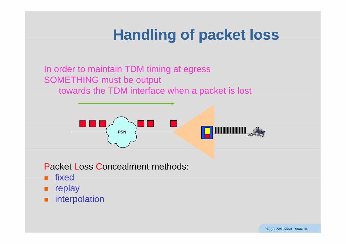
Handling of packet lossHandling of packet lossHandling of packet lossHandling of packet loss
I d t i t i TDM ti i tIn order to maintain TDM timing at egress SOMETHING must be output
towards the TDM interface when a packet is lostp
PSN
Packet Loss Concealment methods:fixedfixedreplayinterpolation
Y(J)S PWE short Slide 34
MisMis--orderingorderingMisMis orderingordering
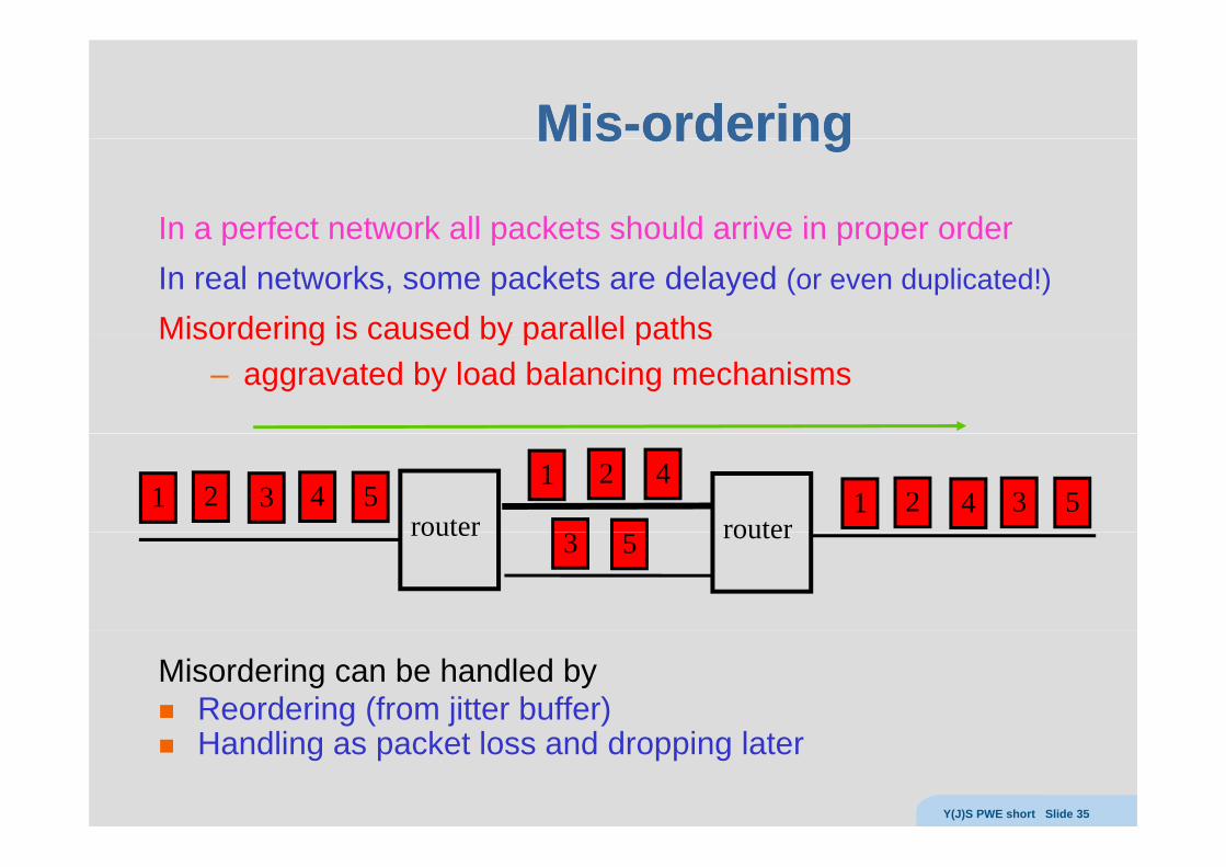
In a perfect network all packets should arrive in proper orderIn a perfect network all packets should arrive in proper orderIn real networks, some packets are delayed (or even duplicated!)
Misordering is caused by parallel pathsMisordering is caused by parallel paths– aggravated by load balancing mechanisms
router router1 2 3 4 5 1 2 4 3 5
1 2 4
router router3 5
Misordering can be handled byReordering (from jitter buffer)Handling as packet loss and dropping later
Y(J)S PWE short Slide 35
Ethernet PWsEthernet PWsEthernet PWsEthernet PWs
Y(J)S PWE short Slide 36
Ethernet limitationsEthernet limitationsEthernet limitationsEthernet limitations
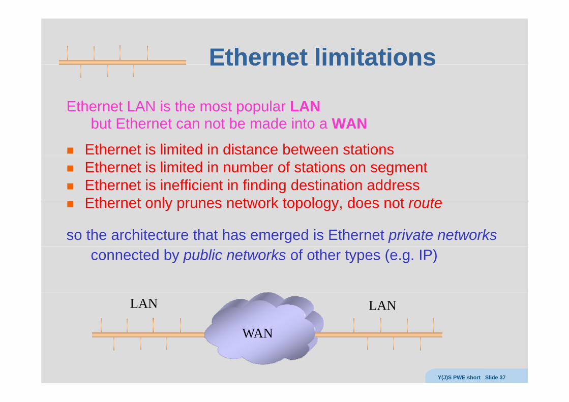
Ethernet LAN is the most popular LANEthernet LAN is the most popular LANbut Ethernet can not be made into a WAN
Ethernet is limited in distance between stationsEthernet is limited in number of stations on segmentEthernet is inefficient in finding destination addressEthernet only prunes network topology does not routeEthernet only prunes network topology, does not route
so the architecture that has emerged is Ethernet private networksconnected by public networks of other types (e.g. IP)
WAN
LAN LAN
Y(J)S PWE short Slide 37
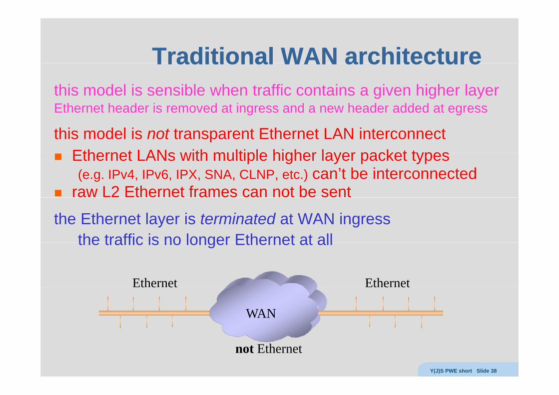
Traditional WAN architectureTraditional WAN architectureTraditional WAN architectureTraditional WAN architecturethis model is sensible when traffic contains a given higher layerEthernet header is removed at ingress and a new header added at egressEthernet header is removed at ingress and a new header added at egress
this model is not transparent Ethernet LAN interconnectEthernet LANs with multiple higher layer packet typesEthernet LANs with multiple higher layer packet types (e.g. IPv4, IPv6, IPX, SNA, CLNP, etc.) can’t be interconnected
raw L2 Ethernet frames can not be sent
the Ethernet layer is terminated at WAN ingressthe traffic is no longer Ethernet at allthe traffic is no longer Ethernet at all
Ethernet Ethernett e et t e et
WAN
not EthernetY(J)S PWE short Slide 38
Tunneling Ethernet framesTunneling Ethernet framesTunneling Ethernet framesTunneling Ethernet frames
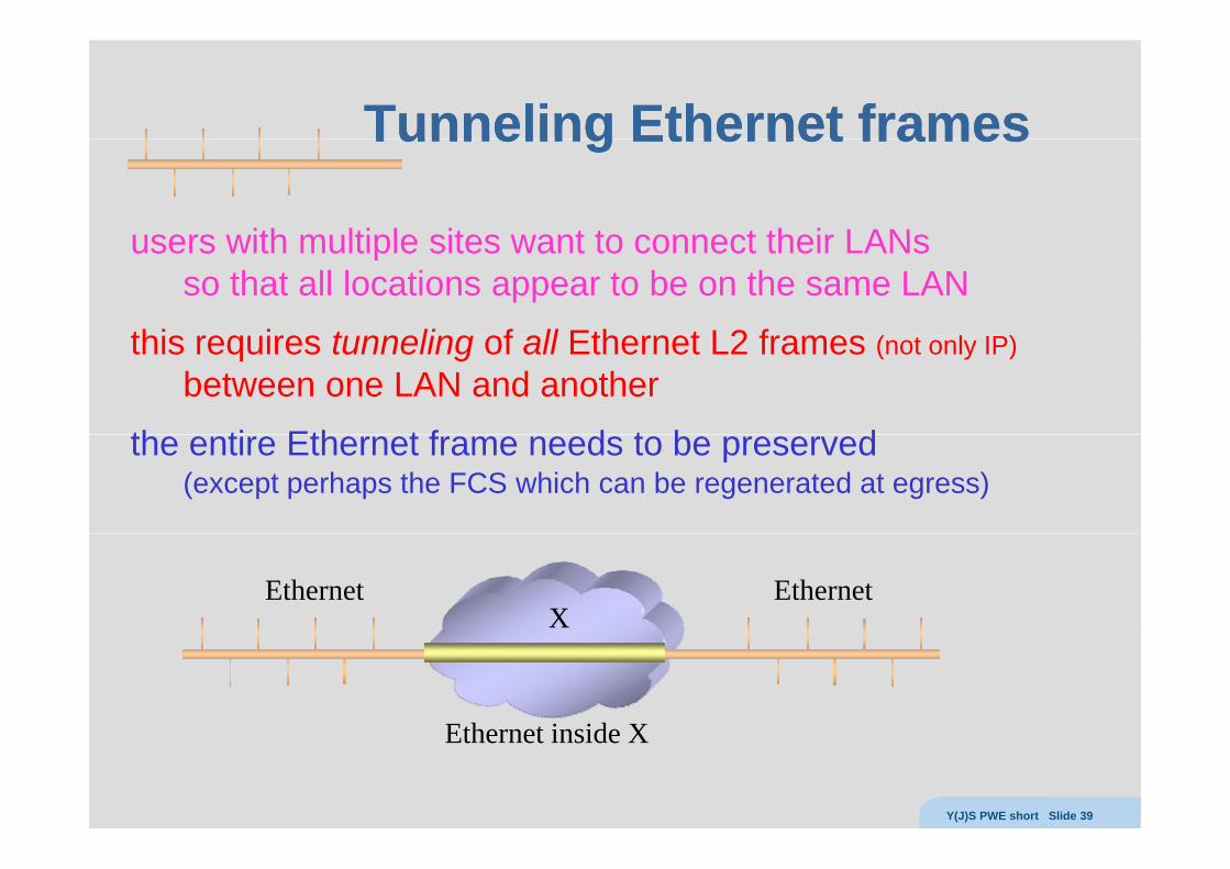
users with multiple sites want to connect their LANsusers with multiple sites want to connect their LANsso that all locations appear to be on the same LAN
this req ires t nneling of all Ethernet L2 frames ( t l IP)this requires tunneling of all Ethernet L2 frames (not only IP)between one LAN and another
th ti Eth t f d t b dthe entire Ethernet frame needs to be preserved(except perhaps the FCS which can be regenerated at egress)
Ethernet EthernetX
Ethernet inside XEthernet inside X
Y(J)S PWE short Slide 39
EthernetEthernet over Xover XEthernet Ethernet over Xover X
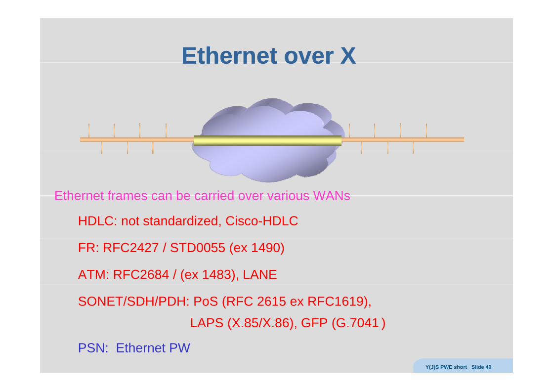
Ethernet frames can be carried over various WANsEthernet frames can be carried over various WANs
HDLC: not standardized, Cisco-HDLC
FR: RFC2427 / STD0055 (ex 1490)
ATM: RFC2684 / (ex 1483), LANE
SONET/SDH/PDH: PoS (RFC 2615 ex RFC1619),LAPS (X.85/X.86), GFP (G.7041 )( ), ( )
PSN: Ethernet PWY(J)S PWE short Slide 40
Ethernet PW (RFCEthernet PW (RFC 44484448))Ethernet PW (RFC Ethernet PW (RFC 44484448))
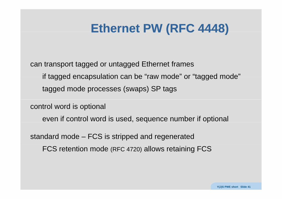
can transport tagged or untagged Ethernet frames
if tagged encapsulation can be “raw mode” or “tagged mode”if tagged encapsulation can be raw mode or tagged mode
tagged mode processes (swaps) SP tags
control word is optional
even if control word is used, sequence number if optional, q p
standard mode – FCS is stripped and regenerated
FCS retention mode (RFC 4720) allows retaining FCS
Y(J)S PWE short Slide 41
Ethernet Pseudowire packet (MPLS)Ethernet Pseudowire packet (MPLS)Ethernet Pseudowire packet (MPLS)Ethernet Pseudowire packet (MPLS)
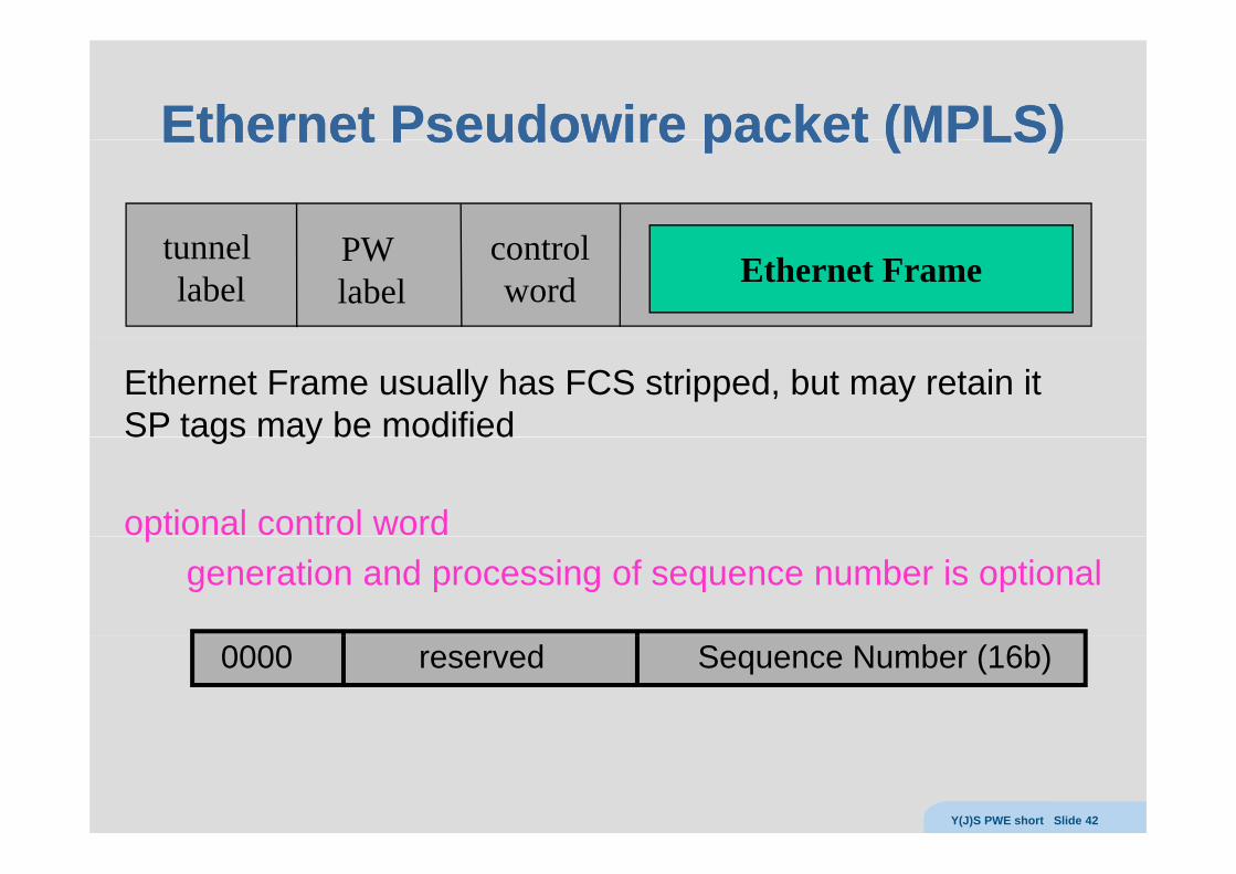
t l PW t ltunnel label
PW label
controlword Ethernet Frame
Ethernet Frame usually has FCS stripped, but may retain itSP tags may be modifiedS ags ay be od ed
optional control word pgeneration and processing of sequence number is optional
0000 reserved Sequence Number (16b)
Y(J)S PWE short Slide 42
LL22VPNsVPNs
Y(J)S PWE short Slide 43
VPWSVPWSVPWSVPWS
CE CEAC ACPE PE
providernetwork
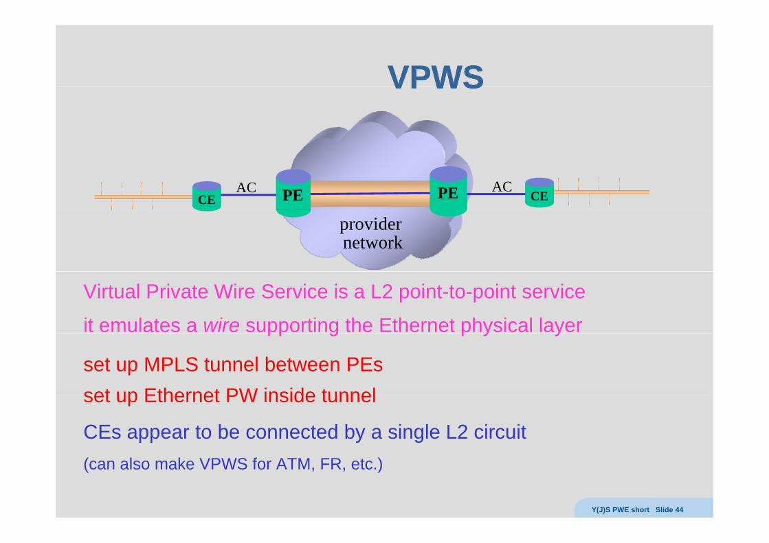
Virtual Private Wire Service is a L2 point-to-point service
it emulates a wire supporting the Ethernet physical layerpp g p y y
set up MPLS tunnel between PEsset up Ethernet PW inside tunnelset up Ethernet PW inside tunnel
CEs appear to be connected by a single L2 circuit(can also make VPWS for ATM, FR, etc.)
Y(J)S PWE short Slide 44
VPLSVPLSVPLSVPLS
CEACPE
CE
CE
AC
PE
PE
CE
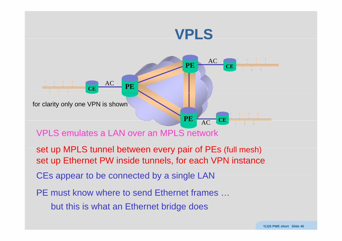
for clarity only one VPN is shown
ACPE
VPLS emulates a LAN over an MPLS network
set up MPLS tunnel between every pair of PEs (f ll h)
CEACPE
set up MPLS tunnel between every pair of PEs (full mesh)set up Ethernet PW inside tunnels, for each VPN instance
CEs appear to be connected by a single LANCEs appear to be connected by a single LAN
PE must know where to send Ethernet frames …but this is what an Ethernet bridge does
Y(J)S PWE short Slide 45
VPLSVPLSVPLSVPLS
CEV B
CE
CEV B
B V
V B CE
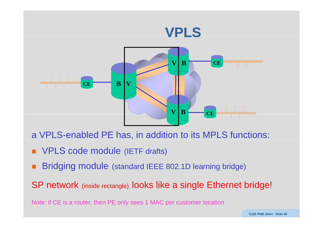
a VPLS-enabled PE has, in addition to its MPLS functions:
V B CE
VPLS code module (IETF drafts)
Bridging module (standard IEEE 802 1D learning bridge)Bridging module (standard IEEE 802.1D learning bridge)
SP network (inside rectangle) looks like a single Ethernet bridge!
Note: if CE is a router, then PE only sees 1 MAC per customer location
Y(J)S PWE short Slide 46
VPLS bridgeVPLS bridgeVPLS bridgeVPLS bridgePE maintains a separate bridging module for each VPN (VPLS instance)
VPLS b id i d l t fVPLS bridging module must perform:MAC learningMAC agingMAC agingflooding of unknown MAC framesreplication (for unknown/multicast/broadcast frames)
unlike true bridge, Spanning Tree Protocol is not usedlimited traffic engineering capabilitiesscalability limitationsslow convergence
forwarding loops are avoided by split horizonPE never forwards packet from MPLS network to another PE
t li it ti i th i f ll h f PWnot a limitation since there is a full mesh of PWsso always send directly to the right PE
Y(J)S PWE short Slide 47
BridgeBridge -- both waysboth waysBridge Bridge both waysboth ways
CEV B
CE
CE
CE
CEV B
B VCE
V B CE
CE
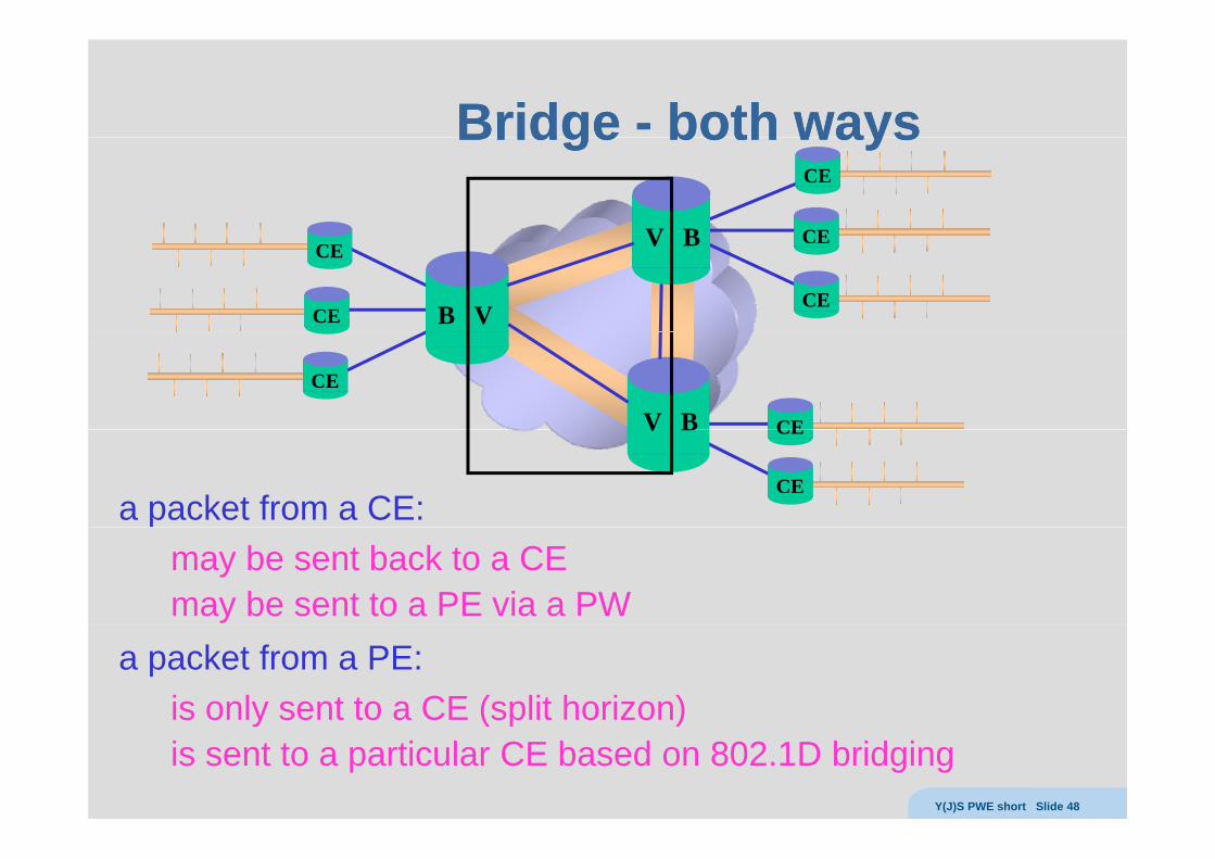
a packet from a CE:
V B CE
CE
may be sent back to a CEmay be sent to a PE via a PW
a packet from a PE:is only sent to a CE (split horizon)y ( p )is sent to a particular CE based on 802.1D bridging
Y(J)S PWE short Slide 48
LL22VPN vs. LVPN vs. L33VPNVPNLL22VPN vs. LVPN vs. L33VPNVPN
PE
CE
CE
PE
PE
?CEPE
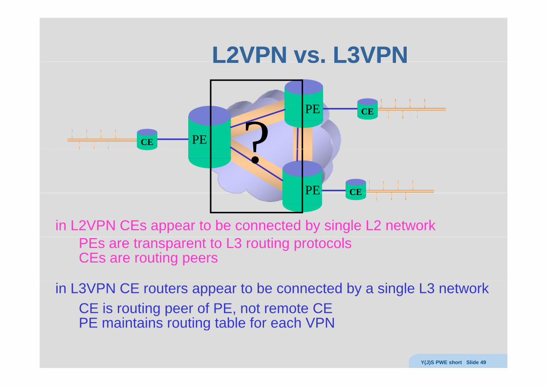
?in L2VPN CEs appear to be connected by single L2 network
CEPE
PEs are transparent to L3 routing protocolsCEs are routing peers
in L3VPN CE routers appear to be connected by a single L3 networkCE is routing peer of PE, not remote CE PE maintains routing table for each VPNPE maintains routing table for each VPN
Y(J)S PWE short Slide 49

PW PW OAMOAM
Y(J)S PWE short Slide 50
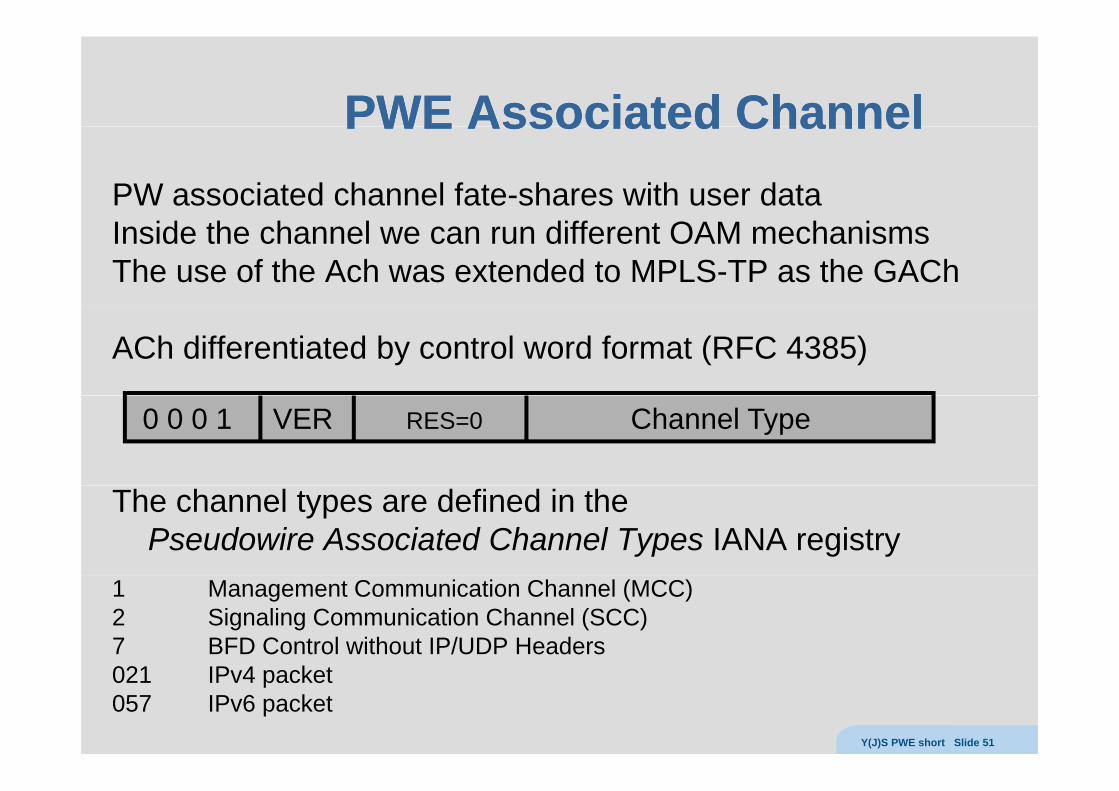
PWE Associated ChannelPWE Associated ChannelPWE Associated ChannelPWE Associated ChannelPW associated channel fate-shares with user dataInside the channel we can run different OAM mechanismsThe use of the Ach was extended to MPLS-TP as the GACh
ACh differentiated by control word format (RFC 4385)
0 0 0 1 VER RES=0 Channel Type
The channel types are defined in the Pseudowire Associated Channel Types IANA registry
1 Management Communication Channel (MCC) 2 Signaling Communication Channel (SCC) 7 BFD Control without IP/UDP Headers021 IPv4 packet 057 IPv6 packet
Y(J)S PWE short Slide 51
VCCVVCCVVCCVVCCV
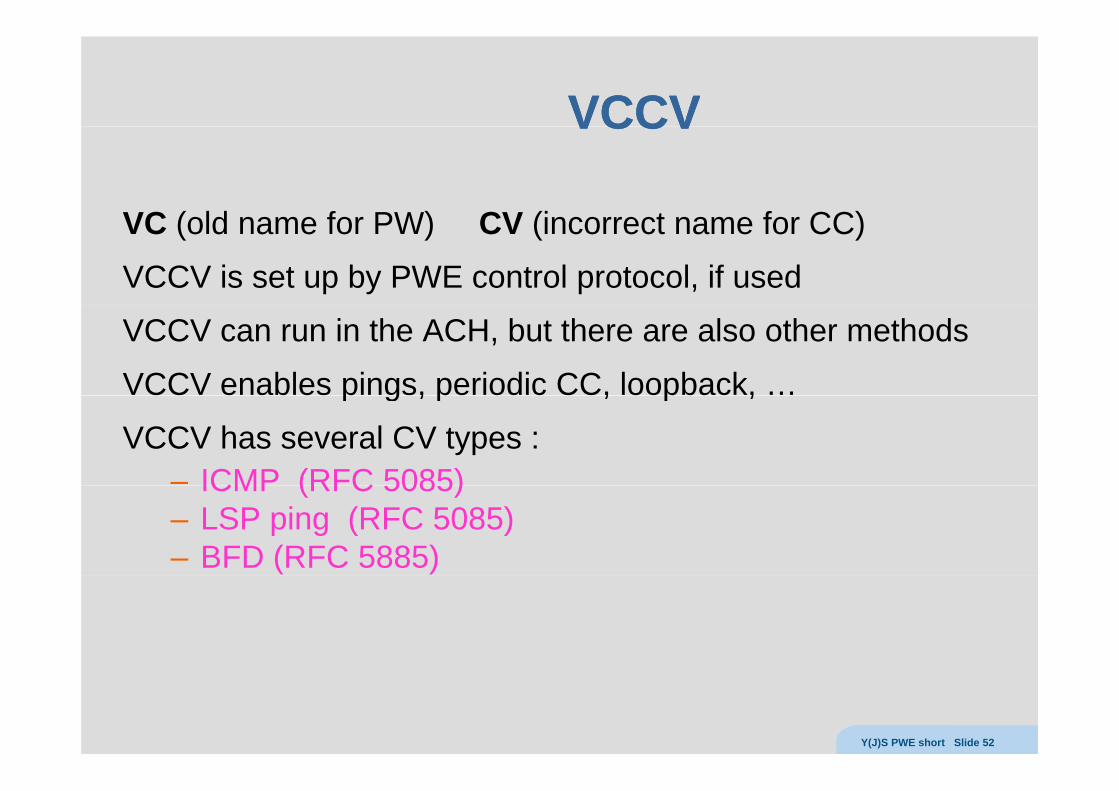
VC ( ld f PW) CV (i t f CC)VC (old name for PW) CV (incorrect name for CC)
VCCV is set up by PWE control protocol, if used
VCCV can run in the ACH, but there are also other methods
VCCV enables pings, periodic CC, loopback, …p g , p , p ,
VCCV has several CV types :– ICMP (RFC 5085)ICMP (RFC 5085)– LSP ping (RFC 5085)– BFD (RFC 5885)
Y(J)S PWE short Slide 52
PWE control protocolPWE control protocol
Y(J)S PWE short Slide 53
PWE (Martini) control protocolPWE (Martini) control protocolPWE (Martini) control protocolPWE (Martini) control protocol
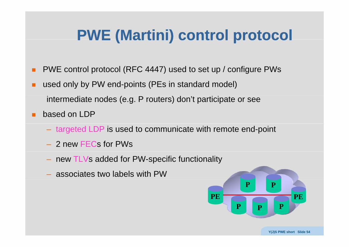
PWE t l t l (RFC 4447) d t t / fi PWPWE control protocol (RFC 4447) used to set up / configure PWs
used only by PW end-points (PEs in standard model)
intermediate nodes (e.g. P routers) don’t participate or see
based on LDP
– targeted LDP is used to communicate with remote end-point
– 2 new FECs for PWs
– new TLVs added for PW-specific functionality
– associates two labels with PW
PEPEP P
P P
PP P P
Y(J)S PWE short Slide 54
PWE controlPWE controla PW is a bidirectional entity (two LSPs in opposite directions)
PW t t f da PW connects two forwarders
2 different LDP TLVs can be usedPWid FEC (128)– PWid FEC (128)
– Generalized ID FEC (129)
FEC 128– both end-points of PW must be provisioned with a unique (32b) value– each PW end-point independently initiates LSP set up– LSPs bound together into a single PW
FEC 129– used when autodiscovering PW end-points– each end-point has attachment identifier (AI) …
Y(J)S PWE short Slide 55
Generalized IDGeneralized IDfor each forwarder we have a PE-unique Attachment Identifier (AI)
<PE, AI> must be globally unique, g y qfrequently useful to group a set of forwarders into a attachment group
where PWs may only be set up among members of a group
then Attachment Identifier (AI) consists of – Attachment Group Identifier (AGI) (which is basically a VPN-id)
Attachment Individual Identifier (AII)– Attachment Individual Identifier (AII)the LSPs making up the (two directions of the) PW are
< PE1, (AGI, AII1), PE2, (AGI, AII2) > and PE1, (AGI, AII1), PE2, (AGI, AII2) and< PE2, (AGI, AII2), PE1, (AGI, AII1) >
we also need to definewe also need to define– Source Attachment Identifier (SAI = AGI+SAII)– Target Attachment Identifier (TAI = AGI+TAII)
receiving PE can map TAI uniquely to ACreceiving PE can map TAI uniquely to AC
Y(J)S PWE short Slide 56