Embed Size (px)
Citation preview

PSI3000/3300 Phase Sequence Indicator
INSTRUCTIONMANUAL
MARTINDALEELECTRIC
Trusted by Professionals
GENERAL SAFETY INFORMATION: Always read before proceeding.
WarningThese instructions contain both information and warnings that are necessary for the safe operation and maintenance of this product. It isrecommended that you read the instructions carefully and ensure that the contentsare fully understood. Failure to understand and to comply with the warnings andinstructions can result in serious injury, damage or even death.
In order to avoid the danger of electrical shock, it is important that proper safetymeasures are taken when working with voltages exceeding 30V AC RMS, 42V ACpeak or 60V DC.
This product must only be used by a competent person capable of interpreting theresults under the conditions and for the purposes for which it has beenconstructed. Particular attention should be paid to the Warnings, Precautions andTechnical Specifications. Always check the unit is in good working order beforeuse and that there are no signs of damage to it. Do not use if damaged.
Where applicable other safety measures such as use of protective gloves, gogglesetc. should be employed.
Please keep these instructions for future reference. Updated instructions andproduct information are available at: http://www.martindale-electric.co.uk/instruct
REMEMBER: SAFETY IS NO ACCIDENT
MEANING OF SYMBOLS:
3
Equipment complies with relevant EU Directives
3 Phase AC (Alternating Current)
Equipment protected by Double Insulation (Class II)
Caution - refer to accompanying documents
Caution - risk of electric shock
End of life disposal of this equipment should be in accordance with relevant EU Directives
Thank you for buying one of our products. For safety and fullunderstanding of its benefits please read this manual beforeuse. Technical support is available from 01923 441717 [email protected].
CONTENTS
1 Introduction 11.1 Description 11.2 Unpacking & Inspection 1
2 Product Specific Safety Information 22.1 Precautions 2
3 Operation 43.1 Replacing Fuses 43.2 How it Works 4
4 Maintenance 74.1 Calibration 74.2 Cleaning 74.3 Repair & Service 74.4 Storage Conditions 7
5 Warranty 8
Specifications

1. INTRODUCTION
1.1 InspectionExamine the shipping carton for any sign of damage. Inspect theunit and any accessories for damage. If there is any damage thenconsult your distributor immediately.
You should have the following items:1. Phase Sequence Indicator complete with 3 GS38 1M long
fused prods.2. Crocodile clips x 3 (red, yellow, blue)3. Velcro straps x 24. Instruction manual
Note: These crocodile clips are rated at a higher overvoltagecategory than the PSI3000/3300 unit. Using them DOES NOTraise or improve the overvoltage category of the PSI3000/3300unit.
1.2 DescriptionPhase Sequence Indicator with neon indication and rotating discindication.
Versions available:PSI3000 – Clockwise Rotation PSI3300 – Anti-clockwise Rotation
The units illuminate all phase neons reliably for voltages above100 Volts rms phase to phase.
The motor rotates above 200 Volts rms phase to phase.
The units are rated to: Overvoltage: CAT III 600VOvervoltage: CAT IV 300V1

2. PRODUCT SPECIFIC SAFETY INFORMATION
2.1 PrecautionsThe product has been designed with your safety in mind, butplease pay attention to the following warnings and cautions beforeuse.
Warning Before use check the unit for cracks or any other damage. Makesure the unit is free from dust, grease and moisture. Also check anyassociated leads and accessories for damage. Do not use ifdamaged.
WarningDO NOT USE IN DAMP CONDITIONS
Avoid severe mechanical shock or vibration and extremetemperature.
This unit is designed to test 3 phase voltages of 415V AC and assuch extreme caution is advised when using this instrument.
BE SURE TO KEEP FINGERS BEHIND THE FINGER GUARDS.
After connecting the first lead of the instrument to asupply voltage the un-connected test leads are a safety hazard.They should only be held behind the finger guard.
Extra care should be taken when using this instrument in dimlylit locations or at height.
2
Do not connect this instrument to single phase supplies.
Prove the functionality of this instrument before everyuse on a known live supply.
When replacing a blown fuse in the test leads, be sure to usefuses of the correct size and rating, see 3.1.
Disconnect all test leads from the supply before attempting toreplace blown fuses.
3
3. OPERATION
3.1 Replacing FusesEach prod is fitted with a 600V 0.5A 50KA HRC rated fuse (6x32mm)and can be replaced by unscrewing the prod tip.Replacement fuse: Martindale order code FUSE500 (pack of 3)
3.2 How it Works
TEST A To Prove ContinuityConnect the red, yellow and blue leads of the indicator to thephases R.Y.B. respectively, switch on the supply and, if continuity iscomplete, the three neons R (L1), Y (L2), B (L3) of the indicator willlight as shown in Fig (1) or (5). The OK neon may also light, butshould be ignored for this test.Note: Neutral and earth connections are not tested. The tests willnot simulate your normal usage load.
TEST B To Identify Faulty Line if Continuity is not ProvedThe faulty phase is indicated by one of the three neons lighting, e.g.should the neon marked R light, it indicates that the Red line isfaulty (see Fig 2). Similarly, Yellow and Blue line faults are indicatedby their respective neons being lit (see Figs 3 and 4). When the faulthas been corrected, phase continuity will be indicated as Fig (1) or(5).
TEST C To Identify the Sequence of Phase RotationAccording to the model number, the tester is configured for eitherclockwise (PSI3000) or anti-clockwise (PSI3300) rotation. Firstensure that continuity is complete as test (A). If the phases arise attheir source in the order red, yellow, blue, the motor indicator willrotate in the direction shown by the arrows and the OK light willilluminate as Fig (1). If the phases arise in the order red, blue,
4
yellow, then the motor indicator will rotate in the reverse directionand the OK lamp will not illuminate as Fig (5).
Note:- Fig 1- 5 shows the PSI3000 version with clockwise arrowdirection.
TEST D To Prove Connection of Colour CodingConnect the leads as in test (A) to supply connections at incomingdistribution box when the instrument will indicate the phasesequence as in Fig (1) or (5). If the installation is correct, a similartest at any other distribution box should produce the same indication.If at any individual test point the phase sequence is reversed, it isobvious that one or more of the phase colours have been crossconnected. To rectify this, proceed as follows:
With the instrument in circuit withdraw a fuse (say on the red line) atthe last test point proved correct. The indicator will show which leadis connected to the red line, i.e. if the neon marked Y remains lit, thismeans that the yellow lead of the tester is connected to the redphase of the supply.
Having identified the red supply phase (which is wrongly coded asyellow), interchange the yellow instrument lead with the redinstrument lead. Replace the fuse and note the indication of theinstrument R.Y.B. or R.B.Y. If the correct indication is given, theinstrument lead colours should correspond to the phase colours.Withdrawal of the blue and yellow fuses in turn will be conclusiveproof of correct identification. The phase connections may then becorrected as appropriate.
TEST E To Identify the Phase Colours of Worn, Faded orUnmarked LeadsWhere the phase colour coding is known at the distribution box, but
5

cannot be identified at the test point, proceed as follows:-Connect the leads of the instrument to the three phases under test (theorder is immaterial), and make sure that phase continuity is completeas in test (A). With continuity in all phases, proceed as in test (D).
Note 1: The tester may be used to check 3 phase supplies withphase to phase voltages from 100V to 600V, and frequencies from40Hz to 60Hz.
Note 2: Before and after using the tester, check for correctoperation on a known voltage. The tester and leads should also beperiodically examined for damage to insulation etc. If any damageis evident, the unit should not be used.
L1 L2 L3
Figure 1.Continuity proved with phase
sequence red, yellow, blue
Figure 2.Red Line Faulty
Figure 3.Yellow Line Faulty
Neon Lit.
Neon Extinguished.
R Y B
OK
Correct Rotation
L1 L2 L3 OK L1 L2 L3 OK
L1 L2 L3 OK L1 L2 L3 OK
No Rotation No Rotation
No Rotation Reversed Rotation
Figure 4.Blue Line Faulty
Figure 5.Continuity proved with phase
sequence red, blue, yellow
R Y B R Y B
R Y B R Y B
6
4. MAINTENANCE
4.1 Calibration
To maintain the integrity of measurements made using your
instrument, Martindale Electric recommends that it is returned at
least once a year to an approved Calibration Laboratory for
recalibration and certification.
Martindale Electric is pleased to offer you this service. Please
contact our Service Department for details.
T: 01923 650660
4.2 CleaningThe unit may be cleaned using a soft dry cloth. Do not usemoisture, abrasives, solvents, or detergents, which can beconductive.
4.3 Repair & ServiceThere are no user serviceable parts in this unit other than thosethat may be described in section 3. Return to Martindale Electric iffaulty. Our service department will quote promptly to repair anyfault that occurs outside the guarantee period.
Before the unit is returned, please ensure that you have checked thefuses.
4.4 Storage ConditionsThe instrument should be kept in warm dry conditions away fromdirect sources of heat or sunlight, and in such a manner as topreserve the working life of the unit. It is strongly advised that theunit is not kept in a tool box where other tools may damage it.
7

5. WARRANTY AND LIMITATION OF LIABILITY
This Martindale product is warranted to be free from defects in
material and workmanship under normal use and service. The
warranty period is 2 years and begins on the date of receipt by the
end user. This warranty extends only to the original buyer or end-
user customer, and does not apply to fuses, disposable batteries,
test leads or to any product which, in Martindale’s opinion, has
been misused, altered, neglected, contaminated, or damaged by
accident or abnormal conditions of operation, handling or storage.
Martindale authorised resellers shall extend this warranty on new
and unused products to end-user customers only but have no
authority to extend a greater or different warranty on behalf of
Martindale.
Martindale's warranty obligation is limited, at Martindale's option, to
refund of the purchase price, free of charge repair, or replacement
of a defective product which is returned to Martindale within the
warranty period.
This warranty is the buyer’s sole and exclusive remedy and is in
lieu of all other warranties, expressed or implied, including but not
limited to any implied warranty of merchantability or fitness for a
particular purpose. Martindale shall not be liable for any special,
indirect, incidental or consequential damages or losses, including
loss of data, arising from any cause or theory.
Since some jurisdictions do not allow limitation of the term of an
implied warranty, or exclusion or limitation of incidental or
consequential damages, the limitations and exclusions of this
warranty may not apply to every buyer. If any part of any provision
8

of this warranty is held invalid or unenforceable by a court or other
decision-maker of competent jurisdiction, such holding will not
affect the validity or enforceability of any other provision or other
part of that provision.
Nothing in this statement reduces your statutory rights.
9

USER NOTES
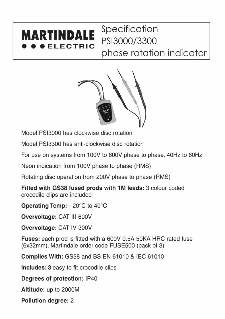
SpecificationPSI3000/3300phase rotation indicator
MARTINDALEELECTRIC
Model PSI3000 has clockwise disc rotation
Model PSI3300 has anti-clockwise disc rotation
For use on systems from 100V to 600V phase to phase, 40Hz to 60Hz
Neon indication from 100V phase to phase (RMS)
Rotating disc operation from 200V phase to phase (RMS)
Fitted with GS38 fused prods with 1M leads: 3 colour codedcrocodile clips are included
Operating Temp: - 20°C to 40°C
Overvoltage: CAT III 600V
Overvoltage: CAT IV 300V
Fuses: each prod is fitted with a 600V 0.5A 50KA HRC rated fuse(6x32mm). Martindale order code FUSE500 (pack of 3)
Complies With: GS38 and BS EN 61010 & IEC 61010
Includes: 3 easy to fit crocodile clips
Degrees of protection: IP40
Altitude: up to 2000M
Pollution degree: 2

� 16th Edition Testers
� Accessories
� Calibration Equipment
� Continuity Testers
� Electricians’ Kits
� Environmental Products
� Full Calibration & Repair Service
� Fuse Finders
� Digital Clamp Meters
� Digital Multimeters
� Labels
� Microwave Leakage Detectors
� Motor Maintenance Equipment
� Multifunction Testers
� Non-trip Loop Testers
� Pat Testers & Accessories
� Phase Rotation Testers
� Proving Units
� Socket Testers
� Thermometers & Probes
� Test Leads
� Voltage Indicators
� Specialist Metrohm Testers (4 & 5kV)
� Specialist Drummond Testers
Check out what else you can get from Martindale:
Martindale Electric Company LimitedMetrohm House, Penfold Trading Estate, Imperial Way, Watford WD24 4YY, UK.
Tel: +44(0)1923 441717 Fax: +44 (0)1923 446900E-mail: [email protected]: www.martindale-electric.co.uk
© Martindale Electric Company Ltd. 2004Registered in England No. 3387451 Rev 1.5 LITPSI3000
Trusted by Professionals


![FEDERAL INTERFACE FILES · 3. File Naming Standards: _[Optional Replacement Indicator].ZIP](https://img.pdfslide.net/doc/110x75/5f45669388d8c816d25917f0/federal-interface-files-3-file-naming-standards-optional-replacement-indicatorzip.jpg)