Embed Size (px)
Citation preview

Supporting interconnection with the PSTN
PCS Network Signaling Using SS7
Y I - B I N G LIN A N D STEVEN K. DEVRIES - ersonal Communications Services (PCS) facilitates the exchange of information (voice, data, video, image, etc.) for mobile users independent of time, location, and access arrangement. To support PCS, mobile communications protocols such as E I W I A Interim Standard 41 (IS-41) 112-161 or Global System for Mobile Communications (GSM) [20] have been defined for PCS Network (PCN) inter-system oper- ations. To support interconnection between a PCN and the Public Switched Telephone Network (PSTN), it is essential that the mobile communicationsprotocol interactswith the PSTN signaling system for mobility management and call control.
This article describes the interactions between a PCN and the PSTN in four aspects:
Interconnection Interfaces -What are the network inter- faces between a PCN and the PSTN? Message Routing - How is the information exchanged among the PCNPSTN network elements?
Mobility Management - How d0es.a PCN recognize the locations of the mobile users? Call Control - How are the calls set up between the mobile users and the wireline users? Mobility management merits further discussion. In a PCN
the current location of a mobile user is usually maintained by a two-level hierarchical strategy with two types of databases. The Home Location Register (HLR) is the location register to which a mobile user identity is assigned for record purposes such as mobile user information (e.g., directory number, profile information, cur- rent location,validation period). The Visitor Location Register (VLR) is the location register other than the HLR used to retrieve infor- mation for handling of calls to or from a visiting mobile user [14]. When a mobile moves from the home PCN to a visited PCN, its location is registered at the VLR of the visited PCN. The VLR then informs the mobile’s HLR of its current location. The details of the registration processwill be discussed in asubsequent section. When a call is delivered to a mobile, the HLR is first queried to find its location (i.e., the VLR corresponding to its current location). The details of location tracking can be found in 1121, and the call setuphelease process is discussed in the section on PCN/PSTN call control using ISUP. Since it is likely that two PCNs are connected through the PSTN, it is important to understand how the PSTN is involved in PCS mobility management.
To address these four aspects, we consider IS-41 as the mobile communications protocol and Signaling System No. 7 (SS7) [2-51 as the PSTN signaling protocol. The IS-41 protocol considered in
this article is based on EIA,TIA IS-41 Revision B. We also describe some potential extensions of the IS-41 protocol based on a draft of IS-41 Revision C. In this article, “IS-41.C” refers to EIAlTIA PN-2991, the Baseline Text Draft 3 9-2-94 of IS-41 Revision C 1191.
,
Signaling System No. 7 ommon Channel Signaling (CCS) is a signaling method which provides control and management in the telephone C network. CCS consists of supervisory functions, address-
ing, and providing call information. A CCS channel conveys messages to initiate and terminate calls, check on the status of some part of the network, and control the amount of traffic allowed.
CCS uses a separate out-of-band signaling network to carry signaling messages. In all figures of this article, the signal links will be represented by dashed lines, and the trunks will be represented by solid links. SS7 is a CCS system developed to satisfy the telephone operating companies’ requirements for an improvement to the earlier signaling systems (which lacked the sophistication required to deliver much more than Plain Old Telephone Service or POTS).
This section provides a brief introduction to the SS7 network architecture and protocol from the perspective of PCN inter- connection. The reader is referred to [ 11 for a more complete SS7 tutorial.
The SS7 Network Architecture Figure 1 illustrates an example of the SS7 signaling network. The figure only shows the parts that involve the interconnec- tion between a PCN and the PSTN. The network consists of three distinct components.
*Service Switching Point (SSP) is a telephone switch inter- connectedbySS7links.TheSSPsperformcallprocessingoncalls that originate, tandem, or terminate at that node. In this article, an SSP in a PCN are called a Mobile Switching Center (MSC).
*Signal Transfer Point (STP) is a switch that relays SS7 mes- sages between network switches and databases. Based on the address fields of the SS7 messages, the STPs route the messages to the correct outgoing signaling links. To meet the stringent reliability requirements, STPs are provisioned in mated pairs.
Service Control Point (SCP) contains databases for pro- viding enhanced services. An SCP accepts queries from an SSP and returns the requested information to the SSP. In mobile
44 1070-9916/95/$04.00 0 1995 IEEE IEEE Personal Communications June 1995

1 ,
applications, an SCP may contain an HLRor a VLR. There are six types of SS7 signaling links. Two
types of the links are introduced in this article. Other types of links can be found in [7].
Each SSP and SCP will have a minimum of one signal link to each STP pair. The signal link is referred to as the Access Link (A-link). The number of A-links between an SSP and an STP pair can be up to 128 though most switch suppli- ers have limited the number to 16.
Signaling links that connect STPs of different networks (e.g., PCN and PSTN in our example) are called Diagonal Links (D-links). D-links are deployed in a quad arrangement with three-way path diversity. The maximum link set size is 64.
The SS7 Protocol The basic parts of the SS7 protocol and the cor- responding OS1 layers are shown in Fig. 2. In the protocol hierarchy, the Operations, Maintenance, and Administration Part ( O W ) and Mobile Appli- cation Part (MAP) are TCAP (i.e., Transaction Capabilities Application Part; to be defined) applications. The details of the OMAP are omit- ted and can be found in [7].
The MAP will be elaborated based on the IS- 41 protocol. The other parts of the SS7 protocol are described below.
*The Message Transfer Part (MTP) consists of three levels corresponding to the OS1 physical layer, data link layer, and network layer, respectively. The MTP Level 1 defines the physical, electrical, and functional characteristics of the signaling links connecting SS7 components. The MTP Level 2 provides reliable transfer of signaling messages between two directly connected signaling points. The MTP Level 3 provides the functions and procedures related to message routing and network manage- ment.
* T h e Signaling Connection Control Par t (SCCP) provides additional functions such as Global Title Translation to the MTP to transfer non-circuit-related signaling information such as PCS registration and cancellation.
*The Transaction Capabilities Application Part (TCAP) provides the ability to exchange information between applications using non-circuit related signaling.
*Integrated Services Digital Network User Part (ISUP) establishes circuit-switched network connections (e.g., call setupirelease). Pass-alongsig- naling service sends the signaling information to each switching point involved in a call connection.
The IS-41 protocol [12, 1.51 is implemented in the MAP as an application of the TCAP. The wireless call setup/release is completed by using the ISUP. The MTP and the SCCP provide rout- ing services between a PCN and the PSTN.
lnterconnection and Message Routing between
PCN and PSTN everal types of interconnections between a PCN and the PSTN have been described in S [8, 171. We describe four types of SS7 inter-
connection between a PCN and the PSTN (specif- ically, the local telephone networks) using SS7:
A-Link A-Link I
I 1
~~------ ~- ~~
W Figure 1. An example of the SS7 network architecture.
OS1 layers The SS7 layers
Application
-/I * I I
ISDN-UP
...__________-.--..-.~-~~
Presentation session
transport
I MTP level 3 I MTP level 2 I Data link I
Physical I MTP level 1 I .~ _ . ~
W Figure 2. The SS7signalingprotocol.~ ~
two for SS7 signaling, and two for trunk (voice circuit) connections [8]. The signaling interfaces rep- resents the physical signaling link connection between a PCN and the PSTN. The SS7 signaling inter- connection methods are described as follows:
A-link signaling interface involves A-links from an MSC to a PSTN STP pair (Figs. 3a and c).
OD-link signaling interface involves D-links from a PCN STP pair to a PSTN STP pair (Figs. 3b and d).
The trunk interfaces represents a physical SS7- supported trunkconnection between aPCN and the PSTN. The types of the SS7 trunk interconnections are described as follows:
*Type 2A with SS7 trunk interface provides connection between a PCN and a PSTN tandem switch. The Type 2A with SS7 interfaces are shown in Figs. 3a and b.
*Type 2B with SS7 trunk interface provides connection between a PCN and a PSTN end office
IEEE Personal Communications June 1995 45

FacilitiesDirective FacilitiesDirective FacilitiesDirective FacilitiesDirective
INVOKE(Last) QUERYWITHPERMISSION RETURN RESULT(Last) CONVERSATIONWITHPERMISSION RETURN ERROR RESPONSE REJECT RESPONSE
MobileOnChannel I INVOKE ]RESPONSE
HandoffMeasurementRequest HandoffMeasurementRequest HandoffMeasurementRequest HandoffMeasurementReauest
- INVOKE(Last) QUERYWITHPERMISSION RETURN RESULT(Last) RESPONSE RETURN ERROR RESPONSE REJECT RESPONSE
RegistrationCancellation RegistrationCancellation RegistrationCancellation RegistrattonCancellation
RegistrationNotification RegistrationNotification RegistrationNotification RegistrationNotification
QualificationRequest QualificationRequest QualificationRequest QualificationRequest
~
INVOKE(Last) QUERYWITHPERMISSION RETURN RESULT(Last) RESPONSE RETURN ERROR RESPONSE REJECT RESPONSE
INVOKE(Last) RETURN RESULT(Last) RETURN ERROR REJECT
QUERYWITHPERMISSION RESPONSE RESPONSE RESPONSE
I A mobile user may also be assigned a Universal Personal Telecommunica- tion (UPT) number. The relationship between the UPT number and the MIN is illustrated in 1221. This article assumes that a mobile user is identified by the MIN.
In IS-41.C, 28 new oper- ations are expected to be included.
INVOKE(Last) RElllRN RESULT(Last) RETURN ERROR REJECT
In IS-41.C, another Package Type called Con- versationWithoutPer- mission will be introduced.
QUERYWITHPERMISSION RESPONSE RESPONSE RESPONSE
Same number of the Cvmponent Types are expected in IS-41 Revision C.
INVOKE(Last) RETURN RESULT(La5t) RETURN ERROR REJECT
ServiceProfileRequest ServiceProfileRequest ServiceProfileRequest ServiceProfileRequest
- - ~ - ~
switch. The Type 2B with SS7 interfaces are shown in Figs. 3 c and d.
Several applications that require calls to be tandemed (e.g., operator services and 800 call setup) are supported by Type 2A with SS7 inter- face, but are not available to Type 2B with SS7 interface.
Both Types 2A and 2B were originally support- ed by multi-frequency (MF) signaling protocols [8]. Other interfaces supported by MF signaling are Type 1, Type 2C for 911 emergency service calls, and Type 2D for operator services. Both 911 calls (Type 2C) and operator services (Type 2D) could be handled along with other types of calls on a Type 2A with SS7 interface. The details of MF signaling for PCN can be found in [SI.
We will show how signaling messages a re deliveredwith the configurationsin Fig. 3. Basically, SS7 message routing is performed at the MTP and the SCCP of a node (SSP, STP, or SCP). At the MTP level, the signaling messages are delivered with the actual destination address. The MTP level receives messages from an adjacent node (SSP, STP, or SCP) or from the TCAP (and thus the SCCP) layer or the ISUP layer of the same node. The Destination Point Code (DPC) of the message uniquely identifies the destination node. Routing to the destination node is determined by the MTP using look-up tables.
In the mobile application, every handset is assigned a Mobile Identification Number (MIN).l When an MIN is dialed, the originating node may not have enough knowledge to identify the actual address of the destination. In this case, the actual destination address is translated by a technique called Global Title Translation (GTT) performed at the SCCP level of the protocol. GTT is supported in
~~
QUERYWITHPERMISSION RESPONSE RESPONSE RESPONSE
IS-41 Revisions B and C, but not in IS-41 Revision A. The ISUP messages for wireless call control (see the section on PCN/PSTN call control using ISUP) are not delivered with GTT. Details of IS- 41 message routing can be found in Appendix B. The appendix describes the fields of an IS-41 message which are used for the routing purpose and how the routing procedure is performed.
Mobility Management Using TCAP
wenty six TCAP operations2 are defined in IS-41 .B [ 131 for three purposes: Inter-MSC T Handoff [15], Automatic Roaming [12], and
Operations, Administration, and Maintenance [16]. The details of handoff and automatic roam- ing (mobility management) alternatives can be found in [21-271.
A TCAP message consists of two portions: the Transaction Portion and the Component Portion. The Transaction Portion specifies the Package Type. Four of the seven Package Types [5, 131 are defined in IS-41.5-B.3
~YwI~PEREIIssIoNNnitiates aTCAP transaction and informs the terminating node that it may end the TCAP transaction.
~
RESPONSE ends the TCAP transaction. CON~E;~SATION~I~~ERMISSION continues a TCAP transaction and informs the destination node that it may end the TCAP transaction. UNIDIRECTIONAL sends information in one direction only with no reply expected. The Component Portion specifies the number
and the types of components (operations) to be performed. Four of the six Component Types are defined in IS-41 Revision B.4 INVOKE (Last) is used to invoke an operation (such as location registration). “Last” indi- cates that the operation is the last component in the Component Part. RE” RESULT (us t ) is used to retum the results of an invoked operation. If a node receives an INVOKE and the operation is executed success- fully, the node shall respond with a RETURN
RETURN ERROR is used to report the unsuccess- ful completion of an invoked operation. For example, the MIN in the INVOKE message is not currently serviced by the HLR. REJECT is used to report the receipt and rejec- tion of an incorrect Package or Component (e.g., ill-formatted). When a node receives a REJECT message, it stops its timer, exits the current task, and performs error recovery. Note that an SS7 transaction alwavs begins
RESULT.
< . ,
with a query message (QueryWithPermission in IS-41), and ends with a response message (Response in IS-41). In IS-41, both the INVOKE and the RETURN RESULT types are “Last” which imply that every IS-41 TCAP message performs exactly one operation. In an IS-41 implementa- tion, we may expect that operat ions such as authentication and registration notification are com- bined into a TCAPmessage. In the remainder of this article, we omit the notation “Last.” All IS-41.B transactions are two-message (a query and a response) transactions except for two cases.
*A TCAP message with the operation FlashRe-
46 IEEE Personal Communications June 1995
- ._I_.̂ ._ -. ~

I /1 r- I /L
Tandem MSC
PSTN
I A
(a) Type 2A with 557 trunk interface supported by a Type 5 A-link signaling interface
(c) Type 2B with 557 trunk interface supported by a Type 5 A-link signaling interface
U Type S (D 1427 links)
Tandem
(b) Type 2A with 557 trunk interface supported by a Type 5 D-link signaling interface
office PSTN
(d) Type 2B with 557 trunk interface supported by a Type S D-link signaling interface
~~-
Figure 3. Types of interconnection between a PCN and the PSTN.
quest has a PackageType UNIDIRECTIONAL. Thismes- sage is sent from the serving MSC to the anchor MSC to convey information for call control. No response is expected from the anchor MSC, and no TCAP transaction is established. This message is defined in IS-41 Revisions B and C, but is not supported in IS-41 Revision A [12].
* A TCAP transaction including the operation Facil it iesDirective consists of three messages exchanges. We will elaborate on this transaction later.
(In IS-41.C, other transactions such as “inter-MSC setup” also involve more than two messages.) IS-41 TCAP uses SCCP Class 0 connectionless service [4] that provides efficient routing without main- taining message sequencing between two or more messages from the same originating node. Message sequencing is implied in the two-message IS-41 transactions. For the three-message IS-41 transac- tions described above, message sequencing is also guaranteed (to be elaborated).
Every IS-41 TCAP transaction accompanies a time- out constraint. Typically, recovery procedures (definedinIS-41.4B [16]) areexecutedwhen a timer expires. For most IS-41 transactions timer expira-
..tion is considered as an error (i.e., the arrival of a RETURN ERROR TCAP message).
We use two examples to illustrate the message
flows of IS-41 TCAP transactions. The TCAP mes- sages described in these examples are summa- rized in Table 1.
Inter-MSC Handoff The inter-MSC handoff procedures are defined in IS-41.2 [15]. We assume that the inter-MSC handoff occurs within a PCN, and the SS7 mes- sages are not delivered to the PSTN. Figure 4 illustrates the IS-41 TCAP message flow for handoff-forward. In this figure, a communicating handset (mobile user) moves out of the base sta- tion served by MSC A. Two transactions are required to perform inter-MSC handoff.
Transaction 7 - MSC A sends a HandoffMea- surementRequest (INVOKE) to the candidate MSC B, and waits for the response from MSC B.
When MSC B receives the HandoffMeasure- mentRequest (INVOKE) ,it selectsacandidate base station BS2for handoff. If nocandidate base station is found, MSC B may exit this transaction. Other- wise, MSC B sends a HandoffMeasurementRe- quest (RETURN RESULT) to MSC A.6
Transadeon 2 - Before this transaction is started, MSC A checks if the handset has made too many handoffs or if inter-MSC trunks are not available.
For simplicity, we express an IS-41 TCAP message as a pair “Opera- tion (Package Type) ” or “Component Type. ”
The result includes the signal quality parameter values.
IEEE Personal Communications June 1995 47

/ _ _ _ _ _ _
@
1;- MSC A exits this transaction, and the hand-off call maybeforcedterminatedif there are toomanyhand- offs or if there are no trunks. Otherwise, MSC A sends a FacilitiesDirective (INVOKE) to MSC B.
When MSC B receives the FacilitiesDirective (INVOKE), it replies with a FacilitiesDirective (RETURN ERROR) if no voice channel is available in BS2.' If BS2 is available to accommodate the call, MSC B replies with a Facil it iesDirective ( R E T " RESULT) * to MSC A.
When MSC A receives the FacilitiesDirective (RETURN), one of the following two events occurs. If the message is a RETURN ERROR, then MSC A executes recovery procedures and exits the trans- action. If the message is a R E T " RESULT, then MSC A sends the handset a handoff order.
After the handset is connected to BS2, MSC B sends a MobileOnChannel (INVOKE) to MSCAand exits this transaction.
When MSC A receives the MobileOnChannel (INVOKE), it connects the call path (trunk) to MSC B and exits this transaction.
. . . . . . _ _ _ _ . _ . . . . . . ~ ~ . . . . ~ ~ ~ ~ ~ . . ~ ~ ~ ~ . . . . . ~ ~ ~ ~ . ~ . . . ~ ,
HandoffMeasurementRequest (INVOKE)
HandoffMeasurementRequest (RETURN RESULT) +
FacilitiesDirective (INVOKE)
FacilitiesDirective (RETURN RESULT)
c
MobileOnChannel (INVOKE)
The IS-41 TCAP messages are delivered through the PCN SS7 signaling links. (See dashed links 1 and 2 in Fig. 4. In this example, an STP is in the signaling path.) Before the handoff, the voice path is (3) ++ (4) ++ (5). If the handoff is successful, the new voice path is ( 3 ) H (4) H (6)
Transaction 1 is a typical two-message IS-41 trans- action . The H a n d off M e a s u r e m e n t Re q u est (INVOKE) is of type QUERYWITHPERMISSION. With this Package Type, MSC A implies that MSC B may end this transaction after the response is sent. The message replied from MSC B is of type RESPONSE, which terminates the transaction.
- (7). The error code of the
message is resource shortage [13].
The result includes the parameters of the selected voice channel.
Transaction 2 is a three-message transaction. Like Transaction 1, Transaction 2is initiated bythe QUERYWITHPERMISSION message FacilitiesDirective (INVOKE) from MSC A. MSC B replies with a CONVERSATIONWITHPERMISSION. The MobileOn- Channel (INVOKE) sent from MSC B to MSC A has a Package Type RESPONSE, which terminates the transaction. Note that the FacilitiesDirective (RETURN) and the MobileOnChannel (INVOKE) must be received by MSC A in the order they are sent. The communication between MSC A, the handset, and MSC B through the air interface guaranteesthat MSCBwillnotsendthe MobileOn- Channel (INVOKE) message before MSC A receives the FacilitiesDirective (RETURN) mes- sage. Thus, number sequencing is achieved with the connectionless service.
At the beginning of Transaction 1, MSC A sets a 7-second timer ( L M M R T ) . I f L M M R T expires before the HandoffMeasurementRe- quest (RETURN) arrives, MSC A exits this trans- action and performs some actions (e.g., blocks the handoff call). If MSC A receives the Hand- OffMeasurementRequest (RETURN) afterLMMRT has expired, then it sends a HandoffMeasure- mentRequest (REJECT) message to inform MSC B that Transaction 1 has been terminated without completion. At the beginning of Transaction 2, MSC A sets a 12-second timer HOT. If H O T expires before the FacilitiesDirective (RETURN) arrives, MSC A exits Transaction 2 and releases associated inter-MSC facilities (see Section 4.3 in [15]). If MSC A receives the RETURN message from MSC B, it stops HOT. MSC A expects to receive subsequent messages from MSC B, and another 7-second timer HMOT is set. If HMOT expires before the MobileOnChannel (INVOKE) arrives, then MSCAexitsTransaction 2 and reclaims the resources.
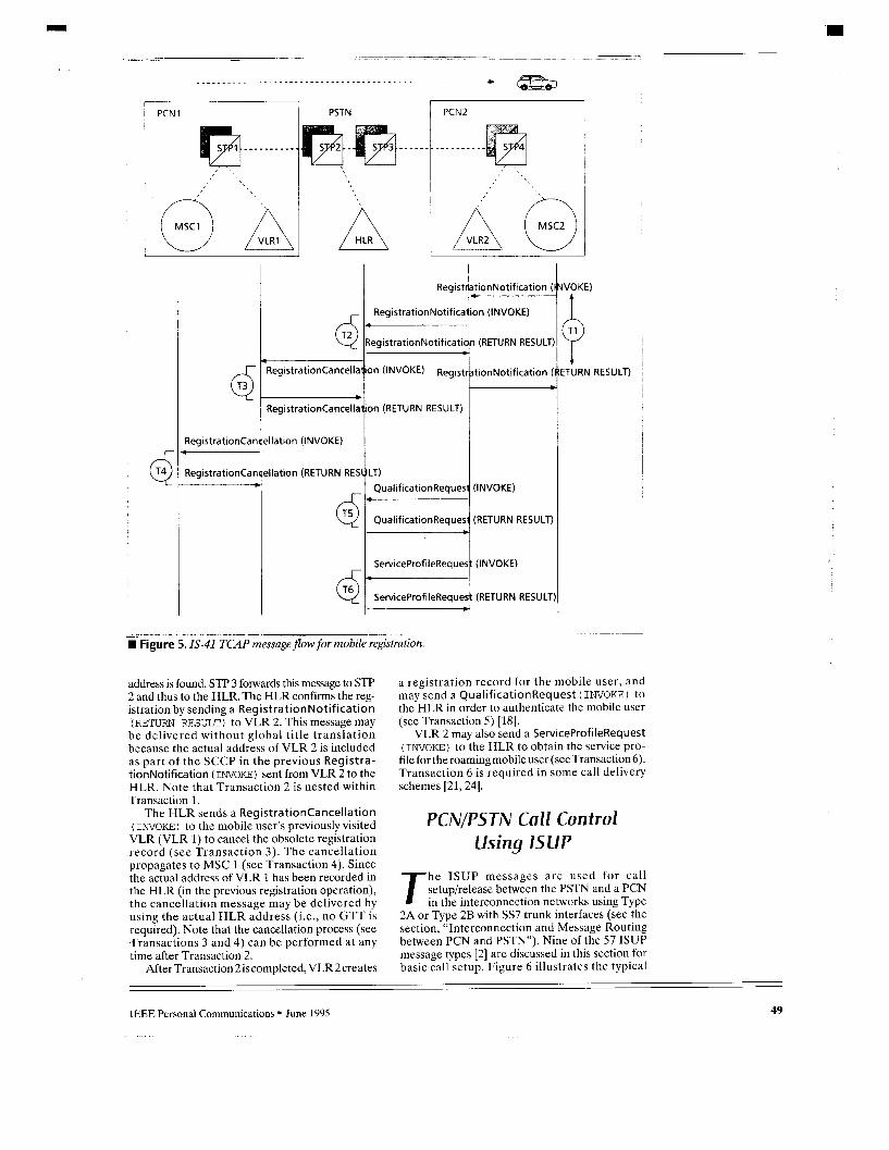
Mobile Registration Figure 5 illustrates the message flow for the regis- tration and validation process as a mobile user roams from PCN 1 to PCN 2. This figure assumes that an MSC and the corresponding VLR are connected by an STP. In reality, i t is more likely that the VLR is collocated with the MSC. The process consists of six two-message TCAP trans- actions. When MSC 2 detects that the mobile user is in its service area, it initiates Transaction 1 witha RegistrationNotification (INVOKE) toitsVLR (VLR 2).
If both MSCs 1 and 2 are served by VLR2, VLR 2 finds that the mobile user had previously registered with an MSC within the domain of VLR 2. In this case, VLR 2 may take no further action other than to record the identity of MSC 1. Otherwise, VLR 2 initiates Transaction 2 by sending a RegistrationNotification (INVOKE) to the mobile user's HLR. Note that this TCAP message is likely to be routed by using the global title translation because VLR 2 may not recog- nize the actual address of the HLR by the mobile user's MIN. Thus, the mobile user's MIN is used as the global title address, and the translation type of the message is marked "3"for Cellular Nation- wide Roaming Services (see Appendix B for more details). Our example assumes that STP 3 will per- formGTT(i.e.,theDPCof themessage points to STP 3). After global title translation, the actual destination
48 IEEE Personal Communications June 1995
1 P C N l
t 6- Registrationcancellat
* RegistrationCancellat
dlation (INVOKE)
illation (RETURN RESULT)
d‘ d
RegistrationNotifica‘ion (INVOKE)
RegistrationNotification (RETURN RESULT)
on (INVOKE)
on (RETURN RESULT)
QualificationRequest (INVOKE)
QualificationReques’ (RETURN RESULT) t
ServiceProfileReques: (INVOKE)
Registrationcan
Registrationcan
- I
ServiceProfileRequesI *
PSTN
(RETURN RESULT
PCN2 I
W Figure 5.7s-41 TCAP message flow for mobile registration.
address is found. STP 3 forwards this message to STF’ 2 and thus to the HLR. The HLR confirms the reg- istration by sending a Registration Not i f ica t ion (RETURN RESULT) to VLR 2. This message may
be delivered without global title translation because the actual address of VLR 2 is included as part of the SCCP in the previous Registra- tionNotification (INVOKE) sent from VLR 2 to the HLR. Note that Transaction 2 is nested within Transaction 1.
The HLR sends a RegistrationCancellation (INVOKE) to the mobile user’s previously visited VLR (VLR 1) to cancel the obsolete registration record (see Transaction 3). The cancellation propagates to MSC 1 (see Transaction 4). Since the actual address of VLR 1 has been recorded in the HLR (in the previous registration operation), the cancellation message may be delivered by using the actual HLR address (Le., no GTT is required). Note that the cancellation process (see Transactions 3 and 4) can be performed at any time after Transaction 2.
After Transaction 2 is completed, VLR 2creates
a registration record for the mobile user, and may send a QualificationRequest (INVOKE) to the HLR in order to authenticate the mobile user (see Transaction 5) [18].
VLR 2 may also send a ServiceProfileRequest (INVOKE) to the HLR to obtain the service pro- file for the roaming mobile user (see Transaction 6). Transaction 6 is required in some call delivery schemes [21,24].
PCNIPSTN Call Control Using I S U P
he ISUP messages a re used for call setuphelease between the PSTN and a PCN T in the interconnection networks using Type
2A or Type 2B with SS7 trunk interfaces (see the section, “Interconnection and Message Routing between PCN and PSTN”). Nine of the 57 ISUP message types [2] are discussed in this section for basic call setup. Figure 6 illustrates the typical
IEEE Personal Communications June 1995 49
. .

t ACM ACM
ANM ANM +
REL Step 5 - REL
L
Step 3
Step 4
Signaling path from PSTN to PCN Signaling path from PCN to PSTN e4bQ+e-.9
~~
m g K 6 . Typical message flow for Type 24 with Sfi land-to-mobile call setup and release involving a tandem switch.
message flow for Type 2A with SS7 land-to-mobile call setuphelease involving a tandem switch (see Fig. 3b). For other interconnection configurations, the message flows between the originating switch and the terminating switch are the same although the sig- naling and trunk paths may be different.
The call setup procedure is described in the following steps [2, 7, 101.
Note that Steps 1-6 of the call setup procedure is general and is not unique to the mobile appli- cations. These steps are presented to provide the reader a complete message flow of wireline-to- wireless call setup.
Step 0 - When an MIN is dialed, the E O notices that the number is for wireless service. The EO sends a query message to obtain the mobile user’s Temporary Local Directory Number (TLDN) [14]. The messages exchanged among switches, VLR, and HLR are TCAP messages described in Fig. 2, IS-41.3 [12]. These messages may be deliv- ered with or without GTT. This example assumes that the EO has the capability to query the HLR. (Otherwise, the MIN must be routed from the EO to a specific switch for location query and call setup [9].)
If the called par ty (mobile user) is busy, the situation is detected at this stage and a busy indication is returned to the calling party (see Fig. 3 in IS-41.3 [12]). If the mobile user has call forwarding or call waiting services, the busy line situation is handled differently (see Figs. 6 and 9
The ISUP messages akcn‘bed in thefollowing steps are delivered by MTP routing. in [12]).
Note that if the called party is a wireline user, the busy line situation is not detected until Step 3.
Step I - After the mobile user’s TLDN is known, the EO sends an Initial Address Message (IAM)9 to the PCN MSC to initiate signaling for trunk setup. The EO marks the circuit busy, and the informa- tion is carried by the IAM. The IAM also indi- cates whether a contimi9 check is required (to be described in the next step). The IAM progresses switch-to-switch via the STPs to the PCN MSC (the message follows the path (1) 4 (2) + (3) + (4) + (5) in Fig. 6). When the IAM is sent, an IAM timer is set at the EO. The EO expects to receive a response from the MSC within the timeout period.
Step 2 (if necessary) - If the IAM sent from the E O to the tandem specifies a continuity check, the selected trunk from the tandem to the EO is checked to ensure a satisfactory transmission path. After the continuity check is successfully completed, a Continuity Message (COT) is sent from the E O to the tandem, and the trunk is set up. The same procedure could be performed when the MSC receives the IAM from the tan- dem.
Step3 - When the IAM arrives at the MSC, the MSC pages the mobile user. One of the following three events occurs:
-The mobile user is connected with another call (the call setup occurs between the end of Step 0 and the end of Step 2). This situation is referred to as Call Collision in Fig. 8, IS-41.3 [12]. Either the call is processed with call forwarding or callwaiting. Or the MSCreturns an RELmessage to the EO (to be described in Step 5) with a cause indicating the busy line.
*If the mobile user is idle, an Address Com- plete Message (ACM) is sent from the MSC to the EO. The message indicates that the routing infor- mation required to complete the call has been received by the MSC. The message also informs the E O of the mobile user information, charge indications, and end-to-end protocol requirements. The MSC provides an audible ring through the setup trunk to the calling party. When the EO receives the ACM, the IAM timer is stopped. The ACM (and other ISUP messages) sent from the MSC to the EO follows the path (5) + (4) + (2) + (3) --;r (1) in Fig. 6.
*Ifthemobile userdoesnot answerthe page, the MSC may redirect the call based on an appropri- ate procedure or return an REL message to the EO (see Fig. 7 in IS-41.3 [12]).
Step 4 - When the mobile user answers the call, an Answer Message (ANM) is sent from the MSC to the EO to indicate that the call has been answered. At this moment, the call is established (through the trunk path (6) and (7) in Fig. 6) and the conversation begins.
I
Step 5 - After the conversation is finished, the call can be disconnected with procedures depend- ing upon who hangs up first. Figure 6 assumes that the calling party hangs up first. (In the next example, we will illustrate the case when the called party hangs up first.) The EO sends a
50 IEEE Personal Communications June 1995
__ __ --

Release Message (REL) to indicate that the specified trunk is being released from the con- nection. The specified trunk is released before the REL is sent, but the trunk is not set idle at the EO until a RLC message (see the next step) is received.
Step 6 - When the MSC receives the REL prop- agated from the EO, it replies with a Release Complete Message (RLC) to confirm that the indicated trunk has been placed in an idle state. After the RLC is sent, the E O (the tandem) waits for 0.5 to 1 second before it seizes the released trunk for the next call.
Figure 7 illustrates the message flow for a call setup from a mobile user to a wireline user. The PSTNiPCN interconnection follows the configu- ration in Fig. 3a. In this example, two Local Exchange Carriers LEC1, LEC2, (local telephone companies) and an Interexchange Carrier IXC (a long distance telephone company) are in the call setup path.
The message flow for call setup is very similar to the previous example except that an Exit mes- sage (EXM) is sent from Tandem 1 to the MSC to indicate that SS7 call setup information has suc- cessfully progressed to the IXC. The EXM is sent to the MSC when Tandem 1 has received an ACM, ANM or REL from the IXC or when an EXM timer expires at Tandem 1. (Our example assumes that the EXM timer expires first.) The timer is set after an IAM is sent from Tandem 1 to the IXC. The sending of the EXM does not affect the com- pletion of any continuity check required on the trunkbetween theMSCandTandem 1 .0n theother hand, if a COT code “continuity check failed” is received for this trunk, the EXM is not sent to the MSC.
The call release procedure in this example assumes that the called party hangs up first, which is different from the previous example. When the called party (the wireline user in this example) hangs up the phone, a Suspend Mes- sage (SUS) is sent from the E O at LEC2 to the MSC to indicate that the called party has discon- nected. The EO expects one of the following two events to occur within a timeout period (14-16 seconds).
An RELfrom the MSCis received by the EO. The EO disconnects the trunk. The called party goes back off-hook. The connection continues, and a Resume Mes- sage ( R E S ) is s e n t f r o m t h e E O t o t h e MSC (not shown in Fig. 7). The SUS timer is stopped. If the SUS timer expires, the E O disconnects
the trunk, and an REL is sent to the MSC. Upon the receipt of the SUS, the MSC expects one of the following three events to occur within a time- out period (10-32 seconds).
The calling party hangs up. The MSC sends an REL to the EO and disconnects the trunk. An REL (from the EO) arrives at the MSC. The MSC disconnects the trunk. An RES (from the EO) arrives at the MSC. The SUS timer is stopped and the connection con-
If the SUS timer expires, the MSC disconnects .. tinues.
the trunk.
1 I
I Conversation I
_ _ _ _ - ~ _ _ - _ _ _ _ -.
Figure 7. Typical messageflow for Type 2A with SS7mobile-to-land call setup and release involving a tandem switch.
Conclusions and Further Reading
e have discussed the SS7-supported interactions between PSTN and PCN. W Specifically, we assumed that the mobile
communications protocol is IS-41. The purpose of this article is to provide a quick overview of the wireless-related signaling.
We described two types of SS7-supported trunk connections, and two types of signaling links between a PCN and the PSTN. If the trunk is connected from the PCN to a PSTN end office, then 911 calls and operator services may not be supported. These services only are supportedvia the PCN trunkconnected to a PSTN access tandem. The reader is referred to [8, 171 for more details.
All messages for mobility management are implemented by the TCAP of SS7. Signaling mes- sages related to call setupirelease are implement- ed by the ISUP of SS7. All signaling messages are routed between PCN and PSTN by the MTP and SCCP of the SS7 protocols.
If the actual destination address is known, the IS-41 TCAP messages a re delivered without global title translation. All ISUP messages for call control are delivered without global title translation. For IS-41 TCAP messages using the mobile users’ MINs, the actual destination addresses may not be known. The destination addresses are translated by the SCCP using global title transla- tion. The reader is referred to [6,9, 111 for fur- ther reading.
IS-41 mobility management is implemented by TCAP with efficient connectionless service (i.e.,
IEEE Personal Communications June 1995 51

out-of-order message delivery). Message sequenc- ing is guaranteed by the simple two-message (a query and a response) TCAP transactions. The reader is referred to [ 12, 15, 19) for further reading.
Call setup/release between a PCN and the PSTN follows standard ISUP procedures.
In the PSTN’s view, PCN call control is similar to other applications such as 800 service. The reader is referred to [6, 101 for further reading.
Acknowledgment The professional review process provided by Hamid Ahmadi is highly appreciated. Li-Fung Chang, Zheng Chen, Robert Ephraim, Dipak Ghosal, Chris Holmgren, Don Lukacs, Bob Schaefer, Howard Sherry, Ding G. Wang, Fu-Lin Wu, and the anony- mous reviewer provided valuable comments to improve the quality of this article.
References [11 A. R. Modarressi. and R. A. Skoog. Signaling System No. 7: A Tutorial,
IEEE Commun. Mag., vol. 28, no 7, July 1990. [21 ANSI, American national standard for telecommunications - Signaling
system number 7: Integrated services digital network (ISDN) user part, Issue 2, Rev. 2, Technical Report ANSI 11.1 13, ANSI, 1992.
[31 ANSI, American national standard for telecommunications - Sig- naling system number 7: Message transfer part (MTP), Issue 2, Rev. 2, Technical Report ANSI 11.1 11, ANSI, 1992.
(41 ANSI, American national standard for telecommunications - Sig- nal ing system number 7: Signaling connect ion control part (SCCP). Issue 2, Rev. 2, Technical Report ANSI 11.1 12, ANSI, 1992
151 ANSI, American national standard for telecommunications - Sig- naling system number 7. Transaction capabilities application part (TUP). Issue 2, Rev. 2, Technical Report ANSI T1.114. ANSI, 1992.
161 Bellcore Bell Communications Research specification of signaling system number 7, Issue 2, Technical Report TR-NWT-000246, Bellcore. 1991
[71 Bellcore. Common channel signaling network interface specifica- tion supporting network interconnection, message transfer part, and integrated services digital network user part, Issue 2, Techni- cal Report TR-TSV-000905, Bellcore, 1993.
181 Bellcore. Compatibility information for interconnection of a wireless services provider and a local exchange carrier network, Issue 2, Technical Report TR-NPL-000145. Bellcore, 1993.
[91 Bellcore, PCS Access services interface specification in support of PCS routing service. PCS home database service, and PCS IS-41 message transport service. Issue 1, Technical Report TA-TSV- 001411, Bellcore. 1993.
[ lo1 Bellcore. CCS Network Interface Specification Supporting Wireless Services Providers, Issue 1, Technical Report GR-1434-CORE. Bellcore, 1994.
11 11 Bellcore. LSSGR: Common Channel Signaling Section 6.5. Techni- cal Report GR-606-CORE, Bellcore. 1994.
I1 21 ElAITlA Cellular radio-telecommunications intersystem operations:
Automatic roaming, Technical Report 15-41.3-8. EIAITIA. 1991. [131 EIAITIA. Cellular radio-telecommunications intersystem opera-
tions: Data communications.Technica1 ReportlS-41.5-6, EIMIA, 1991 [14] ElMIA. Cellular radio-telecommunications intersystem operations:
Functional overview. Technical Report IS-41 1-6, EIMIA. 1991 [151 EIAITIA, Cellular radio-telecommunications intersystem operations:
Intersystem handoff, Technical Report IS-41.2-E. EIAITIA, 1991 1161 EIAITIA, Cellular radio-telecommunications intersystem opera-
tions Operations. administration. and maintenance. Technical Report IS-41.4-6. EIMIA. 1991
11 71 EIMIA. Cellular radio telecommunications interfacesstandard. Tech- nical Report 15-93, EIAITIA. 1993
[181 EIAITIA. Cellular radiotelecommunications intersystem operations authentication. signaling message encryption and voice privacy. Technical Report TSB-51, EIAITIA, 1993.
[191 EIAITIA, Cellular Intersystem Operations - Baseline Text Draft 3 9-2-94 (15-41 Rev. C). Technical Report PN-2991, EIAITIA, 1994
[201 M. Mouly and M.-B. Pautet. The GSM System for Mobile Communi- cations, M Mouly. 49 rue Louise Bruneau, Palaiseau, France, 1992.
[211 R. Jain e t al.. “A caching strategy t o reduce network impacts of PCS.”lEEEJSAC,vol. 12, no.8. 1994, pp. 1434-1445.
1221 5 Mohan and R Jain, Two user location strategies for personal communications services IPCS). IEEE Personal Commun.. vol. 1. no. 1, 1 Q 1994, pp. 42-50
[231 S. Tekinaty and B. Ja bbari, ”Handover policies and channel assignment strategiesin mobilecellularnetworks.”IEEECommun. Mag., vol 29, no 11, Nov. 1991.
I241 Y:B. Lin. “Determining the user locations for personal communi- cations networks,” IEEE Trans. Veh. Technol.. vol. 43, no. 3, 1994. pp. 466-473.
1251 Y -B. Lin, and A Noerpel. “Implicit Deregistration in a PCS Network.” IEEE Trans Veh Technol , vol 43. no. 4, 1994, pp. 1006-1010.
[26]Y -6. Lin. S Mohan, and A Noerpel. “Queueing Priority Channel Assign- ment Strategies for Handoff and Initial Access fora PCS Network.” IEEE Trans. Veh Technol , vol 43. no. 3, 1994. pp. 704-712
[27] Y -B. Lin, S . Mohan,and A. Noerpel. “Channel Assignment Strate- gies for Hand-off and Initial Access for a PCS Network.” IEEE Pers. Commun , vol 1, no. 3. 3 0 1994, pp. 47-56
Biographies YI-BING LIN received a B S E E. from National Cheng Kung University in 1983. and a Ph.D in computer science from the University of Wash- ington in 1990. Since then, he has been w i th the Applied Research Area at Bellcore. Morristown. New Jersey. His current research inter- ests include design and analysis of personal communications services network, distributed simulation, and performance modeling. He i s a subject area editor of the Journal o f Parallel and Distributed Computing, an associate editor of the International Journal in Computer Simulation, an associateeditor of SIMULATION magazine. a memberof theeditorial board of the lnternationallournalof Communications, a member of the editorial board of Computer Simulation Modeling and Analysis, program chair for the 8th Workshop on Distributed and Parallel Simulation, and Gen- eral Chair for the 9th Workshop on Distributed and Parallel Simula- tion. Heis an adjunct research fellow at the Centerforlelecommunications Research, National Chiao-Tung University, Taiwan. R. 0. C.
STEVEN K. DE VRIES has been involved with the 557 protocol since 1985 as a technical manager and a network planner for Illinois Bell. Since 1991 he has been an instructor in the Intelligent Network district at Bellcore TEC in Lisle. Illinois, where he teaches various 557, network, and wireless courses.
AC Authentication Center ACM Address Complete Message ANM Answer Message CCS Common Channel Signaling COT Continuity Message DPC Destination Point Code EIR Equipment Identification
EO End Office EXM Exit Message GT Global Title G7T Global Title Translation HLR Home Location Register IAM Initial Address Message IS-41 EIA/TIA Interim Standard:
Register
Cellular Radio- Telecommunications Inter-System Operations
ISUP Integrated Services Digital Network User Part
Appendix A - Acronym List IXC Interexchange Carrier LEC Local Exchange Carrier MAP Mobile Application Part MF Multi-frequency Signaling MSC Mobile Switching Center MTP Message Transfer Part OMAP Operations, Maintenance,
Administration Part OPC Originating Point Code
OS1 Open System Interconnection PCN PCS Network PCS Personal Communications
PSTN Public Switched Telephone
REL Release Message RES Resume Message RI Routing Indicator Code RLC Release Complete Message SAC Service Access Code
Services
Network
SIC SCCP
SCP SLS SPC SSP ss7 SSN STP sus TCAP
TLDN
UDT UDTS UPT
VLR
Service Indicator Code Signaling Connection Control
Service Control Point Signaling Link Selection Signaling Point Code Service Switching Point Signaling System No. 7 Subsystem Number Signaling Transfer Point Suspend Message Transaction Capabilities
Application Part Temporary Local Directory
Number UnitData UnitData Service Universal Personal
Visitor Location Register
Part
Telecommunication
52 IEEE Personal Communications June 1995
1 .
Appendix B - IS-47 Message Routing
RI = 1
GT ind. = 0
lS-47 MTPISCCP
Address
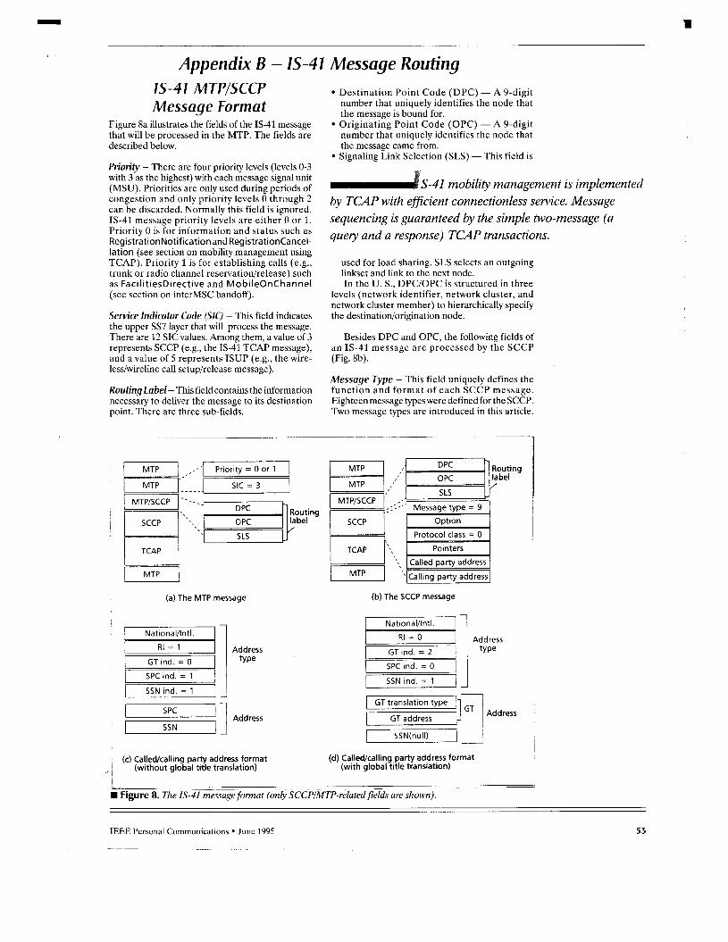
Message Format Figure 8a illustrates the fields of the IS-41 message that will be processed in the MTP. The fields are described below.
Priority - There are four priority levels (levels 0-3 with 3 as the highest) with each message signal unit (MSU). Priorities are only used during periods of congestion and only priority levels 0 through 2 can be discarded. Normally this field is ignored. IS-41 message priority levels are either 0 or 1. Priority 0 is for information and status such as RegistrationNotification and Registrationcancel- lation (see section on mobility management using TCAP). Priority 1 is for establishing calls (e.g., trunk or radio channel reservation/release) such as FacilitiesDirective and MobileOnChannel (see section on interMSC handoff).
Semke lndicator Code (SKI - This field indicates the upper SS7 layer that will process the message. There are 12 SIC values. Among them, a value of 3 represents SCCP (e.g., the IS-41 TCAP message), and a value of 5 represents ISUP (e.g., the wire- lesdwireline call setuphelease message).
Routing Label- This field contains the information necessary to deliver the message to its destination point. There are three sub-fields.
Destination Point Code (DPC) - A 9-digit number that uniquely identifies the node that the message is bound for. Originating Point Code (OPC) - A 9-digit number that uniquely identifies the node that the message came from. Signaling Link Selection (SLS) - This field is
S-41 mobility management is implemented by TCAP with ejficient connectionless service. Message sequencing is guaranteed by the simple two-message (a quely and a response) TCAP transactions.
used for load sharing. SLS selects an outgoing linkset and link to the next node. In the U. S., DPC/OPC is structured in three
levels (network identifier, network cluster, and network cluster member) to hierarchically specify the destinationiorigination node.
Besides DPC and OPC, the following fields of an IS-41 message are processed by the SCCP (Fig. 8b).
Message Type - This field uniquely defines the function and format of each SCCP message. Eighteen message types were defined for the SCCP. Two message types are introduced in this article.
-,,' Priority = 0 or 1
SIC = 3
- - _ ing
j s c c p 1 ' . . . \ .
[ T I (b) The SCCP message (a) The MTP message
- .1 National/lntl. I
SPC ind. = 1
SSN ind. = 1
SPC
SSN Address
I I I
i Address RI = 0
GT ind. = 2
SPC ind. = 0
SSN ind. = 1
GT translation type ' y D q GT address Address
(c) Calledlcalling party address format (without global title translation)
(d) Called/calling party address format (with global title translation)
1 ~
~- - ~ _- ~
W Figure 8 The IS-41 message format (only SCCPMTP-related fields are shown).
IEEE Personal Communications June 1995 53

TCAP
1 Construct UnitData
and set
myeY return
R I = l
No Yes
U
W Figure 9. The SCCP routingprocedures for IS-41 messages.
The normal IS-41 messages are of type 9 (Unit- DaTa or UDT). The SCCP returns a UnitDaTa Service message (UDTS; SCCP message type 10) when a received UDT message cannot be deliv- ered to the specified destination and has the “return message on error” option set. (See the Option field.)
Option - This field is used to decide whether to “return” on error or not. Rulesfor selecting the option values are not defined in IS-41.
Protocol Class - The SCCP provides four classes of connection/connectionless service. The IS-41 messages are supported by the basic connection- less service (Class 0 service). This service does not provide for segmenting/reassembling, flow control or in-sequence delivery.
Note that with the segmenting/reassembling function, a message exceeding 255 bytes is seg- mented into more than one SCCP data transfer message. When the destination SCCP receives these messages, it reassembles the original message for delivery to the destination SCCP user. Although the segmentindreassembling function is not used in the IS-41 standard, we expect that this function (i.e., Class 1 service) maybe required in some IS-41 imple- mentations where long user profile messages are exchanged.
With in-sequence delivery, the SCCP sets the signal link selection (SLS) code to the samevalue for all messages in the message stream. IS-41 messages
do not require in-sequence delivery. We have shown how in-sequence delivery is guaranteed in IS-41 trans- actions.
Pointers - These fields point to the beginning of the called, calling, and data fields.
CalZed/Calling Party Address - These fields have a length indicator and the following sub-fields (Figs. 8 c and d).
Address Indicator - This field indicates the type of address information contained in the called/call- ing party, as follows: National/International - indicates whether the address coding is based on the U.S. stan- dard or the international standard. RoutingIndicator-(RI) identifieswhich address element should be used for routing. If RI = 0, the routing uses the global title in the address. If RI = 1, the routing uses DPC (in the routing label) and the subsystem number (to be elabo- rated) in the called party. Global Title Indicator - There are four num- bers assigned for U.S. networks. IS-41 messages use two of the four types: Code 0 indicates that no global title is included, and Code 2 indicates that global title includes translation type only (i.e., the GTT is performed by using the GT translation type and the GT address; see the address field). Point CodeIndicator-Thevalue 1 indicates that the address contains a signaling point code. Subsystem Indicator-Thevalue 1 indicates that the address contains a subsystem number. When aglobal title is used, the address should also contain a subsystem number, and thus the sub- system indicator is 1.
Address - This field is of variable length. The various elements, when provided, occur in the order described below.
7 ) Signaling Point Code (SPC) - The code has the same format as OPCIDPC. When an originat- ing node sends an IS-41 message with a global title, the OPC of the message is replaced by the address of the STP that performs the G’IT. Thus, the SCCP calling party address field should include the SPC and the SSN of the originating node.
2) Global Title - The IS-41 messages use type 2 (see global title indicator field) global title trans- lation, and the global title consists of two ele- ments.
GT translation type-The translation type isused to direct the message to the appropriate global title translation table. It may also provide the context under which the global title digits are to be interpreted. For example, Code 254 rep- resents 800 service translation. Code 003 (cel- lular nationwide roaming) is used for the IS-41 messages. GT address - The global title address in an IS- 41 message is the 10-digit MIN, or the dialed mobile number. Global title may be used in a calling party address.
This is optional depending on the security require- ments of network interconnections.
3) Subsystem Number (SSN) - This field identifies an SCCP application function at the destination node.
54
_ -
IEEE Personal Communications June 1995

Six of the fourteen SSNs are described in IS-41. SSN 5 Mobile Application Part (MAP) SSN 6 Home Location Register (HLR) SSN 7 Visitor Location Register (VLR) SSN 8 Mobile Switching Center (MSC) SSN 9 Equipment Identification Register (EIR). This code is reserved in IS-41. SSN 10 Authentication Center (AC). This code is reserved in IS-41 B but will be accommodated in IS-41 C. If GTT is required, the address of an IS-41
message always contains a subsystem number. Before GTT, the SSN is encoded 0. After the translation, the actual SSN is given.
The Routing Procedure igure 9 illustrates the SCCP routing for an IS-41 message. We note that this procedure is ageneral routing procedure and is not unique
to IS-41. The message processed by the SCCP may came from the MTP layer or the TCAP layer.
Case 7 The IS-41 message is transferred from the TCAP to the SCCP (Step 1 in Fig. 9). A UDT message is constructed based on the information provid- ed by the MAP/TCAP (Step 4). One of the fol- lowing two events occurs.
Case 1 . 7 - (the DPC is specified at Step 7). There are two possibilities.
Case 1.1.1 (Step 10) The DPC is the node itself. In this case, no G7T is required. Next, the Called Party Field is examined. If RI = 0, it must be a mistake and the Return procedure is invoked (Step 5). The Return procedure returns or dis- cards IS-41 messages (based on the option field) which encounter routing failures and cannot be delivered to their final destination.
If RI = 1, the SSN in the SCCP field is used to determine the local subsystem (e.g., HLR, VLR, and so on). If an appropriate subsystem number is indicated in the message (Step 15), then the message is forwarded to that SSN TCAP layer (e.g., a query is sent to the HLR to access the user profile) at Step 16. Otherwise, an error occurs, and the Return procedure is invoked (Step 5).
all setuplrelease between a PCN and the PSTN follows standard ISUP procedures. In the PSTNs view, PCN call control is similar to other applications such as 800 service.
Case 1.1.2 (Step 10) The DPC is not the node itself.
*Case 1.1.2.1 (Step 1 l)] If the DPC cannot be used to deliver the message, an error occurs. The Return procedure is invoked (Step 5).
*Case 1.1.2.2 (Step 11) If the DPC is appro- priate, the message will be sent to the MTP for delivery. If RI = 1 (Step 12), it implies that G'IT will not be performed. In this case, an appropriate SSN is required (Step 14) before the message is sent to the MTP (Step 17). If RI = 0 at Step 12, GTT is necessary. Since the actual SSN is not expected before the GTT, the message is sent directly to the MTP without checking the SSN status.
Case 7.2 (the DPC is not specified at Step 7) - A GTT is required to find the DPC (and the SSN). This case occurs when an MIN is used to access theHLR.IfRI= 1 atStep8(noGTTrequired),then an error occurs. If RI = 0, GTT is performed at Step 6. Before the translation, the SSN is 0, the translation type is 3 (Cellular Nationwide Roaming Services), and the global title is the 10-digit MIN. Since the GT indicator is 2 for an IS-41 message, the 10-digit MIN and the translation type are used for the translation. After the translation, both the DPC and the SSN are specified, and the routingpro- cedure proceeds to Step 10 (see Case 1.1). If the translation fails (e.g., the MIN is not recognized at Step 9), the Return procedure is invoked.
There are two possibilities.
Case 2 The IS-41 message is transferred from the MTP to the SCCP (Step 2 in Fig. 9). If RI = 1 (Step 3), then the receiving SCCP is the termination point of the message. The action taken is the same as Step 15 at Case 1.1.1 (with RI = 1). If RI = 0, then the G7T is required. The Steps 6 and 9 are performed as in Case 1.2. After the GTT is performed, the situation is the same as Case 1.1 except that RI = 0 when the message is processed at Steps 12 or 13.
IEEE Personal Communications June 1995 55


![Smart Web Management for SS7 VoIP Gateway [호환 모드] · SS7 Model OSI Model Presentation ISUP Transport Session MTP3 Network aspot Network Service Part MTP2 Data Message Transfer](https://img.pdfslide.net/doc/110x75/5ad69ccd7f8b9a6b668bebe5/smart-web-management-for-ss7-voip-gateway-model-osi-model-presentation.jpg)