Embed Size (px)
Citation preview

Copyright © 2013 Pico Technology Ltd. All rights reserved.
PT-104 Data Logger
User's Guide
usbpt104.en r2


IPT-104 Data Logger User's Guide
Copyright © 2013 Pico Technology Ltd. All rights reserved. usbpt104.en r2
Contents....................................................................................................................................11 Introduction
........................................................................................................................................11 Overview
........................................................................................................................................22 Safety warnings
........................................................................................................................................33 Legal information
....................................................................................................................................42 Product information
........................................................................................................................................41 Pack contents
........................................................................................................................................52 Specifications
........................................................................................................................................63 Installing the driver
........................................................................................................................................64 Connection: USB port
........................................................................................................................................75 Connection: Ethernet port
........................................................................................................................................96 Connection: PRT inputs
........................................................................................................................................107 Setting up
........................................................................................................................................128 The back panel
....................................................................................................................................133 Background information
........................................................................................................................................131 Platinum resistance thermometers (PRTs)
....................................................................................................................................15Index


PT-104 Data Logger User's Guide 1
Copyright © 2013 Pico Technology Ltd. All rights reserved. usbpt104.en r2
1 Introduction1.1 Overview
The PT-104 Data Logger is a four-channel, high-resolution temperature converter foruse with PT100 and PT1000 type platinum resistance thermometers (PRTs). It can beused to measure temperature, resistance and voltage.
In PT100, PT1000 and resistance modes, the unit can use a two, three or four-wirecircuit. Four-wire measurement gives the greatest accuracy.
In voltage mode, the input connector can be treated as a differential input withground, or as two single-ended inputs.
Programmer's Guide
All the software that you need for everyday use of the PT-104 Data Logger is suppliedwith the unit. For more advanced applications, you can write your own software.Information on programming is published in a separate guide:
PT-104 Data Logger Programmer's Guide (usbpt104pg.en.pdf)
Introduction2
Copyright © 2013 Pico Technology Ltd. All rights reserved.usbpt104.en r2
1.2 Safety warningsWe strongly recommend that you read the general safety informationbelow before using your product for the first time. If the equipment is notused in the manner specified then the protection provided may beimpaired. This could result in damage to your computer and injury toyourself and others.
DO NOT exceed the maximum input range. The PT-104 Data Logger is designed tomeasure voltages in the range 0 to +2.5 V. Any voltages in excess of ±30 V maycause permanent damage to the unit.
DO NOT use in contact with mains (line) voltages. This product is not designedfor use on circuits carrying mains voltages. Take great care when measuringtemperatures near mains (line-powered) equipment. If in doubt, use a meter to checkthat there is no hazardous AC or DC voltage on the equipment. If a sensor isaccidentally connected to a mains voltage, you risk damage to the converter and yourcomputer, and your computer chassis may become live resulting in injury to yourselfand others.
DO NOT exceed the maximum input voltage range of the device. Incorrectconfiguration or use of the device to measure voltages outside this range can behazardous.
DO NOT rely upon the product's ground connection as a protective safetyearth. If there is any possibility of contact with hazardous voltages, the equipmentunder test must be safely earthed.
DO NOT attempt to repair the unit. The unit contains no user-serviceable parts.Repair or calibration of the unit requires specialised test equipment and must beperformed by Pico Technology or its authorised distributors.

PT-104 Data Logger User's Guide 3
Copyright © 2013 Pico Technology Ltd. All rights reserved. usbpt104.en r2
1.3 Legal informationThe material contained in this release is licensed, not sold. Pico Technology grants alicence to the person who installs this software, subject to the conditions listed below.
Access. The licensee agrees to allow access to this software only to persons who havebeen informed of these conditions and agree to abide by them.
Usage. The software in this release is for use only with Pico products or with datacollected using Pico products.
Copyright. Pico Technology Limited claims the copyright of, and retains the rights to,all material (software, documents etc.) contained in this release. You may copy anddistribute the entire release in its original state, but must not copy individual itemswithin the release other than for backup purposes.
Liability. Pico Technology and its agents shall not be liable for any loss, damage orinjury, howsoever caused, related to the use of Pico Technology equipment orsoftware, unless excluded by statute.
Fitness for purpose. No two applications are the same: Pico Technology cannotguarantee that its equipment or software is suitable for a given application. It is yourresponsibility, therefore, to ensure that the product is suitable for your application.
Mission-critical applications. This software is intended for use on a computer thatmay be running other software products. For this reason, one of the conditions of thelicense is that it excludes usage in mission-critical applications, for example lifesupport systems.
Viruses. This software was continuously monitored for viruses during production.However, you are responsible for virus-checking the software once it is installed.
Support. If you are dissatisfied with the performance of this software, please contactour technical support staff, who will try to fix the problem within a reasonable time. Ifyou are still dissatisfied, please return the product and software to your supplierwithin 14 days of purchase for a full refund.
Upgrades. We provide upgrades, free of charge, from our web site atwww.picotech.com. We reserve the right to charge for updates or replacements sentout on physical media.
Trademarks. Pico Technology Limited, PicoScope and PicoLog, are trademarks of PicoTechnology, registered in the United Kingdom and other countries. Windows XP,Windows Vista and Windows 7 are trademarks of Microsoft Corporation.

Product information4
Copyright © 2013 Pico Technology Ltd. All rights reserved.usbpt104.en r2
2 Product information2.1 Pack contents
Please check that your PT-104 pack (order code PP682) contains the following items:
Quantity Reorder code Description
1 PP682 PT-104 Data Logger
1 DO112 USB Installation Guide
1 MI106 USB lead
1 DI025 Software and Reference CD
1 TA076 Ethernet patch cable

PT-104 Data Logger User's Guide 5
Copyright © 2013 Pico Technology Ltd. All rights reserved. usbpt104.en r2
2.2 Specifications
Temperature Resistance Voltage
Sensor PT100*, PT1000 N/A N/A
Range -200 to +800 °C0 to 375 *0 to 10 kΩ
0 to 115 mV0 to 2.5 V*
Linearity 20 ppm 20 ppm 20 ppm
Accuracy @25°C 0.01 °C* 20 ppm*0.2% (0 to 2.5 V)2% (0 to 115 mV)
Temperaturecoefficient 5 ppm/°C 5 ppm/°C 100 ppm/°C
RMS Noise
(using filter)0.01 °C 10 ppm 10 ppm
Resolution 0.001 °C 1 µ 0.156 µV
Conversion TimePer Channel 720 ms
Number of inputs 4
Connectors 4-pin mini-DIN
Input impedance >> 1 M
Overvoltageprotection ±30 V
Output USB or Ethernet
Power Powered by USB or Ethernet:USB 1.1: 5 V ±10% @ <100 mAUSB 2.0: 5 V ±10% @ <200 mA
Ethernet: 48 V ±20% @ <40 mA (< 2 W)
Temperaturerange
20 °C to 30 °C for stated accuracy0 °C to 70 °C operating-20 to +80 °C storage
Humidity range 20% to 90% RH non-condensing, operating5% to 95% RH non-condensing, storage
Dimensions W 135 x L 184 x H 36 mm(5.31 x 7.24 x 1.42 in)
Software
PicoLog data logging software.Drivers for Windows XP SP3/Windows Vista/Windows 7/
Windows 8.Examples for C/C++, Excel, LabVIEW.
Ethernet port Conforms to IEEE 802.3 10Base-T.Compatible with 10/100/1000Base-T networks.
Conforms to IEEE 802.3af Power-over-Ethernet (PoE).
USB port Conforms to USB 2.0 Full-Speed (12 Mbps)
*Quoted accuracy is for options marked

Product information6
Copyright © 2013 Pico Technology Ltd. All rights reserved.usbpt104.en r2
2.3 Installing the driverThe driver is installed automatically when you install the PicoLog software.Alternatively, you can download the driver from our website at http://www.picotech.com.
2.4 Connection: USB portTo use the PT-104 Data Logger, connect its USB port to a USB port on your computerusing the cable provided.
The first time you connect the device, Windows will install the driver and then tell youthat the device is ready for use. You can then run the PicoLog software to start makingmeasurements.

PT-104 Data Logger User's Guide 7
Copyright © 2013 Pico Technology Ltd. All rights reserved. usbpt104.en r2
2.5 Connection: Ethernet portSetup utility
Before connecting to the PT-104 Data Logger's Ethernet port, you must first configurethe Ethernet settings. Proceed as follows:
1. Connect the unit to your computer using the USB port.2. Run the Ethernet Settings utility. There is a shortcut to this utility in the Pico
Technology program group under the Windows Start menu.3. Set the Device Types control to "PT-104 (USB)".4. The serial number of your device should appear in the device list. Click the device
once to select it.5. Set the Enable Ethernet Settings check box.6. Enter the IP address and port that you wish to give the device. You may need to
ask your network manager for an IP address that does not conflict with existingdevices on the network.
7. Click Save.8. You can now either continue to use the PT-104 Data Logger as a USB device, or
unplug the USB cable and reconnect the device using its Ethernet port.

Product information8
Copyright © 2013 Pico Technology Ltd. All rights reserved.usbpt104.en r2
Power-saving tip
If you wish to stop using the PT-104 Data Logger in Ethernet mode, youcan use the Ethernet Settings utility to disable its Ethernet port. Thisreduces the power consumption of the device when used in USB mode.
Ethernet and USB
Do not use the PT-104 Data Logger in USB mode when it is being poweredby Power-over-Ethernet (PoE). This could cause the unit to radiateelectromagnetic energy outside the limits permitted by FCC and EUregulations, and could also cause it to produce spurious measurements. Itwill not, however, cause permanent damage to the unit.
LAN connection
To use the PT-104 Data Logger on a local-area network (LAN), connect it to yournetwork switch or network router using the Ethernet cable provided.
Direct connection
You can also connect the PT-104 Data Logger directly to the network port on yourcomputer. For this connection, you will need to use an Ethernet crossover cable (notsupplied).
Power over Ethernet (PoE)
The PT-104 Data Logger can obtain its power from the Ethernet port as a PoweredDevice (PD) according to the PoE standard. To use this feature, you must connect theunit to Power Sourcing Equipment (PSE) such as a network switch, router or powerinjector that also supports the PoE standard. Any standard Ethernet cable up to 100 m(about 328 ft) in length can be used.

PT-104 Data Logger User's Guide 9
Copyright © 2013 Pico Technology Ltd. All rights reserved. usbpt104.en r2
2.6 Connection: PRT inputsThe PT-104 Data Logger is compatible with PT100 and PT1000 type platinumresistance thermometers (PRTs). Connect each one of these devices to the unit asfollows.
Pin Connections to the PT-104 Data Logger Mini-DIN socket
Pin PT100, PT1000
or Resistance
4-Wire
PT100, PT1000
or Resistance
3-Wire
PT100, PT1000
or Resistance
2-Wire
Differential voltage
1 White Connect to pin 3 Connect to pin 3 Do not connect2 Red Red Red V -3 White White White V +4 Red Red Connect to pin 2 Gnd
Single-ended voltage connection
Single-ended mode allows you to double the number of channels from 4 to 8. It issupported by the driver, so you can use it in your own applications. It is not, however,supported by the PicoLog software.
Connector Channel Pin
11 3
5 2
22 3
6 2
33 3
7 2
44 3
8 2
Note on Differential Voltage Mode
The maximum input voltage range of the PT-104 Data Logger is 2.5 V. Any voltage inexcess of ±30 V on any input pin may cause permanent damage to the unit.
In Differential Voltage Mode, the input connector should be treated as a differentialinput with reference to ground. Both inputs (V+ and V-) must be zero volts or above(it does not matter which input has the higher voltage) and must remain within theinput range. A ground reference connection is also required for correct operation. Theground connection of each mini-DIN socket consists of a 100 resistor to mainsearth/ground through the USB cable outer braiding and the PC chassis.

Product information10
Copyright © 2013 Pico Technology Ltd. All rights reserved.usbpt104.en r2
2.7 Setting upSet up the PT-104 Data Logger as follows:
1. From the File menu in the PicoLog software Recorder, select New settings.The Recording dialog box appears:
2. Click OK. The Sampling Rate dialog box appears:
3. Click OK. The Converter details dialog box appears.
4. From the Converter type drop-down list, select either PT-104 (USB) or PT-104(Ethernet). The dialog box will then show the converter list, as in the followingexamples:

PT-104 Data Logger User's Guide 11
Copyright © 2013 Pico Technology Ltd. All rights reserved. usbpt104.en r2
5. USB connection: Select the device with the correct type and serial number, andclick OK.
Ethernet connection: Any PT-104 Data Logger devices visible to yourcomputer on your local network will appear in the list. Select the device with thecorrect type and IP address, and click OK. If your device does not appear in thelist, type its IP address and port number in the boxes below the list.
When you click OK, the PT-104 Data Logger channels window will appear:
6. In the PT-104 Data Logger channels window, double-click on Ch1 unused.The Edit PT-104 Data Logger Channel dialog box appears:
7. Type in a name for the channel, if required.
8. Select the data type required i.e temperature, resistance or voltage.
9. Select circuit - for PT100, PT1000 and Resistance data types only.
Product information12
Copyright © 2013 Pico Technology Ltd. All rights reserved.usbpt104.en r2
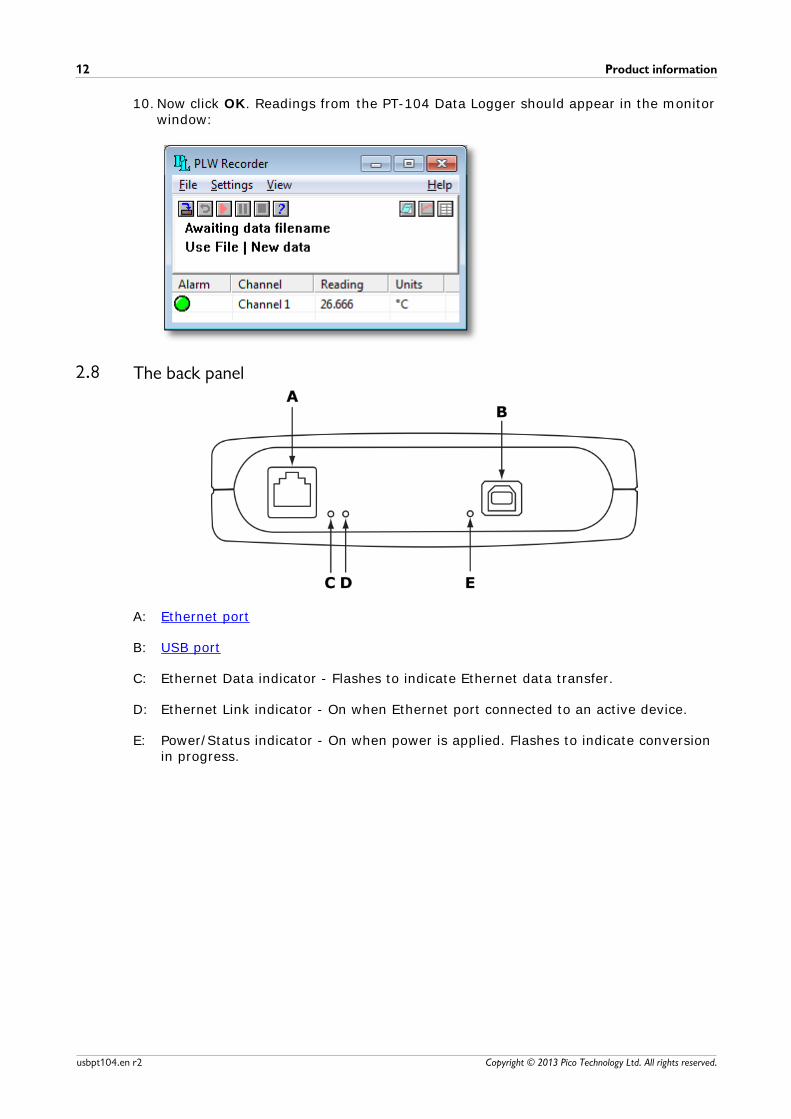
10.Now click OK. Readings from the PT-104 Data Logger should appear in the monitorwindow:
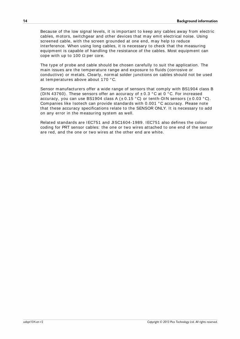
2.8 The back panel
A: Ethernet port
B: USB port
C: Ethernet Data indicator - Flashes to indicate Ethernet data transfer.
D: Ethernet Link indicator - On when Ethernet port connected to an active device.
E: Power/Status indicator - On when power is applied. Flashes to indicate conversionin progress.

PT-104 Data Logger User's Guide 13
Copyright © 2013 Pico Technology Ltd. All rights reserved. usbpt104.en r2
3 Background information3.1 Platinum resistance thermometers (PRTs)
PRTs (Platinum Resistance Thermometers) offer excellent accuracy over a widetemperature range (from -200 °C to 850 °C). Sensors are interchangeable betweendifferent manufacturers, and are available in various accuracy ratings in packages tosuit most applications. Unlike thermocouples, it is not necessary to use special cablesto connect to the sensor.
The principle of operation is to measure the resistance of a platinum element. Themost common type (PT100) has a resistance of 100 at 0 °C and 138.4 at 100 °C.
The relationship between temperature and resistance is approximately linear over asmall temperature range. For example, if you assume that it is linear over the 0 °C to100 °C range, the error at 50 °C is 0.4 °C. For precision measurement, it is necessaryto linearise the resistance to give an accurate temperature. The most recent definitionof the relationship between resistance and temperature is International TemperatureStandard 90 (ITS-90). This linearisation is done automatically with software.
The linearisation equation is:
Rt = R0 (1 + A·t + B·t2 + C·(t-100)·t3)
A = 3.9083 x 10⁻³
B = -5.775 x 10⁻⁷
C = (below 0°C) -4.183 x 10⁻¹²
(above 0°C) 0
For a PT100 sensor, a 1 °C temperature change will cause a 0.384 change inresistance, so even a small error in measurement of the resistance (for example, theresistance of the wires leading to the sensor) can cause a large error in themeasurement of the temperature. For precision work, sensors have four wires - two tocarry the sense current, and two to measure the voltage across the sensor element. Itis also possible to obtain three-wire sensors, although these operate on the (notnecessarily valid) assumption that the resistance of each of the three wires is thesame.
The current through the sensor will cause some heating. For example, a sense currentof 245 µA through a 100 resistor generates 6 µW of heat. If the sensor element isunable to dissipate this heat, it reports an artificially high temperature. This effect canbe reduced by either using a large sensor element, or by making sure that it is in goodthermal contact with its environment.
Using a 1 mA sense current gives a signal of only 100 mV. Because the change inresistance for a degree Celsius is very small, even a small error in the measurement ofthe voltage across the sensor produces a large error in the temperature measurement.For example, a 100 µV voltage measurement error would give a 0.4 °C error in thetemperature reading. Similarly, a 1 µA error in the sense current would give a 0.4 °Ctemperature error.
Background information14
Copyright © 2013 Pico Technology Ltd. All rights reserved.usbpt104.en r2
Because of the low signal levels, it is important to keep any cables away from electriccables, motors, switchgear and other devices that may emit electrical noise. Usingscreened cable, with the screen grounded at one end, may help to reduceinterference. When using long cables, it is necessary to check that the measuringequipment is capable of handling the resistance of the cables. Most equipment cancope with up to 100 per core.
The type of probe and cable should be chosen carefully to suit the application. Themain issues are the temperature range and exposure to fluids (corrosive orconductive) or metals. Clearly, normal solder junctions on cables should not be usedat temperatures above about 170 °C.
Sensor manufacturers offer a wide range of sensors that comply with BS1904 class B(DIN 43760). These sensors offer an accuracy of ±0.3 °C at 0 °C. For increasedaccuracy, you can use BS1904 class A (±0.15 °C) or tenth-DIN sensors (±0.03 °C).Companies like Isotech can provide standards with 0.001 °C accuracy. Please notethat these accuracy specifications relate to the SENSOR ONLY. It is necessary to addon any error in the measuring system as well.
Related standards are IEC751 and JISC1604-1989. IEC751 also defines the colourcoding for PRT sensor cables: the one or two wires attached to one end of the sensorare red, and the one or two wires at the other end are white.

PT-104 Data Logger User's Guide 15
Copyright © 2013 Pico Technology Ltd. All rights reserved. usbpt104.en r2
Index
AAccess 3
Accuracy 5
BBack panel 12
CConnection
Ethernet 7
PRTs 9
USB 6
Connectors 5
Conversion time 5
Copyright 3
DDimensions 5
EEnvironmental conditions 5
Ethernet
connection 7
indicators 12
port 12
FFitness for purpose 3
IIndicators 12
Inputs
impedance 5
number of 5
Installation 6
LLAN connection 7
Legal information 3
Liability 3
Linearity 5
MMains voltages 2
Maximum input range 2
Mission-critical applications 3
NNoise, RMS 5
OOutput 5
Overview 1
Overvoltage protection 5
PPack contents 4
Power indicator 12
Power-over-Ethernet (PoE) 7
PRT
background information 13
connection 9
RRange 5
Repairs 2
Resolution 5
SSafety warnings 2
Sensor 5
Setting up 10
Software 5
Specifications 5
Status indicator 12
Support 3
TTemperature coefficient 5
Trademarks 3
UUpgrades 3
Usage 3
USB
connection 6
port 12

Index16
Copyright © 2013 Pico Technology Ltd. All rights reserved.usbpt104.en r2
VViruses 3

PT-104 Data Logger User's Guide 17
Copyright © 2013 Pico Technology Ltd. All rights reserved. usbpt104.en r2

Pico TechnologyJames House
Colmworth Business ParkST. NEOTS
CambridgeshirePE19 8YP
United KingdomTel: +44 (0) 1480 396 395Fax: +44 (0) 1480 396 296
www.picotech.com
Copyright © 2013 Pico Technology Ltd. All rights reserved.usbpt104.en r2 26.06.13