Embed Size (px)
Citation preview

PTT 205
HEAT AND MASS TRANSFER
Heat Exchangers

Heat transfer equipments:
i) Heat exchangers
ii) Evaporators
iii) Dryers
iv) Agitated vessel
Topic Outline
• Types of heat exchangers
• Log Mean Temperature Different (LMTD)
• Correction Factor of LMTD
• Heat Exchanger Effectiveness
• Fouling Factors
• Design of heat exchanger
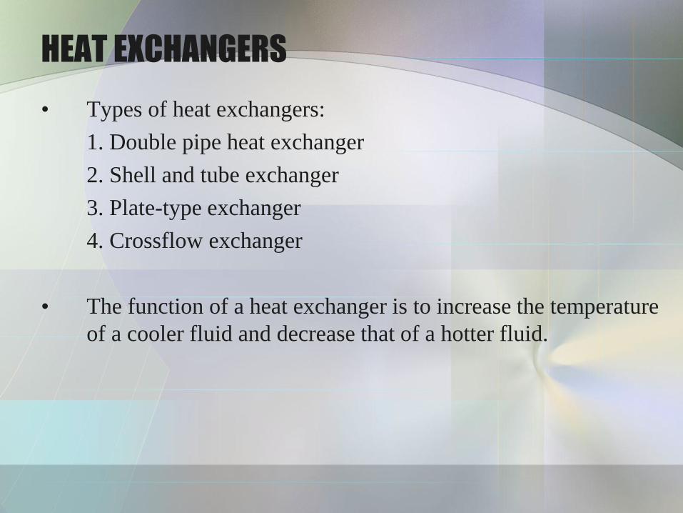
HEAT EXCHANGERS
• Types of heat exchangers:
1. Double pipe heat exchanger
2. Shell and tube exchanger
3. Plate-type exchanger
4. Crossflow exchanger
• The function of a heat exchanger is to increase the temperature
of a cooler fluid and decrease that of a hotter fluid.

1. Double pipe heat exchanger
• The simplest configuration (Fig 1.1)
• One fluid flow through the inside pipe, and the second fluid
flows through the annular space between the outside and the
inside pipe.
• The fluid can be in co-current or countercurrent flow.
• Useful for small flow rates and when not more than 100 – 150
ft2 of surface is required.

Fig. 1.1 Double pipe heat exchanger

2. Shell and Tube Exchanger
• The most important type of exchanger in use in oil refineries and larger chemical processes and is suited for higher-pressure applications.
• Useful for larger flow rates as compared to double pipe heat exchanger.
• The simplest configuration: 1-1 counterflow exchanger (one shell pass and one tube pass) – refer to Figure 1.2.
• consists of a shell (a large pressure vessel) with a bundle of tubes inside it.
• One fluid runs through the tubes, and another fluid flows over the tubes (through the shell) to transfer heat between the two fluids.

• The cold fluid enters and flow inside through all the tubes in parallel in one pass
• The hot fluid enters at the other end and flow counterflow across the outside the tubes in the shell side.
• Cross-baffles – increase the shell side heat transfer coefficient
Fig 1.2 Shell and tube heat exchanger
(1 shell pass and 1 tube passes (1-1 exchanger))
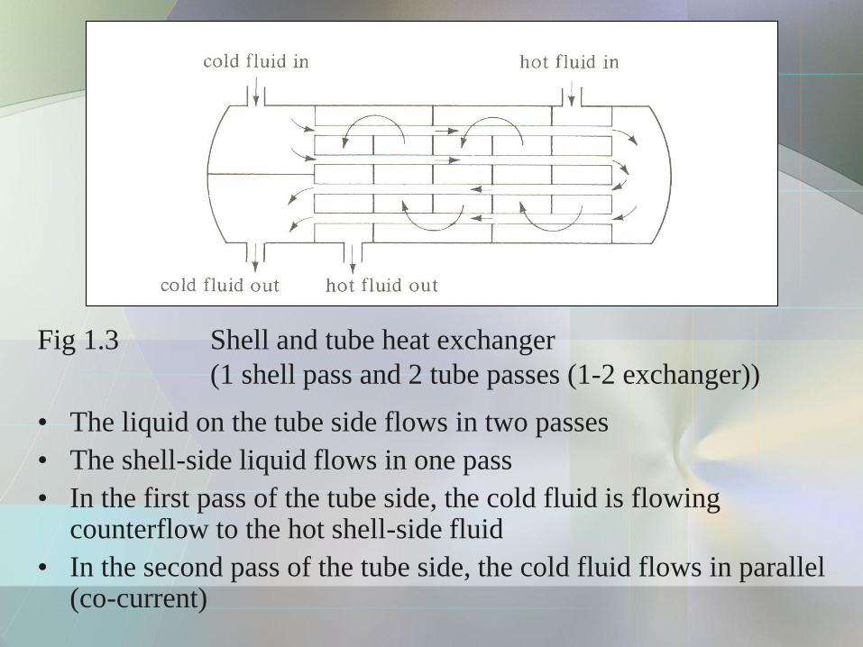
Fig 1.3 Shell and tube heat exchanger
(1 shell pass and 2 tube passes (1-2 exchanger))
• The liquid on the tube side flows in two passes
• The shell-side liquid flows in one pass
• In the first pass of the tube side, the cold fluid is flowing counterflow to the hot shell-side fluid
• In the second pass of the tube side, the cold fluid flows in parallel (co-current)
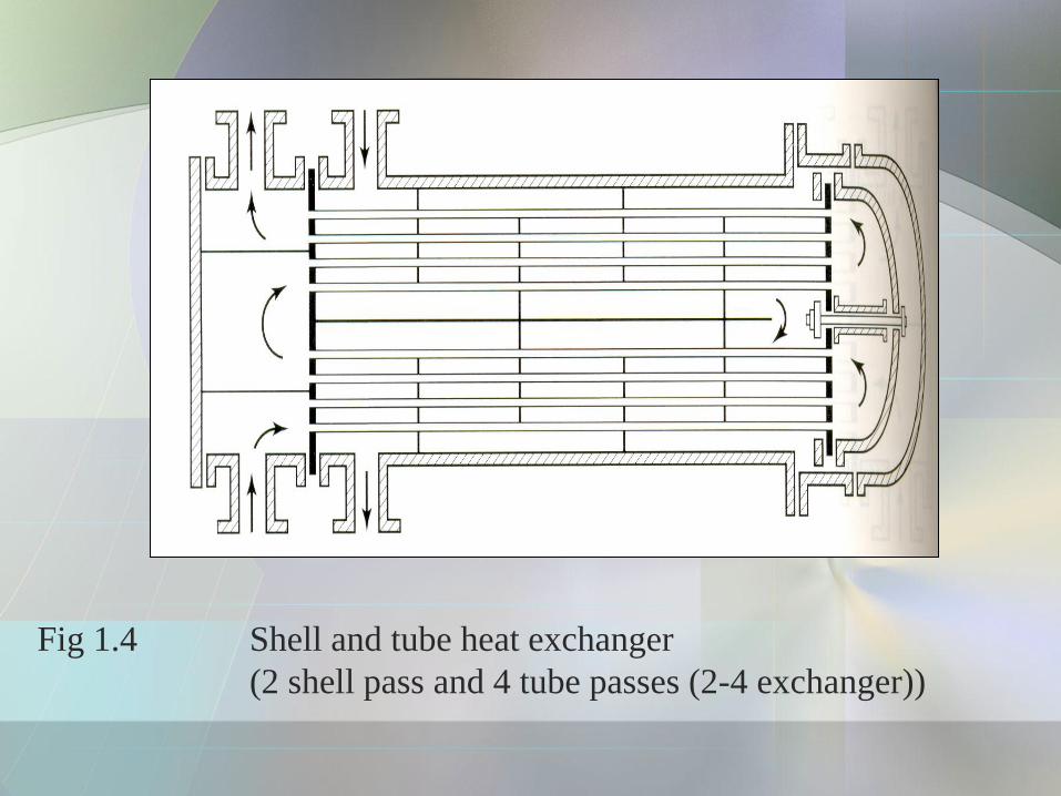
Fig 1.4 Shell and tube heat exchanger
(2 shell pass and 4 tube passes (2-4 exchanger))
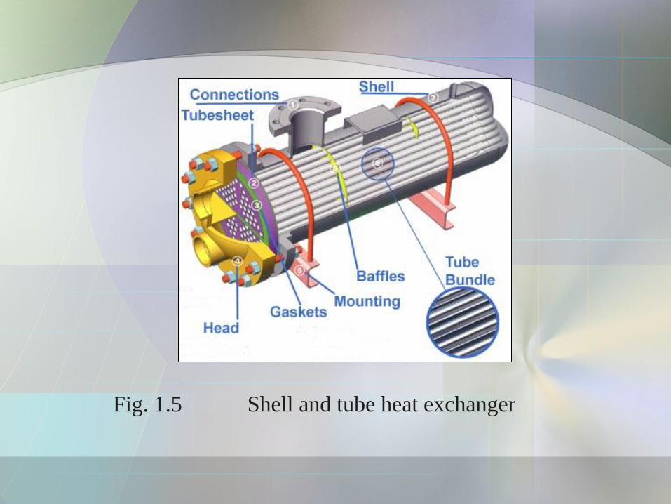
Fig. 1.5 Shell and tube heat exchanger
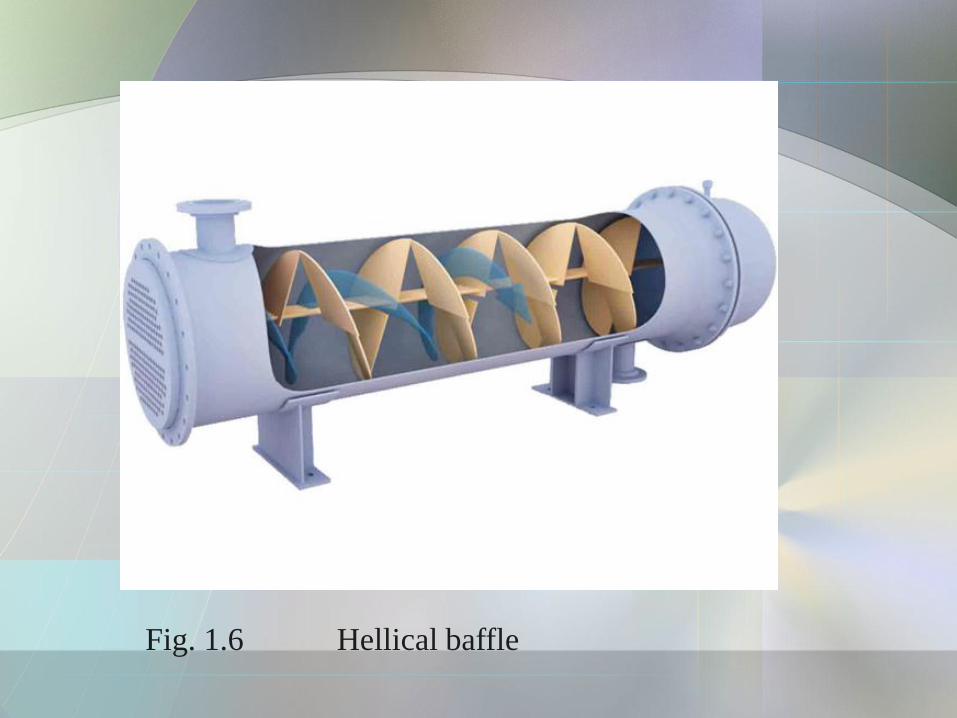
Fig. 1.6 Hellical baffle
3. Plate heat exchanger
• Use metal plates to transfer heat between two fluids
• Consist of many corrugated stainless steel sheets separated by polymer gaskets and clamped in a steel frame.
• The corrugation induce turbulence for improve heat transfer
• The space between plates is equal to the depth of the corrugations (2 - 5 mm)
• The plates are compressed in a rigid frame to create an arrangement of parallel flow channels with alternating hot and cold fluids.
• Major advantage over a conventional heat exchanger in that the fluids are exposed to a much larger surface area because the fluids spread out over the plates.
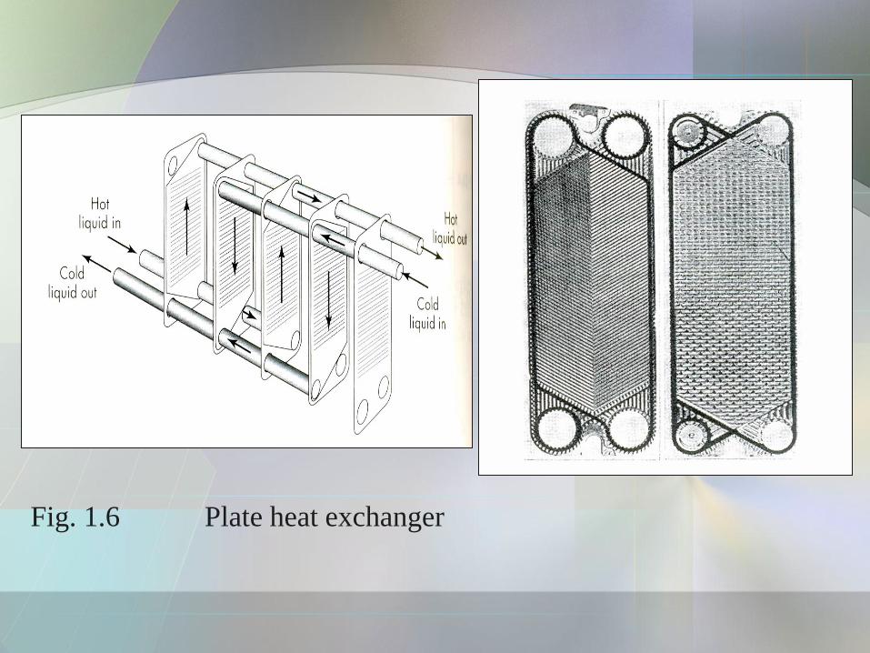
Fig. 1.6 Plate heat exchanger
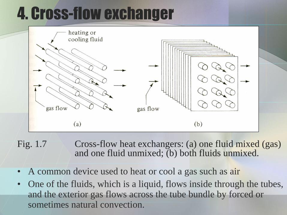
• A common device used to heat or cool a gas such as air
• One of the fluids, which is a liquid, flows inside through the tubes, and the exterior gas flows across the tube bundle by forced or sometimes natural convection.
4. Cross-flow exchanger
Fig. 1.7 Cross-flow heat exchangers: (a) one fluid mixed (gas) and one fluid unmixed; (b) both fluids unmixed.
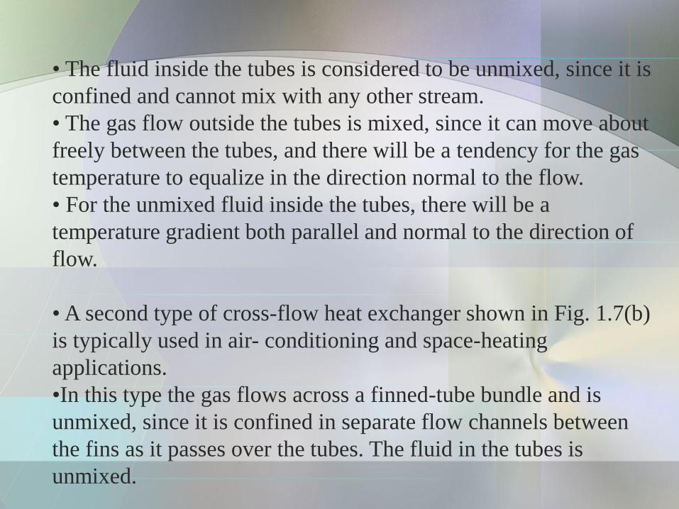
• The fluid inside the tubes is considered to be unmixed, since it is
confined and cannot mix with any other stream.
• The gas flow outside the tubes is mixed, since it can move about
freely between the tubes, and there will be a tendency for the gas
temperature to equalize in the direction normal to the flow.
• For the unmixed fluid inside the tubes, there will be a
temperature gradient both parallel and normal to the direction of
flow.
• A second type of cross-flow heat exchanger shown in Fig. 1.7(b)
is typically used in air- conditioning and space-heating
applications.
•In this type the gas flows across a finned-tube bundle and is
unmixed, since it is confined in separate flow channels between
the fins as it passes over the tubes. The fluid in the tubes is
unmixed.
Log Mean Temperature Difference (LMTD)
Correlation Factors
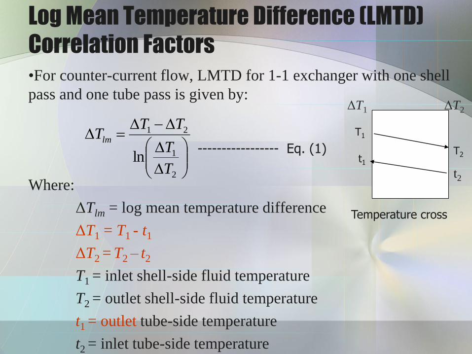
•For counter-current flow, LMTD for 1-1 exchanger with one shell
pass and one tube pass is given by:
Where:
ΔTlm = log mean temperature difference
ΔT1 = T1 - t1
ΔT2 = T2 – t2
T1 = inlet shell-side fluid temperature
T2 = outlet shell-side fluid temperature
t1 = outlet tube-side temperature
t2 = inlet tube-side temperature
T1
t1 T2
t2
Temperature cross
----------------- Eq. (1)
ΔT1 ΔT2
2
1
21
lnT
T
TTTlm
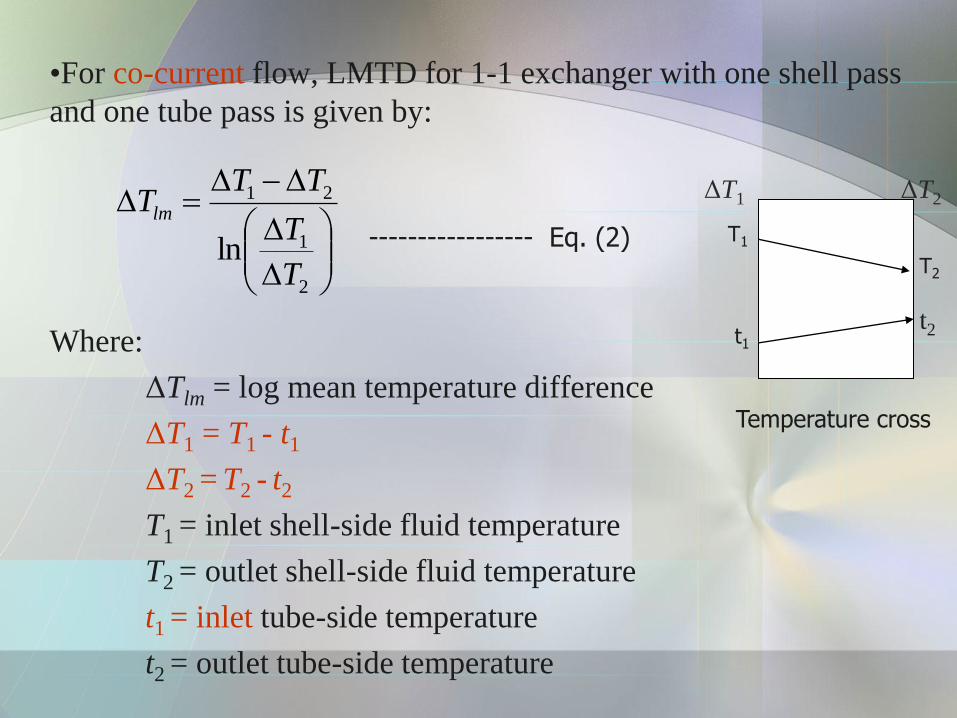
•For co-current flow, LMTD for 1-1 exchanger with one shell pass
and one tube pass is given by:
Where:
ΔTlm = log mean temperature difference
ΔT1 = T1 - t1
ΔT2 = T2 - t2
T1 = inlet shell-side fluid temperature
T2 = outlet shell-side fluid temperature
t1 = inlet tube-side temperature
t2 = outlet tube-side temperature
T1 t1
T2
t2
Temperature cross
----------------- Eq. (2)
2
1
21
lnT
T
TTTlm
ΔT1 ΔT2
Example 1
Water at a rate of 68kg/min is heated from 35 to 75 °C by
an oil having a specific heat of 1.9 kJ/kg.°C. The fluids
are used in a counterflow double-pipe heat exchanger, and
the oil enters the exchangers at 110 ° and leaves at 75 °.
The overall heat-transfer coefficient is 320 W/m2.C.
Calculate the heat exchanger area.

Correction of LMTD in Multipass
Exchanger
• Multipass exchangers have more tube passes than shell passes.
• The LMTD as given in Eq (1 & 2) does not apply in this case
and it is customary to define a correction factor, FT.
• The relationship between LMTD and FT is define as below:
Where is define as the correct mean temperature drop.
• The general equation for heat transfer across surface of an
exchanger is:
lmTm TFT
mT
moomii TAUTAUq
---------------- Eq. (3)
----------------- Eq. (4)
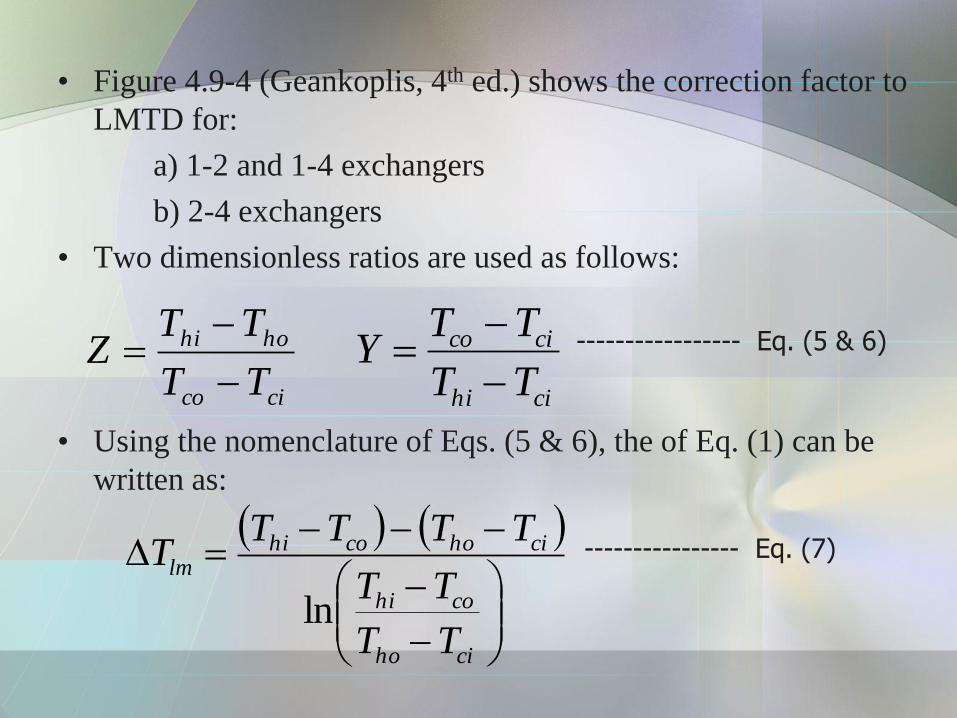
• Figure 4.9-4 (Geankoplis, 4th ed.) shows the correction factor to
LMTD for:
a) 1-2 and 1-4 exchangers
b) 2-4 exchangers
• Two dimensionless ratios are used as follows:
• Using the nomenclature of Eqs. (5 & 6), the of Eq. (1) can be
written as:
cico
hohi
TT
TTZ
cihi
cico
TT
TTY
ciho
cohi
cihocohilm
TT
TT
TTTTT
ln
----------------- Eq. (5 & 6)
---------------- Eq. (7)

Figure 4.9-4(a) Correction factor to LMTD for 1-2 and 1-4 exchangers (Geankoplis, 4th ed.)
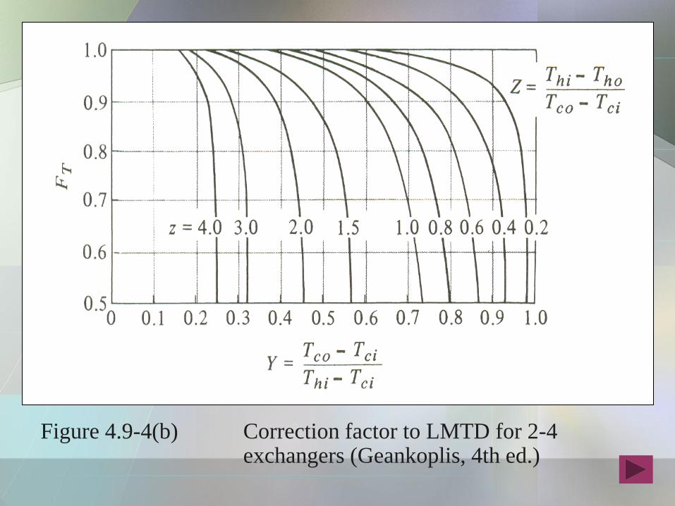
Figure 4.9-4(b) Correction factor to LMTD for 2-4 exchangers (Geankoplis, 4th ed.)
Example 2 Temperature Correction Factor for a Heat
Exchanger
A 1-2 heat exchanger containing one shell pass and two tube passes
heats 2.52 kg/s of water from 21.1 to 54.4 0C by using hot water
under pressure entering at 115.6 and leaving at 48.9 0C. The outside
surface area of the tubes in the exchanger is Ao = 9.30 m2.
a) Calculate the mean temperature different ΔTm in the exchanger
and the overall heat transfer coefficient Uo.
b) For the same temperatures but using a 2-4 exchanger, what would
be the ΔTm?
Solution:
The temperatures are as follows:
Thi = 115.6 0C Tho = 48.9 0C Tci = 21.2 0C
Tco = 54.4 0C
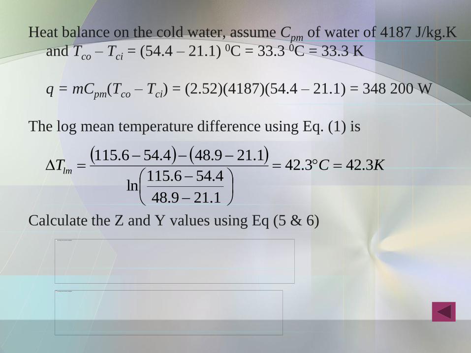
Heat balance on the cold water, assume Cpm of water of 4187 J/kg.K
and Tco – Tci = (54.4 – 21.1) 0C = 33.3 0C = 33.3 K
q = mCpm(Tco – Tci) = (2.52)(4187)(54.4 – 21.1) = 348 200 W
The log mean temperature difference using Eq. (1) is
Calculate the Z and Y values using Eq (5 & 6)
KCTlm 3.423.42
1.219.48
4.546.115ln
1.219.484.546.115
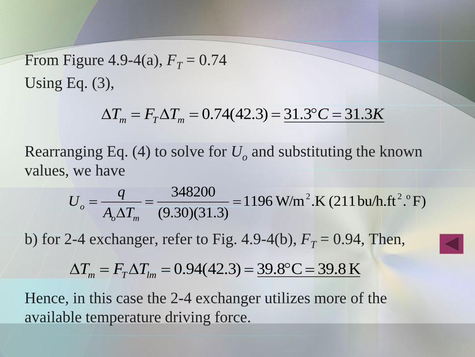
From Figure 4.9-4(a), FT = 0.74
Using Eq. (3),
Rearranging Eq. (4) to solve for Uo and substituting the known
values, we have
b) for 2-4 exchanger, refer to Fig. 4.9-4(b), FT = 0.94, Then,
Hence, in this case the 2-4 exchanger utilizes more of the
available temperature driving force.
KCTFT mTm 3.313.31)3.42(74.0
F).bu/h.ft (211.K W/m1196)3.31)(30.9(
348200 o22
mo
oTA
qU
K 8.39C8.39)3.42(94.0 lmTm TFT
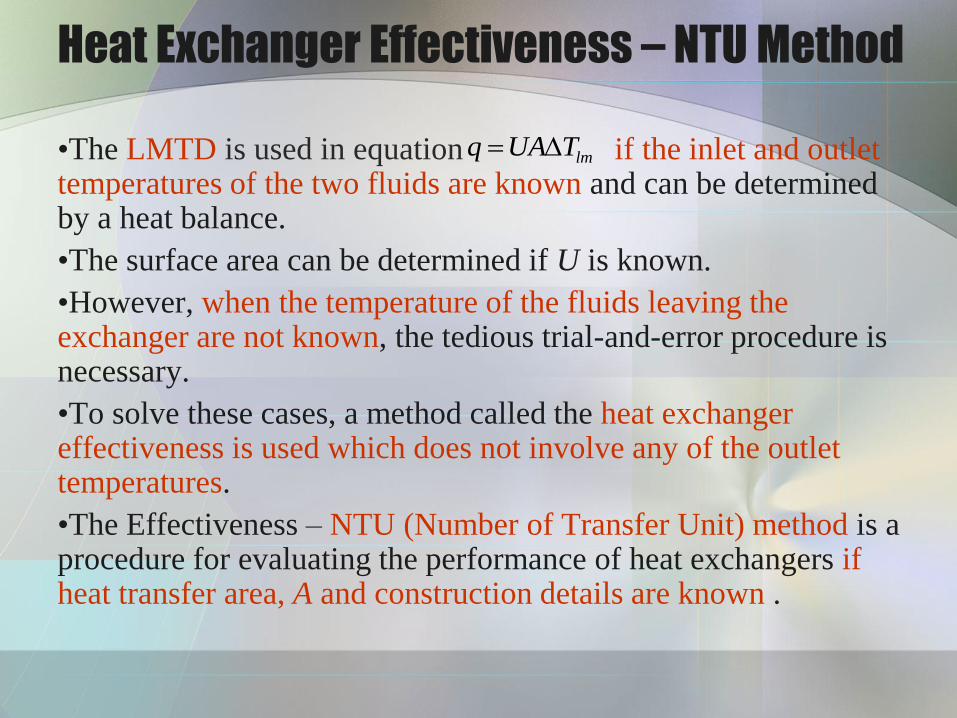
Heat Exchanger Effectiveness – NTU Method
•The LMTD is used in equation if the inlet and outlet temperatures of the two fluids are known and can be determined by a heat balance.
•The surface area can be determined if U is known.
•However, when the temperature of the fluids leaving the exchanger are not known, the tedious trial-and-error procedure is necessary.
•To solve these cases, a method called the heat exchanger effectiveness is used which does not involve any of the outlet temperatures.
•The Effectiveness – NTU (Number of Transfer Unit) method is a procedure for evaluating the performance of heat exchangers if heat transfer area, A and construction details are known .
lmTUAq

•Heat balance for the cold (C ) and hot (H ) fluids is:
•Calling
, then CH > CC
•Designate CC as Cmin or minimum heat capacity.
•If there is an infinite area available for heat transfer, TCo = THi , the effectiveness ε is
•If the hot fluid is the minimum fluid, THo = TCi , and
)(
)(
)(
)(
min
max
CiHi
HoHi
CiHiC
HoHiH
TTC
TTC
TTC
TTC
)(
)(
)(
)(
min
max
CiHi
CiCo
CiHiH
CiCoC
TTC
TTC
TTC
TTC
)()()()( CoCiCpHoHiHp TTmCTTmCq ----------- Eq. (8)
CCp
HHp
CmC
CmC
)(
)(
----------- Eq. (10)
----------- Eq. (9)

• In both equations the denominators are the same and the
numerator gives the actual heat transfer:
• Note that Eq. (11) uses only inlet temperatures.
• For the case of a single-pass, counterflow exchanger, combining
Eqs (9 & 10):
• We consider first the case when the cold fluid is the minimum
fluid. Using the present nomenclature,
)( min CiHi TTCq
----------- Eq. (13)
----------- Eq. (12)
----------- Eq. (11)
)(
)(
)(
)(
minmin CiHi
CiCoC
CiHi
HoHiH
TTC
TTC
TTC
TTC
CoHi
CiHo
CoHiCiHoCiCoC
TT
TT
TTTTUATTCq
ln

•Combining Eq. (8) with the left side of Eq. (12) and solving for
THi.
•Subtracting TCo from both sides,
•From Eq. (8) for Cmin = CC and Cmax = CH ,
•This can be rearranged to give the following:
)(11
)(1
CiCoCiCoCoCiCoHi TTTTTTTT
)(1
CiCoCiHi TTTT
----------- Eq. (14)
----------- Eq. (16)
----------- Eq. (15)
----------- Eq. (17)
)(max
minCiCoHiHo TT
C
CTT
)(max
minCiCoCiHiCiHo TT
C
CTTTT

•Substituting Eq. (14) into Eq. (17),
•Finally, substituting Eq. (15) and Eq. (18) into Eq. (13), rearranging, taking the antilog of both sides, and solving for ε,
•We define NTU as the number of transfer unit as follows:
•The same results would have been obtained if CH = Cmin
)(1
max
minCiCoCiCoCiHo TT
C
CTTTT
----------- Eq. (19)
----------- Eq. (18)
----------- Eq. (20)
max
min
minmax
min
max
min
min
1exp1
1exp1
C
C
C
UA
C
C
C
C
C
UA
UA
NTUminC
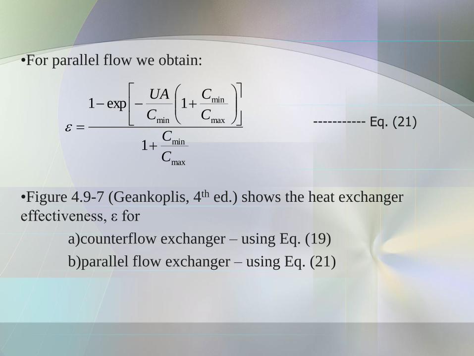
•For parallel flow we obtain:
•Figure 4.9-7 (Geankoplis, 4th ed.) shows the heat exchanger
effectiveness, ε for
a)counterflow exchanger – using Eq. (19)
b)parallel flow exchanger – using Eq. (21)
max
min
max
min
min
1
1exp1
C
C
C
C
C
UA
----------- Eq. (21)

Figure 4.9-7 Heat exchanger effectiveness, ε:
a)counterflow exchanger; b)parallel flow exchanger
(Geankoplis, 4th ed.)
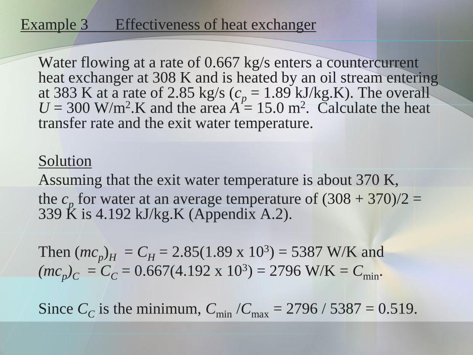
Example 3 Effectiveness of heat exchanger
Water flowing at a rate of 0.667 kg/s enters a countercurrent heat exchanger at 308 K and is heated by an oil stream entering at 383 K at a rate of 2.85 kg/s (cp = 1.89 kJ/kg.K). The overall U = 300 W/m2.K and the area A = 15.0 m2. Calculate the heat transfer rate and the exit water temperature.
Solution
Assuming that the exit water temperature is about 370 K,
the cp for water at an average temperature of (308 + 370)/2 = 339 K is 4.192 kJ/kg.K (Appendix A.2).
Then (mcp)H = CH = 2.85(1.89 x 10³) = 5387 W/K and
(mcp)C = CC = 0.667(4.192 x 10³) = 2796 W/K = Cmin.
Since CC is the minimum, Cmin /Cmax = 2796 / 5387 = 0.519.
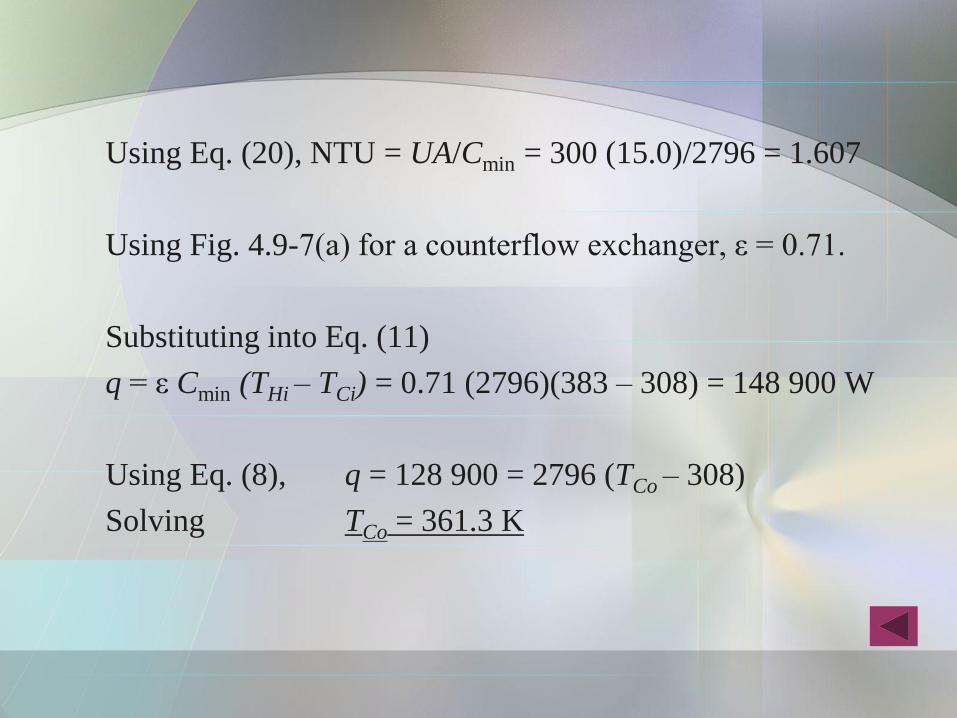
Using Eq. (20), NTU = UA/Cmin = 300 (15.0)/2796 = 1.607
Using Fig. 4.9-7(a) for a counterflow exchanger, ε = 0.71.
Substituting into Eq. (11)
q = ε Cmin (THi – TCi) = 0.71 (2796)(383 – 308) = 148 900 W
Using Eq. (8), q = 128 900 = 2796 (TCo – 308)
Solving TCo = 361.3 K
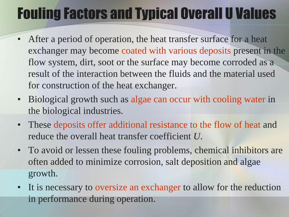
Fouling Factors and Typical Overall U Values
• After a period of operation, the heat transfer surface for a heat
exchanger may become coated with various deposits present in the
flow system, dirt, soot or the surface may become corroded as a
result of the interaction between the fluids and the material used
for construction of the heat exchanger.
• Biological growth such as algae can occur with cooling water in
the biological industries.
• These deposits offer additional resistance to the flow of heat and
reduce the overall heat transfer coefficient U.
• To avoid or lessen these fouling problems, chemical inhibitors are
often added to minimize corrosion, salt deposition and algae
growth.
• It is necessary to oversize an exchanger to allow for the reduction
in performance during operation.
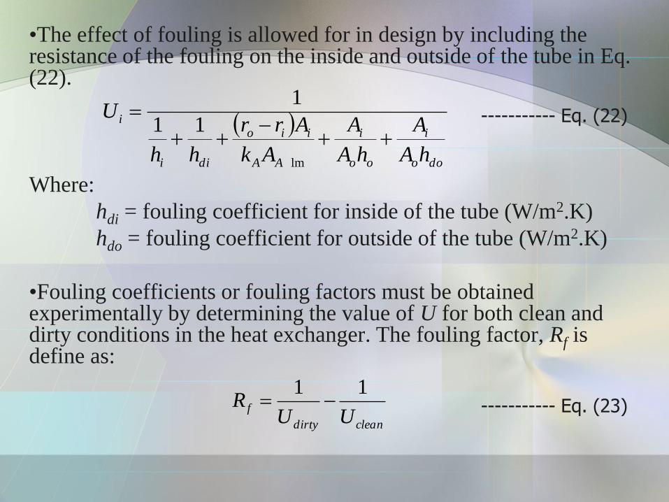
•The effect of fouling is allowed for in design by including the resistance of the fouling on the inside and outside of the tube in Eq. (22).
Where:
hdi = fouling coefficient for inside of the tube (W/m2.K)
hdo = fouling coefficient for outside of the tube (W/m2.K)
•Fouling coefficients or fouling factors must be obtained experimentally by determining the value of U for both clean and dirty conditions in the heat exchanger. The fouling factor, Rf is define as:
doo
i
oo
i
AA
iio
dii
i
hA
A
hA
A
Ak
Arr
hh
U
lm
11
1----------- Eq. (22)
cleandirty
fUU
R11
----------- Eq. (23)

•Typical Fouling Coefficients is shown in Table 1 and the typical
values of overall heat transfer coefficients are given in Table 2.
Table 1 Typical Fouling Coefficients
hd
(W/m2.K)
hd
(btu/h.ft2.0F)
Distilled and seawater
City water
Muddy water
Gases
Vaporizing liquids
Vegetable and gas oils
11350
5680
1990-2840
2840
2840
1990
2000
1000
350-500
500
500
350

Table 2 Typical Values of Overall Heat Transfer
Coefficient in Shell and Tube Exchanger
U
(W/m2.K)
U
(btu/h.ft2.0F)
Water to water
Water to brine
Water to organic liquids
Water to condensing steam
Water to gasoline
Water to gas oil
Water to vegetable oil
Gas oil to gas oil
Steam to boiling water
Water to air (finned tube)
Light organics to light organics
Heavy organics to heavy organics
1140 – 1700
570 – 1140
570 – 1140
1420 – 2270
340 – 570
140 – 340
110 – 285
110 – 285
1420 – 2270
110 – 230
230 – 425
55 - 230
200 – 300
100 – 200
100 – 200
250 – 400
60 – 100
25 – 60
20 – 50
20 – 50
250 – 400
20 – 40
40 – 75
10 – 40

Design of a Shell and Tube Exchangers
Example 4
Water at the rate of 3.783 kg/s is heated from 37.78 to 54.44 °C in a shell-tube heat exchanger. On the shell side one pass is used with water as the heating fluid, 1.892 kg/s, entering the heat exchanger at 93.33 °C. The overall heat transfer coefficient is 1419 W/m2.°C, and the average water velocity in the 1.905-cm diameter tubes is 0.366 m/s. Because of the space limitations, the tube length must not longer than 2.438 m. Calculate the number of tube passes, the number of tubes per pass, and the length of the tubes, consistent with restriction.
Use a split-ring floating head type. The bundle diametrical clearance = 68 mm
Hence, shell diameter, Ds = 826 + 68 = 894 mm.