Embed Size (px)
Citation preview
PUBLIC NOTICE
DRAFT MISSOURI STATE OPERATING PERMIT DATE: January 5, 2018 In accordance with the state Clean Water Law, Chapter 644, RSMo, Missouri Clean Water Commission regulation 10 CSR 20-6.010, and the Federal Clean Water Act, the applicants listed herein have applied for authorization to either discharge to waters of the state, or to operate a no-discharge wastewater treatment facility. The proposed permits for these operations are consistent with applicable water quality standards, effluent standards and/or treatment requirements or suitable timetables to meet these requirements (see 10 CSR 20-7.015 and 7.031). All permits will be issued for a period of five years unless noted otherwise in the Public Notice for that discharge. On the basis of preliminary staff review and the application of applicable standards and regulations, the Missouri Department of Natural Resources, as administrative agent for the Missouri Clean Water Commission, proposes to issue a permit(s) subject to certain effluent limitations, schedules, and special conditions. The proposed determinations are tentative pending public comment. Persons wishing to comment on the proposed permit conditions are invited to submit them in writing to: Missouri Department of Natural Resources, Water Protection Program, P.O. Box 176, Jefferson City, MO 65102, ATTN: NPDES Operating Permits /Permit Comments. Please include the permit number in all comment letters. Comments should be confined to the issues relating to the proposed action and permit(s) and the effect on water quality. The Department may not consider as relevant comments or objections to a permit based on issues outside the authority of the Missouri Clean Water Commission, (see Curdt v. Mo. Clean Water Commission, 586 S.W.2d 58 Mo. App. 1979). All comments must be received or postmarked by 5:00 p.m. on February 5, 2018. The Department will consider all written comments, including e-mails, faxes and letters, in the formulation of all final determinations regarding the applications. Email comments will be accepted at the following address: [email protected]. If response to this notice indicates significant public interest, a public meeting or hearing may be held after due notice for the purpose of receiving public comment on the proposed permit or determination. Public hearings and/or issuance of the permit will be conducted or processed according to 10 CSR 20-6.020. Copies of all draft permits and other information including copies of applicable regulations are available for inspection and copying at the Department’s Website: http://www.dnr.mo.gov/env/wpp/permits/permit-pn.htm, or at the Department of Natural Resources, Water Protection Program, P.O. Box 176, Jefferson City, MO 65102, between the hours of 8:00 a.m. and 5:00 p.m., Monday through Friday.
MO-0000043 Page 1 of 16
STATE OF MISSOURI
DEPARTMENT OF NATURAL RESOURCES
MISSOURI CLEAN WATER COMMISSION
MISSOURI STATE OPERATING PERMIT
In compliance with the Missouri Clean Water Law, (Chapter 644 R.S. Mo. as amended, hereinafter, the Law), and the Federal Water Pollution Control Act (Public Law 92-500, 92nd Congress) as amended, Permit No. MO-0000043 Owner: Ameren Address: P.O. Box 66149, MC-602, St. Louis, MO 63166-6149 Continuing Authority: Same as above Address: Same as above Facility Name: Ameren Missouri- Rush Island Energy Center Facility Address: 100 Big Hollow Road, Festus, MO 63028 Legal Description: See Page 2 UTM Coordinates: See Page 2 Receiving Stream: See Page 2 First Classified Stream and ID: See Page 2 USGS Basin & Sub-watershed No.: See Page 2 is authorized to discharge from the facility described herein, in accordance with the effluent limitations and monitoring requirements as set forth herein: FACILITY DESCRIPTION See Page 2 for facility description. Ameren Missouri- Rush Island Energy Center is a steam electrical power generation primarily engaged in the generation of electricity for distribution and sale. The facility commenced operations in 1976. The facility’s two coal-fired boilers produce steam for the generation of approximately 1250MWe. This facility has eight (8) designated permitted features. This permit authorizes only wastewater and stormwater discharges under the Missouri Clean Water Law and the National Pollutant Discharge Elimination System; it does not apply to other regulated areas. This permit may be appealed in accordance with Sections 640.013, 621.250, and 644.051.6 of the Law. Effective Date Edward B Galbraith, Director, Division of Environmental Quality Expiration Date Chris Wieberg, Director, Water Protection Program
MO-0000043 Page 2 of 16
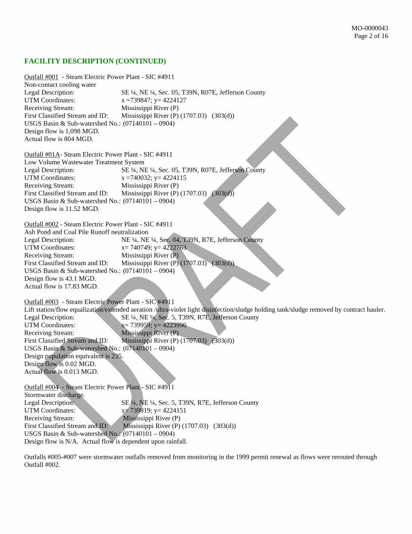
FACILITY DESCRIPTION (CONTINUED) Outfall #001 - Steam Electric Power Plant - SIC #4911 Non-contact cooling water Legal Description: SE ¼, NE ¼, Sec. 05, T39N, R07E, Jefferson County UTM Coordinates: x =739847; y= 4224127 Receiving Stream: Mississippi River (P) First Classified Stream and ID: Mississippi River (P) (1707.03) (303(d)) USGS Basin & Sub-watershed No.: (07140101 – 0904) Design flow is 1,098 MGD. Actual flow is 804 MGD. Outfall #01A- Steam Electric Power Plant - SIC #4911 Low Volume Wastewater Treatment System Legal Description: SE ¼, NE ¼, Sec. 05, T39N, R07E, Jefferson County UTM Coordinates: x =740032; y= 4224115 Receiving Stream: Mississippi River (P) First Classified Stream and ID: Mississippi River (P) (1707.03) (303(d)) USGS Basin & Sub-watershed No.: (07140101 – 0904) Design flow is 11.52 MGD. Outfall #002 - Steam Electric Power Plant - SIC #4911 Ash Pond and Coal Pile Runoff neutralization Legal Description: NE ¼, NE ¼, Sec. 04, T39N, R7E, Jefferson County UTM Coordinates: x= 740749; y= 4222763 Receiving Stream: Mississippi River (P) First Classified Stream and ID: Mississippi River (P) (1707.03) (303(d)) USGS Basin & Sub-watershed No.: (07140101 – 0904) Design flow is 43.1 MGD. Actual flow is 17.83 MGD. Outfall #003 - Steam Electric Power Plant - SIC #4911 Lift station/flow equalization/extended aeration /ultra-violet light disinfection/sludge holding tank/sludge removed by contract hauler. Legal Description: SE ¼, NE ¼, Sec. 5, T39N, R7E, Jefferson County UTM Coordinates: x= 739959; y= 4223996 Receiving Stream: Mississippi River (P) First Classified Stream and ID: Mississippi River (P) (1707.03) (303(d)) USGS Basin & Sub-watershed No.: (07140101 – 0904) Design population equivalent is 235. Design flow is 0.02 MGD. Actual flow is 0.013 MGD. Outfall #004 - Steam Electric Power Plant - SIC #4911 Stormwater discharge. Legal Description: SE ¼, NE ¼, Sec. 5, T39N, R7E, Jefferson County UTM Coordinates: x= 739819; y= 4224151 Receiving Stream: Mississippi River (P) First Classified Stream and ID: Mississippi River (P) (1707.03) (303(d)) USGS Basin & Sub-watershed No.: (07140101 – 0904) Design flow is N/A. Actual flow is dependent upon rainfall. Outfalls #005-#007 were stormwater outfalls removed from monitoring in the 1999 permit renewal as flows were rerouted through Outfall #002.
MO-0000043 Page 3 of 16
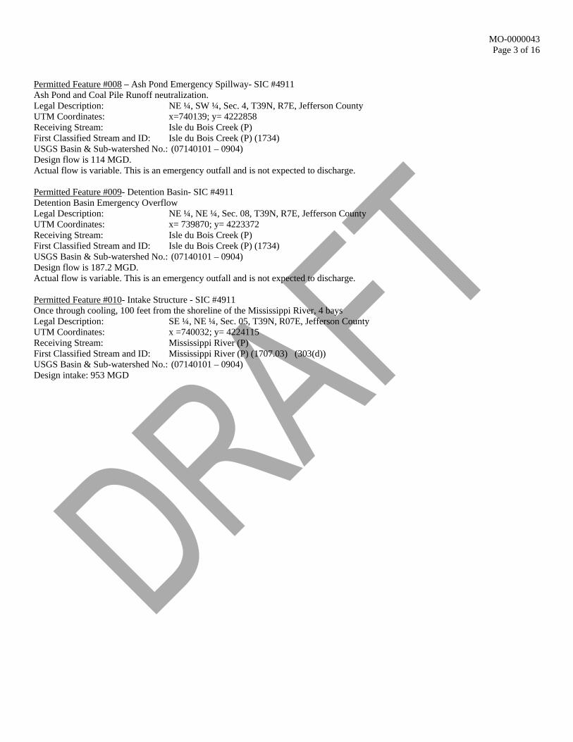
Permitted Feature #008 – Ash Pond Emergency Spillway- SIC #4911 Ash Pond and Coal Pile Runoff neutralization. Legal Description: NE ¼, SW ¼, Sec. 4, T39N, R7E, Jefferson County UTM Coordinates: x=740139; y= 4222858 Receiving Stream: Isle du Bois Creek (P) First Classified Stream and ID: Isle du Bois Creek (P) (1734) USGS Basin & Sub-watershed No.: (07140101 – 0904) Design flow is 114 MGD. Actual flow is variable. This is an emergency outfall and is not expected to discharge. Permitted Feature #009- Detention Basin- SIC #4911 Detention Basin Emergency Overflow Legal Description: NE ¼, NE ¼, Sec. 08, T39N, R7E, Jefferson County UTM Coordinates: x= 739870; y= 4223372 Receiving Stream: Isle du Bois Creek (P) First Classified Stream and ID: Isle du Bois Creek (P) (1734) USGS Basin & Sub-watershed No.: (07140101 – 0904) Design flow is 187.2 MGD. Actual flow is variable. This is an emergency outfall and is not expected to discharge. Permitted Feature #010- Intake Structure - SIC #4911 Once through cooling, 100 feet from the shoreline of the Mississippi River, 4 bays Legal Description: SE ¼, NE ¼, Sec. 05, T39N, R07E, Jefferson County UTM Coordinates: x =740032; y= 4224115 Receiving Stream: Mississippi River (P) First Classified Stream and ID: Mississippi River (P) (1707.03) (303(d)) USGS Basin & Sub-watershed No.: (07140101 – 0904) Design intake: 953 MGD
MO-0000043 Page 4 of 16
A. EFFLUENT LIMITATIONS AND MONITORING REQUIREMENTS
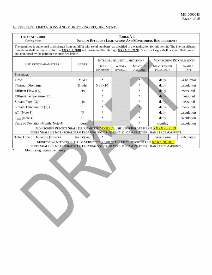
OUTFALL #001 Cooling Water
TABLE A-1 INTERIM EFFLUENT LIMITATIONS AND MONITORING REQUIREMENTS
The permittee is authorized to discharge from outfall(s) with serial number(s) as specified in the application for this permit. The interim effluent limitations shall become effective on XXXX 1, 2018 and remain in effect through XXXX 31, 2020. Such discharges shall be controlled, limited and monitored by the permittee as specified below:
EFFLUENT PARAMETERS UNITS INTERIM EFFLUENT LIMITATIONS MONITORING REQUIREMENTS DAILY
MAXIMUM WEEKLY AVERAGE
MONTHLY AVERAGE
MEASUREMENT FREQUENCY
SAMPLE TYPE
PHYSICAL Flow MGD * * daily 24 hr. total Thermal Discharge Btu/hr 5.81 x10⁹ * daily calculation Effluent Flow (Qe) cfs * * daily measured Effluent Temperature (Te) °F * * daily measured Stream Flow (Qs) cfs * * daily measured Stream Temperature (Ts) °F * * daily measured ΔT (Note 3) °F * * daily calculation Temz (Note 4) °F * * daily calculation Time of Deviation-Month (Note 4) hours * monthly calculation
MONITORING REPORTS SHALL BE SUBMITTED MONTHLY; THE FIRST REPORT IS DUE XXXX 28, 2019. THERE SHALL BE NO DISCHARGE OF FLOATING SOLIDS OR VISIBLE FOAM IN OTHER THAN TRACE AMOUNTS.
Total Time of Deviation (Note 4) hours/year * yearly sum calculation MONITORING REPORTS SHALL BE SUBMITTED YEARLY; THE FIRST REPORT IS DUE XXXX 28, 2019.
THERE SHALL BE NO DISCHARGE OF FLOATING SOLIDS OR VISIBLE FOAM IN OTHER THAN TRACE AMOUNTS. * Monitoring requirement only.
MO-0000043 Page 5 of 16
A. EFFLUENT LIMITATIONS AND MONITORING REQUIREMENTS (CONTINUED)
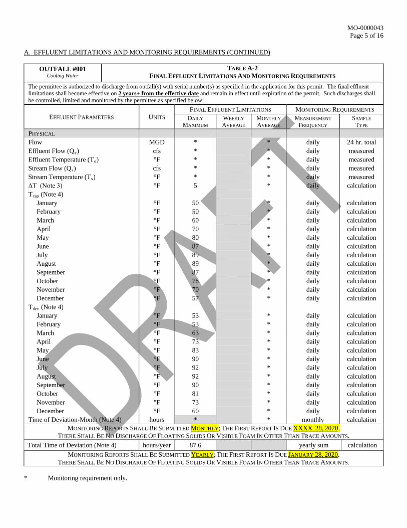
OUTFALL #001 Cooling Water
TABLE A-2 FINAL EFFLUENT LIMITATIONS AND MONITORING REQUIREMENTS
The permittee is authorized to discharge from outfall(s) with serial number(s) as specified in the application for this permit. The final effluent limitations shall become effective on 2 years+ from the effective date and remain in effect until expiration of the permit. Such discharges shall be controlled, limited and monitored by the permittee as specified below:
EFFLUENT PARAMETERS UNITS FINAL EFFLUENT LIMITATIONS MONITORING REQUIREMENTS
DAILY MAXIMUM
WEEKLY AVERAGE
MONTHLY AVERAGE
MEASUREMENT FREQUENCY
SAMPLE TYPE
PHYSICAL Flow MGD * * daily 24 hr. total Effluent Flow (Qe) cfs * * daily measured Effluent Temperature (Te) °F * * daily measured Stream Flow (Qs) cfs * * daily measured Stream Temperature (Ts) °F * * daily measured ΔT (Note 3) °F 5 * daily calculation Tcap (Note 4) January °F 50 * daily calculation February °F 50 * daily calculation March °F 60 * daily calculation April °F 70 * daily calculation May °F 80 * daily calculation June °F 87 * daily calculation July °F 89 * daily calculation August °F 89 * daily calculation September °F 87 * daily calculation October °F 78 * daily calculation November °F 70 * daily calculation December °F 57 * daily calculation Tdev (Note 4) January °F 53 * daily calculation February °F 53 * daily calculation March °F 63 * daily calculation April °F 73 * daily calculation May °F 83 * daily calculation June °F 90 * daily calculation July °F 92 * daily calculation August °F 92 * daily calculation September °F 90 * daily calculation October °F 81 * daily calculation November °F 73 * daily calculation December °F 60 * daily calculation Time of Deviation-Month (Note 4) hours * * monthly calculation
MONITORING REPORTS SHALL BE SUBMITTED MONTHLY; THE FIRST REPORT IS DUE XXXX 28, 2020. THERE SHALL BE NO DISCHARGE OF FLOATING SOLIDS OR VISIBLE FOAM IN OTHER THAN TRACE AMOUNTS.
Total Time of Deviation (Note 4) hours/year 87.6 yearly sum calculation MONITORING REPORTS SHALL BE SUBMITTED YEARLY; THE FIRST REPORT IS DUE JANUARY 28, 2020.
THERE SHALL BE NO DISCHARGE OF FLOATING SOLIDS OR VISIBLE FOAM IN OTHER THAN TRACE AMOUNTS. * Monitoring requirement only.
MO-0000043 Page 6 of 16
A. EFFLUENT LIMITATIONS AND MONITORING REQUIREMENTS (CONTINUED)
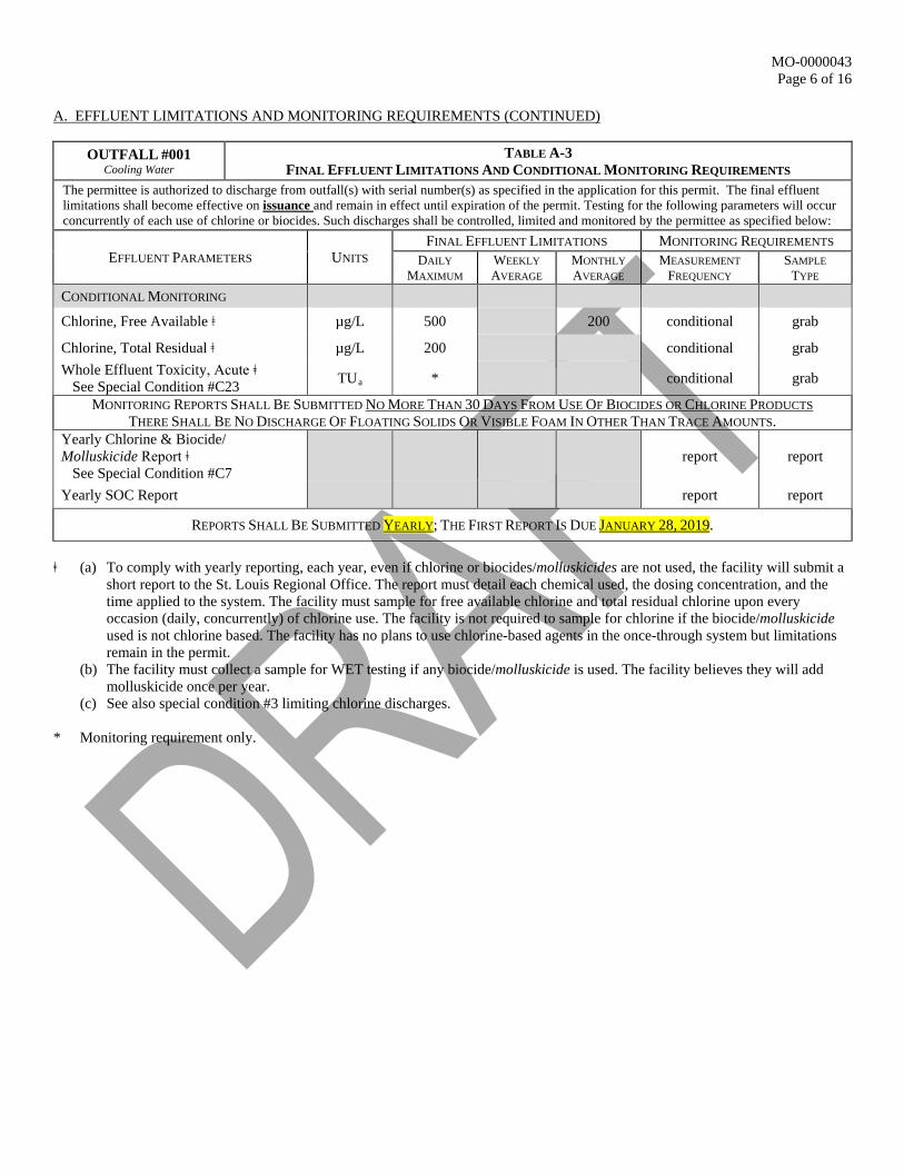
OUTFALL #001 Cooling Water
TABLE A-3 FINAL EFFLUENT LIMITATIONS AND CONDITIONAL MONITORING REQUIREMENTS
The permittee is authorized to discharge from outfall(s) with serial number(s) as specified in the application for this permit. The final effluent limitations shall become effective on issuance and remain in effect until expiration of the permit. Testing for the following parameters will occur concurrently of each use of chlorine or biocides. Such discharges shall be controlled, limited and monitored by the permittee as specified below:
EFFLUENT PARAMETERS UNITS FINAL EFFLUENT LIMITATIONS MONITORING REQUIREMENTS
DAILY MAXIMUM
WEEKLY AVERAGE
MONTHLY AVERAGE
MEASUREMENT FREQUENCY
SAMPLE TYPE
CONDITIONAL MONITORING
Chlorine, Free Available ǂ µg/L 500 200 conditional grab
Chlorine, Total Residual ǂ µg/L 200 conditional grab Whole Effluent Toxicity, Acute ǂ See Special Condition #C23 TUa * conditional grab
MONITORING REPORTS SHALL BE SUBMITTED NO MORE THAN 30 DAYS FROM USE OF BIOCIDES OR CHLORINE PRODUCTS THERE SHALL BE NO DISCHARGE OF FLOATING SOLIDS OR VISIBLE FOAM IN OTHER THAN TRACE AMOUNTS.
Yearly Chlorine & Biocide/ Molluskicide Report ǂ See Special Condition #C7
report report
Yearly SOC Report report report
REPORTS SHALL BE SUBMITTED YEARLY; THE FIRST REPORT IS DUE JANUARY 28, 2019.
ǂ (a) To comply with yearly reporting, each year, even if chlorine or biocides/molluskicides are not used, the facility will submit a
short report to the St. Louis Regional Office. The report must detail each chemical used, the dosing concentration, and the time applied to the system. The facility must sample for free available chlorine and total residual chlorine upon every occasion (daily, concurrently) of chlorine use. The facility is not required to sample for chlorine if the biocide/molluskicide used is not chlorine based. The facility has no plans to use chlorine-based agents in the once-through system but limitations remain in the permit.
(b) The facility must collect a sample for WET testing if any biocide/molluskicide is used. The facility believes they will add molluskicide once per year.
(c) See also special condition #3 limiting chlorine discharges. * Monitoring requirement only.
MO-0000043 Page 7 of 16
A. EFFLUENT LIMITATIONS AND MONITORING REQUIREMENTS (CONTINUED)
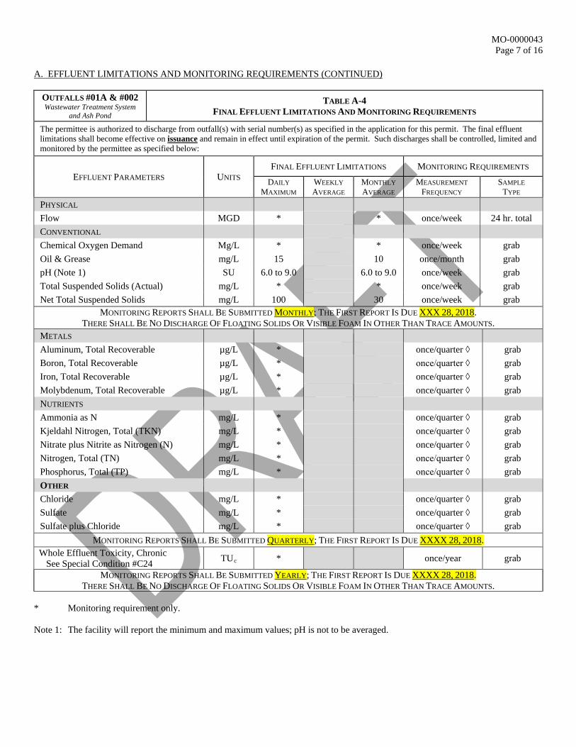
OUTFALLS #01A & #002 Wastewater Treatment System
and Ash Pond
TABLE A-4 FINAL EFFLUENT LIMITATIONS AND MONITORING REQUIREMENTS
The permittee is authorized to discharge from outfall(s) with serial number(s) as specified in the application for this permit. The final effluent limitations shall become effective on issuance and remain in effect until expiration of the permit. Such discharges shall be controlled, limited and monitored by the permittee as specified below:
EFFLUENT PARAMETERS UNITS FINAL EFFLUENT LIMITATIONS MONITORING REQUIREMENTS
DAILY MAXIMUM
WEEKLY AVERAGE
MONTHLY AVERAGE
MEASUREMENT FREQUENCY
SAMPLE TYPE
PHYSICAL Flow MGD * * once/week 24 hr. total CONVENTIONAL Chemical Oxygen Demand Mg/L * * once/week grab Oil & Grease mg/L 15 10 once/month grab pH (Note 1) SU 6.0 to 9.0 6.0 to 9.0 once/week grab Total Suspended Solids (Actual) mg/L * * once/week grab Net Total Suspended Solids mg/L 100 30 once/week grab
MONITORING REPORTS SHALL BE SUBMITTED MONTHLY; THE FIRST REPORT IS DUE XXX 28, 2018. THERE SHALL BE NO DISCHARGE OF FLOATING SOLIDS OR VISIBLE FOAM IN OTHER THAN TRACE AMOUNTS.
METALS Aluminum, Total Recoverable µg/L * once/quarter ◊ grab Boron, Total Recoverable µg/L * once/quarter ◊ grab Iron, Total Recoverable µg/L * once/quarter ◊ grab Molybdenum, Total Recoverable µg/L * once/quarter ◊ grab NUTRIENTS Ammonia as N mg/L * once/quarter ◊ grab Kjeldahl Nitrogen, Total (TKN) mg/L * once/quarter ◊ grab Nitrate plus Nitrite as Nitrogen (N) mg/L * once/quarter ◊ grab Nitrogen, Total (TN) mg/L * once/quarter ◊ grab Phosphorus, Total (TP) mg/L * once/quarter ◊ grab OTHER Chloride mg/L * once/quarter ◊ grab Sulfate mg/L * once/quarter ◊ grab Sulfate plus Chloride mg/L * once/quarter ◊ grab
MONITORING REPORTS SHALL BE SUBMITTED QUARTERLY; THE FIRST REPORT IS DUE XXXX 28, 2018. Whole Effluent Toxicity, Chronic See Special Condition #C24 TUc * once/year grab
MONITORING REPORTS SHALL BE SUBMITTED YEARLY; THE FIRST REPORT IS DUE XXXX 28, 2018. THERE SHALL BE NO DISCHARGE OF FLOATING SOLIDS OR VISIBLE FOAM IN OTHER THAN TRACE AMOUNTS.
* Monitoring requirement only. Note 1: The facility will report the minimum and maximum values; pH is not to be averaged.
MO-0000043 Page 8 of 16
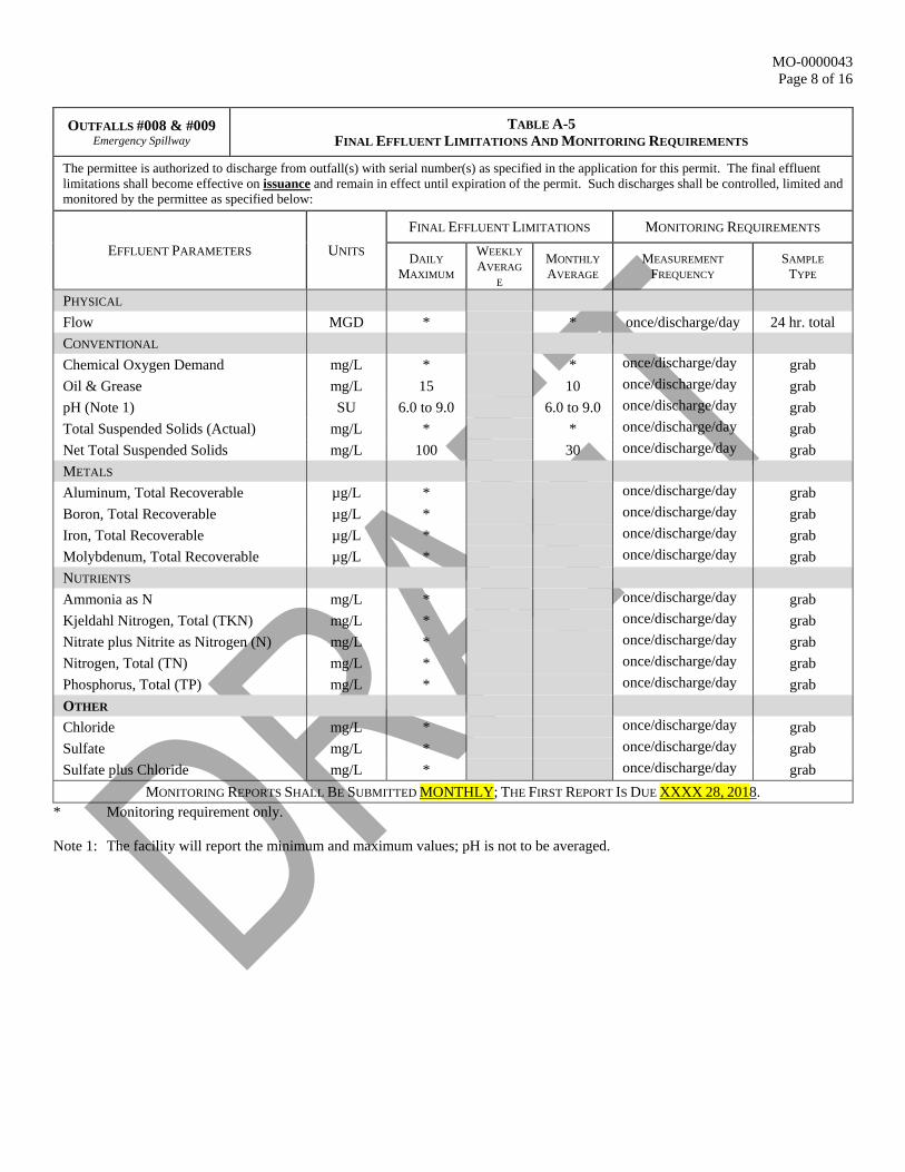
OUTFALLS #008 & #009 Emergency Spillway
TABLE A-5 FINAL EFFLUENT LIMITATIONS AND MONITORING REQUIREMENTS
The permittee is authorized to discharge from outfall(s) with serial number(s) as specified in the application for this permit. The final effluent limitations shall become effective on issuance and remain in effect until expiration of the permit. Such discharges shall be controlled, limited and monitored by the permittee as specified below:
EFFLUENT PARAMETERS UNITS FINAL EFFLUENT LIMITATIONS MONITORING REQUIREMENTS
DAILY MAXIMUM
WEEKLY AVERAG
E
MONTHLY AVERAGE
MEASUREMENT FREQUENCY
SAMPLE TYPE
PHYSICAL Flow MGD * * once/discharge/day 24 hr. total CONVENTIONAL Chemical Oxygen Demand mg/L * * once/discharge/day grab Oil & Grease mg/L 15 10 once/discharge/day grab pH (Note 1) SU 6.0 to 9.0 6.0 to 9.0 once/discharge/day grab Total Suspended Solids (Actual) mg/L * * once/discharge/day grab Net Total Suspended Solids mg/L 100 30 once/discharge/day grab METALS Aluminum, Total Recoverable µg/L * once/discharge/day grab Boron, Total Recoverable µg/L * once/discharge/day grab Iron, Total Recoverable µg/L * once/discharge/day grab Molybdenum, Total Recoverable µg/L * once/discharge/day grab NUTRIENTS Ammonia as N mg/L * once/discharge/day grab Kjeldahl Nitrogen, Total (TKN) mg/L * once/discharge/day grab Nitrate plus Nitrite as Nitrogen (N) mg/L * once/discharge/day grab Nitrogen, Total (TN) mg/L * once/discharge/day grab Phosphorus, Total (TP) mg/L * once/discharge/day grab OTHER Chloride mg/L * once/discharge/day grab Sulfate mg/L * once/discharge/day grab Sulfate plus Chloride mg/L * once/discharge/day grab
MONITORING REPORTS SHALL BE SUBMITTED MONTHLY; THE FIRST REPORT IS DUE XXXX 28, 2018. * Monitoring requirement only. Note 1: The facility will report the minimum and maximum values; pH is not to be averaged.
MO-0000043 Page 9 of 16
A. EFFLUENT LIMITATIONS AND MONITORING REQUIREMENTS (CONTINUED)
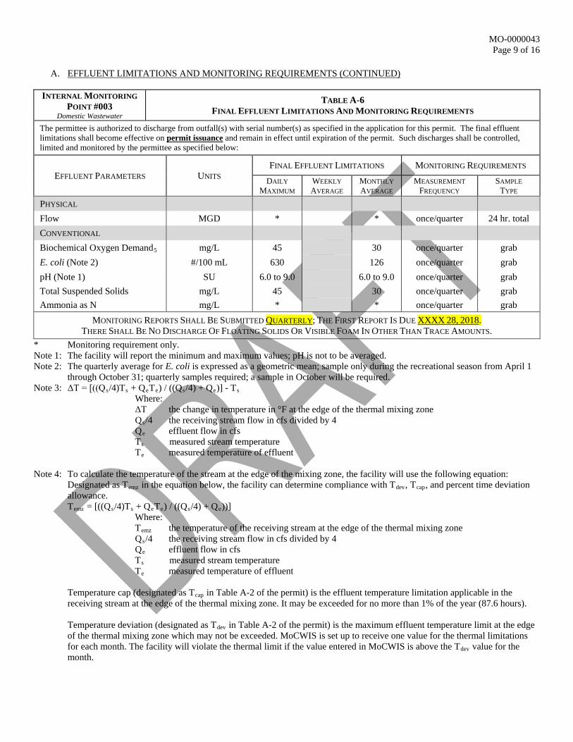
INTERNAL MONITORING
POINT #003 Domestic Wastewater
TABLE A-6 FINAL EFFLUENT LIMITATIONS AND MONITORING REQUIREMENTS
The permittee is authorized to discharge from outfall(s) with serial number(s) as specified in the application for this permit. The final effluent limitations shall become effective on permit issuance and remain in effect until expiration of the permit. Such discharges shall be controlled, limited and monitored by the permittee as specified below:
EFFLUENT PARAMETERS UNITS FINAL EFFLUENT LIMITATIONS MONITORING REQUIREMENTS
DAILY MAXIMUM
WEEKLY AVERAGE
MONTHLY AVERAGE
MEASUREMENT FREQUENCY
SAMPLE TYPE
PHYSICAL Flow MGD * * once/quarter 24 hr. total CONVENTIONAL Biochemical Oxygen Demand5 mg/L 45 30 once/quarter grab E. coli (Note 2) #/100 mL 630 126 once/quarter grab pH (Note 1) SU 6.0 to 9.0 6.0 to 9.0 once/quarter grab Total Suspended Solids mg/L 45 30 once/quarter grab Ammonia as N mg/L * * once/quarter grab
MONITORING REPORTS SHALL BE SUBMITTED QUARTERLY; THE FIRST REPORT IS DUE XXXX 28, 2018. THERE SHALL BE NO DISCHARGE OF FLOATING SOLIDS OR VISIBLE FOAM IN OTHER THAN TRACE AMOUNTS.
* Monitoring requirement only. Note 1: The facility will report the minimum and maximum values; pH is not to be averaged. Note 2: The quarterly average for E. coli is expressed as a geometric mean; sample only during the recreational season from April 1
through October 31; quarterly samples required; a sample in October will be required. Note 3: ΔT = [((Qs/4)Ts + QeTe) / ((Qs/4) + Qe)] - Ts
Where: ΔT the change in temperature in °F at the edge of the thermal mixing zone Qs/4 the receiving stream flow in cfs divided by 4 Qe effluent flow in cfs Ts measured stream temperature Te measured temperature of effluent
Note 4: To calculate the temperature of the stream at the edge of the mixing zone, the facility will use the following equation:
Designated as Temz in the equation below, the facility can determine compliance with Tdev, Tcap, and percent time deviation allowance.
Temz = [((Qs/4)Ts + QeTe) / ((Qs/4) + Qe))] Where: Temz the temperature of the receiving stream at the edge of the thermal mixing zone Qs/4 the receiving stream flow in cfs divided by 4 Qe effluent flow in cfs Ts measured stream temperature Te measured temperature of effluent
Temperature cap (designated as Tcap in Table A-2 of the permit) is the effluent temperature limitation applicable in the receiving stream at the edge of the thermal mixing zone. It may be exceeded for no more than 1% of the year (87.6 hours).
Temperature deviation (designated as Tdev in Table A-2 of the permit) is the maximum effluent temperature limit at the edge of the thermal mixing zone which may not be exceeded. MoCWIS is set up to receive one value for the thermal limitations for each month. The facility will violate the thermal limit if the value entered in MoCWIS is above the Tdev value for the month.
MO-0000043 Page 10 of 16
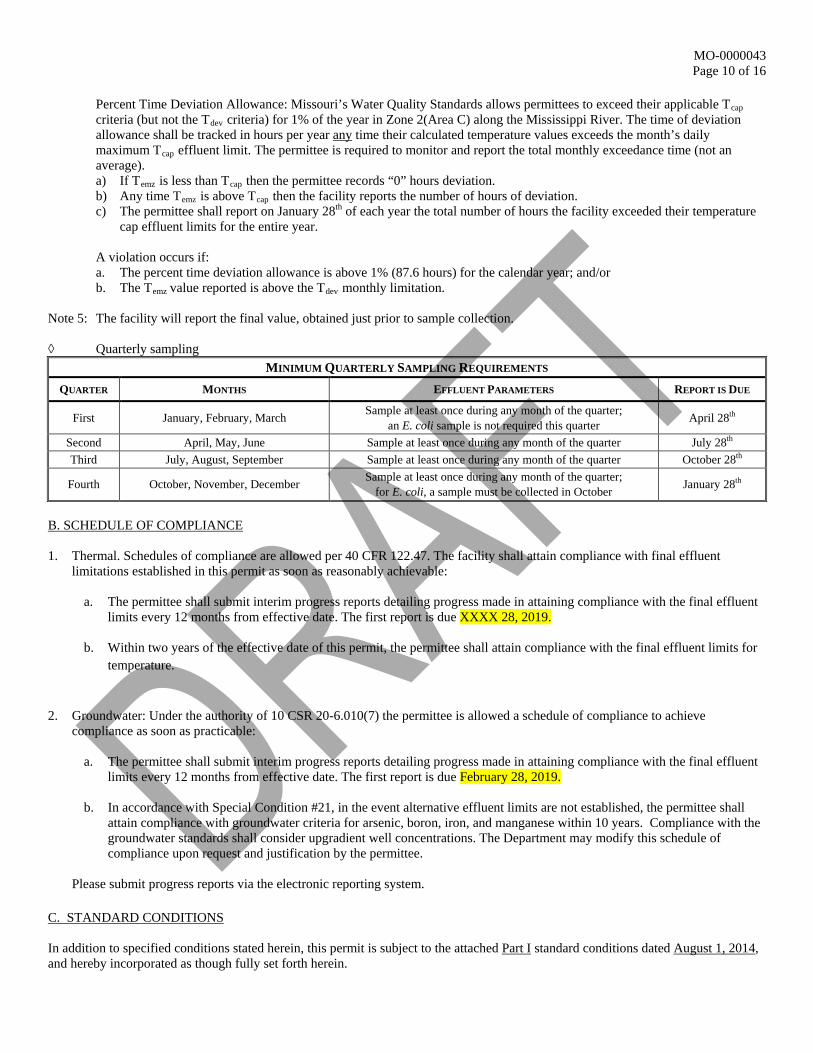
Percent Time Deviation Allowance: Missouri’s Water Quality Standards allows permittees to exceed their applicable Tcap criteria (but not the Tdev criteria) for 1% of the year in Zone 2(Area C) along the Mississippi River. The time of deviation allowance shall be tracked in hours per year any time their calculated temperature values exceeds the month’s daily maximum Tcap effluent limit. The permittee is required to monitor and report the total monthly exceedance time (not an average). a) If Temz is less than Tcap then the permittee records “0” hours deviation. b) Any time Temz is above Tcap then the facility reports the number of hours of deviation. c) The permittee shall report on January 28th of each year the total number of hours the facility exceeded their temperature
cap effluent limits for the entire year.
A violation occurs if: a. The percent time deviation allowance is above 1% (87.6 hours) for the calendar year; and/or b. The Temz value reported is above the Tdev monthly limitation.
Note 5: The facility will report the final value, obtained just prior to sample collection. ◊ Quarterly sampling
MINIMUM QUARTERLY SAMPLING REQUIREMENTS QUARTER MONTHS EFFLUENT PARAMETERS REPORT IS DUE
First January, February, March Sample at least once during any month of the quarter; an E. coli sample is not required this quarter April 28th
Second April, May, June Sample at least once during any month of the quarter July 28th Third July, August, September Sample at least once during any month of the quarter October 28th
Fourth October, November, December Sample at least once during any month of the quarter; for E. coli, a sample must be collected in October January 28th
B. SCHEDULE OF COMPLIANCE 1. Thermal. Schedules of compliance are allowed per 40 CFR 122.47. The facility shall attain compliance with final effluent
limitations established in this permit as soon as reasonably achievable:
a. The permittee shall submit interim progress reports detailing progress made in attaining compliance with the final effluent limits every 12 months from effective date. The first report is due XXXX 28, 2019.
b. Within two years of the effective date of this permit, the permittee shall attain compliance with the final effluent limits for
temperature.
2. Groundwater: Under the authority of 10 CSR 20-6.010(7) the permittee is allowed a schedule of compliance to achieve compliance as soon as practicable:
a. The permittee shall submit interim progress reports detailing progress made in attaining compliance with the final effluent limits every 12 months from effective date. The first report is due February 28, 2019.
b. In accordance with Special Condition #21, in the event alternative effluent limits are not established, the permittee shall attain compliance with groundwater criteria for arsenic, boron, iron, and manganese within 10 years. Compliance with the groundwater standards shall consider upgradient well concentrations. The Department may modify this schedule of compliance upon request and justification by the permittee.
Please submit progress reports via the electronic reporting system.
C. STANDARD CONDITIONS In addition to specified conditions stated herein, this permit is subject to the attached Part I standard conditions dated August 1, 2014, and hereby incorporated as though fully set forth herein.
MO-0000043 Page 11 of 16
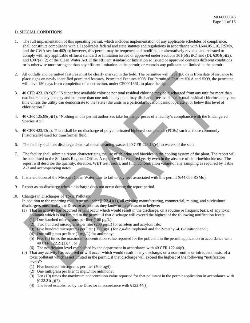
D. SPECIAL CONDITIONS 1. The full implementation of this operating permit, which includes implementation of any applicable schedules of compliance,
shall constitute compliance with all applicable federal and state statutes and regulations in accordance with §644.051.16, RSMo, and the CWA section 402(k); however, this permit may be reopened and modified, or alternatively revoked and reissued to comply with any applicable effluent standard or limitation issued or approved under Sections 301(b)(2)(C) and (D), §304(b)(2), and §307(a) (2) of the Clean Water Act, if the effluent standard or limitation so issued or approved contains different conditions or is otherwise more stringent than any effluent limitation in the permit; or controls any pollutant not limited in the permit.
2. All outfalls and permitted features must be clearly marked in the field. The permittee will have 180 days from date of issuance to place signs on newly identified permitted features, Permitted Features #008. For Permitted Feature #01A and #009, the permittee will have 180 days from completion of construction, under CP0001861, to place the sign.
3. 40 CFR 423.13(c)(2): “Neither free available chlorine nor total residual chlorine may be discharged from any unit for more than two hours in any one day and not more than one unit in any plant may discharge free available or total residual chlorine at any one time unless the utility can demonstrate to the [state] the units in a particular location cannot operate at or below this level of chlorination.”
4. 40 CFR 125.98(b)(1): “Nothing in this permit authorizes take for the purposes of a facility’s compliance with the Endangered Species Act.”
5. 40 CFR 423.13(a): There shall be no discharge of polychlorinated biphenyl compounds (PCBs) such as those commonly
[historically] used for transformer fluid.
6. The facility shall not discharge chemical metal cleaning wastes [40 CFR 423.13(e)] to waters of the state.
7. The facility shall submit a report characterizing the use of chlorine and biocides in the cooling system of the plant. The report will be submitted to the St. Louis Regional Office. A report will be required yearly even in the absence of chlorine/biocide use. The report will describe the quantity, duration, WET test results, and final concentration values of any sampling as required by Table A-3 and accompanying notes.
8. It is a violation of the Missouri Clean Water Law to fail to pay fees associated with this permit (644.055 RSMo). 9. Report as no-discharge when a discharge does not occur during the report period.
10. Changes in Discharges of Toxic Pollutant In addition to the reporting requirements under §122.41(1), all existing manufacturing, commercial, mining, and silvicultural dischargers must notify the Director as soon as they know or have reason to believe: (a) That an activity has occurred or will occur which would result in the discharge, on a routine or frequent basis, of any toxic
pollutant which is not limited in the permit, if that discharge will exceed the highest of the following notification levels: (1) One hundred micrograms per liter (100 µg/L); (2) Two hundred micrograms per liter (200 µg/L) for acrolein and acrylonitrile; (3) Five hundred micrograms per liter (500 µg/L) for 2,4-dinitrophenol and for 2-methyl-4, 6-dinitrophenol; (4) One milligram per liter (1 mg/L) for antimony; (5) Five (5) times the maximum concentration value reported for the pollutant in the permit application in accordance with
40 CFR 122.21(g)(7); or (6) The notification level established by the department in accordance with 40 CFR 122.44(f).
(b) That any activity has occurred or will occur which would result in any discharge, on a non-routine or infrequent basis, of a toxic pollutant which is not limited in the permit, if that discharge will exceed the highest of the following “notification levels”: (1) Five hundred micrograms per liter (500 µg/l); (2) One milligram per liter (1 mg/L) for antimony; (3) Ten (10) times the maximum concentration value reported for that pollutant in the permit application in accordance with
§122.21(g)(7). (4) The level established by the Director in accordance with §122.44(f).
MO-0000043 Page 12 of 16
D. SPECIAL CONDITIONS (continued)
11. Reporting of Non-Detects
(a) An analysis conducted by the permittee or their contracted laboratory shall be conducted in such a way that the precision and accuracy of the analyzed result can be enumerated.
(b) The permittee shall not report a sample result as “Non-Detect” without also reporting the detection limit of the test. Reporting as “Non-Detect” without also including the detection limit will be considered failure to report, which is a violation of this permit.
(c) The permittee shall report the “Non-Detect” result using the less than sign and the minimum detection limit (e.g. <10). (d) Where the permit contains a Minimum Level (ML) and the permittee is granted authority in the permit to report zero in lieu
of the < ML for a specified parameter (conventional, priority pollutants, metals, etc.), then zero (0) is to be reported for that parameter.
(e) See Standard Conditions Part I, Section A, #4 regarding proper detection limits used for sample analysis. (f) When calculating monthly averages, one-half of the minimum detection limit (MDL) should be used instead of a zero.
Where all data are below the MDL, the “<MDL” shall be reported as indicated in item (C).
12. Any pesticide discharge from any point source shall comply with the requirements of Federal Insecticide, Fungicide and Rodenticide Act, as amended (7 U.S.C. 136 et. seq.) and the use of such pesticides shall be in a manner consistent with its label.
13. To protect the general criteria found at 10 CSR 20-7.031(4), before releasing water accumulated in secondary containment areas which contain petroleum products, it must be examined for hydrocarbon odor and presence of sheen. If the presence of odor or sheen is indicated, the water shall be treated using an appropriate method or disposed of in accordance with legally approved methods, such as being sent to a wastewater treatment facility. Following treatment, the water shall be tested for oil and grease, benzene, toluene, ethylbenzene, and xylene using 40 CFR part 136 methods. All pollutant levels must be below the most protective, applicable standards for the receiving stream, found in 10 CSR 20-7.031 Table A. Records of all testing and treatment of water accumulated in secondary containment shall be stored in the SWPPP to be available on demand to DNR and EPA personnel.
14. Release of a hazardous substance must be reported to the department in accordance with 10 CSR 24-3.010. A record of each reportable spill shall be retained with the SWPPP and made available to the department upon request.
15. The purpose of the SWPPP and the BMPs listed herein is the prevention of pollution of waters of the state. A deficiency of a
BMP means it was not effective in preventing pollution [10 CSR 20-2.010(56)] of waters of the state, and corrective actions means the facility took steps to eliminate the deficiency.
16. Substances regulated by federal law under the Resource Conservation and Recovery Act (RCRA) and Comprehensive
Environmental Response, Compensation, and Liability Act (CERCLA), that are transported, stored, or used for maintenance, cleaning or repair, shall be managed according to RCRA and CERCLA. Ameren is exempt from Clean Water Act, Section 311, reporting for sodium hydroxide, sodium hypochlorite, sulfuric acid and hydrazine as per 40 CFR 117.12.
17. The facility’s SIC codes found in 40 CFR 122.26(b)(14) and/or 10 CSR 20-6.200(2) indicate they shall implement a SWPPP
which must be prepared and implemented upon 90 days from permit issuance. The SWPPP must be kept on-site and should not be sent to the department unless specifically requested. The SWPPP must be reviewed and updated every five (5) years or as site conditions change (see Rationale and Derivation: antidegradation analysis, and SWPPP in the fact sheet). The permittee shall select, install, use, operate, and maintain the Best Management Practices prescribed in the SWPPP in accordance with the concepts and methods described in: Developing Your Stormwater Pollution Prevention Plan, A Guide for Industrial Operators, (EPA 833-B-09-002) published by the EPA in February 2009 (www.epa.gov/npdes/pubs/industrial_swppp_guide.pdf). In addition to areas with industrial exposure, the facility must include the barge area, the road intended to transport dry-handled ash to the utility waste landfill, the railroad, Outfall #004, and Outfall #005 in the SWPPP. The SWPPP must include: (a) A listing of specific contaminants and their control measures (or BMPs) and a narrative explaining how BMPs are
implemented to control and minimize the amount of contaminants potentially entering stormwater. The BMPs should be designed to treat the stormwater up to the 10 year, 24 hour rain event.
(b) For new, altered, or expanded stormwater discharges, the SWPPP shall identify reasonable and effective BMPs while accounting for environmental impacts of varying control methods. The antidegradation analysis must document why no discharge or no exposure options are not feasible. The selection and documentation of appropriate control measures shall serve as an alternative analysis of technology and fulfill the requirements of antidegradation [10 CSR 20-7.031(3)]. Failure to implement and maintain the chosen BMP is a permit violation. For further guidance, consult the antidegradation implementation procedure at http://dnr.mo.gov/env/wpp/docs/AIP050212.pdf.
MO-0000043 Page 13 of 16
D. SPECIAL CONDITIONS (continued)
(c) The SWPPP must include a schedule for once per month site inspections and brief written reports. The inspection report must include precipitation information for the entire period since last inspection, as well as observations and evaluations of BMP effectiveness. Throughout coverage under this permit, the facility must perform ongoing SWPPP review and revision to incorporate any site condition changes. i. Operational deficiencies must be corrected within seven (7) calendar days.
ii. Minor structural deficiencies must be corrected within fourteen (14) calendar days. iii. Major structural deficiencies must be reported to the regional office within seven (7) days of discovery. The initial report
shall consist of the deficiency noted, the proposed remedies, the interim or temporary remedies (including the general timing of the placement of the interim measures), and an estimate of the timeframe needed to wholly complete the repairs or construction. The permittee will work with the regional office to determine the best course of action, including but not limited to temporary structures to control stormwater runoff. The facility shall correct the major structural deficiency as soon as reasonably achievable.
iv. All actions taken to correct the deficiencies shall be included with the written report, including photographs. v. Inspection reports must be kept on site with the SWPPP and maintained for a period of five (5) years. These must be
made available to department and EPA personnel upon request. (d) A provision for designating an individual to be responsible for environmental matters. (e) A provision for providing training to all personnel involved in material handling and storage, and housekeeping of
maintenance and cleaning areas. Proof of training shall be submitted on request of the department.
18. Permittee shall adhere to the following minimum Best Management Practices (BMPs): (a) Prevent the spillage or loss of fluids, oil, grease, fuel, etc. from vehicle maintenance, equipment cleaning, or warehouse
activities and thereby prevent the contamination of stormwater from these substances. (b) Provide collection facilities and arrange for proper disposal of waste products including but not limited to petroleum waste
products, and solvents. (c) Store all paint, solvents, petroleum products and petroleum waste products (except fuels), and storage containers (such as
drums, cans, or cartons) so these materials are not exposed to stormwater or provide other prescribed BMPs such as plastic lids and/or portable spill pans to prevent the commingling of stormwater with container contents. Commingled water may not be discharged under this permit. Provide spill prevention control, and/or management sufficient to prevent any spills of these pollutants from entering waters of the state. Any containment system used to implement this requirement shall be constructed of materials compatible with the substances contained and shall also prevent the contamination of groundwater.
(d) Provide good housekeeping practices on the site to keep trash from entry into waters of the state. (e) Provide sediment and erosion control sufficient to prevent or control sediment loss off of the property. This could include the
use of straw bales, silt fences, or sediment basins, if needed, to comply with effluent limits or benchmarks. (f) Ensure adequate provisions are provided to prevent surface water intrusion into the storage basin, to divert stormwater runoff
around the storage basin, and to protect embankments from erosion.
19. Impingement and Entrainment: CWA§ 316(b) Cooling Water Intake Structure (a) The facility is required to continue operating in a manner minimizing impingement and entrainment until the permittee has
submitted the renewal application required in 40 CFR 122.21 and 40 CFR 125 Subpart J and best technology available is established in accordance with Clean Water Act §316(b) regulations. CWA § 316(b) regulations require modifications to reduce impingement and entrainment caused by intake structures.
(b) The facility shall follow 40 CFR 122.21 and 40 CFR 125 Subpart J regulations regarding reduction in impingement and entrainment and performing their associated studies.
(c) The facility shall submit annual status reports by February 28 each year, detailing the progress of the previous year. (d) Six months prior to permit expiration, the facility shall submit their application for 316(b) detailing the results of the
biomonitoring studies and the selected path forward for implementing impingement and entrainment modifications at the intake structure.
(e) This permit may be reopened and modified, or alternatively, revoked and reissued to incorporate new or modified requirements applicable to existing cooling water intake structures under Section 316(b) of the Clean Water Act. In the event it is necessary for this permit to be reopened and modified, or alternatively revoked and reissued, permittee shall comply with any such new or modified requirements or standards applicable to existing cooling water intake structures under §316(b) of the Clean Water Act.
MO-0000043 Page 14 of 16
D. SPECIAL CONDITIONS (continued) 20. Groundwater Monitoring:
a) The department has the right to insist additional wells be installed at any time. b) New, moved, or closed groundwater wells must be codified in permit through permit modification. c) Groundwater monitoring wells shall be maintained and closed in accordance with 10 CSR 23 Chapter 4 to protect waters of
the state. d) If a well cannot be sampled for any reason, the permittee may report “no-discharge”. An explanation shall be provided to the
department at that time. e) The department may also modify the permit to change the sampling parameters incorporated within this permit at any time. f) The permittee shall implement an effective groundwater monitoring program designed to determine if the coal ash
impoundments have or had an impact on groundwater quality. The monitoring system must be capable of comparing up-gradient to down-gradient water quality in the first continuous water-bearing zone beneath the impoundment. The monitoring system must be based upon a thorough hydrogeological characterization of the impoundment area that determines the appropriate hydrostratigraphic unit to monitor, its groundwater gradient(s) and any seasonal variations in its gradient(s). Any hydrogeological characterization conducted for the design of the groundwater monitoring program shall be approved by the department’s Missouri Geological Survey and must be conducted under the guidance of a geologist registered in the State of Missouri. The number of monitoring wells required for the groundwater monitoring program shall be based on site-specific hydrogeologic conditions and sufficient for effective monitoring of the site. To complete the following work plans and reports, the Water Protection Program recommends using applicable portions of the document issued by the Missouri Geological Survey (MGS), dated December 10, 2010 (or newer), (Draft) Guidance for Conducting a Detailed Hydrogeologic Site Characterization and Designing a Groundwater Monitoring Program as guidance. The plans shall be submitted as two hard copies and one electronic copy to the Missouri Department of Natural Resources central office: The Water Protection Program at P.O. Box 176, Jefferson City MO 65102-9920. In order to accomplish this, the permittee shall: (1) By 6 months from the effective date of this permit (or sooner), submit a Site Characterization Workplan to the Central
Office for approval. (2) By 27 months from the effective date of this permit (or sooner), submit a Site Characterization Report detailing the
findings from completion of the Site Characterization Workplan to the Central Office for verification of conclusions. (3) By 30 months from the effective date of this permit (or sooner), submit a draft Groundwater Monitoring, Sampling, and
Analysis Plan (GMSAP) to the Central Office for approval. (4) By 36 months from the effective date of this permit (or sooner), submit a final Groundwater Monitoring, Sampling, and
Analysis Plan (GMSAP) to the Central Office for approval. The design of the groundwater monitoring network should be approved by the department prior to installation. However, if installation occurs prior to approval, the WPP and MGS reserves the right to insist on additional wells or changes to the network.
(5) By 48 months from the effective date of this permit (or sooner), have all elements of the GMSAP fully implemented. The permittee shall collect groundwater quality samples at a discrete interval (usually quarterly) which must demonstrate each sample is independent and representative of the groundwater being monitored. A minimum of 8 groundwater quality samples must be collected prior to the expiration of the permit.
21. Groundwater Compliance: a) The permittee shall attain compliance with groundwater criteria listed in 10 CSR 20-7.031 for arsenic, boron, iron, and
manganese as specified by the limits below.
Parameter Units Final Limits Arsenic, Total Recoverable µg/L 50 Boron, Total Recoverable µg/L 2,000 Iron, Total Recoverable µg/L 300 Manganese µg/L 50
Limits for these pollutants shall be attained at all monitoring wells established through a Groundwater Monitoring, Sampling, and Analysis Plan approved by the Department of Natural Resources; or
b) The permittee shall demonstrate, at the direction of the Department of Natural Resources, that the impact on the water quality in the aquifer is negligible on the beneficial uses in accordance with 10 CSR 7.015(7)(F). If the demonstrations show that the impact on groundwater quality will not result in an unreasonable risk to human health or the environment, alternate effluent limitations will be established in this permit.
MO-0000043 Page 15 of 16
D. SPECIAL CONDITIONS (continued)
22. Whole Effluent Toxicity (WET) Tests shall be conducted as follows:
• For Outfall #001 (acute test), the AEC is 66%; the dilution series is 83%, 66%, 55%, 27.5%, and 14%. • WET tests on Outfall #001 must be conducted concurrently of biocide use. • For Outfalls #01A, and #002 (chronic tests), the AEC is 100%; the dilution series is: 80%, 40%, 20%, 10%, and 5%.
23. Acute Whole Effluent Toxicity (WET) tests shall be conducted as follows: (Outfall #001) (a) Freshwater Species and Test Methods: Species and short-term test methods for estimating the acute toxicity of NPDES
effluents are found in the most recent edition of Methods for Measuring the Acute Toxicity of Effluents and Receiving Waters to Freshwater and Marine Organisms (EPA/821/R-02/012; Table IA, 40 CFR Part 136). The permittee shall concurrently conduct 48-hour, static, non-renewal toxicity tests with the following species: o The fathead minnow, Pimephales promelas (Acute Toxicity EPA Test Method 2000.0). o The daphnid, Ceriodaphnia dubia (Acute Toxicity EPA Test Method 2002.0).
(b) Chemical and physical analysis of the upstream control sample and effluent sample shall occur immediately upon being received by the laboratory, prior to any manipulation of the effluent sample beyond preservation methods consistent with federal guidelines for WET testing that are required to stabilize the sample during shipping. Where upstream receiving water is not available or known to be toxic, other approved control water may be used.
(c) Test conditions must meet all test acceptability criteria required by the EPA Method used in the analysis. (d) All chemical and physical analysis of the effluent sample performed in conjunction with the WET test shall be performed at the
100% effluent concentration. (e) All chemical analyses shall be performed and results shall be recorded in the appropriate field of the report form. The
parameters for chemical analysis include Temperature (°F), pH (SU), Conductivity (µmohs/cm), Dissolved Oxygen (mg/L), Total Residual Chlorine (µg/L), free available chlorine (µg/L), total alkalinity (mg/L), and total hardness (mg/L).
(f) The facility must submit a full laboratory report for all toxicity testing. The report must include a quantification of acute toxic units (TUa = 100/LC50) reported according to the test methods manual chapter on report preparation and test review. The Lethal Concentration 50 Percent (LC50) is the effluent concentration that would cause death in 50 percent of the test organisms at a specific time.
24. Chronic Whole Effluent Toxicity (WET) tests shall be conducted as follows: (Outfalls #01A & 002) (a) Freshwater Species and Test Methods: Species and short-term test methods for estimating the acute toxicity of NPDES
effluents are found in the most recent edition of Short-term Methods for Estimating the Chronic Toxicity of Effluents and Receiving Waters to Freshwater Organisms (EPA/821/R-02/013; Table IA, 40 CFR Part 136). The permittee shall concurrently conduct 7-day, static, renewal toxicity tests with the following species: o The fathead minnow, Pimephales promelas (Survival and Growth Test Method 1000.0). o The daphnid, Ceriodaphnia dubia (Survival and Reproduction Test Method 1002.0).
(b) Chemical and physical analysis of the upstream control sample and effluent sample shall occur immediately upon being received by the laboratory, prior to any manipulation of the effluent sample beyond preservation methods consistent with federal guidelines for WET testing that are required to stabilize the sample during shipping. Where upstream receiving water is not available or known to be toxic, other approved control water may be used.
(c) Test conditions must meet all test acceptability criteria required by the EPA Method used in the analysis. (d) All chemical and physical analysis of the effluent sample performed in conjunction with the WET test shall be performed at
the 100% effluent concentration. (e) All chemical analyses shall be performed and results shall be recorded in the appropriate field of the report form. The
parameters for chemical analysis are: Temperature (°F), pH (SU), Conductivity (µmohs/cm), Dissolved Oxygen (mg/L), Total Residual Chlorine (mg/L), Sulfates Plus Chlorides (mg/L), and Total Hardness (mg/L).
(f) The facility must submit a full laboratory report for all toxicity testing. The report must include a quantification of chronic toxic units (TUc = 100/IC25) reported according to the Methods for Measuring the Chronic Toxicity of Effluents and Receiving Waters to Freshwater and Marine Organisms chapter on report preparation and test review. The 25 percent Inhibition Effect Concentration (IC25) is the toxic or effluent concentration that would cause 25 percent reduction in mean young per female or in growth for the test populations.
25. Electronic Discharge Monitoring Report (eDMR) Submission System.
(a) Discharge Monitoring Reporting Requirements. The permittee must electronically submit compliance monitoring data via the eDMR system. In regards to Standard Conditions Part I, Section B, #7, the eDMR system is currently the only Department approved reporting method for this permit.
(b) Programmatic Reporting Requirements. The following reports (if required by this permit) must be electronically submitted as an attachment to the eDMR system until such a time when the current or a new system is available to allow direct input of the data:
MO-0000043 Page 16 of 16
(1) Schedule of Compliance Progress Reports; (2) CWA Section 316(b) Annual Reports; and (3) Any additional report required by the permit excluding bypass reporting. After such a system has been made available by the department, required data shall be directly input into the system by the next report due date.
(c) Other actions. The following shall be submitted electronically after such a system has been made available by the department: (1) General Permit Applications/Notices of Intent to discharge (NOIs); (2) Notices of Termination (NOTs); (3) No Exposure Certifications (NOEs); and (4) Low Erosivity Waivers and Other Waivers from Stormwater Controls (LEWs).
(d) Electronic Submissions. To access the eDMR system, use the following link in your web browser: https://edmr.dnr.mo.gov/edmr/E2/Shared/Pages/Main/Login.aspx.
(e) Waivers from Electronic Reporting. The permittee must electronically submit compliance monitoring data and reports unless a waiver is granted by the department in compliance with 40 CFR Part 127. The permittee may obtain an electronic reporting waiver by first submitting an eDMR Waiver Request Form: http://dnr.mo.gov/forms/780-2692-f.pdf. The department will either approve or deny this electronic reporting waiver request within 120 calendar days. Only permittees with an approved waiver request may submit monitoring data and reports on paper to the Department for the period that the approved electronic reporting waiver is effective.
Ameren Missouri Rush Island Energy Center MO-0000043, Jefferson County Factsheet, Page 1
MISSOURI DEPARTMENT OF NATURAL RESOURCES
FACT SHEET FOR THE PURPOSE OF RENEWAL
OF MO-0000043
AMEREN MISSOURI-RUSH ISLAND ENERGY CENTER
The Federal Water Pollution Control Act ("Clean Water Act" Section 402 Public Law 92-500 as amended) established the National Pollution Discharge Elimination System (NPDES) permit program. This program regulates the discharge of pollutants from point sources into the waters of the United States, and the release of stormwater from certain point sources. All such discharges are unlawful without a permit (Section 301 of the "Clean Water Act"). After a permit is obtained, a discharge not in compliance with all permit terms and conditions is unlawful. Missouri State Operating Permits (MSOPs) are issued by the Director of the Missouri Department of Natural Resources (Department) under an approved program, operating in accordance with federal and state laws (Federal "Clean Water Act" and "Missouri Clean Water Law" Section 644 as amended). MSOPs are issued for a period of five (5) years unless otherwise specified for less. As per [40 CFR Part 124.8(a)] and [10 CSR 20-6.020(1)2.] a factsheet shall be prepared to give pertinent information regarding the applicable regulations, rationale for the development of effluent limitations and conditions, and the public participation process for the Missouri State Operating Permit (MSOP or operating permit) listed below. A factsheet is not an enforceable part of an operating permit. Part I. FACILITY INFORMATION Facility Type: Major, Categorical Industrial Facility SIC Code(s): 4911 Facility NAICS Code: 221112 Application Date: 03/30/2009; addendums submitted 03/03/2011; 08/11/2016; 06/20/2017; & 06/27/2017 Expiration Date: 09/30/2009 Last Inspection: 04/13/2016 in compliance FACILITY DESCRIPTION: The Ameren Missouri – Rush Island Power Plant (Facility) is an electrical generating establishment primarily engaged in the generation of electricity for distribution and sale which results primarily form the processing of a fossil fuel (coal). The facility commenced operations in 1976 and the two coal-fired boilers produce steam for the generation of approximately 1250MWe. This facility has eight (8) designated outfalls. In addition to the narrative description below for each of the eight (8) outfalls, there is a flow diagram for the outfalls located within the factsheet. Rush Island is considered a major facility under the department’s air program (2909900016) and is a small quantity generator under the Hazardous Waste Program (MOD079888871). Following completion of construction of the new detention basin and the low volume waste basins, discharges from the ash pond, Outfall #002 will be reduced to an intermittent discharge. Outfall #009 will be the emergency spillway discharge Outfall #001 – Non-contact Cooling Water: Outfall #001 discharges once-through cooling water that is withdrawn from the Mississippi River. The cooling water is passed through condensers and other heat exchangers and is discharged to the Mississippi River. Portions of the cooling water system are intermittently treated with biocides, which is discussed below. The cooling water also is used to lubricate the circulating water pump bearings in the intake structure. This lube water mixes with the normal pump flow and is component of the average outfall flow (less than 0.02% of the discharge flow). The permittee’s current approach to Macroinvertebrate Control consists of molluscicide treatment of intake structures cells, auxiliary coolers (condensate, condensers, jacket water coolers), and high and low pressure untreated (raw) water systems using commercial product. The use of the commercial products may cause the need for a Federal (EPA) pesticide permit.
Ameren Missouri-Rush Island Energy Center Fact Sheet Page 2 of 51
Outfall #01A-Low Volume Wastewater Treatment: Outfall #01A is a new outfall for the release of low volume wastewater. Outfall #01A was constructed to handle low volume process wastewater flows with the planned closure of the ash ponds, Outfall #002. As Outfall #01A will replace and manage the process wastewater from Outfall #002, an Antidegradation review was not required as the overall flows at the plant will be reduced with the change to a dry handling ash system, closure of the ash pond, and the new low volume treatment basins. Outfall #002 – Ash Pond: Outfall #002 is the discharge from the facility’s wastewater treatment pond that provides treatment for fly ash and bottom ash sluice water, other low volume wastes, coal pile run-off and stormwater run-off via sedimentation and neutralization. This facility generates approximately 83,000 tons of bottom ash and 194,000 tons of fly ash per year. Fly ash is conveyed dry to silos or wet sluiced to the ash pond and bottom ash is conveyed to the ash pond from which they can be respectively recovered for beneficial use projects. During 2008, approximately 334,000 tons of fly ash and 6,000 tons of bottom ash were marketed for beneficial uses. Other sources of wastewater that are discharged from Outfall #002 include: Mill Pyrite Removal System; Bottom Ash Removal System; Fly Ash Removal System; Demineralizer Sump; Coal Reclaim Tunnel Sump; and Coal Pile Run-off. During this permit cycle, this outfall will transition from a process outfall to an intermittent stormwater outfall as closure of the ash ponds occur. Ameren is converting to a dry handling system for ash and is constructing a new treatment basin, Outfall #01A for the low volume wastewater. The construction of the new basins is expected to be completed in late 2018 and the complete closure and capping of the ash ponds occurring after that. Outfall #003 – Sewage Treatment Plant: This outfall consists of treated domestic wastewater from an extended aeration Sewage Treatment Plant (STP). Domestic wastewater from the whole facility is treated at the STP. Upgrades to the existing STP, including construction of a new lift station, ultraviolet disinfection and flow equalization were completed in 2011, under CP No. 22-7685. Outfall #004 – Stormwater run-off: Stormwater run-off from this outfall consists of the following areas:
• Yard areas east of the storeroom and north of the plant, including the switchyard; • Roof drains from the administration building and the “Unit 2” side of the turbine building; • Storeroom lay-down area and loading dock ramp; • Area around the northwest corner of the power block near the electrical/maintenance shop addition; • Northeast and northwest corners of the employees parking lot north of the switchyard; and • Portions of the plant access road.
No process wastewater sources are included in this stormwater outfall. However, there are other seasonal or infrequent sources contributing to this outfall, which are the result of surface washes using treated water without detergents:
• Air conditional coils; • Exterior building surfaces; and • Yard areas contributory to Outfall #004.
Outfall #008 – Ash Pond Emergency Spillway Following a dam safety review, the Department requested that an emergency spillway be installed at the ash pond in a letter dated June 20, 2010. Registration Permit R-494 was issued by the Dam and Reservoir Safety Program for the emergency spillway on December 23, 2010. It is not expected that this outfall will discharge, except under catastrophic conditions. However, should such a situation arise, this outfall would discharge from the western berm of the ash pond into Isle du Bois Creek just upstream of its confluence with the Mississippi River. Permitted Feature #009-Detention Basin Emergency Overflow The new detention basin is covered under CP0001861. The detention basin will receive stormwater from the coal yard and process wastewater from a large portion of the Rush Island Energy Center. The detention basin will receive flows when excess flows are received at the low volume wastewater treatment basin, Outfall #01A. During normal operations, flows received in the detention basin will be treated and discharged through Outfall #01A.
Ameren Missouri-Rush Island Energy Center Fact Sheet Page 3 of 51
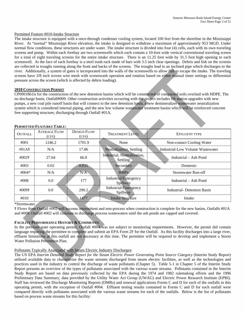
Permitted Feature #010-Intake Structure The intake structure is equipped with a once-through condenser cooling system, located 100 feet from the shoreline in the Mississippi River. At “normal” Mississippi River elevation, the intake is designed to withdraw a maximum of approximately 953 MGD. Under normal flow conditions, these structures are under water. The intake structure is divided into four (4) cells, each with its own traveling screens and pump. Within each forebay are two screenwells which each contain a 10-foot wide vertical conventional traveling screen for a total of eight traveling screens for the entire intake structure. There is an 11.25 foot wide by 31.5 foot high opening to each screenwell. At the face of each forebay is a steel trash rack made of bars with 3.5 inch clear openings. Debris and fish on the screens are collected in troughs running along the front and backs of the screens. The troughs lead to an inclined pipe which discharges to the river. Additionally, a system of gates is incorporated into the walls of the screenwells to allow fish to escape the intake. The traveling screens have 3/8 inch woven wire mesh with screenwash operation and rotation based on either manual timer settings or differential pressure across the screen (which is affected by debris loading). 2018 CONSTRUCTION PERMIT CP0001861is for the construction of the new detention basins which will be constructed of compacted soils overlaid with HDPE. The no discharge basin, Outfall#009. Other construction activities occurring with the project includes lift station upgrades with new pumps, a new coal pile runoff basin that will connect to the new detention basin, a new demineralizer wastewater neutralization system which is considered internal piping, and the new low volume wastewater treatment basins which will be reinforced concrete free supporting structure, discharging through Outfall #01A. PERMITTED FEATURES TABLE:
OUTFALL AVERAGE FLOW (CFS)
DESIGN FLOW (CFS) TREATMENT LEVEL EFFLUENT TYPE
#001 1246.2 1701.9 None Non-contact Cooling Water
#01AϮ N/A 17.86 Neutralization, Settling Industrial-Low Volume Wastewater
#002Ϯ 27.64 66.8 Industrial, Neutralization, Settling Industrial – Ash Pond
#003 0.02 0.031 Secondary Domestic
#004* N/A N/A BMPs Stormwater Run-off
#008 0.0 177 Industrial/Emergency Spillway Industrial – Ash Pond
#009Ϯ 0.0 290.2 Industrial/Emergency Spillway Industrial- Detention Basin
#010 1477 Intake Structure Intake *Stormwater Ϯ Flows from Outfall #002 will become intermittent and non-process when construction is complete for the new basins, Outfalls #01A and #009. Outfall #002 will continue to discharge process wastewaters until the ash ponds are capped and covered. FACILITY PERFORMANCE HISTORY & COMMENTS: In the previous state operating permit, Outfall #004 was not subject to monitoring requirements. However, the permit did contain language requiring the permittee to complete and submit an EPA Form 2F for the Outfall. As this facility discharges into a large river, effluent limitations at this outfall are not necessary at this time. The permittee will be required to develop and implement a Storm Water Pollution Prevention Plan. Pollutants Typically Associated with Steam Electric Industry Discharges: The US EPA Interim Detailed Study Report for the Steam Electric Power Generating Point Source Category (Interim Study Report) utilized available data to characterize the waste streams discharged from steam electric facilities, as well as the technologies and practices used in the industry to control the discharge of waste pollutants (Chapter 5). Table 5-1 in Chapter 5 of the Interim Study Report presents an overview of the types of pollutants associated with the various waste streams. Pollutants contained in the Interim Study Report are based on data previously collected by the EPA during the 1974 and 1982 rulemaking efforts and the 1996 Preliminary Data Summary, data provided by the Utility Water Act Group (UWAG) and Electric Power Research Institute (EPRI). Staff has reviewed the Discharge Monitoring Reports (DMRs) and renewal applications Forms C and D for each of the outfalls in this operating permit, with the exception of Outfall #004. Effluent testing results contained in Forms C and D for each outfall were compared directly with pollutants associated with the various waste streams for each of the outfalls. Below is the list of pollutants based on process waste streams for this facility:
Ameren Missouri-Rush Island Energy Center Fact Sheet Page 4 of 51
• Cooling Water: Once-Through or Cooling Tower Blowdown (Outfall #001):
Chlorine, Iron, Copper, Nickel, Aluminum, Boron, Chlorinated Organic Compounds, Suspended Solids, Brominated Compounds, and Non-Oxidizing Biocides.
• Ash Handling: Bottom or Fly Ash (Outfall #002):
TSS, Sulfate, Chloride, Magnesium, Nitrate, Aluminum, Antimony, Arsenic, Boron, Cadmium, Chromium, Copper, Cyanide, Iron, Lead, Mercury, Nickel, Selenium, Silver, Thallium, Vandium, and Zinc.
• Coal Pile Runoff (Outfall #002):
Acidity, COD, Chloride, Sulfate, TSS, Aluminum, Antimony, Arsenic, Boron, Beryllium, Cadmium, Chromium, Copper, Iron, Lead, Manganese, Mercury, Nickel, Selenium, Silver, Thallium, Vandium, and Zinc.
• Other Low-Volume Waste Streams (Outfalls #001and 002):
Suspended Solids, Dissolved Solids, Oil and Grease, Phosphates, Surfactants, Acidity, Methylene Chloride, Phthalates, BOD5, COD, Fecal Coliform and Nitrates.
For the above pollutants, staff drafting this operating permit only compared the applicable pollutants based on Missouri’s Water Quality Standards criteria and designated uses. For any of the outfalls that do not contain one of the process wastewater types above, these pollutants were not reviewed (i.e., Outfalls #003 and 004). For Outfall #003, staff drafting this permit and fact sheet reviewed the applicable Forms C and D to determine if effluent from this outfall had potential to exceed Missouri’s Water Quality Standards for the tested pollutants. For Outfall #004, Form 2F was reviewed. MAJOR WATER USER: From the department’s Water Resources Program, Rush Island is a listed major water user (099200011) and has a registration permit for the ash pond (R-494).
Ameren Missouri-Rush Island Energy Center Fact Sheet Page 5 of 51
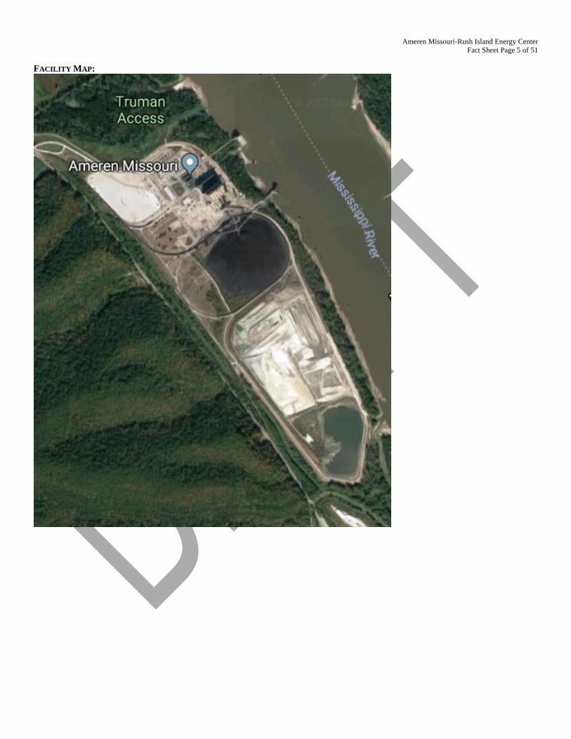
FACILITY MAP:
Ameren Missouri-Rush Island Energy Center Fact Sheet Page 6 of 51
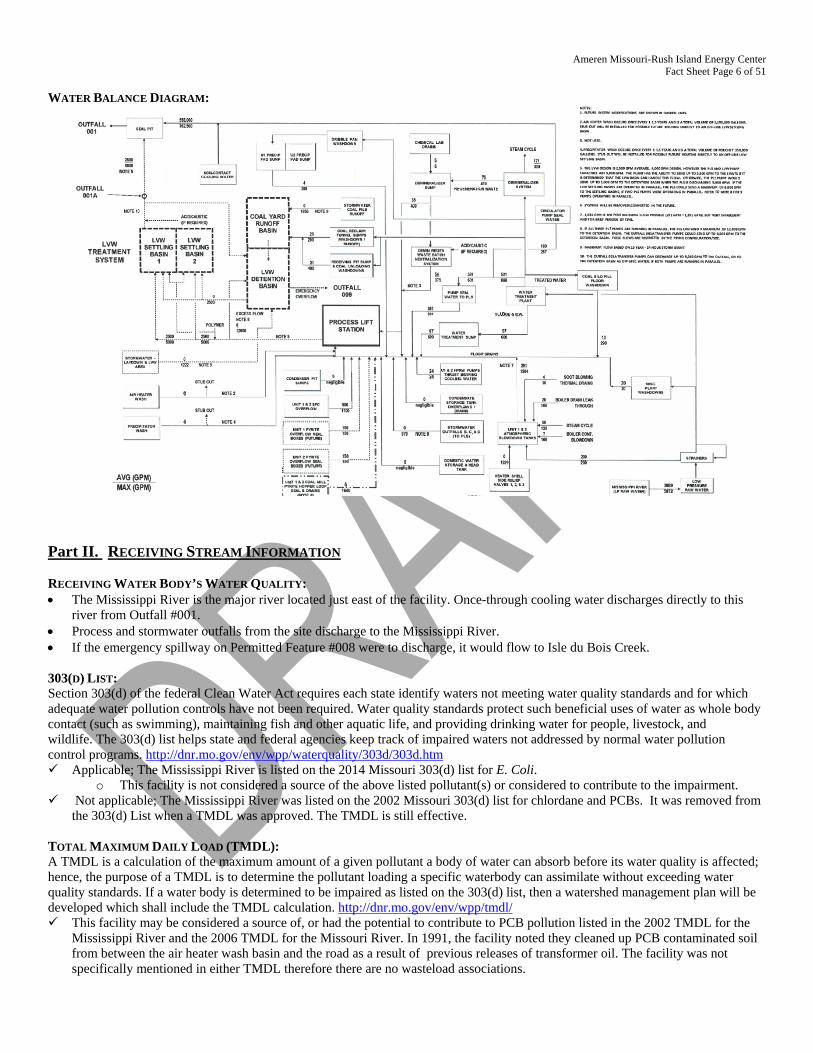
WATER BALANCE DIAGRAM:
Part II. RECEIVING STREAM INFORMATION RECEIVING WATER BODY’S WATER QUALITY: • The Mississippi River is the major river located just east of the facility. Once-through cooling water discharges directly to this
river from Outfall #001. • Process and stormwater outfalls from the site discharge to the Mississippi River. • If the emergency spillway on Permitted Feature #008 were to discharge, it would flow to Isle du Bois Creek. 303(D) LIST: Section 303(d) of the federal Clean Water Act requires each state identify waters not meeting water quality standards and for which adequate water pollution controls have not been required. Water quality standards protect such beneficial uses of water as whole body contact (such as swimming), maintaining fish and other aquatic life, and providing drinking water for people, livestock, and wildlife. The 303(d) list helps state and federal agencies keep track of impaired waters not addressed by normal water pollution control programs. http://dnr.mo.gov/env/wpp/waterquality/303d/303d.htm Applicable; The Mississippi River is listed on the 2014 Missouri 303(d) list for E. Coli.
o This facility is not considered a source of the above listed pollutant(s) or considered to contribute to the impairment. Not applicable; The Mississippi River was listed on the 2002 Missouri 303(d) list for chlordane and PCBs. It was removed from
the 303(d) List when a TMDL was approved. The TMDL is still effective.
TOTAL MAXIMUM DAILY LOAD (TMDL): A TMDL is a calculation of the maximum amount of a given pollutant a body of water can absorb before its water quality is affected; hence, the purpose of a TMDL is to determine the pollutant loading a specific waterbody can assimilate without exceeding water quality standards. If a water body is determined to be impaired as listed on the 303(d) list, then a watershed management plan will be developed which shall include the TMDL calculation. http://dnr.mo.gov/env/wpp/tmdl/ This facility may be considered a source of, or had the potential to contribute to PCB pollution listed in the 2002 TMDL for the
Mississippi River and the 2006 TMDL for the Missouri River. In 1991, the facility noted they cleaned up PCB contaminated soil from between the air heater wash basin and the road as a result of previous releases of transformer oil. The facility was not specifically mentioned in either TMDL therefore there are no wasteload associations.
Ameren Missouri-Rush Island Energy Center Fact Sheet Page 7 of 51
o PCBs were used in transformer oil because of their excellent heat dispersion capabilities. On August 25, 1982, EPA issued a
final rule governing the use and servicing of electrical equipment containing PCBs (47 FR 37342). This final rule was issued as a result of the Court's decision to strike down the May 1979 rule's classification of transformers, capacitors, and electromagnets as "totally enclosed." In the August 25, 1982 rule, EPA authorized the use of electrical equipment containing PCBs with certain conditions and restrictions intended to minimize human and environmental exposures to PCBs. On October 21, 1982, EPA issued part one of a two-part rule to address the 50 ppm regulatory cutoff (47 FR 46980). This final rule addressed closed and controlled waste manufacturing processes. EPA submitted a plan to the Court on November 1, 1982, that requested a further extension of the stay of mandate for the 50 ppm cutoff and presented plans for the completion of the rulemaking on this issue. (The October 21, 1982 rule was superseded later by the "Uncontrolled PCB's Rule" issued on July 10, 1984.). Since then, utilities have been retrofitting all transformers and filling with mineral oil which does not contain PCBs. It is unknown if Rush Island has any remaining transformers which may have PCBs or if spills of PCBs occurred on site.
APPLICABLE DESIGNATIONS OF WATERS OF THE STATE: As per Missouri’s Effluent Regulations [10 CSR 20-7.015(1)(B)], the waters of the state are divided into the following seven
categories. Each category lists effluent limitations for specific parameters, which are presented in each outfall’s effluent limitation table and further discussed in the derivation & discussion of limits section. Missouri or Mississippi River: Lake or Reservoir: Losing: Metropolitan No-Discharge: Special Stream: Subsurface Water: All Other Waters:
RECEIVING STREAMS TABLE:
OUTFALL WATERBODY NAME CLASS WBID DESIGNATED USES* DISTANCE
TO SEGMENT (MILES)
12-DIGIT HUC
#001-#004, #009-#010 Mississippi River P 1707.03 AQL, DWS, HPP, IND,
LWW, SCR, WBC(B) 0.0 071401010904 Ozark/Apple/
Joachim #008 Isle du Bois Creek P 1734 AQL, HPP, LWW, WBC(B) 0.0 n/a not applicable WBID = Waterbody IDentification: Missouri Use Designation Dataset 8-20-13 MUDD V1.0 data can be found as an ArcGIS shapefile on MSDIS
at ftp://msdis.missouri.edu/pub/Inland_Water_Resources/MO_2014_WQS_Stream_Classifications_and_Use_shp.zip * As per 10 CSR 20-7.031 Missouri Water Quality Standards, the department defines the Clean Water Commission’s water quality objectives in terms of
"water uses to be maintained and the criteria to protect those uses." The receiving stream and 1st classified receiving stream’s beneficial water uses to be maintained are in the receiving stream table in accordance with [10 CSR 20-7.031(1)(C)].
Uses which may be found in the receiving streams table, above: 10 CSR 20-7.031(1)(C)1.: AQL = Protection of aquatic life (Current narrative use(s) are defined to ensure the protection and propagation of fish shellfish and wildlife, which is further
subcategorized as: WWH = Warm Water Habitat; CLH = Cool Water Habitat; CDH = Cold Water Habitat; EAH = Ephemeral Aquatic Habitat; MAH = Modified Aquatic Habitat; LAH = Limited Aquatic Habitat. This permit uses AQL effluent limitations in 10 CSR 20-7.031 Table A for all habitat designations unless otherwise specified.)
10 CSR 20-7.031(1)(C)2.: Recreation in and on the water WBC = Whole Body Contact recreation where the entire body is capable of being submerged; WBC-A = Whole body contact recreation supporting swimming uses and has public access; WBC-B = Whole body contact recreation supporting swimming; SCR = Secondary Contact Recreation (like fishing, wading, and boating).
10 CSR 20-7.031(1)(C)3. to 7.: HHP (formerly HHF) = Human Health Protection as it relates to the consumption of fish; IRR = Irrigation for use on crops utilized for human or livestock consumption; LWW = Livestock and wildlife watering (Current narrative use is defined as LWP = Livestock and Wildlife Protection); DWS = Drinking Water Supply; IND = Industrial water supply
10 CSR 20-7.031(1)(C)8-11.: Wetlands (10 CSR 20-7.031 Table A currently does not have corresponding habitat use criteria for these defined uses) WSA = Storm- and flood-water storage and attenuation; WHP = Habitat for resident and migratory wildlife species; WRC = Recreational, cultural, educational, scientific, and natural aesthetic values and uses; WHC = Hydrologic cycle maintenance. 10 CSR 20-7.031(6): GRW = Groundwater
Ameren Missouri-Rush Island Energy Center Fact Sheet Page 8 of 51
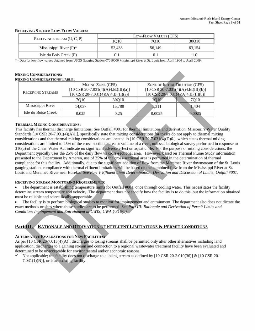
RECEIVING STREAM LOW-FLOW VALUES:
RECEIVING STREAM (U, C, P) LOW-FLOW VALUES (CFS) 1Q10 7Q10 30Q10
Mississippi River (P)* 52,433 56,149 63,154
Isle du Bois Creek (P) 0.1 0.1 1.0 * - Data for low-flow values obtained from USGS Gauging Station 07010000 Mississippi River at St. Louis from April 1964 to April 2009. MIXING CONSIDERATIONS: MIXING CONSIDERATIONS TABLE:
RECEIVING STREAMS
MIXING ZONE (CFS) [10 CSR 20-7.031(4)(A)4.B.(III)(a)] [10 CSR 20-7.031(4)(A)4.B.(II)(a)]
ZONE OF INITIAL DILUTION (CFS) [10 CSR 20-7.031(4)(A)4.B.(III)(b)] [10 CSR 20-7.031(4)(A)4.B.(II)(b)]
7Q10 30Q10 1Q10 7Q10 Mississippi River 14,037 15,788 1,311 1,404
Isle du Boise Creek 0.025 0.25 0.0025 0.0025 THERMAL MIXING CONSIDERATIONS: This facility has thermal discharge limitations. See Outfall #001 for thermal limitations and derivation. Missouri’s Water Quality Standards [10 CSR 20-7.031(4)(A)1.], specifically state that mixing considerations for toxics do not apply to thermal mixing considerations and that thermal mixing considerations are located in [10 CSR 20-7.031(4)(D)6.], which states thermal mixing considerations are limited to 25% of the cross-sectional area or volume of a river, unless a biological survey performed in response to 316(a) of the Clean Water Act indicate no significant adverse effect on aquatic life. For the purpose of mixing considerations, the Department typically uses the 25% of the daily flow vs cross-sectional area. However, based on Thermal Plume Study information presented to the Department by Ameren, use of 25% of the cross-sectional area is permitted in the determination of thermal compliance for this facility. Additionally, due to the significant addition of flow from the Meramec River downstream of the St. Louis gauging station, compliance with thermal effluent limitations will be based on the combined flow from the Mississippi River at St. Louis and Meramec River near Eureka. See Part V Effluent Limit Determination; Derivation and Discussion of Limits; Outfall #001. RECEIVING STREAM MONITORING REQUIREMENTS: • The department is establishing temperature limits for Outfall #001, once through cooling water. This necessitates the facility determine stream temperature and velocity. The department does not specify how the facility is to do this, but the information obtained must be reliable and scientifically supportable. • The facility is to perform biological studies to monitor for impingement and entrainment. The department also does not dictate the exact methods or sites where these studies are to be performed. See Part III: Rationale and Derivation of Permit Limits and Condition; Impingement and Entrainment at CWIS; CWA § 316(b). Part III. RATIONALE AND DERIVATION OF EFFLUENT LIMITATIONS & PERMIT CONDITIONS ALTERNATIVE EVALUATIONS FOR NEW FACILITIES: As per [10 CSR 20-7.015(4)(A)], discharges to losing streams shall be permitted only after other alternatives including land application, discharges to a gaining stream and connection to a regional wastewater treatment facility have been evaluated and determined to be unacceptable for environmental and/or economic reasons. Not applicable; the facility does not discharge to a losing stream as defined by [10 CSR 20-2.010(36)] & [10 CSR 20-
7.031(1)(N)], or is an existing facility.
Ameren Missouri-Rush Island Energy Center Fact Sheet Page 9 of 51
ANTI-BACKSLIDING: Federal Regulations [CWA §303(d)(4); CWA §402(c); 40 CFR Part 122.44(I)] require a reissued permit to be as stringent as the previous permit with some exceptions. Backsliding (a less stringent permit limitation) is only allowed under certain conditions. Limitations in this operating permit for the reissuance conform to the anti-backsliding provisions of Section 402(o) of the Clean
Water Act, and 40 CFR Part 122.44. Information is available which was not available at the time of permit issuance (other than revised regulations, guidance, or
test methods) which would have justified the application of a less stringent effluent limitation. This permits changes WET testing requirements from pass/fail to monitoring only for toxic units. This change reflects
modifications to Missouri’s Effluent Regulation found at 10 CSR 20-7.015. 40 CFR 122.44(d)(1)(ii) requiring the department to establish effluent limitations to control all parameters which have the reasonable potential to cause or contribute to an excursion above any state water quality standard, including state narrative criteria. The previous permit imposed a pass/fail limitation without collecting sufficient numerical data to conduct an analytical reasonable potential analysis. The permit writer has made a reasonable potential analysis/determination which concluded the facility does not currently have reasonable potential but monitoring is required. Implementation of the toxic unit monitoring requirement will allow the department to effect numeric criteria in accordance with water quality standards established under CWA §303.
The Department determined technical mistakes or mistaken interpretations of law were made in issuing the permit under section 402(a)(1)(b). The previous permit contained a specific set of prohibitions related to general criteria found in 10 CSR 20-7.031(4);
however, there was no determination as to whether the discharges have reasonable potential to cause or contribute to excursion of those general water quality standards in the previous permit. Federal regulations 40 CFR 122.44(d)(1)(iii) requires that in instances were reasonable potential (RP) to cause or contribute to an exceedance of a water quality standard exists, a numeric limitation must be included in the permit. Rather than conducting the appropriate RP determination and establishing numeric effluent limitations for specific pollutant parameters, the previous permit simply placed the prohibitions in the permit. These conditions were removed from the permit. Appropriate reasonable potential determinations were conducted for each general criterion listed in 10 CSR 20-7.031(4) and effluent limitations were placed in the permit for those general criteria where it was determined the discharge had reasonable potential to cause or contribute to excursions of the general criteria. Specific effluent limitations were not included for those general criteria where it was determined that the discharges will not cause or contribute to excursions of general criteria. Removal of the prohibitions does not reduce the protections of the permit or allow for impairment of the receiving stream. The permit maintains sufficient effluent limitations, monitoring requirements and best management practices to protect water quality.
ANTIDEGRADATION REVIEW: For process water discharge with new, altered, or expanding discharges, the department is to document, by means of antidegradation review, if the use of a water body’s available assimilative capacity is justified. In accordance with Missouri’s water quality regulations for antidegradation [10 CSR 20-7.031(3)], degradation may be justified by documenting the socio-economic importance of a discharge after determining the necessity of the discharge. Facilities must submit the antidegradation review request to the department prior to establishing, altering, or expanding discharges. See http://dnr.mo.gov/env/wpp/permits/antideg-implementation.htm Not applicable; the facility has not submitted information proposing expanded or altered process water discharge; no further
degradation proposed therefore no further review necessary. The construction of Outfall #01A is to replace the process discharges from Outfall #002 with the proposed construction covered under CP001861. Outfall #01A will become the process wastewater discharge, while Outfall #002 will become intermittent and then stormwater, as the cap is constructed to close the ash ponds. Overall there is an expected reduction in flow as Ameren is converting to a dry handling process for the ash. From the construction application, is the expected discharge concentrations and mass loading from Outfall #01A in comparison to the existing discharge from Outfall#002.
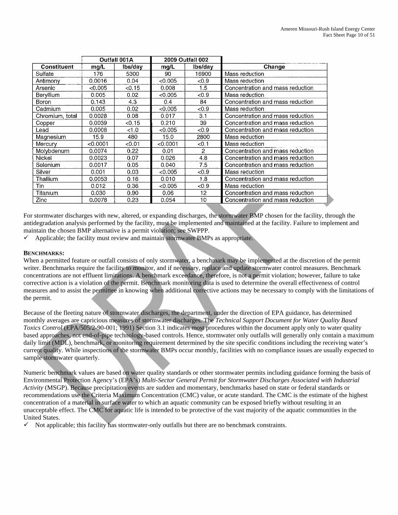
Ameren Missouri-Rush Island Energy Center Fact Sheet Page 10 of 51
For stormwater discharges with new, altered, or expanding discharges, the stormwater BMP chosen for the facility, through the antidegradation analysis performed by the facility, must be implemented and maintained at the facility. Failure to implement and maintain the chosen BMP alternative is a permit violation; see SWPPP. Applicable; the facility must review and maintain stormwater BMPs as appropriate. BENCHMARKS: When a permitted feature or outfall consists of only stormwater, a benchmark may be implemented at the discretion of the permit writer. Benchmarks require the facility to monitor, and if necessary, replace and update stormwater control measures. Benchmark concentrations are not effluent limitations. A benchmark exceedance, therefore, is not a permit violation; however, failure to take corrective action is a violation of the permit. Benchmark monitoring data is used to determine the overall effectiveness of control measures and to assist the permittee in knowing when additional corrective actions may be necessary to comply with the limitations of the permit. Because of the fleeting nature of stormwater discharges, the department, under the direction of EPA guidance, has determined monthly averages are capricious measures of stormwater discharges. The Technical Support Document for Water Quality Based Toxics Control (EPA/505/2-90-001; 1991) Section 3.1 indicates most procedures within the document apply only to water quality based approaches, not end-of-pipe technology-based controls. Hence, stormwater only outfalls will generally only contain a maximum daily limit (MDL), benchmark, or monitoring requirement determined by the site specific conditions including the receiving water’s current quality. While inspections of the stormwater BMPs occur monthly, facilities with no compliance issues are usually expected to sample stormwater quarterly. Numeric benchmark values are based on water quality standards or other stormwater permits including guidance forming the basis of Environmental Protection Agency’s (EPA’s) Multi-Sector General Permit for Stormwater Discharges Associated with Industrial Activity (MSGP). Because precipitation events are sudden and momentary, benchmarks based on state or federal standards or recommendations use the Criteria Maximum Concentration (CMC) value, or acute standard. The CMC is the estimate of the highest concentration of a material in surface water to which an aquatic community can be exposed briefly without resulting in an unacceptable effect. The CMC for aquatic life is intended to be protective of the vast majority of the aquatic communities in the United States. Not applicable; this facility has stormwater-only outfalls but there are no benchmark constraints.
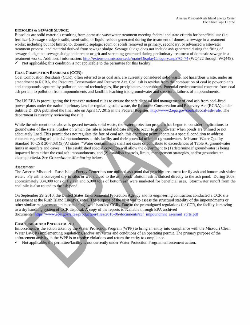
Ameren Missouri-Rush Island Energy Center Fact Sheet Page 11 of 51
BIOSOLIDS & SEWAGE SLUDGE: Biosolids are solid materials resulting from domestic wastewater treatment meeting federal and state criteria for beneficial use (i.e. fertilizer). Sewage sludge is solid, semi-solid, or liquid residue generated during the treatment of domestic sewage in a treatment works; including but not limited to, domestic septage; scum or solids removed in primary, secondary, or advanced wastewater treatment process; and material derived from sewage sludge. Sewage sludge does not include ash generated during the firing of sewage sludge in a sewage sludge incinerator or grit and screening generated during preliminary treatment of domestic sewage in a treatment works. Additional information: http://extension.missouri.edu/main/DisplayCategory.aspx?C=74 (WQ422 through WQ449). Not applicable; this condition is not applicable to the permittee for this facility. COAL COMBUSTION RESIDUALS (CCR): Coal Combustion Residuals (CCR), often referred to as coal ash, are currently considered solid waste, not hazardous waste, under an amendment to RCRA, the Resource Conservation and Recovery Act. Coal ash is residue from the combustion of coal in power plants and compounds captured by pollution control technologies, like precipitators or scrubbers. Potential environmental concerns from coal ash pertain to pollution from impoundments and landfills leaching into groundwater and structural failures of impoundments. The US EPA is promulgating the first-ever national rules to ensure the safe disposal and management of coal ash from coal-fired power plants under the nation’s primary law for regulating solid waste, the Resource Conservation and Recovery Act (RCRA) under Subtitle D. EPA published the final rule on April 17, 2015 in the Federal Register. http://www2.epa.gov/coalash/coal-ash-rule. The department is currently reviewing the rule. While the rule mentioned above is geared towards solid waste, the water protection program has begun to consider implications to groundwater of the state. Studies on which the rule is based indicate impacts occur to groundwater when ponds are unlined or not adequately lined. This permit does not regulate the fate of coal ash, this operating permit contains a special condition to address concerns regarding ash ponds/impoundments at this facility and their potential to impact groundwater. Missouri Water Quality Standard 10 CSR 20-7.031(5)(A) states, “Water contaminants shall not cause or contribute to exceedances of Table A, groundwater limits in aquifers and caves...” The established special condition will allow the department to (1) determine if groundwater is being impacted from either the coal ash impoundments, and (2) establish controls, limits, management strategies, and/or groundwater cleanup criteria. See Groundwater Monitoring below. Assessment: The Ameren Missouri – Rush Island Energy Center has one unlined ash pond that provides treatment for fly ash and bottom ash sluice water. Fly ash is conveyed dry to silos or wet sluiced to the ash pond. Bottom ash is sluiced directly to the ash pond. During 2008, approximately 334,000 tons of fly ash and 6,000 tons of bottom ash were marketed for beneficial uses. Stormwater runoff from the coal pile is also routed to the ash pond. On September 29, 2010, the United States Environmental Protection Agency and its engineering contractors conducted a CCR site assessment at the Rush Island Energy Center. The purpose of the visit was to assess the structural stability of the impoundments or other similar management units containing “wet” handled CCRs. Due to the promulgated regulations for CCR, the facility is moving to a dry handling system of CCR disposal. A copy of the reports is available through EPA archived documents: https://www.epa.gov/sites/production/files/2016-06/documents/ccr_impoundmnt_asesmnt_rprts.pdf COMPLIANCE AND ENFORCEMENT: Enforcement is the action taken by the Water Protection Program (WPP) to bring an entity into compliance with the Missouri Clean Water Law, its implementing regulations, and/or any terms and conditions of an operating permit. The primary purpose of the enforcement activity in the WPP is to resolve violations and return the entity to compliance. Not applicable; the permittee/facility is not currently under Water Protection Program enforcement action.
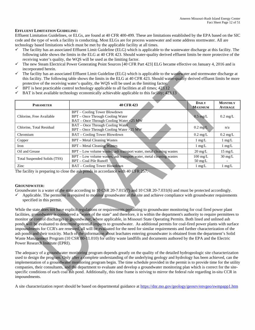
Ameren Missouri-Rush Island Energy Center Fact Sheet Page 12 of 51
EFFLUENT LIMITATION GUIDELINE: Effluent Limitation Guidelines, or ELGs, are found at 40 CFR 400-499. These are limitations established by the EPA based on the SIC code and the type of work a facility is conducting. Most ELGs are for process wastewater and some address stormwater. All are technology based limitations which must be met by the applicable facility at all times. The facility has an associated Effluent Limit Guideline (ELG) which is applicable to the wastewater discharge at this facility. The
following table shows the limits in the ELG at 40 CFR 423. Should water-quality derived effluent limits be more protective of the receiving water’s quality, the WQS will be used as the limiting factor.
The new Steam Electrical Power Generating Point Sources [40 CFR Part 423] ELG became effective on January 4, 2016 and is incorporated herein.
The facility has an associated Effluent Limit Guideline (ELG) which is applicable to the wastewater and stormwater discharge at this facility. The following table shows the limits in the ELG at 40 CFR 423. Should water-quality derived effluent limits be more protective of the receiving water’s quality, the WQS will be used as the limiting factor.
BPT is best practicable control technology applicable to all facilities at all times; 423.12 BAT is best available technology economically achievable applicable to this facility; 423.13
PARAMETER 40 CFR 423 DAILY MAXIMUM
MONTHLY AVERAGE
Chlorine, Free Available BPT – Cooling Tower Blowdown BPT – Once Through Cooling Water BAT – Once Through Cooling Water <25 MW
0.5 mg/L 0.2 mg/L
Chlorine, Total Residual BAT – Once Through Cooling Water BPT – Once Through Cooling Water >25 MW 0.2 mg/L n/a
Chromium BAT – Cooling Tower Blowdown 0.2 mg/L 0.2 mg/L Copper BPT – Metal Cleaning Wastes 1 mg/L 1 mg/L Iron BPT – Metal Cleaning Wastes 1 mg/L 1 mg/L Oil and Grease BPT – Low volume wastes, ash transport water, metal cleaning wastes 20 mg/L 15 mg/L
Total Suspended Solids (TSS) BPT – Low volume wastes, ash transport water, metal cleaning wastes BPT – Coal Pile Runoff
100 mg/L 50 mg/L
30 mg/L -
Zinc BAT – Cooling Tower Blowdown 1 mg/L 1 mg/L The facility is preparing to close the ash ponds in accordance with 40 CFR 257. GROUNDWATER: Groundwater is a water of the state according to 10 CSR 20-7.015(7) and 10 CSR 20-7.031(6) and must be protected accordingly. Applicable. The permittee is required to monitor groundwater at the site and achieve compliance with groundwater requirements
specified in this permit.
While the state does not have explicit regulations or requirements pertaining to groundwater monitoring for coal fired power plant facilities, groundwater is considered a "water of the state" and therefore, it is within the department's authority to require permittees to monitor or control discharges to groundwater, where applicable, in Missouri State Operating Permits. Both lined and unlined ash ponds will be evaluated to determine potential impacts to groundwater. As additional permits for coal-fired power plants with surface impoundments for CCR's are renewed, all will be evaluated for the need for similar requirements and further characterization of the ash ponds and their toxicity. Much of the information about leachates entering groundwater is obtained from the department’s Solid Waste Management Program (10 CSR 80-11.010) for utility waste landfills and documents authored by the EPA and the Electric Power Research Institute (EPRI). The adequacy of a groundwater monitoring program depends greatly on the quality of the detailed hydrogeologic site characterization used to design the program. Only after a complete understanding of the underlying geology and hydrology has been achieved, can the implementation of a groundwater monitoring program begin. The time schedule provided in the permit is to provide time for the utility companies, their consultants, and the department to evaluate and develop a groundwater monitoring plan which is correct for the site-specific conditions of each coal ash pond. Additionally, this time frame is striving to mirror the federal rule regarding in-situ CCR in impoundments. A site characterization report should be based on departmental guidance at https://dnr.mo.gov/geology/geosrv/envgeo/swmpapp1.htm
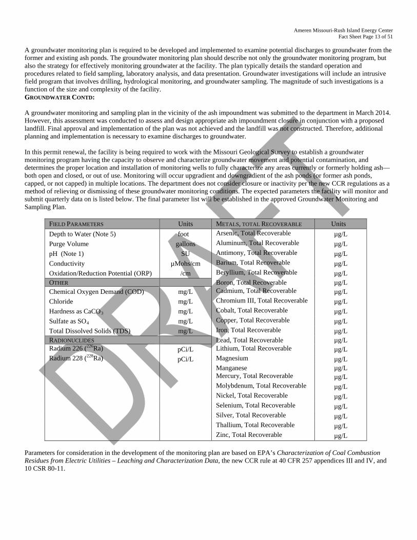
Ameren Missouri-Rush Island Energy Center Fact Sheet Page 13 of 51
A groundwater monitoring plan is required to be developed and implemented to examine potential discharges to groundwater from the former and existing ash ponds. The groundwater monitoring plan should describe not only the groundwater monitoring program, but also the strategy for effectively monitoring groundwater at the facility. The plan typically details the standard operation and procedures related to field sampling, laboratory analysis, and data presentation. Groundwater investigations will include an intrusive field program that involves drilling, hydrological monitoring, and groundwater sampling. The magnitude of such investigations is a function of the size and complexity of the facility. GROUNDWATER CONTD: A groundwater monitoring and sampling plan in the vicinity of the ash impoundment was submitted to the department in March 2014. However, this assessment was conducted to assess and design appropriate ash impoundment closure in conjunction with a proposed landfill. Final approval and implementation of the plan was not achieved and the landfill was not constructed. Therefore, additional planning and implementation is necessary to examine discharges to groundwater. In this permit renewal, the facility is being required to work with the Missouri Geological Survey to establish a groundwater monitoring program having the capacity to observe and characterize groundwater movement and potential contamination, and determines the proper location and installation of monitoring wells to fully characterize any areas currently or formerly holding ash—both open and closed, or out of use. Monitoring will occur upgradient and downgradient of the ash ponds (or former ash ponds, capped, or not capped) in multiple locations. The department does not consider closure or inactivity per the new CCR regulations as a method of relieving or dismissing of these groundwater monitoring conditions. The expected parameters the facility will monitor and submit quarterly data on is listed below. The final parameter list will be established in the approved Groundwater Monitoring and Sampling Plan.
FIELD PARAMETERS Units METALS, TOTAL RECOVERABLE Units Depth to Water (Note 5) foot Arsenic, Total Recoverable µg/L Purge Volume gallons Aluminum, Total Recoverable µg/L pH (Note 1) SU Antimony, Total Recoverable µg/L Conductivity µMohs/cm Barium, Total Recoverable µg/L Oxidation/Reduction Potential (ORP) /cm Beryllium, Total Recoverable µg/L OTHER Boron, Total Recoverable µg/L Chemical Oxygen Demand (COD) mg/L Cadmium, Total Recoverable µg/L Chloride mg/L Chromium III, Total Recoverable µg/L Hardness as CaCO3 mg/L Cobalt, Total Recoverable µg/L Sulfate as SO4 mg/L Copper, Total Recoverable µg/L Total Dissolved Solids (TDS) mg/L Iron, Total Recoverable µg/L RADIONUCLIDES Lead, Total Recoverable µg/L Radium 226 (226Ra) pCi/L Lithium, Total Recoverable µg/L Radium 228 (228Ra) pCi/L Magnesium µg/L Manganese µg/L Mercury, Total Recoverable µg/L Molybdenum, Total Recoverable µg/L Nickel, Total Recoverable µg/L Selenium, Total Recoverable µg/L Silver, Total Recoverable µg/L Thallium, Total Recoverable µg/L Zinc, Total Recoverable µg/L
Parameters for consideration in the development of the monitoring plan are based on EPA’s Characterization of Coal Combustion Residues from Electric Utilities – Leaching and Characterization Data, the new CCR rule at 40 CFR 257 appendices III and IV, and 10 CSR 80-11.
Ameren Missouri-Rush Island Energy Center Fact Sheet Page 14 of 51
This permit is to comply with the requirements in RSMo 644.143 and to establish a long term approach and stewardship of the site and the beneficial uses of the groundwater on this site. 40 CFR 257 is a self-implementing rule and covered under RCRA; this permit does not implement the federal CCR rule. This permit does not shield a facility from the CCR requirements. Compliance with the terms and conditions of this permit identical to or more stringent than the requirements in the federal CCR rule may constitute compliance with the federal CCR rule although not guaranteed. The department realizes there are two different timelines associated with this permit for groundwater monitoring. One is driven solely by the effective date of 40 CFR 257, where the permittee will publish the results from eight statistically independent groundwater samples accurately representing background water quality and the quality of the groundwater surrounding the ash ponds pursuant to 40 CFR 257.93. The other is solely water protection program requirements and the permittee will be required to report that data to the water protection program. While the two have different dates and reporting requirements, the department will allow, if appropriate, the same monitoring well network and quarterly sampling data to be used for the two different requirements. All investigations and reports for the water protection program must be approved by the water protection program and Missouri Geological Survey. Any data gathered by the facility prior to WPP approval may or may not be acknowledged as appropriate monitoring. Data and submittals driven by 40 CFR 257 are not approved by the water protection program. Groundwater Limits and Schedule of Compliance Based on existing groundwater samples at the facility, the department has determined that discharges to groundwater from the ash ponds have potential to cause or contribute to exceedances of the groundwater criteria for arsenic, boron, iron, and manganese. Two compliance options are contained in this permit, listed in Special Condition 21. Groundwater is a water of the state and not, by definition, a water of the United States and therefore a schedule of compliance (SOC) for groundwater is instituted in this permit under the authority of 10 CSR 20-6.010(7), to achieve compliance as soon as practicable. The permittee will need time to evaluate existing characterization of the site and upgrade or implement groundwater monitoring at the facility. Also, the ash pond is planned for closure under the authority of 40 CFR 257 which may influence characteristics of the groundwater at the facility. The schedule is afforded to allow planning and construction of engineering controls to mitigate groundwater discharges from the facility. Should alternate effluent limits be appropriately demonstrated in accordance with 10 CSR 20-7.015(7)(F) this permit will be modified to incorporate alternate effluent limitations for arsenic, boron, iron, and manganese. As groundwater is not a water of the United States by definition, the institution of less stringent permit limitation for groundwater are not subject to federal anti-backsliding provisions [CWA §303(d)(4); CWA §402(c); 40 CFR Part 122.44(I)]. Further, the institution of less stringent permit limitations, or alternate effluent limitations, is in accordance with Missouri’s Water Quality Standards [10 CSR 20-7.031(6)(D)]. IMPINGEMENT AND ENTRAINMENT AT CWIS; CWA § 316(B): The Clean Water Act (CWA) Section 316(b) provides for protection of aquatic life from cooling water intake structures (CWIS) where the facility withdraws more than 2 MGD. Rush Island Energy Center can withdraw over 125 MGD of water from the Mississippi River therefore is subject to all impingement and entrainment studies and reviews as promulgated in 40 CFR 122.21(r) et seq. and 40 CFR Subpart J. The facility is expected to submit all new studies and required information with the application materials six months prior to expiration of the permit. The facility should refer to https://www.epa.gov/sites/production/files/2015-04/documents/cooling-water_esa-instructional-memo_12-11-2014.pdf for additional information. COOLING WATER INTAKE STRUCTURE REQUIREMENTS: The Ameren Missouri – Rush Island Energy Center is equipped with a once-through condenser cooling system. Water is drawn in through an intake structure located 100 feet from the shoreline in the Mississippi River. The face of the intake is parallel to the river flow and is located at the edge of the main channel. This configuration avoids shallow main channel border habitat where fish populations tend to be most concentrated. At “normal” Mississippi River elevation, the intake is designed to withdraw a maximum of approximately 953 MGD. Under normal flow conditions, these structures are under water. The intake structure is divided into four (4) cells, each with its own traveling screens and pump. Within each forebay are two screenwells which each contain a 10-foot wide vertical conventional traveling screen for a total of eight traveling screens for the entire intake structure. There is an 11.25 foot wide by 31.5 foot high opening to each screenwell. At the face of each forebay is a steel trash rack made of bars with 3.5 inch clear openings. Debris and fish on the screens are collected in troughs running along the front and backs of the screens. The troughs lead to an inclined pipe which discharges to the river. Additionally, a system of gates is incorporated into the walls of the screenwells to allow fish to escape the intake.
Ameren Missouri-Rush Island Energy Center Fact Sheet Page 15 of 51
The traveling screens have 3/8 inch woven wire mesh with screenwash operation and rotation based on either manual timer settings or differential pressure across the screen (which is affected by debris loading).In addition to returning fish and debris back to the source waterbody, the Rush Island Energy Center intake structure also incorporates a fish bypass system. FISH BYPASS SYSTEM: An impingement study was conducted in 2006-2007 to satisfy the EPA Phase I Section 316(b) Existing Facilities Rule. The study concluded that nearly 91% of the organisms collected were gizzard shad, threadfin shad and drum. These findings are similar to those found in the 1977-78 study, which concluded that 99% of the organisms collected were gizzard shad and drum. The Department approved the Rush Island Plant 316(b) report on January 11, 1980, determining that the intake structure reflected the “best technology available.” This system consists of a series of open bypass gates located on the screen bay divider walls in front of the traveling water screens. Fish that enter the intake structure can swim through these gates to an exit located in the downstream wall of the structure. Each of the bypass gates are 6.7 feet wide and 21.6 feet high and centered in the screenwell opening with an invert at EL 346.0 feet (approximately 6.5 feet above the intake structure floor) and top at EL 368.0 feet. As a result of the intake structure design, the velocity in the screen bay is 0.52 feet/second at normal Mississippi River elevation. There have been no significant physical changes to the intake pumps, traveling screens or other relevant components since that time. The facility requests renewal of BTA approval under Section 316(b). OPERATIONAL OPTIMIZATION: There is the capacity for potentially minor design and operational changes which would optimize the current technology and could reduce impingement mortality that the Ameren should evaluate and implement, if found to be effective. These design and operational changes may include the following: • Recirculate warm water to the intake structure only when necessary to prevent ice formation. • Scheduled plant outages should be timed to the extent possible to coincide with periods of greatest impingement. • Operate screens continuously and at high speed during periods when impingement is greatest. • Shape fish buckets or baskets to minimize hydrodynamic turbulence within the bucket or basket. Use smooth-woven screen mesh in
the buckets or baskets to minimize descaling. • Evaluate whether the high pressure and low pressure washes can be operated at lower pressures to reduce damage and stress to fish
while not interfering with plant operations. • Optimize location of screen wash sprays to provide a more gentle fish transfer from screen to fish return trough. • Minimize turbulence in the fish return system. NEW 316(b) REQUIREMENTS: To meet the newly promulgated CWA §316(b) requirements, the facility will be required to meet one of the identified impingement BTA technologies, however as the facility withdraws more than 125 MGD for cooling water needs, will also need to address entrainment. The implementation of impingement technology is delayed until the required entrainment studies are complete. The applicability can be found in 40 CFR 122.21 (r)(1) studies include: a. Source Water Physical Data Report : 40 CFR 122.21(r)(2) This report requires a description and scaled drawings showing the
physical configuration of the water body, including areal dimensions, depths, and temperature regimes, identification and characterization of the source waterbody’s hydrological and geomorphological features, estimate the intake’s area of influence within the waterbody and locational maps.
b. Cooling Water Intake Structure Data Report, 40 CFR 122.21(r)(3): This report requires information on the design of the intake structure and its location in the water column. It includes design intake flows, daily hours of operation, number of days of the year in operation and seasonal changes, if applicable; a flow distribution and water balance diagram that includes all sources of water to the facility, recirculating flows, and discharges, and engineering drawings of the cooling water intake structure.
c. Source Water Baseline Biological Characterization Data Report, 40 CFR 122.21(r)(4): This report characterizes the biological community in the vicinity of the cooling water intake structure.
d. Cooling Water System Data Report, 40 CFR 122.21(r)(5): This report provides information on the operation of the cooling water system including descriptions of reductions in water withdrawals, recycled water, proportion of the source waterbody withdrawn.
e. Chosen Method of Compliance with Impingement Mortality Standard, 40 CFR 122.21(r)(6). Ameren must identify their chosen compliance method and if applicant chooses to comply with a technology option that requires the Impingement Technology Optimization Study, the study must be submitted.
f. Performance Studies, 40 CFR 122.21(r)(7): This rule section requires a summary of biological survival studies conducted at the facility and a summary of any conclusions or results, including; site-specific studies addressing technology efficacy, entrainment survival, and other impingement and entrainment mortality studies. If using data more than 10 years old, applicant must explain why the data is still relevant and representative.
g. Operational Status, 40 CFR 122.21(r)(8): The operational status report includes descriptions of each unit’s operating status including age of the unit, capacity utilization for the previous 5 years, and any major upgrades completed within the last 15 years, including boiler replacement, condenser replacement, turbine replacement, and fuel change.
Ameren Missouri-Rush Island Energy Center Fact Sheet Page 16 of 51
h. Entrainment Characterization Study, 40 CFR 122.21(r)(9):Facilities that withdraw 125 MGD or more must develop for
submission to the Director that includes 2 years of entrainment data. Entrainment Data Collection Method must identify and document the data collection period and frequency; identify all organisms collected to lowest taxon possible of all life stages of fish that are in the vicinity of the intake structure; identify threatened or endangered species, identify and document how the location of the intake structure in the waterbody are accounted for in data collection. The Biological Entrainment Characterization must describe all life stages including a description of their abundance and their temporal and spatial characteristics in the vicinity of the intake structure, based on sufficient data to characterize annual, seasonal, and diel variation in entrainment including variations related to climate, weather difference, feeding, and water column migration; may include historical data that is representative of the current operation of the facility; identification of all life stages of fish must represent both motile and non-motile life stages Analysis and Support Documentation of current entrainment of all life stages, may include historical data that is representative of current operation of the facility and of biological conditions at the site. Data to support the calculations must be collected during period of representative operational flows and flows associated with data collection must be documented. The method for determining latent mortality along with specific organism mortality or survival must be identified; the facility must identify and document all assumptions and calculation to determine total entrainment, along with all methods and QA/QC procedures.
i. Comprehensive Technical Feasibility and Cost Evaluation Study, 40 CFR 122.21(r)(10): Facilities that withdraw 125 MGD or more must develop for submission an engineering study of the technical feasibility and costs of entrainment technology options. Technical Feasibility must include closed cycle recirculation discussion, fine mesh screens with mesh size of 2 mm or smaller, water reuse or alternate sources of cooling water; description of all technologies and operational measures considered; land availability, including evaluation of adjacent and acres potentially available due to generating unit retirements, potential repurposing of areas devoted to ponds, coal piles, rail yards, transmission yards, and parking lots; discussion of available sources of process water, grey water, wastewater, reclaimed water or other waters of appropriate quantity and quality; and documentation of factors other than cost that may make a candidate technology impractical or infeasible. The cost evaluations must include estimates for all technologies considered; must be adjusted to estimate social costs; all costs must be represented in net present value and annual value; cost clearly labeled as compliance or social costs; separately discuss facility level costs and social costs; compliance costs are calculated after-tax, include administrative costs, permit costs, any outages, downtime; and social costs adjustment includes Director’s administrative cost.
j. Benefits Valuation Study, 40 CFR 122.21(r)(11): Facilities withdrawing 125 MGD or more must develop an evaluation of the entrainment technology and operational measure benefits. Each category of benefit must be described narratively and benefits should be quantified in physical or biological units and monetized using appropriate economic valuation methods. Must use the Entrainment Characterization Study. Benefit Valuation Study must include: incremental changes in number of individual fish lost due to impingement mortality and entrainment for all life stages; description of basis for any estimates of changes in the stock size or harvest levels of commercial and recreational fish; description of basis for any monetized values assigned to changes in the stock size of commercial and recreational fish, and to any other ecosystem or non-use benefits; discussion of mitigation efforts completed before October 2014; discussion with quantification and monetization, where possible any other benefits expected to accrue, including improvements for mammals, birds, other organisms and aquatic habitats; and discussion of benefits expected to result from reductions in thermal discharges from entrainment technologies (closed-cycle cooling).
k. Non-Water Quality Impacts Assessment, 40 CFR 122.21(r)(12): Facilities that withdraw 125 MGD or more must develop for submission to the Director a detailed site-specific discussion of changes in non-water quality environmental and other impacts attributed to each technology and operational measure, both increases and decreases. Must include discussion of estimate in change in energy consumption, estimate of air pollutant emissions and of human health environmental impacts, estimates in change in noise, discussion of impacts to safety, including potential plumes, icing and availability of emergency cooling water, discussion of facility reliability, impacts to production based on process unit, reliability due to cooling water availability; significant changes in consumption of water, including comparison of evaporative losses of both once through and closed cycle recirculation, documentation of impacts attributable to changes in water consumption, and discussion of all attempts to mitigate each of these factors.
l. Additional measures to protect federally listed threatened and endangered species and designated critical habitat, 40 CFR 125.94(g). The Director may establish additional permit control measures, monitoring requirements, reporting requirements than the minimum established to minimize incidental take, reduce or remove detrimental effects, or such control measures may include measures identified by the US Fish and Wildlife Field Office during their 60 day review. When the Director requires additional measures for federally listed species, monitoring is required, 40 CFR 125.96(g) and may require additional studies and monitoring if threatened or endangered species identified in the vicinity of the intake, 40 CFR 125.98(d).
m. Peer Review, 40 CFR 122.21(r)(13): The Non-Water Quality Impacts Assessment, Benefits Valuation Study, and Comprehensive Technical Feasibility and Cost Evaluation Study require peer review. Facility must submit the studies for external peer review. Facility selects the peer reviewers and must notify the Department in advance of the peer review. The Director can disapprove a peer reviewer or require additional peer reviewers. The Director may confer with EPA, US Fish and Wildlife, MDC, and PSC to determine which peer review comments must be addressed. Ameren must provide an explanation for any significant reviewer comment not accepted.
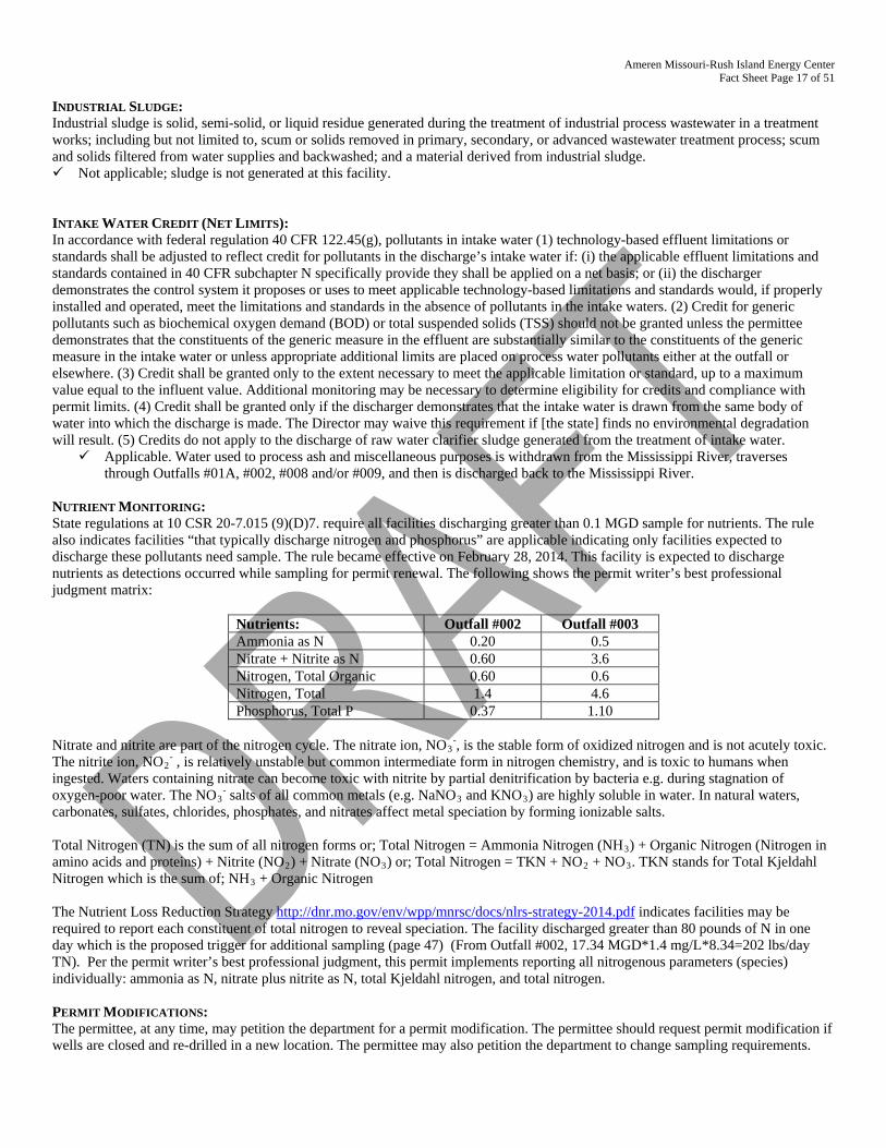
Ameren Missouri-Rush Island Energy Center Fact Sheet Page 17 of 51
INDUSTRIAL SLUDGE: Industrial sludge is solid, semi-solid, or liquid residue generated during the treatment of industrial process wastewater in a treatment works; including but not limited to, scum or solids removed in primary, secondary, or advanced wastewater treatment process; scum and solids filtered from water supplies and backwashed; and a material derived from industrial sludge. Not applicable; sludge is not generated at this facility. INTAKE WATER CREDIT (NET LIMITS): In accordance with federal regulation 40 CFR 122.45(g), pollutants in intake water (1) technology-based effluent limitations or standards shall be adjusted to reflect credit for pollutants in the discharge’s intake water if: (i) the applicable effluent limitations and standards contained in 40 CFR subchapter N specifically provide they shall be applied on a net basis; or (ii) the discharger demonstrates the control system it proposes or uses to meet applicable technology-based limitations and standards would, if properly installed and operated, meet the limitations and standards in the absence of pollutants in the intake waters. (2) Credit for generic pollutants such as biochemical oxygen demand (BOD) or total suspended solids (TSS) should not be granted unless the permittee demonstrates that the constituents of the generic measure in the effluent are substantially similar to the constituents of the generic measure in the intake water or unless appropriate additional limits are placed on process water pollutants either at the outfall or elsewhere. (3) Credit shall be granted only to the extent necessary to meet the applicable limitation or standard, up to a maximum value equal to the influent value. Additional monitoring may be necessary to determine eligibility for credits and compliance with permit limits. (4) Credit shall be granted only if the discharger demonstrates that the intake water is drawn from the same body of water into which the discharge is made. The Director may waive this requirement if [the state] finds no environmental degradation will result. (5) Credits do not apply to the discharge of raw water clarifier sludge generated from the treatment of intake water.
Applicable. Water used to process ash and miscellaneous purposes is withdrawn from the Mississippi River, traverses through Outfalls #01A, #002, #008 and/or #009, and then is discharged back to the Mississippi River.
NUTRIENT MONITORING: State regulations at 10 CSR 20-7.015 (9)(D)7. require all facilities discharging greater than 0.1 MGD sample for nutrients. The rule also indicates facilities “that typically discharge nitrogen and phosphorus” are applicable indicating only facilities expected to discharge these pollutants need sample. The rule became effective on February 28, 2014. This facility is expected to discharge nutrients as detections occurred while sampling for permit renewal. The following shows the permit writer’s best professional judgment matrix:
Nutrients: Outfall #002 Outfall #003 Ammonia as N 0.20 0.5 Nitrate + Nitrite as N 0.60 3.6 Nitrogen, Total Organic 0.60 0.6 Nitrogen, Total 1.4 4.6 Phosphorus, Total P 0.37 1.10
Nitrate and nitrite are part of the nitrogen cycle. The nitrate ion, NO3
-, is the stable form of oxidized nitrogen and is not acutely toxic. The nitrite ion, NO2
- , is relatively unstable but common intermediate form in nitrogen chemistry, and is toxic to humans when ingested. Waters containing nitrate can become toxic with nitrite by partial denitrification by bacteria e.g. during stagnation of oxygen-poor water. The NO3
- salts of all common metals (e.g. NaNO3 and KNO3) are highly soluble in water. In natural waters, carbonates, sulfates, chlorides, phosphates, and nitrates affect metal speciation by forming ionizable salts. Total Nitrogen (TN) is the sum of all nitrogen forms or; Total Nitrogen = Ammonia Nitrogen (NH3) + Organic Nitrogen (Nitrogen in amino acids and proteins) + Nitrite (NO2) + Nitrate (NO3) or; Total Nitrogen = TKN + NO2 + NO3. TKN stands for Total Kjeldahl Nitrogen which is the sum of; NH3 + Organic Nitrogen The Nutrient Loss Reduction Strategy http://dnr.mo.gov/env/wpp/mnrsc/docs/nlrs-strategy-2014.pdf indicates facilities may be required to report each constituent of total nitrogen to reveal speciation. The facility discharged greater than 80 pounds of N in one day which is the proposed trigger for additional sampling (page 47) (From Outfall #002, 17.34 MGD*1.4 mg/L*8.34=202 lbs/day TN). Per the permit writer’s best professional judgment, this permit implements reporting all nitrogenous parameters (species) individually: ammonia as N, nitrate plus nitrite as N, total Kjeldahl nitrogen, and total nitrogen.
PERMIT MODIFICATIONS: The permittee, at any time, may petition the department for a permit modification. The permittee should request permit modification if wells are closed and re-drilled in a new location. The permittee may also petition the department to change sampling requirements.
Ameren Missouri-Rush Island Energy Center Fact Sheet Page 18 of 51
REASONABLE POTENTIAL ANALYSIS (RPA): Federal regulation [40 CFR Part 122.44(d)(1)(i)] requires effluent limitations for all pollutants that are (or may be) discharged at a level causing or have the reasonable potential to cause (or contribute to) an in-stream excursion above narrative or numeric water quality standards. If the permit writer determines any give pollutant has the reasonable potential to cause or contribute to an in-stream excursion above the WQS, the permit must contain effluent limits for that pollutant [40 CFR Part 122.44(d)(1)(iii)]. Not applicable; the Reasonable Potential Analysis typically conducted per (TSD, EPA/505/2-90-001, Section 3.3.2). was not
completed due to the following reasons: • Outfall #001: this outfall pertains to thermal discharge. Temperature data was reviewed for the past five years; however, there
is no TSD method to determine RP for temperature data. The permit writer has determined the facility does have reasonable potential to exceed Mississippi temperature allowances.
• Outfall #002 & #008: ash ponds receive “net” total suspended solids; there is no water quality standard for TSS applicable to this wastestream at this outfall. The ash pond outfalls have been monitoring for sulfates. However, Missouri’s water quality standards are written with the sum of sulfates plus chlorides. No analytical RP was performed; the permit writer used best professional judgment to determine the facility may have RP for sulfates as it is a parameter of concern for the industry. Whole Effluent Toxicity tests were performed once per year at a 10% allowable effluent concentration.. The permit writer has used best professional judgment to determine WET testing is still warranted.
• Outfall #03: This outfall contains technology-based effluent limits, no RPA is warranted. The parameters on this outfall must remain regardless of RP.
• Emergency outfalls #008 & #009: The permit writer has determined the emergency outfalls are non-discharging structures therefore no RP technically exists. However, should these outfalls discharge, certain parameters must be sampled.
• Stormwater outfalls: RP using an analytical RPA for stormwater is not advised because the TSD is for continuously discharging facilities per section 3.1 of EPA/505/2-90-001; not for end-of-pipe technology based controls.
SCHEDULE OF COMPLIANCE (SOC): A schedule of remedial measures included in a permit, including an enforceable sequence of interim requirements (actions, effluent limits, operations, or milestone events) leading to compliance with the Missouri Clean Water Law, its implementing regulations, and/or the terms and conditions of an operating permit. SOCs are allowed under 40 CFR 122.47 providing certain conditions are met. Applicable; the time given for effluent limitations of this permit listed under Interim Effluent Limitation and Final Effluent
Limitations were established in accordance with [10 CSR 20-7.031(12)]. o The facility has been given a 2 year schedule of compliance to meet final effluent limits for temperature at Outfall #001.
Previous permit limits instituted thermal discharge as an internal energy increase and was reported in btu/hr (British Thermal Units). However, Missouri water quality standards are written to consider the temperature of the receiving stream and the actual discharge of the effluent. Temperature is considered a water contaminant per 10 CSR 20-7.031(5)(D) and must be regulated as such.
o For compliance with groundwater standards, the facility is given a 10 year schedule of compliance to attain final limits. The facility needs to conduct additional monitoring around the site to verify the site is properly characterized. Also, as the ash pond is planned for closure, the facility needs time after the cap is installed to verify the concentrations in the groundwater and the potential exposure pathways.
SECONDARY CONTAINMENT STRUCTURES SPECIAL CONDITION: The previous permit’s special conditions required sampling of total petroleum hydrocarbons (TPH) under the decision model to discharge stormwater having a sheen in secondary containment. The special condition has been revised in all permits beginning in 2015 to include oil and grease and BTEX (benzene, toluene, ethylbenzene, and xylene) sampling of the potentially contaminated stormwater in secondary containment. This change was due to 1) no water quality standards for TPH; and 2) there are no approved methods found in 40 CFR 136 for TPH. The facility need only sample for these constituents prior to release when a sheen or petroleum odor is present. SPILL REPORTING: Per 10 CSR 24-3.010, any emergency involving a hazardous substance must be reported to the department’s 24 hour Environmental Emergency Response hotline at (573) 634-2436 at the earliest practicable moment after discovery. The department may require the submittal of a written report detailing measures taken to clean up a spill. These reporting requirements apply whether or not the spill results in chemicals or materials leaving the permitted property or reaching waters of the state. This requirement is in addition to the noncompliance reporting requirement found in Standard Conditions Part I. http://dnr.mo.gov/env/esp/spillbill.htm
Ameren Missouri-Rush Island Energy Center Fact Sheet Page 19 of 51
STORMWATER PERMITTING: A standard mass-balance equation cannot be calculated for stormwater from this facility because the stormwater flow and flow in the receiving stream cannot be determined for conditions on any given day. The amount of stormwater discharged from the facility will vary based on previous rainfall, soil saturation, humidity, detention time, BMPs, surface permeability, etc. Flow in the receiving stream will vary based on climatic conditions, size of watershed, amount of surfaces with reduced permeability (houses, parking lots, and the like) in the watershed, hydrogeology, topography, etc. Decreased permeability increases the flash of the stream. It is likely sufficient rainfall to cause a discharge for four continuous days from a facility will also cause some significant amount of flow in the receiving stream. Chronic WQSs are based on a four-day exposure (except ammonia, which is based on a thirty day exposure). In the event a discharge does occur from this facility for four continuous days, some amount of flow will occur in the receiving stream. This flow will dilute stormwater discharges from a facility. For these reasons, most industrial stormwater facilities have limited potential to cause a violation of chronic water quality standards in the receiving stream. Sufficient rainfall to cause a discharge for one hour or more from a facility would not necessarily cause significant flow in a receiving stream. Acute WQSs are based on a one hour of exposure, and must be protected at all times in unclassified streams, and within mixing zones of class P streams [10 CSR 20-7.031(4) and (5)(4)4.B.]. Therefore, industrial stormwater facilities with toxic contaminants do have the potential to cause a violation of acute WQSs if those toxic contaminants occur in sufficient amounts. It is due to the items stated above staff are unable to perform statistical Reasonable Potential Analysis (RPA). However, staff will use their best professional judgment in determining if a facility has a potential to violate Missouri’s Water Quality Standards. STORMWATER POLLUTION PREVENTION PLAN (SWPPP): In accordance with 40 CFR 122.44(k), Best Management Practices (BMPs) must be used to control or abate the discharge of pollutants when: 1) Authorized under section 304(e) of the Clean Water Act (CWA) for the control of toxic pollutants and hazardous substances from ancillary industrial activities; 2) Authorized under section 402(p) of the CWA for the control of stormwater discharges; 3) Numeric effluent limitations are infeasible; or 4) the practices are reasonably necessary to achieve effluent limitations and standards or to carry out the purposes and intent of the CWA. In accordance with the EPA’s Developing Your Stormwater Pollution Prevention Plan, A Guide for Industrial Operators, (Document number EPA 833-B-09-002) [published by the United States Environmental Protection Agency (USEPA) in February 2009], BMPs are measures or practices used to reduce the amount of pollution entering waters of the state from a permitted facility. BMPs may take the form of a process, activity, or physical structure. Additionally in accordance with the Stormwater Management, a SWPPP is a series of steps and activities to 1) identify sources of pollution or contamination, and 2) select and carry out actions which prevent or control the pollution of storm water discharges. A SWPPP must be prepared by the permittee if the SIC code is found in 40 CFR 122.26(b)(14) and/or 10 CSR 20-6.200(2). A SWPPP may be required of other facilities where stormwater has been identified as necessitating better management. The purpose of a SWPPP is to comply with all applicable stormwater regulations by creating an adaptive management plan to control and mitigate stream pollution from stormwater runoff. Developing a SWPPP provides opportunities to employ appropriate BMPs to minimize the risk of pollutants being discharged during storm events. The following paragraph outlines the general steps the permittee should take to determine which BMPs will work to achieve the benchmark values or limits in the permit. This section is not intended to be all encompassing or restrict the use of any physical BMP or operational and maintenance procedure assisting in pollution control. Additional steps or revisions to the SWPPP may be required to meet the requirements of the permit. Areas which should be included in the SWPPP are identified in 40 CFR 122.26(b)(14). Once the potential sources of stormwater pollution have been identified, a plan should be formulated to best control the amount of pollutant being released and discharged by each activity or source. This should include, but is not limited to, minimizing exposure to stormwater, good housekeeping measures, proper facility and equipment maintenance, spill prevention and response, vehicle traffic control, and proper materials handling. Once a plan has been developed the facility will employ the control measures determined to be adequate to achieve the benchmark values discussed above. The facility will conduct monitoring and inspections of the BMPs to ensure they are working properly and re-evaluate any BMP not achieving compliance with permitting requirements. For example, if sample results from an outfall show values of TSS above the benchmark value, the BMP being employed is deficient in controlling stormwater pollution. Corrective action should be taken to repair, improve, or replace the failing BMP. This internal evaluation is required at least once per month but should be continued more frequently if BMPs continue to fail. If failures do occur, continue this trial and error process until appropriate BMPs have been established. For new, altered, or expanded stormwater discharges, the SWPPP shall identify reasonable and effective BMPs while accounting for environmental impacts of varying control methods. The antidegradation analysis must document why no discharge or no exposure options are not feasible. The selection and documentation of appropriate control measures shall serve as an alternative analysis of technology and fulfill the requirements of antidegradation [10 CSR 20-7.031(3)]. For further guidance, consult the antidegradation implementation procedure (http://dnr.mo.gov/env/wpp/docs/AIP050212.pdf).
Ameren Missouri-Rush Island Energy Center Fact Sheet Page 20 of 51
Alternative Analysis (AA) evaluation of the BMPs is a structured evaluation of BMPs that are reasonable and cost effective. The AA evaluation should include practices that are designed to be: 1) non-degrading; 2) less degrading; or 3) degrading water quality. The glossary of AIP defines these three terms. The chosen BMP will be the most reasonable and effective management strategy while ensuring the highest statutory and regulatory requirements are achieved and the highest quality water attainable for the facility is discharged. The AA evaluation must demonstrate why “no discharge” or “no exposure” is not a feasible alternative at the facility. This structured analysis of BMPs serves as the antidegradation review, fulfilling the requirements of 10 CSR 20-7.031(3) Water Quality Standards and Antidegradation Implementation Procedure (AIP), Section II.B. If parameter-specific numeric exceedances continue to occur and the permittee feels there are no practicable or cost-effective BMPs which will sufficiently reduce a pollutant concentration in the discharge to the benchmark values established in the permit, the permittee can submit a request to re-evaluate the benchmark values. This request needs to include 1) a detailed explanation of why the facility is unable to comply with the permit conditions and unable to establish BMPs to achieve the benchmark values; 2) financial data of the company and documentation of cost associated with BMPs for review and 3) the SWPPP, which should contain adequate documentation of BMPs employed, failed BMPs, corrective actions, and all other required information. This will allow the department to conduct a cost analysis on control measures and actions taken by the facility to determine cost-effectiveness of BMPs. The request shall be submitted in the form of an operating permit modification; the application is found at: http://dnr.mo.gov/forms/index.html. Applicable; a SWPPP shall be developed and implemented for this facility. 316(A) THERMAL DISCHARGES Section 316(a) of the Clean Water Act (CWA) applies to point sources with thermal discharges. It authorizes the NPDES permitting authority to impose alternative effluent limitations for the control of the thermal component of a discharge in lieu of the effluent limits that would otherwise be required under section 301 or 306 of the CWA. Regulations implementing section 316(a) are codified at 40 CFR Part 125, subpart H. These regulations identify the criteria and process for determining whether an alternative effluent limitation (i.e., thermal variance from the otherwise applicable effluent limit) may be included in a permit. This means that before a thermal variance can be granted, 40 CFR Parts 125.72 and 125.73 require the permittee to demonstrate that the protection and propagation of the waterbody’s balanced, indigenous population (BIP) of shellfish, fish, and wildlife is being attained. Not Applicable; Rush Island Energy Center does not operate under a thermal variance. Rush Island Energy Center previously
operated with a heat rejection limit and in this permit renewal has a schedule of compliance to report compliance with the Water Quality Standard and the monthly effluent limits for the Mississippi River.
TECHNOLOGY-BASED EFFLUENT LIMITATIONS (TBEL): One of the major strategies of the Clean Water Act (CWA) in making “reasonable further progress toward the national goal of eliminating the discharge of all pollutants” is to require effluent limitations based on the capabilities of the technologies available to control those discharges. Technology-based effluent limitations (TBELs) aim to prevent pollution by requiring a minimum level of effluent quality attainable using demonstrated technologies for reducing discharges of pollutants or pollution into the waters of the United States. TBELs are developed independently of the potential impact of a discharge on the receiving water, which is addressed through water quality standards and water quality-based effluent limitations (WQBELs). The NPDES regulations at Title 40 of the Code of Federal Regulations (CFR) 125.3(a) require NPDES permit writers to develop technology-based treatment requirements, consistent with CWA § 301(b) and § 402(a)(1), represent the minimum level of control that must be imposed in a permit. The regulation also indicates that permit writers must include in permits additional or more stringent effluent limitations and conditions, including those necessary to protect water quality. Regardless of the technology chosen to be the basis for limitations, the facility is not required to install the technology, only to meet the established TBEL. Case-by-case TBELs are developed pursuant to CWA section 402(a)(1), which authorizes the administrator to issue a permit meeting either, 1) all applicable requirements developed under the authority of other sections of the CWA (e.g., technology-based treatment standards, water quality standards) or, 2) before taking the necessary implementing actions related to those requirements, “such conditions as the administrator determines are necessary to carry out the provisions of this Act.” The regulation at §125.3(c)(2) specifically cite this section of the CWA, stating technology-based treatment requirements may be imposed in a permit “on a case-by-case basis under section 402(a)(1) of the Act, to the extent that EPA-promulgated effluent limitations are inapplicable.” Further, §125.3(c)(3) indicates “where promulgated effluent limitations guidelines only apply to certain aspects of the discharger’s operation, or to certain pollutants, other aspects or activities are subject to regulation on a case-by-case basis to carry out the provisions of the act.” When establishing case-by-case effluent limitations using best professional judgment, the permit writer should cite in the fact sheet or statement of basis both the approach used to develop the limitations, discussed below, and how the limitations carry out the intent and requirements of the CWA and the NPDES regulations.
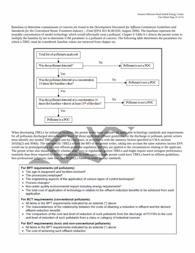
Ameren Missouri-Rush Island Energy Center Fact Sheet Page 21 of 51
Baselines to determine contaminants of concern are found in the Development Document for Effluent Limitations Guidelines and Standards for the Centralized Waste Treatment Industry – Final (EPA 821-R-00-020; August 2000). The baselines represent the treatable concentration of model technology which would effectually treat a pollutant. Chapter 6 Table 6-1 directs the permit writer to multiply the baseline by ten to determine if the parameter is a pollutant of concern. The following table determines the parameters for which a TBEL must be considered; baseline values are retrieved from chapter six.
When developing TBELs for industrial facilities, the permit writer must consider all applicable technology standards and requirements for all pollutants discharged above baseline level. Without applicable effluent guidelines for the discharge or pollutant, permit writers must identify any needed TBELs on a case-by-case basis, in accordance with the statutory factors specified in CWA sections 301(b)(2) and 304(b). The site-specific TBELs reflect the BPJ of the permit writer, taking into account the same statutory factors EPA would use in promulgating a national effluent guideline regulation, but they are applied to the circumstances relating to the applicant. The permit writer also should identify whether state laws or regulations govern TBELs and might require more stringent performance standards than those required by federal regulations. In some cases, a single permit could have TBELs based on effluent guidelines, best professional judgment, state law, and WQBELs based on water quality standards.
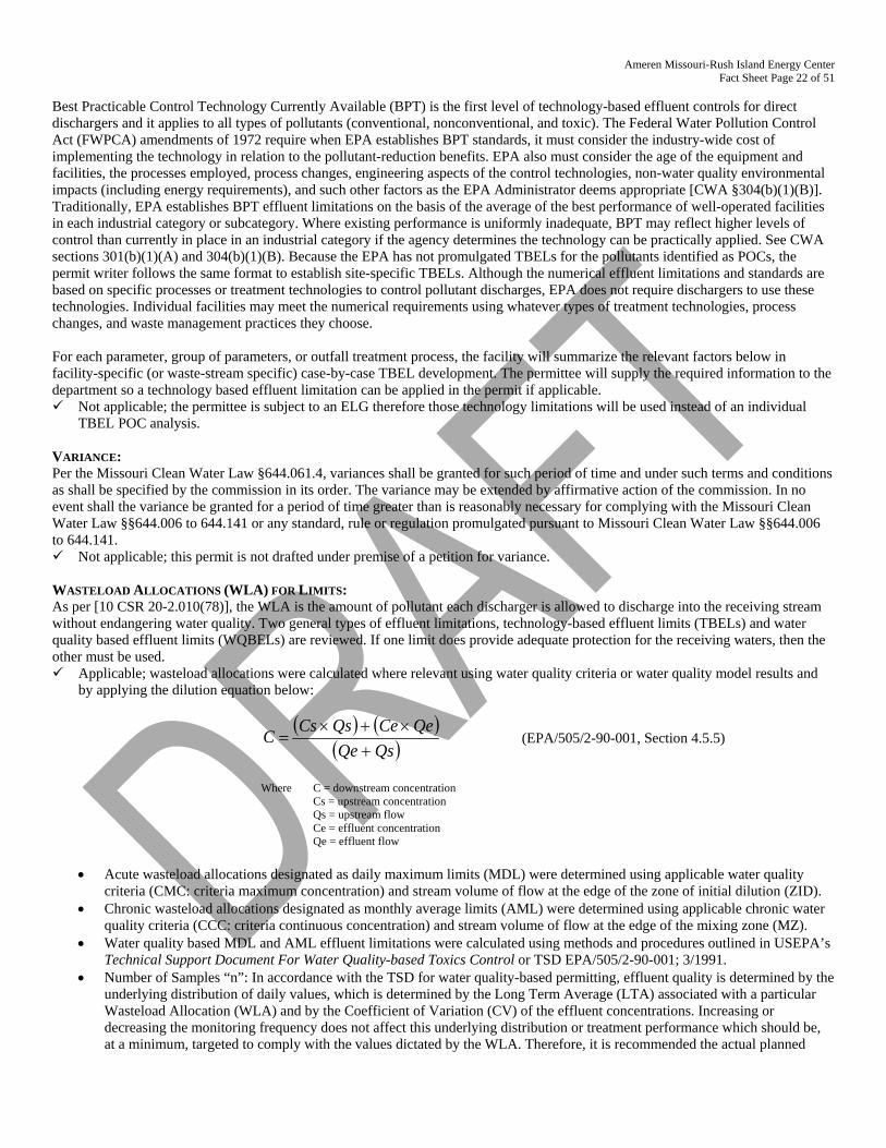
Ameren Missouri-Rush Island Energy Center Fact Sheet Page 22 of 51
Best Practicable Control Technology Currently Available (BPT) is the first level of technology-based effluent controls for direct dischargers and it applies to all types of pollutants (conventional, nonconventional, and toxic). The Federal Water Pollution Control Act (FWPCA) amendments of 1972 require when EPA establishes BPT standards, it must consider the industry-wide cost of implementing the technology in relation to the pollutant-reduction benefits. EPA also must consider the age of the equipment and facilities, the processes employed, process changes, engineering aspects of the control technologies, non-water quality environmental impacts (including energy requirements), and such other factors as the EPA Administrator deems appropriate [CWA §304(b)(1)(B)]. Traditionally, EPA establishes BPT effluent limitations on the basis of the average of the best performance of well-operated facilities in each industrial category or subcategory. Where existing performance is uniformly inadequate, BPT may reflect higher levels of control than currently in place in an industrial category if the agency determines the technology can be practically applied. See CWA sections 301(b)(1)(A) and 304(b)(1)(B). Because the EPA has not promulgated TBELs for the pollutants identified as POCs, the permit writer follows the same format to establish site-specific TBELs. Although the numerical effluent limitations and standards are based on specific processes or treatment technologies to control pollutant discharges, EPA does not require dischargers to use these technologies. Individual facilities may meet the numerical requirements using whatever types of treatment technologies, process changes, and waste management practices they choose. For each parameter, group of parameters, or outfall treatment process, the facility will summarize the relevant factors below in facility-specific (or waste-stream specific) case-by-case TBEL development. The permittee will supply the required information to the department so a technology based effluent limitation can be applied in the permit if applicable. Not applicable; the permittee is subject to an ELG therefore those technology limitations will be used instead of an individual
TBEL POC analysis. VARIANCE: Per the Missouri Clean Water Law §644.061.4, variances shall be granted for such period of time and under such terms and conditions as shall be specified by the commission in its order. The variance may be extended by affirmative action of the commission. In no event shall the variance be granted for a period of time greater than is reasonably necessary for complying with the Missouri Clean Water Law §§644.006 to 644.141 or any standard, rule or regulation promulgated pursuant to Missouri Clean Water Law §§644.006 to 644.141. Not applicable; this permit is not drafted under premise of a petition for variance. WASTELOAD ALLOCATIONS (WLA) FOR LIMITS: As per [10 CSR 20-2.010(78)], the WLA is the amount of pollutant each discharger is allowed to discharge into the receiving stream without endangering water quality. Two general types of effluent limitations, technology-based effluent limits (TBELs) and water quality based effluent limits (WQBELs) are reviewed. If one limit does provide adequate protection for the receiving waters, then the other must be used. Applicable; wasteload allocations were calculated where relevant using water quality criteria or water quality model results and
by applying the dilution equation below:
( ) ( )( )QsQe
QeCeQsCsC+
×+×= (EPA/505/2-90-001, Section 4.5.5)
Where C = downstream concentration
Cs = upstream concentration Qs = upstream flow Ce = effluent concentration Qe = effluent flow
• Acute wasteload allocations designated as daily maximum limits (MDL) were determined using applicable water quality
criteria (CMC: criteria maximum concentration) and stream volume of flow at the edge of the zone of initial dilution (ZID). • Chronic wasteload allocations designated as monthly average limits (AML) were determined using applicable chronic water
quality criteria (CCC: criteria continuous concentration) and stream volume of flow at the edge of the mixing zone (MZ). • Water quality based MDL and AML effluent limitations were calculated using methods and procedures outlined in USEPA’s
Technical Support Document For Water Quality-based Toxics Control or TSD EPA/505/2-90-001; 3/1991. • Number of Samples “n”: In accordance with the TSD for water quality-based permitting, effluent quality is determined by the
underlying distribution of daily values, which is determined by the Long Term Average (LTA) associated with a particular Wasteload Allocation (WLA) and by the Coefficient of Variation (CV) of the effluent concentrations. Increasing or decreasing the monitoring frequency does not affect this underlying distribution or treatment performance which should be, at a minimum, targeted to comply with the values dictated by the WLA. Therefore, it is recommended the actual planned
Ameren Missouri-Rush Island Energy Center Fact Sheet Page 23 of 51
frequency of monitoring normally be used to determine the value of “n” for calculating the AML. However, in situations where monitoring frequency is once per month or less, a higher value for “n” must be assumed for AML derivation purposes. Thus, the statistical procedure being employed using an assumed number of samples is “n = 4” at a minimum. For total ammonia as nitrogen, “n = 30” is used.
WLA MODELING: Permittees may submit site specific studies to better determine the site specific wasteload allocations applied in permits. Not applicable; a WLA study was either not submitted or determined not applicable by department staff. WATER QUALITY STANDARDS: Per 10 CSR 20-7.031(4), general criteria shall be applicable to all waters of the state at all times including mixing zones. Additionally, 40 CFR 122.44(d)(1) directs the department to establish in each NPDES permit to include conditions to achieve water quality established under Section 303 of the Clean Water Act, including state narrative criteria for water quality. WHOLE EFFLUENT TOXICITY (WET) TEST: A WET test is a quantifiable method to determine discharges from the facility cause toxicity to aquatic life by itself, in combination with, or through synergistic responses, when mixed with receiving stream water. Applicable; under the federal Clean Water Act (CWA) §101(a)(3), requiring WET testing is reasonably appropriate for site-
specific Missouri State Operating Permits for discharges to waters of the state issued under the National Pollutant Discharge Elimination System (NPDES). WET testing is also required by 40 CFR 122.44(d)(1). WET testing ensures the provisions in 10 CSR 20-6 and the Water Quality Standards in 10 CSR 20-7 are being met. Under 10 CSR 20-6.010(8)(A)4, the department may require other terms and conditions it deems necessary to assure compliance with the CWA and related regulations of the Missouri Clean Water Commission. The following Missouri Clean Water Laws (MCWL) apply: §644.051.3. requires the department to set permit conditions complying with the MCWL and CWA; §644.051.4 specifically references toxicity as an item we must consider in writing permits (along with water quality-based effluent limits); and §644.051.5. is the basic authority to require testing conditions. WET tests are required by all facilities meeting the following criteria:
Facility is a designated a Major Facility continuously or routinely exceeds its design flow Facility that exceeds its design population equivalent (PE) for BOD5 whether or not its design flow is being exceeded Facility (whether primarily domestic or industrial) that alters its production process throughout the year Facility handles large quantities of toxic substances, or substances that are toxic in large amounts Facility has Water Quality-Based Effluent Limitations for toxic substances (other than NH3) Facility is a municipality with a Design Flow ≥ 22,500 GPD Other – please justify
Part IV. 2013 WATER QUALITY CRITERIA FOR AMMONIA Upcoming changes to the Water Quality Standard for ammonia may require significant upgrades to wastewater treatment facilities. On August 22, 2013, the U.S. Environmental Protection Agency (EPA) finalized new water quality criteria for ammonia, based on toxicity studies of mussels and gill breathing snails. Missouri’s current ammonia criteria are based on toxicity testing of several species, but did not include data from mussels or gill breathing snails. Missouri is home to 69 of North America’s mussel species, which are spread across the state. According to the Missouri Department of Conservation nearly two-thirds of the mussel species in Missouri are considered to be “of conservation concern”. Nine species are listed as federally endangered, with an additional species currently proposed as endangered and another species proposed as threatened. The adult forms of mussels that are seen in rivers, lakes, and streams are sensitive to pollutants because they are sedentary filter feeders. They vacuum up many pollutants with the food they bring in and cannot escape to new habitats, so they can accumulate toxins in their bodies and die. But very young mussels, called glochidia, are exceptionally sensitive to ammonia in water. As a result of a citizen suit, the EPA was compelled to conduct toxicity testing and develop ammonia water quality criteria that would be protective if young mussels may be present in a waterbody. These new criteria will apply to any discharge with ammonia levels that may pose a reasonable potential to violate the standards. Nearly all discharging domestic wastewater treatment facilities (cities, subdivisions, mobile home parks, etc.), as well as certain industrial and stormwater dischargers with ammonia in their effluent, will be affected by this change in the regulations.
Ameren Missouri-Rush Island Energy Center Fact Sheet Page 24 of 51
When new water quality criteria are established by the EPA, states must adopt them into their regulations in order to keep their authorization to issue permits under the National Pollutant Discharge Elimination System (NPDES). States are required to review their water quality standards every three years, and if new criteria have been developed they must be adopted. States may be more protective than the Federal requirements, but not less protective. Missouri does not have the resources to conduct the studies necessary for developing new water quality standards, and therefore our standards mirror those developed by the EPA; however, we will utilize any available flexibility based on actual species of mussels that are native to Missouri and their sensitivity to ammonia. Many treatment facilities in Missouri are currently scheduled to be upgraded to comply with the current water quality standards. But these new ammonia standards may require a different treatment technology than the one being considered by the permittee. It is important that permittees discuss any new and upcoming requirements with their consulting engineers to ensure that their treatment systems are capable of complying with the new requirements. The Department encourages permittees to construct treatment technologies that can attain effluent quality that supports the EPA ammonia criteria. Ammonia toxicity varies by temperature and by pH of the water. Assuming a stable pH value, but taking into account winter and summer temperatures, Missouri includes two seasons of ammonia effluent limitations. Current effluent limitations in this permit are monitoring only for summer and winter. Under the new EPA criteria, where mussels of the family Unionidae are present or expected to be present, the estimated effluent limitations for a facility in a location such as this that discharges to a receiving stream with the mixing consideration listed in Part V of the Fact Sheet will be:
Summer – 37.3 mg/L daily maximum, 14.2 mg/L monthly average. Winter – 142.9 mg/L daily maximum, 54.6 mg/L monthly average.
Actual effluent limits will depend in part on the actual performance of the facility. Operating permits for facilities in Missouri must be written based on current statutes and regulations. Therefore permits will be written with the existing effluent limitations until the new standards are adopted. To aid permittees in decision making, an advisory will be added to permit Fact Sheets notifying permittees of the expected effluent limitations for ammonia. When setting schedules of compliance for ammonia effluent limitations, consideration will be given to facilities that have recently constructed upgraded facilities to meet the current ammonia limitations. For more information on this topic feel free to contact the Missouri Department of Natural Resources, Water Protection Program, Water Pollution Control Branch, Operating Permits Section at (573) 751-1300. Part V. EFFLUENT LIMITS DETERMINATION Effluent limitations derived and established in the below effluent limitations table are based on current operations of the facility. Effluent means both process water and stormwater. Any flow through the outfall is considered a discharge and must be sampled and reported as provided below. Future permit action due to facility modification may contain new operating permit terms and conditions that supersede the terms and conditions, including effluent limitations, of this operating permit. Daily maximums and monthly averages are required under 40 CFR 122.45(d)(1) for continuous discharges not from a POTW. GENERAL CRITERIA CONSIDERATIONS: In accordance with 40 CFR 122.44(d)(1), effluent limitations shall be placed into permits for pollutants which have been determined to cause, have the reasonable potential to cause, or to contribute to an excursion above any State water quality standard, including State narrative criteria for water quality. The rule further states pollutants which have been determined to cause, have the reasonable potential to cause, or contribute to an excursion above a narrative criterion within an applicable State water quality standard, the permit shall contain a numeric effluent limitation to protect that narrative criterion. The previous permit included the narrative criteria as specific prohibitions placed upon the discharge. These prohibitions were included in the permit absent any discussion of the discharge’s reasonable potential to cause or contribute to an excursion of the criterion. In order to comply with this regulation, the permit writer has completed a reasonable potential determination on whether the discharge has reasonable potential to cause, or contribute to an excursion of the general criteria listed in 10 CSR 20-7.031(4). These specific requirements are listed below followed by derivation and discussion (the lettering matches that of the rule itself, under 10 CSR 20-7.031(4)). In instances where reasonable potential exists, the permit includes numeric limitations to address the reasonable potential. In instances where reasonable potential does not exist the permit includes monitoring of the discharges potential to impact the receiving stream’s narrative criteria. Finally, all of the previous permit narrative criteria prohibitions have been removed from the permit given they are addressed by numeric limits where reasonable potential exists. It should also be noted that Section 644.076.1, RSMo as well as Section D – Administrative Requirements of Standard Conditions Part I of this permit state that it shall be unlawful for any person to cause or permit any discharge of water contaminants from any water contaminant or point source located in Missouri that is in violation of sections 644.006 to 644.141 of the Missouri Clean Water Law or any standard, rule, or regulation promulgated by the commission.
Ameren Missouri-Rush Island Energy Center Fact Sheet Page 25 of 51
(A) Waters shall be free from substances in sufficient amounts to cause the formation of putrescent, unsightly or harmful bottom
deposits or prevent full maintenance of beneficial uses. • For all outfalls, there is no RP for putrescent bottom deposits preventing full maintenance of beneficial uses because nothing
disclosed by the permittee at renewal for these outfalls indicates putrescent wastewater would be discharged from the facility. • For all outfalls, there is no RP for unsightly or harmful bottom deposits preventing full maintenance of beneficial uses
because all outfalls have TSS limitations, however, they are all based on technology for the processes involved; values discharged from all outfalls are typically below WQ limitations, therefore no RP.
(B) Waters shall be free from oil, scum and floating debris in sufficient amounts to be unsightly or prevent full maintenance of
beneficial uses. • For all outfalls, there is no RP for oil in sufficient amounts to be unsightly preventing full maintenance of beneficial uses
because nothing disclosed by the permittee at renewal or during prior sampling for DMR requirements for these outfalls indicates oil will be present in sufficient amounts to impair beneficial uses.
• For all outfalls, there is no RP for scum and floating debris in sufficient amounts to be unsightly preventing full maintenance of beneficial uses because nothing disclosed by the permittee at renewal for these outfalls indicates scum and floating debris will be present in sufficient amounts to impair beneficial uses
• The permit contains a special condition addressing fuel spills or fuel releases to the environment. Compliance with the best management practices required within that special condition will prevent fuel from being discharged through the outfall in amounts sufficient enough to create a sheen. Additionally, there are no activities occurring on the site that would result in floating debris in the discharge. The best management practices are sufficient to protect the general water quality standard.
(C) Waters shall be free from substances in sufficient amounts to cause unsightly color or turbidity, offensive odor or prevent full
maintenance of beneficial uses. • For all outfalls, there is no RP for unsightly color or turbidity in sufficient amounts preventing full maintenance of beneficial
uses because nothing disclosed by the permittee at renewal for these outfalls indicates unsightly color or turbidity will be present in sufficient amounts to impair beneficial uses.
• For all outfalls, there is no RP for offensive odor in sufficient amounts preventing full maintenance of beneficial uses because nothing disclosed by the permittee at renewal for these outfalls indicates offensive odor will be present in sufficient amounts to impair beneficial uses.
(D) Waters shall be free from substances or conditions in sufficient amounts to result in toxicity to human, animal or aquatic life.
• This facility has numeric effluent limitations for WET testing; specific toxic pollutants are discussed below in Derivation and Discussion of Limits, and where appropriate, numeric effluent limitations added.
• The permit writer already considered specific toxic pollutants. Numeric effluent limitations are included for those pollutants that could be discharged in toxic amounts. These effluent limitations are protective of human health, animals, and aquatic life.
(E) There shall be no significant human health hazard from incidental contact with the water.
• This facility has numeric effluent limitations for WET testing; specific toxic pollutants are discussed below in Derivation and Discussion of Limits, and where appropriate, numeric effluent limitations added.
• Much like the condition above, the permit writer has already considers specific toxic pollutants, including those pollutants that could cause human health hazards. The discharge is already limited by numeric effluent limitations for those conditions that could result in human health hazards.
• It is the permit writer’s opinion that this criterion is the same as (D). • Much like the condition above, the permit writer has already considers specific toxic pollutants, including those pollutants
that could cause human health hazards. The discharge is already limited by numeric effluent limitations for those conditions that could result in human health hazards.
Ameren Missouri-Rush Island Energy Center Fact Sheet Page 26 of 51
(F) There shall be no acute toxicity to livestock or wildlife watering.
• This facility has numeric effluent limitations for WET testing; specific toxic pollutants are discussed below in Derivation and Discussion of Limits, and where appropriate, numeric effluent limitations added.
• The permit writer already considered specific toxic pollutants. Numeric effluent limitations are included for those pollutants that could be discharged in toxic amounts. These effluent limitations are protective of human health, animals, and aquatic life.
• Much like the condition above, the permit writer has already considers specific toxic pollutants, including those pollutants that could cause human health hazards. The discharge is already limited by numeric effluent limitations for those conditions that could result in human health hazards.
• It is the permit writer’s opinion that this criterion is the same as (D). (G) Waters shall be free from physical, chemical or hydrologic changes that would impair the natural biological community.
• For all outfalls, there is no RP for physical changes that would impair the natural biological community because nothing disclosed by the permittee at renewal for these outfalls indicates physical changes that would impair the natural biological community.
• For outfalls #002-#004, #008 and #009, there is no RP for chemical changes that would impair the natural biological community because nothing disclosed by the permittee at renewal for these outfalls indicates chemical changes that would impair the natural biological community.
• For all outfalls, there is no RP for hydrologic changes that would impair the natural biological community because nothing disclosed by the permittee at renewal for these outfalls indicates physical changes that would impair the natural biological community.
• It has previously been established that any chemical changes are covered by the specific numeric effluent limitations established in the permit. Equalized flow results in lower rates of discharge, thus reducing the scour and erosion potential that could cause these physical changes. The equalized discharge will not have significant impact on the high stream flows. The discharge will not create any changes to hydrologic characteristics that would alter natural stream conditions during precipitation events.
(H) Waters shall be free from used tires, car bodies, appliances, demolition debris, used vehicles or equipment and solid waste as
defined in Missouri's Solid Waste Law, section 260.200, RSMo, except as the use of such materials is specifically permitted pursuant to section 260.200-260.247. • There are no solid waste disposal activities or any operation that has reasonable potential to cause or contribute to the
materials listed above being discharged through any outfall. • Effluent limitations, benchmarks, and permit conditions derived and established in the below effluent limitations tables are
based on current operations of the facility. Future permit action due to facility modification may contain new operating permit terms and conditions that supersede the terms and conditions, including effluent limitations, of this operating permit.
• Daily maximums and monthly averages are required under 40 CFR 122.45(d)(1) for continuous discharges not from a POTW.
• The nearest drinking water intake is located at St. Louis. The Mississippi River has other drinking water intakes south of Rush Island on the Missouri side. Therefore the drinking water (DW) use is in effect and DW limits may apply if they are more stringent and applicable than other uses’ limits.
• Technology based limitations apply to this facility. OUTFALL #001: ONCE-THROUGH COOLING WATER The minimum frequency the department is allowed to apply sampling requirements for a facility is yearly per 40 CFR 122.44(i)(iv)(A)(2). Table A-3 in the permit describes conditional sampling. Each year, even if chlorine or biocides are not used, to comply with yearly reporting, the facility will submit a short report to the St. Louis Regional Office. The facility must collect samples and analyze for free available chlorine, total residual chlorine, upon every occasion (daily, concurrently) of chlorine use. The facility is not required to sample for chlorine if the biocide used is not chlorine based. However, the facility must still collect a sample for WET testing (daily, concurrently) upon biocide/molluskicide use.
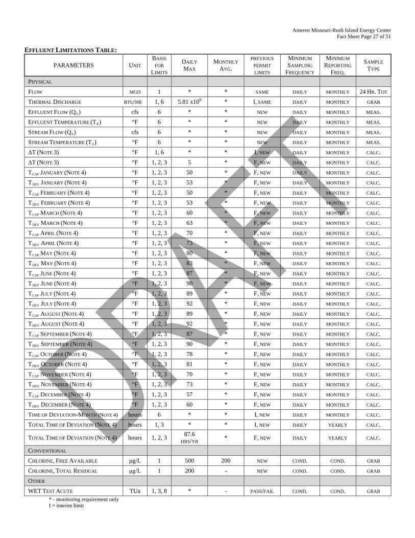
Ameren Missouri-Rush Island Energy Center Fact Sheet Page 27 of 51
EFFLUENT LIMITATIONS TABLE:
PARAMETERS UNIT BASIS
FOR LIMITS
DAILY MAX
MONTHLY AVG.
PREVIOUS PERMIT LIMITS
MINIMUM SAMPLING
FREQUENCY
MINIMUM REPORTING
FREQ.
SAMPLE TYPE
PHYSICAL
FLOW MGD 1 * * SAME DAILY MONTHLY 24 HR. TOT
THERMAL DISCHARGE BTU/HR 1, 6 5.81 x10⁹ * I, SAME DAILY MONTHLY GRAB
EFFLUENT FLOW (QE) cfs 6 * * NEW DAILY MONTHLY MEAS.
EFFLUENT TEMPERATURE (TE) °F 6 * * NEW DAILY MONTHLY MEAS.
STREAM FLOW (QS) cfs 6 * * NEW DAILY MONTHLY MEAS.
STREAM TEMPERATURE (TS) °F 6 * * NEW DAILY MONTHLY MEAS.
ΔT (NOTE 3) °F 1, 6 * * I, NEW DAILY MONTHLY CALC.
ΔT (NOTE 3) °F 1, 2, 3 5 * F, NEW DAILY MONTHLY CALC.
TCAP JANUARY (NOTE 4) °F 1, 2, 3 50 * F, NEW DAILY MONTHLY CALC.
TDEV JANUARY (NOTE 4) °F 1, 2, 3 53 * F, NEW DAILY MONTHLY CALC.
TCAP FEBRUARY (NOTE 4) °F 1, 2, 3 50 * F, NEW DAILY MONTHLY CALC.
TDEV FEBRUARY (NOTE 4) °F 1, 2, 3 53 * F, NEW DAILY MONTHLY CALC.
TCAP MARCH (NOTE 4) °F 1, 2, 3 60 * F, NEW DAILY MONTHLY CALC.
TDEV MARCH (NOTE 4) °F 1, 2, 3 63 * F, NEW DAILY MONTHLY CALC.
TCAP APRIL (NOTE 4) °F 1, 2, 3 70 * F, NEW DAILY MONTHLY CALC.
TDEV APRIL (NOTE 4) °F 1, 2, 3 73 * F, NEW DAILY MONTHLY CALC.
TCAP MAY (NOTE 4) °F 1, 2, 3 80 * F, NEW DAILY MONTHLY CALC.
TDEV MAY (NOTE 4) °F 1, 2, 3 83 * F, NEW DAILY MONTHLY CALC.
TCAP JUNE (NOTE 4) °F 1, 2, 3 87 * F, NEW DAILY MONTHLY CALC.
TDEV JUNE (NOTE 4) °F 1, 2, 3 90 * F, NEW DAILY MONTHLY CALC.
TCAP JULY (NOTE 4) °F 1, 2, 3 89 * F, NEW DAILY MONTHLY CALC.
TDEV JULY (NOTE 4) °F 1, 2, 3 92 * F, NEW DAILY MONTHLY CALC.
TCAP AUGUST (NOTE 4) °F 1, 2, 3 89 * F, NEW DAILY MONTHLY CALC.
TDEV AUGUST (NOTE 4) °F 1, 2, 3 92 * F, NEW DAILY MONTHLY CALC.
TCAP SEPTEMBER (NOTE 4) °F 1, 2, 3 87 * F, NEW DAILY MONTHLY CALC.
TDEV SEPTEMBER (NOTE 4) °F 1, 2, 3 90 * F, NEW DAILY MONTHLY CALC.
TCAP OCTOBER (NOTE 4) °F 1, 2, 3 78 * F, NEW DAILY MONTHLY CALC.
TDEV OCTOBER (NOTE 4) °F 1, 2, 3 81 * F, NEW DAILY MONTHLY CALC.
TCAP NOVEMBER (NOTE 4) °F 1, 2, 3 70 * F, NEW DAILY MONTHLY CALC.
TDEV NOVEMBER (NOTE 4) °F 1, 2, 3 73 * F, NEW DAILY MONTHLY CALC.
TCAP DECEMBER (NOTE 4) °F 1, 2, 3 57 * F, NEW DAILY MONTHLY CALC.
TDEV DECEMBER (NOTE 4) °F 1, 2, 3 60 * F, NEW DAILY MONTHLY CALC.
TIME OF DEVIATION-MONTH (NOTE 4) hours 6 * * I, NEW DAILY MONTHLY CALC.
TOTAL TIME OF DEVIATION (NOTE 4) hours 1, 3 * * I, NEW DAILY YEARLY CALC.
TOTAL TIME OF DEVIATION (NOTE 4) hours 1, 2, 3 87.6 HRS/YR * F, NEW DAILY YEARLY CALC.
CONVENTIONAL
CHLORINE, FREE AVAILABLE µg/L 1 500 200 NEW COND. COND. GRAB
CHLORINE, TOTAL RESIDUAL μg/L 1 200 - NEW COND. COND. GRAB
OTHER
WET TEST ACUTE TUa 1, 3, 8 * - PASS/FAIL COND. COND. GRAB * - monitoring requirement only I = interim limit
Ameren Missouri-Rush Island Energy Center Fact Sheet Page 28 of 51
F = final limit new - parameter not in previous permit calc. – calculation meas. – measured cond. – conditional
Basis for Limitations Codes: 1. State or Federal Regulation/Law 5. Water Quality Model 2. Water Quality Standard (includes RPA) 6. Best Professional Judgment 3. Water Quality Based Effluent Limits 7. TMDL or Permit in lieu of TMDL 4. Antidegradation Review/Policy 8. WET Test Policy
Note 3: ΔT = [((Qs/4)Ts + QeTe) / ((Qs/4) + Qe)] - Ts
Where: ΔT the change in temperature in °F at the edge of the thermal mixing zone Qs/4 the receiving stream flow in cfs divided by 4 Qe effluent flow in cfs Ts measured stream temperature Te measured temperature of effluent
Note 4: To calculate the temperature of the stream at the edge of the mixing zone, the facility will use the following equation:
Designated as Temz in the equation below, the facility can determine compliance with Tdev, Tcap, and percent time deviation allowance.
Temz = [((Qs/4)Ts + QeTe) / ((Qs/4) + Qe))]
Where: Temz the temperature of the receiving stream at the edge of the thermal mixing zone Qs/4 the receiving stream flow in cfs divided by 4 Qe effluent flow in cfs Ts measured stream temperature Te measured temperature of effluent
Temperature cap (designated as Tcap in Table A-2 of the permit and the Effluent Limitations Table of the fact sheet) is the effluent temperature in the receiving stream at the edge of the thermal mixing zone. It may be exceeded for no more than 1% of the year (87.6 hours).
Temperature deviation (designated as Tdev in Table A-2 of the permit and the Effluent Limitations Table of the fact sheet) is the maximum effluent temperature limit applicable in the receiving stream at the edge of the thermal mixing zone which may not be exceeded. MoCWIS is set up to receive one value for the thermal limitations for each month. The facility will violate the thermal limit if the value entered in MoCWIS is above the Tdev value for the month.
Percent Time Deviation Allowance: Missouri’s Water Quality Standards allows permittees to exceed their applicable Tcap criteria (but not the Tdev criteria) for 1% of the year in Zone C along the Mississippi River. The time of deviation allowance shall be tracked in hours per year any time their calculated temperature values exceed a specific month’s daily maximum Tcap effluent limit. The permittee is required to monitor and report the total monthly exceedance time. a) If Temz is less than Tcap then the permittee records “0” hours deviation. b) Any time Temz is above Tcap then the facility reports the number of hours of deviation. c) The permittee shall report on January 28th of each year the total number of hours the facility exceeded their temperature
cap effluent limits for the entire year.
A violation occurs if: a. The percent time deviation allowance is above 1% (87.6 hours) for the calendar year; and/or b. The Temz value reported is above the Tdev limitation.
Ameren Missouri-Rush Island Energy Center Fact Sheet Page 29 of 51
DERIVATION AND DISCUSSION OF LIMITS:
PHYSICAL: The facility reported color was believed absent. No additional sampling will be required at this time.
Flow In accordance with [40 CFR Part 122.44(i)(1)(ii)] the volume of effluent discharged from each outfall is needed to assure compliance with permitted effluent limitations. If the permittee is unable to obtain effluent flow, then it is the responsibility of the permittee to inform the department, which may require the submittal of an operating permit modification. The facility will report the total flow in millions of gallons per day (MGD).
Temperature The department considered thermal discharge a pollutant of concern for this facility as is required by the CWA. While water quality standards exist, the department must also formulate a review of the technology, limitations associated with that technology, the age of the equipment, and the processes involved at the facility. Please see both sections below; Water Quality Limitations and Technology Based Effluent Limitations.
WATER QUALITY LIMITATIONS:
In accordance with 10 CSR 20-7.031(5)(D)5. water contaminant sources shall not cause or contribute to Mississippi River temperature in excess of the temperatures listed in the effluent limitations table. The facility is located between Lock and Dam No. 26 and the Missouri-Arkansas state line, therefore the facility is in Zone 2C. Missouri’s WQS temperature criteria [10 CSR 20-7.031(5)(D)1. through (5)(D)6.] establish two main areas of compliance for all habitats. The first compliance requirement deals with the change of temperature in degrees Fahrenheit stated as delta temperature (or ΔT). The second compliance requirement deals with the result of a calculation of the receiving stream’s temperature not to exceed (Tdev) at the edge of the thermal mixing zone. Missouri’s WQS temperature criteria for warm water habitats (WWH) [10 CSR 20-7.031(5)(D)1.] establishes thermal discharges cannot cause a change in the receiving stream’s temperature (ΔT) of more than five (5) degrees and a Tcap of 90°F. Missouri’s WQS establishes specific Tcap values for discharges to the Mississippi River in [10 CSR 20-7.031(5)(D)5.] to which this facility applies. The regulation also establishes a percent, in time, deviation allowance from the established Tcap for the Mississippi River as well as a maximum temperature not to exceed (Tdev) of Tcap +3°F. Both compliance requirements (ΔT and Tcap/dev) are to be established at the edge of the thermal mixing zone (designated as Temz). Thermal mixing zones are established on permanent (P) streams or other streams where available. Mixing zone regulations are contained in [10 CSR 20-7.031(5)(D)6.]. Streams with no mixing considerations must meet ΔT and Tcap at the end of the pipe. Similar to Missouri’s WQS’s toxic mixing considerations which use low-flow considerations (i.e. 7Q10), the temperature regulations require the department establish a thermal mixing zone limited to either 25% of the cross-sectional area or 25% volume of a river. This approach assumes the receiving water is able to consume 100% of the heat energy being discharged. Volume of discharge (for the river and the facility) is measured in cubic feet per second (ft3/sec, or cfs). Typically discharge is obtained from a nearby upstream United States Geological Survey (USGS) or United States Army Corps of Engineers (USACE) gauging station. If there is a significant distance from the facility to the nearest upstream gauging station, it may be in the best interest of the permittee to fund a new gauging station. Additionally, the department will only use gauging station data as a viable source of receiving stream flow. Meaning effluent flows from other point sources may not be considered (i.e. added) to the flow determination. If there is a near-by gauging station downstream of the facility, then the permittee can use this data but must subtract their daily effluent discharge from the receiving stream flow. The department may also have the permittee subtract other inputs as necessary. There are no regulatory requirements to determine a monthly average value for temperature as the regulations are written as short-term maximums. However, the department has determined reporting monthly average for Tcap (Tdev if applicable) and ΔT to be an important measure of trends. Meanings of Equations and Variables: Variables and calculations which may be included in this permit are described as follows. Not all variables will be used in all calculations. • Qe is effluent flow and reported in cubic feet per second (“ft3/sec” or cfs). • Qs is the ambient up-stream stream flow in cfs. It is the department’s expectation the permittee will obtain the Qs data from
an appropriate and nearest upstream United States Geological Survey (USGS) or United States Army Corps of Engineers (USACE) gauging stations.
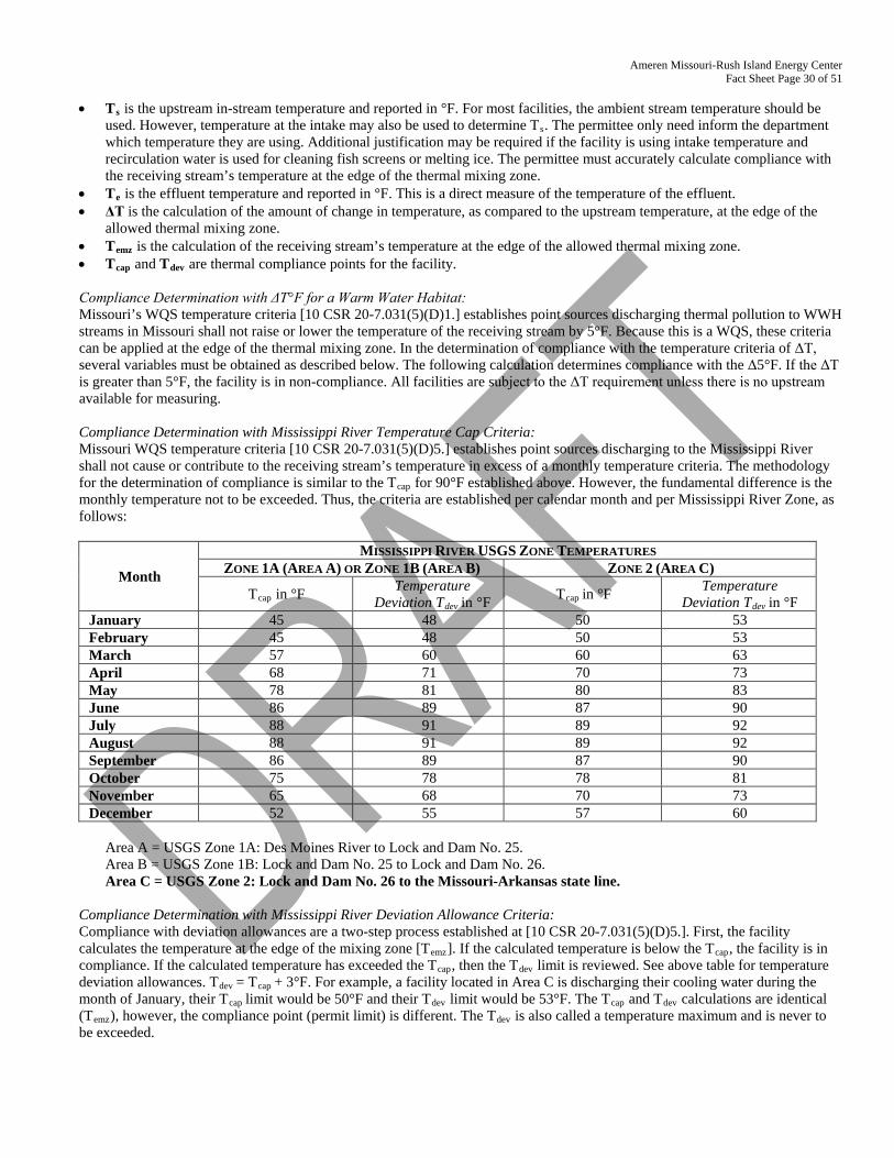
Ameren Missouri-Rush Island Energy Center Fact Sheet Page 30 of 51
• Ts is the upstream in-stream temperature and reported in °F. For most facilities, the ambient stream temperature should be
used. However, temperature at the intake may also be used to determine Ts. The permittee only need inform the department which temperature they are using. Additional justification may be required if the facility is using intake temperature and recirculation water is used for cleaning fish screens or melting ice. The permittee must accurately calculate compliance with the receiving stream’s temperature at the edge of the thermal mixing zone.
• Te is the effluent temperature and reported in °F. This is a direct measure of the temperature of the effluent. • ΔT is the calculation of the amount of change in temperature, as compared to the upstream temperature, at the edge of the
allowed thermal mixing zone. • Temz is the calculation of the receiving stream’s temperature at the edge of the allowed thermal mixing zone. • Tcap and Tdev are thermal compliance points for the facility.
Compliance Determination with ΔT°F for a Warm Water Habitat: Missouri’s WQS temperature criteria [10 CSR 20-7.031(5)(D)1.] establishes point sources discharging thermal pollution to WWH streams in Missouri shall not raise or lower the temperature of the receiving stream by 5°F. Because this is a WQS, these criteria can be applied at the edge of the thermal mixing zone. In the determination of compliance with the temperature criteria of ΔT, several variables must be obtained as described below. The following calculation determines compliance with the Δ5°F. If the ΔT is greater than 5°F, the facility is in non-compliance. All facilities are subject to the ΔT requirement unless there is no upstream available for measuring. Compliance Determination with Mississippi River Temperature Cap Criteria: Missouri WQS temperature criteria [10 CSR 20-7.031(5)(D)5.] establishes point sources discharging to the Mississippi River shall not cause or contribute to the receiving stream’s temperature in excess of a monthly temperature criteria. The methodology for the determination of compliance is similar to the Tcap for 90°F established above. However, the fundamental difference is the monthly temperature not to be exceeded. Thus, the criteria are established per calendar month and per Mississippi River Zone, as follows:
Month
MISSISSIPPI RIVER USGS ZONE TEMPERATURES ZONE 1A (AREA A) OR ZONE 1B (AREA B) ZONE 2 (AREA C)
Tcap in °F Temperature Deviation Tdev in °F Tcap in °F Temperature
Deviation Tdev in °F January 45 48 50 53 February 45 48 50 53 March 57 60 60 63 April 68 71 70 73 May 78 81 80 83 June 86 89 87 90 July 88 91 89 92 August 88 91 89 92 September 86 89 87 90 October 75 78 78 81 November 65 68 70 73 December 52 55 57 60
Area A = USGS Zone 1A: Des Moines River to Lock and Dam No. 25. Area B = USGS Zone 1B: Lock and Dam No. 25 to Lock and Dam No. 26. Area C = USGS Zone 2: Lock and Dam No. 26 to the Missouri-Arkansas state line.
Compliance Determination with Mississippi River Deviation Allowance Criteria: Compliance with deviation allowances are a two-step process established at [10 CSR 20-7.031(5)(D)5.]. First, the facility calculates the temperature at the edge of the mixing zone [Temz]. If the calculated temperature is below the Tcap, the facility is in compliance. If the calculated temperature has exceeded the Tcap, then the Tdev limit is reviewed. See above table for temperature deviation allowances. Tdev = Tcap + 3°F. For example, a facility located in Area C is discharging their cooling water during the month of January, their Tcap limit would be 50°F and their Tdev limit would be 53°F. The Tcap and Tdev calculations are identical (Temz), however, the compliance point (permit limit) is different. The Tdev is also called a temperature maximum and is never to be exceeded.
Ameren Missouri-Rush Island Energy Center Fact Sheet Page 31 of 51
Secondly, if the Tcap has been exceeded, the facility must then determine the amount of time the Tcap was exceeded. Regardless if the Tdev is being exceeded or not, the time (in hours) of Tcap exceedance is still reported. The time deviation allowance, based on the USGS Zone, provides a specific aggregate of hours per year a facility can exceed their monthly Tcap limit. The site-specific criteria for the Mississippi River allows the permittee to exceed their applicable criteria either 1% of the year for Zone 1A and 2C; and 5% of the year for Zone 1B. It has been determined this percent exceedances allowance should be tracked in hours for a calendar year. Zone 1A (Area A) and Zone 2 (Area C) is 1% = [(365)(24)(0.01)] = 87.6 hours (87 hours and 36 minutes) allowed per year. Zone 1B (Area B) is 5% = [(365)(24)(0.05)] = 438 hours allowed per year. The facility is within C. Tracking of time used for percent time deviation allowance, can be captured and tracked via an effluent limit in MoCWIS. Any time a facility exceeds Tcap the time deviation allowance “clock” is running. For every episode the permittee uses their available time, the operating permit shall require the permittee submit the time with their monthly discharge monitoring report (DMR) to state they exceeded their Tcap.
Permit Record of Thermal Limitations: The original NPDES issued for Rush Island Energy Center (then called Rush Island Power Plant) was issued on October 3, 1975. An application package to establish an alternative effluent limitation for the thermal discharge was submitted to the MDNR during August 1979. This submittal consisted of a biological demonstration and assessment for compliance with applicable Missouri Water Quality Standards to support the alternative limitation. On January 14, 1980 the MDNR formally approved the 316(a) demonstration. The subsequent permit was issued on February 18, 1983 established the alternate effluent limitations of 5.43 x10⁹ btu/hr. The permit was renewed in 1989. With the February 4, 1994 permit renewal, MDNR established a revised heat rejection limit of 5.70 x 10⁹ btu/hr as the effluent limit, based on a revised means of calculating heat rejection from the plant electrical load. The permit was subsequently reissued on August 27, 1999 to establish a revised heat rejection limit of 5.81 x 10⁹ btu/hr as the effluent limit. The 5.81 x 10⁹ btu/hr was retained in the October 1, 2004 renewal. In this renewal, 5.81 x 10⁹ btu/hr is an interim limitation before the final effluent limitation based on water quality standards are established.
Prior to this permit, and in the interim, the facility is maintaining WQS for ΔT by using the following calculation: H = Cp * ρ * Q * ∆T
Where: H = BTU/hr Cp = specific heat = 1 BTU/lboF {water} ρ = density = 8.345 lb/gal = 62.429 lb/ft3{water} Q = flow rate gal/hr or gal/min * 60 min/hr ∆T = change or difference in temperature
Re-arranging to calculate ∆T from BTU and flow: ∆T = H / [Cp * ρ * Q] and revising the units {and restating density in lbs/cu ft, with 1 cu ft = 7.481 gal} is:
∆T (oF) = [H (BBTU/hr) * 1,000,000,000 BTU/BBTU] ÷ 62.429 (lb/cu ft) * Q (cu ft/sec) * 3600 (sec/hr)* 1 (BTU/ lb oF) Thus an edge of mixing zone temperature increase can be calculated from: Q/4 or Q*0.25 {allowing for a mixing zone containing 25% of the stream flow} (in cfs or cu ft/sec) HR {as reported in the DMR} (in BBTU/hr or BTU * 109) (HR = heat rejection) An edge of mixing zone river temperature can then be calculated: Temz = ∆T + ambient river T {or intake T to use DMR data} Example: 7Q10 = 56,149 CFS = /4 = Mixing = 14,037.25 CFS HR = 5.81 x 10⁹ BTU/hr = 5,810,000,000 BTU/hr ΔT °F = 5,810,000,000 BTU ÷ [(62.429 lb/ft3) * (14,037.25 ft3/sec {river discharge}) * (3600 sec/hr) * (1BTU/lb °F)] = 5,810,000,000 BTU ÷ 315,4793,328.9 = 1.84164 = ΔT = ~1.8 °F at the edge of the mixing zone. The example shows the ΔT of the facility at low flow conditions. When the facility is reporting the maximum heat rejection, the facility changes the temperature of the discharge by about 1.8 °F. Unfortunately, the above equation does not ensure compliance with Temz.
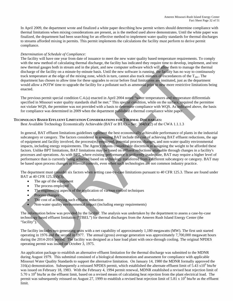
Ameren Missouri-Rush Island Energy Center Fact Sheet Page 32 of 51
In April 2009, the department wrote and finalized a white paper describing how permit writers should determine compliance with thermal limitations when mixing considerations are present, as is the method used above demonstrates. Until the white paper was finalized, the department had been searching for an effective method to implement water quality standards for thermal discharges to streams afforded mixing in permits. This permit implements the calculations the facility must perform to derive permit compliance. Determination of Schedule of Compliance: The facility will have one year from date of issuance to meet the new water quality based temperature requirements. To comply with the new method of calculating thermal discharge, the facility has indicated they require time to develop, implement, and test new thermal gauges both in stream and in the plant, and new computer software which will allow them to manage the thermal discharge of the facility on a minute-by-minute basis. Until the new software is running, the facility has no way to continuously track temperature at the edge of the mixing zone, which in turn, cannot also track minutes of exceedances of the Tdev. The department has chosen to allow time for these upgrades to occur before final limitations are instituted, just as the department would allow a POTW time to upgrade the facility for a pollutant such as ammonia prior to new more restrictive limitations being enacted. The previous permit special condition C.4.(a) enacted in April 2004 noted “water temperatures and temperature differentials specified in Missouri water quality standards shall be met.” This special condition, while on the surface, required the permittee not violate WQS, the permittee was not provided with a basis to determine compliance with WQS. As indicated above, the basis for compliance was determined in 2009 when the department published a thermal compliance white paper.
TECHNOLOGY BASED EFFLUENT LIMITATION CONSIDERATIONS FOR THERMAL DISCHARGES: Best Available Technology Economically Achievable (BAT or BTA) -- Sec. 304(b)(2) of the CWA 1.1.1.3 In general, BAT effluent limitations guidelines represent the best economically achievable performance of plants in the industrial subcategory or category. The factors considered in assessing BAT include the cost of achieving BAT effluent reductions, the age of equipment and facility involved, the process(es) employed, potential process changes, and non-water quality environmental impacts, including energy requirements. The Agency retains considerable discretion in assigning the weight to be afforded these factors. Unlike BPT limitations, BAT limitations may be based on effluent reductions attainable through changes in a facility's processes and operations. As with BPT, where existing performance is uniformly inadequate, BAT may require a higher level of performance than is currently being achieved based on technology transferred from a different subcategory or category. BAT may be based upon process changes or internal controls, even when such technologies are not common industry practice. The department must consider six factors when setting case-by-case limitations pursuant to 40 CFR 125.3. These are found under BAT at 40 CFR 125.3(d)(3).
• The age of the equipment • The process employed • The engineering aspects of the application of various control techniques • Process changes • The cost of achieving such effluent reduction • Non-water quality environmental impact (including energy requirements)
The information below was provided by the facility. The analysis was undertaken by the department to assess a case-by-case technology based effluent limitation (“TBEL”) for thermal discharges from the Ameren Rush Island Energy Center (the “facility”). The facility includes two generating units with a net capability of approximately 1,180 megawatts (MW). The first unit started operating in 1976 and the second in 1977. The annual (gross) average generation was approximately 7,700,000 megawatt hours during the 2014-2016 period. The facility was designed as a base load plant with once-through cooling. The original NPDES operating permit was issued on October 3, 1975. An application package to establish an alternative effluent limitation for the thermal discharge was submitted to the MDNR during August 1979. This submittal consisted of a biological demonstration and assessment for compliance with applicable Missouri Water Quality Standards to support the alternative limitation. On January 14, 1980 the MDNR formally approved the 316(a) demonstration. Subsequently a reissued NPDES permit, which established the alternate effluent limit of 5.43 x10⁹ btu/hr was issued on February 18, 1983. With the February 4, 1994 permit renewal, MDNR established a revised heat rejection limit of 5.70 x 10⁹ btu/hr as the effluent limit, based on a revised means of calculating heat rejection from the plant electrical load. The permit was subsequently reissued on August 27, 1999 to establish a revised heat rejection limit of 5.81 x 10⁹ btu/hr as the effluent limit.
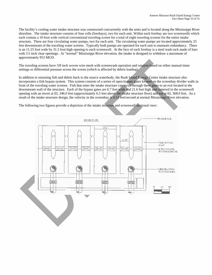
Ameren Missouri-Rush Island Energy Center Fact Sheet Page 33 of 51
The facility’s cooling water intake structure was constructed concurrently with the units and is located along the Mississippi River shoreline. The intake structure consists of four cells (forebays), two for each unit. Within each forebay are two screenwells which each contain a 10-foot wide vertical conventional traveling screen for a total of eight traveling screens for the entire intake structure. There are four circulating water pumps, two for each unit. The circulating water pumps are located approximately 25 feet downstream of the traveling water screens. Typically both pumps are operated for each unit to maintain redundancy. There is an 11.25 foot wide by 31.5 foot high opening to each screenwell. At the face of each forebay is a steel trash rack made of bars with 3.5 inch clear openings. At “normal” Mississippi River elevation, the intake is designed to withdraw a maximum of approximately 953 MGD. The traveling screens have 3/8 inch woven wire mesh with screenwash operation and rotation based on either manual timer settings or differential pressure across the screen (which is affected by debris loading). In addition to returning fish and debris back to the source waterbody, the Rush Island Energy Center intake structure also incorporates a fish bypass system. This system consists of a series of open bypass gates located on the screenbay divider walls in front of the traveling water screens. Fish that enter the intake structure can swim through these gates to an exit located in the downstream wall of the structure. Each of the bypass gates are 6.7 feet wide and 21.6 feet high and centered in the screenwell opening with an invert at EL 346.0 feet (approximately 6.5 feet above the intake structure floor) and top at EL 368.0 feet. As a result of the intake structure design, the velocity in the screenbay is 0.52 feet/second at normal Mississippi River elevation. The following two figures provide a depiction of the intake structure and screenwell sectional view:
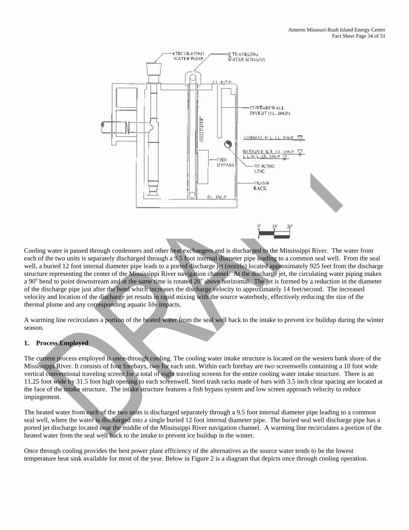
Ameren Missouri-Rush Island Energy Center Fact Sheet Page 34 of 51
Cooling water is passed through condensers and other heat exchangers and is discharged to the Mississippi River. The water from each of the two units is separately discharged through a 9.5 foot internal diameter pipe leading to a common seal well. From the seal well, a buried 12 foot internal diameter pipe leads to a ported discharge jet (nozzle) located approximately 925 feet from the discharge structure representing the center of the Mississippi River navigation channel. At the discharge jet, the circulating water piping makes a 90o bend to point downstream and at the same time is rotated 20o above horizontal. The jet is formed by a reduction in the diameter of the discharge pipe just after the bend which increases the discharge velocity to approximately 14 feet/second. The increased velocity and location of the discharge jet results in rapid mixing with the source waterbody, effectively reducing the size of the thermal plume and any corresponding aquatic life impacts. A warming line recirculates a portion of the heated water from the seal well back to the intake to prevent ice buildup during the winter season. 1. Process Employed The current process employed is once-through cooling. The cooling water intake structure is located on the western bank shore of the Mississippi River. It consists of four forebays, two for each unit. Within each forebay are two screenwells containing a 10 foot wide vertical conventional traveling screen for a total of eight traveling screens for the entire cooling water intake structure. There is an 11.25 foot wide by 31.5 foot high opening to each screenwell. Steel trash racks made of bars with 3.5 inch clear spacing are located at the face of the intake structure. The intake structure features a fish bypass system and low screen approach velocity to reduce impingement. The heated water from each of the two units is discharged separately through a 9.5 foot internal diameter pipe leading to a common seal well, where the water is discharged into a single buried 12 foot internal diameter pipe. The buried seal well discharge pipe has a ported jet discharge located near the middle of the Mississippi River navigation channel. A warming line recirculates a portion of the heated water from the seal well back to the intake to prevent ice buildup in the winter. Once through cooling provides the best power plant efficiency of the alternatives as the source water tends to be the lowest temperature heat sink available for most of the year. Below in Figure 2 is a diagram that depicts once through cooling operation.
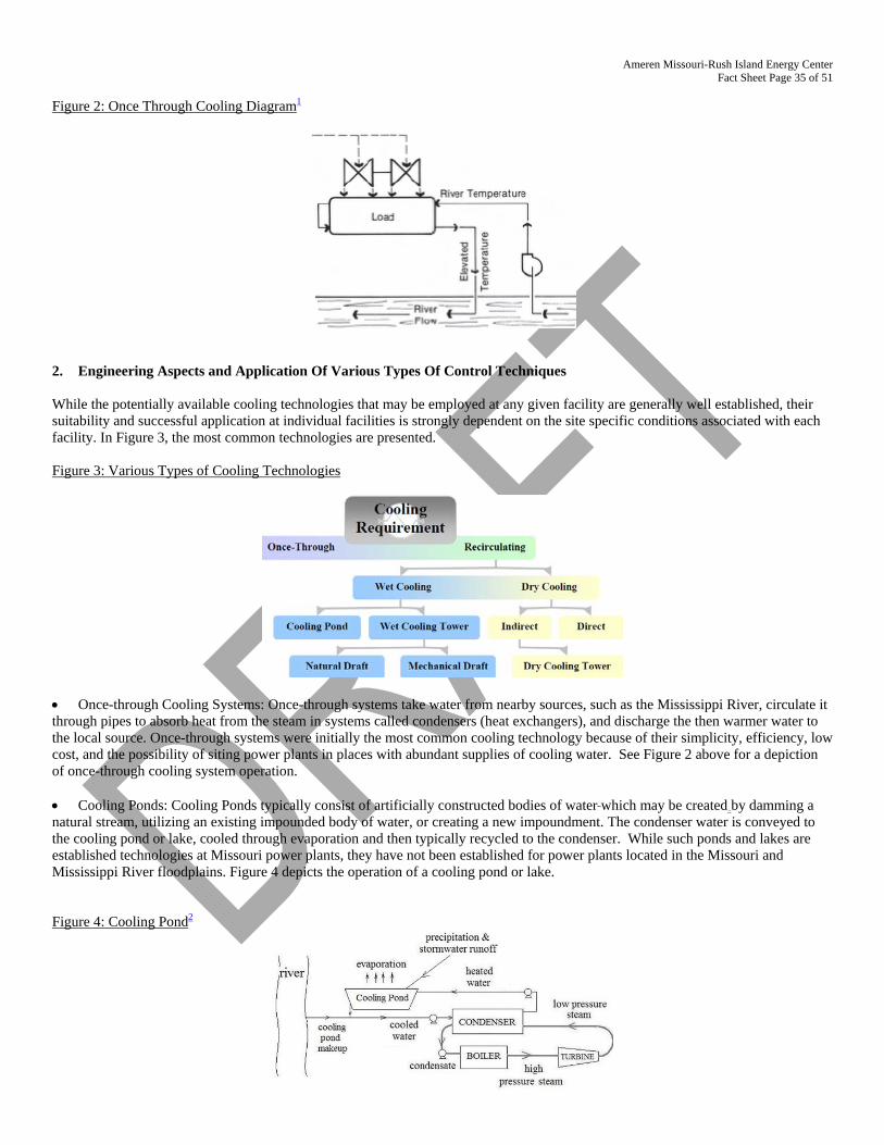
Ameren Missouri-Rush Island Energy Center Fact Sheet Page 35 of 51
Figure 2: Once Through Cooling Diagram1
2. Engineering Aspects and Application Of Various Types Of Control Techniques While the potentially available cooling technologies that may be employed at any given facility are generally well established, their suitability and successful application at individual facilities is strongly dependent on the site specific conditions associated with each facility. In Figure 3, the most common technologies are presented. Figure 3: Various Types of Cooling Technologies
• Once-through Cooling Systems: Once-through systems take water from nearby sources, such as the Mississippi River, circulate it through pipes to absorb heat from the steam in systems called condensers (heat exchangers), and discharge the then warmer water to the local source. Once-through systems were initially the most common cooling technology because of their simplicity, efficiency, low cost, and the possibility of siting power plants in places with abundant supplies of cooling water. See Figure 2 above for a depiction of once-through cooling system operation. • Cooling Ponds: Cooling Ponds typically consist of artificially constructed bodies of water which may be created by damming a natural stream, utilizing an existing impounded body of water, or creating a new impoundment. The condenser water is conveyed to the cooling pond or lake, cooled through evaporation and then typically recycled to the condenser. While such ponds and lakes are established technologies at Missouri power plants, they have not been established for power plants located in the Missouri and Mississippi River floodplains. Figure 4 depicts the operation of a cooling pond or lake. Figure 4: Cooling Pond2
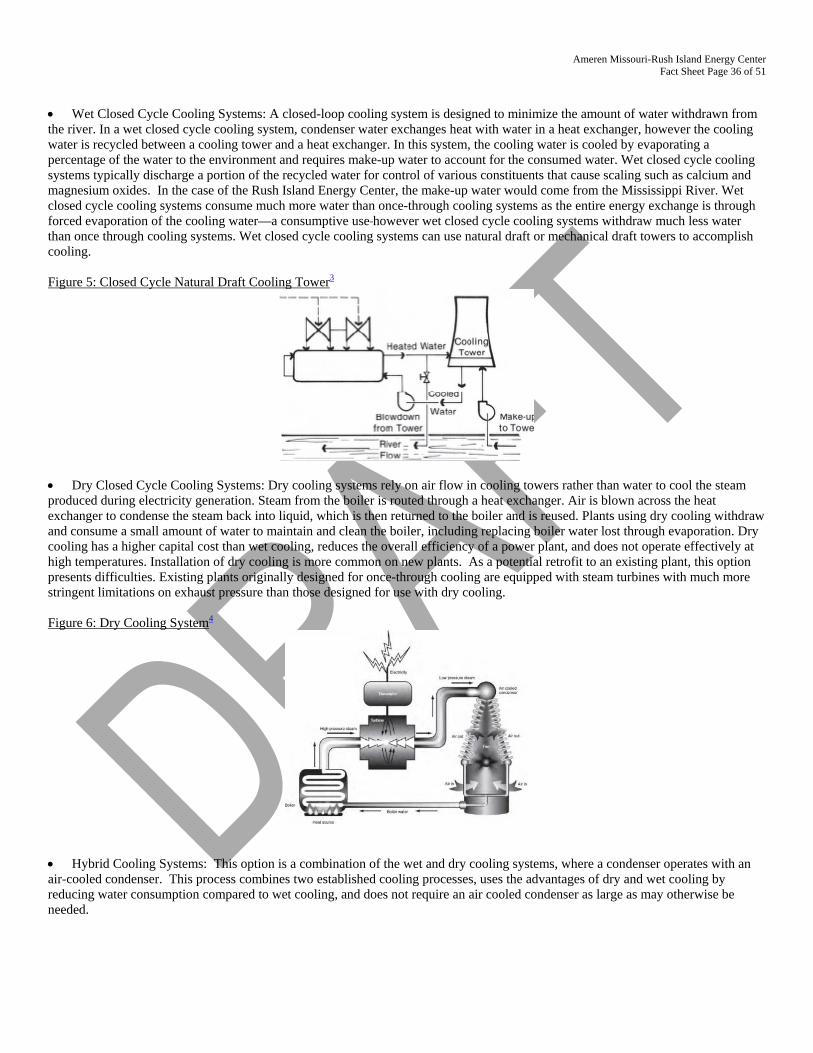
Ameren Missouri-Rush Island Energy Center Fact Sheet Page 36 of 51
• Wet Closed Cycle Cooling Systems: A closed-loop cooling system is designed to minimize the amount of water withdrawn from the river. In a wet closed cycle cooling system, condenser water exchanges heat with water in a heat exchanger, however the cooling water is recycled between a cooling tower and a heat exchanger. In this system, the cooling water is cooled by evaporating a percentage of the water to the environment and requires make-up water to account for the consumed water. Wet closed cycle cooling systems typically discharge a portion of the recycled water for control of various constituents that cause scaling such as calcium and magnesium oxides. In the case of the Rush Island Energy Center, the make-up water would come from the Mississippi River. Wet closed cycle cooling systems consume much more water than once-through cooling systems as the entire energy exchange is through forced evaporation of the cooling water—a consumptive use however wet closed cycle cooling systems withdraw much less water than once through cooling systems. Wet closed cycle cooling systems can use natural draft or mechanical draft towers to accomplish cooling. Figure 5: Closed Cycle Natural Draft Cooling Tower3
• Dry Closed Cycle Cooling Systems: Dry cooling systems rely on air flow in cooling towers rather than water to cool the steam produced during electricity generation. Steam from the boiler is routed through a heat exchanger. Air is blown across the heat exchanger to condense the steam back into liquid, which is then returned to the boiler and is reused. Plants using dry cooling withdraw and consume a small amount of water to maintain and clean the boiler, including replacing boiler water lost through evaporation. Dry cooling has a higher capital cost than wet cooling, reduces the overall efficiency of a power plant, and does not operate effectively at high temperatures. Installation of dry cooling is more common on new plants. As a potential retrofit to an existing plant, this option presents difficulties. Existing plants originally designed for once-through cooling are equipped with steam turbines with much more stringent limitations on exhaust pressure than those designed for use with dry cooling. Figure 6: Dry Cooling System4
• Hybrid Cooling Systems: This option is a combination of the wet and dry cooling systems, where a condenser operates with an air-cooled condenser. This process combines two established cooling processes, uses the advantages of dry and wet cooling by reducing water consumption compared to wet cooling, and does not require an air cooled condenser as large as may otherwise be needed.
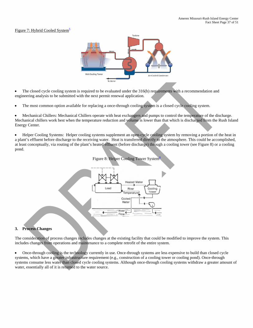
Ameren Missouri-Rush Island Energy Center Fact Sheet Page 37 of 51
Figure 7: Hybrid Cooled System5
• The closed cycle cooling system is required to be evaluated under the 316(b) requirements with a recommendation and engineering analysis to be submitted with the next permit renewal application. • The most common option available for replacing a once-through cooling system is a closed cycle cooling system. • Mechanical Chillers: Mechanical Chillers operate with heat exchangers and pumps to control the temperature of the discharge. Mechanical chillers work best when the temperature reduction and volume is lower than that which is discharged from the Rush Island Energy Center. • Helper Cooling Systems: Helper cooling systems supplement an open-cycle cooling system by removing a portion of the heat in a plant’s effluent before discharge to the receiving water. Heat is transferred directly to the atmosphere. This could be accomplished, at least conceptually, via routing of the plant’s heated effluent (before discharge) through a cooling tower (see Figure 8) or a cooling pond.
Figure 8: Helper Cooling Tower System6
3. Process Changes The consideration of process changes includes changes at the existing facility that could be modified to improve the system. This includes changes from operations and maintenance to a complete retrofit of the entire system. • Once-through cooling is the technology currently in use. Once-through systems are less expensive to build than closed cycle systems, which have a greater infrastructure requirement (e.g., construction of a cooling tower or cooling pond). Once-through systems consume less water than closed cycle cooling systems. Although once-through cooling systems withdraw a greater amount of water, essentially all of it is returned to the water source.
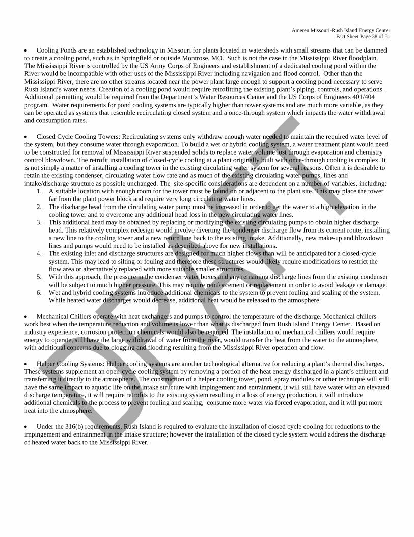
Ameren Missouri-Rush Island Energy Center Fact Sheet Page 38 of 51
• Cooling Ponds are an established technology in Missouri for plants located in watersheds with small streams that can be dammed to create a cooling pond, such as in Springfield or outside Montrose, MO. Such is not the case in the Mississippi River floodplain. The Mississippi River is controlled by the US Army Corps of Engineers and establishment of a dedicated cooling pond within the River would be incompatible with other uses of the Mississippi River including navigation and flood control. Other than the Mississippi River, there are no other streams located near the power plant large enough to support a cooling pond necessary to serve Rush Island’s water needs. Creation of a cooling pond would require retrofitting the existing plant’s piping, controls, and operations. Additional permitting would be required from the Department’s Water Resources Center and the US Corps of Engineers 401/404 program. Water requirements for pond cooling systems are typically higher than tower systems and are much more variable, as they can be operated as systems that resemble recirculating closed system and a once-through system which impacts the water withdrawal and consumption rates. • Closed Cycle Cooling Towers: Recirculating systems only withdraw enough water needed to maintain the required water level of the system, but they consume water through evaporation. To build a wet or hybrid cooling system, a water treatment plant would need to be constructed for removal of Mississippi River suspended solids to replace water volume lost through evaporation and chemistry control blowdown. The retrofit installation of closed-cycle cooling at a plant originally built with once-through cooling is complex. It is not simply a matter of installing a cooling tower in the existing circulating water system for several reasons. Often it is desirable to retain the existing condenser, circulating water flow rate and as much of the existing circulating water pumps, lines and intake/discharge structure as possible unchanged. The site-specific considerations are dependent on a number of variables, including:
1. A suitable location with enough room for the tower must be found on or adjacent to the plant site. This may place the tower far from the plant power block and require very long circulating water lines.
2. The discharge head from the circulating water pump must be increased in order to get the water to a high elevation in the cooling tower and to overcome any additional head loss in the new circulating water lines.
3. This additional head may be obtained by replacing or modifying the existing circulating pumps to obtain higher discharge head. This relatively complex redesign would involve diverting the condenser discharge flow from its current route, installing a new line to the cooling tower and a new return line back to the existing intake. Additionally, new make-up and blowdown lines and pumps would need to be installed as described above for new installations.
4. The existing inlet and discharge structures are designed for much higher flows than will be anticipated for a closed-cycle system. This may lead to silting or fouling and therefore these structures would likely require modifications to restrict the flow area or alternatively replaced with more suitable smaller structures.
5. With this approach, the pressure in the condenser water boxes and any remaining discharge lines from the existing condenser will be subject to much higher pressure. This may require reinforcement or replacement in order to avoid leakage or damage.
6. Wet and hybrid cooling systems introduce additional chemicals to the system to prevent fouling and scaling of the system. While heated water discharges would decrease, additional heat would be released to the atmosphere.
• Mechanical Chillers operate with heat exchangers and pumps to control the temperature of the discharge. Mechanical chillers work best when the temperature reduction and volume is lower than what is discharged from Rush Island Energy Center. Based on industry experience, corrosion protection chemicals would also be required. The installation of mechanical chillers would require energy to operate, still have the large withdrawal of water from the river, would transfer the heat from the water to the atmosphere, with additional concerns due to clogging and flooding resulting from the Mississippi River operation and flow. • Helper Cooling Systems: Helper cooling systems are another technological alternative for reducing a plant’s thermal discharges. These systems supplement an open-cycle cooling system by removing a portion of the heat energy discharged in a plant’s effluent and transferring it directly to the atmosphere. The construction of a helper cooling tower, pond, spray modules or other technique will still have the same impact to aquatic life on the intake structure with impingement and entrainment, it will still have water with an elevated discharge temperature, it will require retrofits to the existing system resulting in a loss of energy production, it will introduce additional chemicals to the process to prevent fouling and scaling, consume more water via forced evaporation, and it will put more heat into the atmosphere. • Under the 316(b) requirements, Rush Island is required to evaluate the installation of closed cycle cooling for reductions to the impingement and entrainment in the intake structure; however the installation of the closed cycle system would address the discharge of heated water back to the Mississippi River.
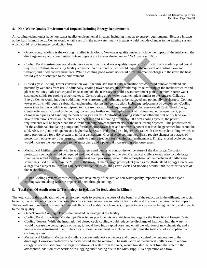
Ameren Missouri-Rush Island Energy Center Fact Sheet Page 39 of 51
4. Non-Water Quality Environmental Impacts Including Energy Requirements All cooling technologies have non-water quality environmental impacts, including impacts to energy requirements. Because impacts at the Rush Island Energy Center would entail a retrofit, the non-water quality impacts would include changes to the existing system, which could result in energy production loss.
• Once-through cooling is the existing installed technology. Non-water quality impacts include the impact of the intake and the
discharge on aquatic communities. Intake impacts are to be evaluated under CWA Section 316(b). • Cooling Pond construction would entail non-water quality and water quality impacts. Construction of a cooling pond would
require retrofitting the existing facility, construction of a pond, which would require the removal of existing farmland, wetland, and flood control structures. While a cooling pond would not entail direct thermal discharges to the river, the heat would yet be discharged to the environment.
• Closed-Cycle Cooling Tower construction would require additional land acquisition which would remove farmland and
potentially wetlands from use. Additionally, cooling tower construction would require retrofitting of the intake structure and plant operations. Other anticipated impacts include the necessity to build a water treatment plant to remove source water suspended solids for cooling tower makeup. Constructing a raw water treatment plant similar to the Ameren Callaway Energy Center would introduce additional waste streams and pollutants to be managed and potentially discharged. Cooling tower retrofits will require substantial engineering, design and construction, including replacement of condensers. Cooling tower installations would be anticipated to increase parasitic load requirements and decrease overall Rush Island Energy Center efficiency. Closed cycle cooling towers may further require replacement of turbines and other equipment, plus changes in piping and handling methods of waste streams. A retrofitted cooling system of either the wet or dry type would have a deleterious effect on the plant’s net heat rate and generating efficiency. If a wet cooling system, the power requirements will be higher than the current pumping power requirements for the once-through system. This power is used for the additional circulating pumps and for the cooling tower fans and represents power that must be generated but cannot be sold. Also, the plant will operate at a higher backpressure and therefore a higher heat rate with closed cycle cooling, which is more pronounced for a dry system than for a wet system. Closed cycle cooling would also require changes in outages of power from once every three years currently to a more frequent for cleaning and maintenance. Finally, closed cycle cooling would increase the heat released to the atmosphere and a potential increase in greenhouse gases.
• Mechanical Chillers operate with heat exchangers and pumps to control the temperature of the discharge. Corrosion
protection chemicals would be required and would entail energy to operate. Mechanical chillers would also include large river water withdrawals and the transfer the heat from processed water to the atmosphere. While mechanical chillers are sometimes used elsewhere in the Midwest, the usage at such a large power plant (such as the Rush Island Energy Center) on a large river subject to Corps of Engineers jurisdiction, fluctuating river levels and flooding would limit the effectiveness of this technology.
• Helper Cooling Systems construction would have many of the similar non-water quality impacts as a full closed cycle
cooling system, along with the impacts of once-through cooling. 5. Total Cost Of Application Of Technology In Relation To Reduction In Effluent The total cost of the application of the technology needs to evaluate the costs of the benefits of the reduction in the effluent, the social benefits, the capital and construction costs, the costs in loss generation and electricity to sale, and the overall environmental impact. The overall environmental cost needs to include the cost of additional chemicals, impacts to waste streams being handled, and impacts to the air quality.
• Once Through Cooling: This is the installed technology at the facility. • Cooling Pond: Space and Mississippi River issues preclude this as a viable technology for the Rush Island Energy Center. • Cooling Towers: While the installation of closed cycle cooling would reduce the discharge of heat load into the water, it
would increase the consumption of water, it would have high capital costs and entail the addition of new chemicals, and a new raw water treatment plant. The costs of these factors must be included to determine the total cost of a complete plant cooling system.
• Mechanical Chillers: Mechanical chillers operate with heat exchangers and pumps to control the temperature of the discharge. Corrosion protection chemicals would also be required. The installation of mechanical chillers would require energy to operate, still have the large withdrawal of water from the river, would transfer the heat from the water to the atmosphere, addition of concerns with clogging and flooding due to the Mississippi River operation and flow.
Ameren Missouri-Rush Island Energy Center Fact Sheet Page 40 of 51
• Helper Cooling Systems: The construction of a helper cooling system would still impact aquatic life via the intake structure,
discharge heated water, require retrofits to the existing system resulting in a loss of energy production, introduce additional chemicals to the process to prevent fouling and scaling, and put more heat into the atmosphere. At the Brayton Point Power Plant, which is 1500 MW plant (approximately 27% larger than the Rush Island Energy Center), the estimated construction cost (2002 dollars) was $98.9 million, with an estimated annual maintenance costs of $300,000 per year. In addition, the Brayton Point Plant estimated combined lost annual generation to be 152,148 MW-hr/year. This consists of 112,875 MW-hr/yr off additional auxiliary power consumption and 39,275 MW-hr/yr of steam turbine operating penalties.7
6. Reasonableness Of The Cost Of The Application Of Technology And The Removal Of Effluent The cooling technologies are established technologies throughout the country; however the construction and establishment of the technology at the Rush Island Energy Center requires a detailed engineering evaluation. The reasonableness of the application of the technology must account for the ability of the technology to be constructed and used on site and to produce a benefit of removing the parameter of concern (heat). The installation of the technology (or a mix thereof) must be a reasonable and logical solution. • Once-through cooling is the established and existing technology at the Rush Island Energy Center. Once-through cooling has impacts on thermal discharge to the Mississippi River and impacts on impingement and entrainment at the intake. While once-through cooling withdraws high volumes of Mississippi River water, it returns nearly all of those withdrawals to the river. • A cooling pond is not a reasonable alternative for the Rush Island Energy Center as the location is not appropriate and the heat would still be discharged to the environment via recirculation through the pond. Suitable adjacent land is largely unavailable; therefore resultant impacts to wetland areas would be significant. • Closed Cycle Cooling Towers are an established technology that may be feasible at the Rush Island Energy Center. Siting conditions must be considered. The installation of closed cycle cooling may reduce the generating capacity of the facility by 4% or more. With closed cycle cooling, more water would be consumed in the process, a raw water treatment plant would need constructed to remove source water suspended solids for cooling tower makeup, and chemicals would be required to prevent fouling and scaling in the towers. Closed cycle cooling may require replacement of turbines and other equipment, plus changes in piping and handling methods of waste streams. Closed cycle cooling would also require changes in generating unit planned maintenance outages from once every three years currently to a more frequent period for cooling tower cleaning and maintenance. Closed cycle cooling would further increase the heat released to the atmosphere and a potential increase in greenhouse gases. • Mechanical Chillers: Mechanical chillers operate with heat exchangers and pumps to control the temperature of the discharge. Corrosion protection chemicals would also be required. The installation of mechanical chillers would require energy to operate, still have the large withdrawal of water from the river, would transfer the heat from the water to the atmosphere, with additional concerns with clogging and flooding due to the Mississippi River’s operation and flow. Concerns cited by the Carroll County, Maryland with using mechanical chillers include air pollution concerns, water quality such as usage of biocides, and noise pollution. • Helper Cooling Systems would have the impacts of both closed cycle cooling system and the existing once through system. While it would reduce the impact of heat into the Mississippi River, it would still require the treatment at the raw water treatment plant, retrofitting of the system to handle at least partial flow through a cooling tower for recirculation. Additional chemicals to prevent fouling and scaling in the tower. Ameren estimates that it would cost approximately $112 million to construct a helper cooling tower for one unit at the Rush Island Energy Center. At Brayton Point, there was a high energy penalty with the installation of a helper cooling tower with the loss of annual generation of 152,148 MW-hr/year.8 As part of the renewal and the 316(b) requirements, changes to the intake structure are required and one option required for evaluation is the installation of closed cycle cooling. 7. Comparison Of Cost And Level Of Reduction • Once-through cooling is the existing technology in use. This is what the Rush Island Energy Center was designed to utilize and the cost to continue operating and maintaining the system is negligible. The ported mid-channel cooling water discharge ensures rapid mixing of the thermal effluent and ensures that the mixing zone is small. Under the final existing facilities 316(b) intake structure rule, technology and/or operational revisions could be required to reduce the number of aquatic larval and fish being impinged and entrained via the intake structure.
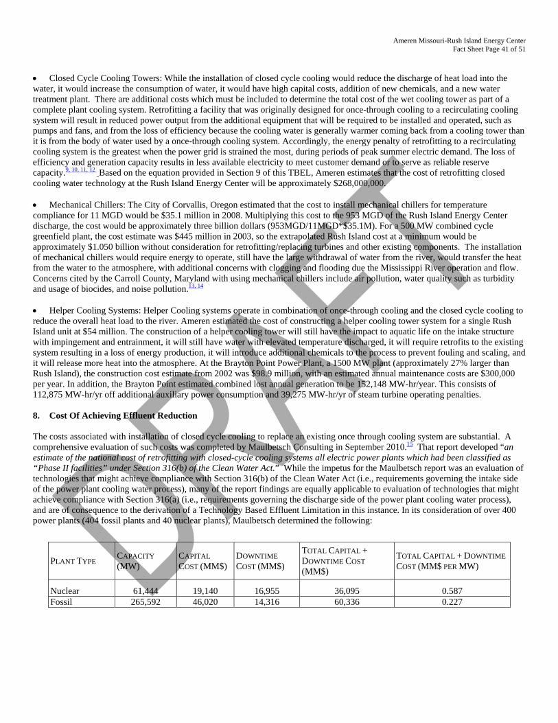
Ameren Missouri-Rush Island Energy Center Fact Sheet Page 41 of 51
• Closed Cycle Cooling Towers: While the installation of closed cycle cooling would reduce the discharge of heat load into the water, it would increase the consumption of water, it would have high capital costs, addition of new chemicals, and a new water treatment plant. There are additional costs which must be included to determine the total cost of the wet cooling tower as part of a complete plant cooling system. Retrofitting a facility that was originally designed for once-through cooling to a recirculating cooling system will result in reduced power output from the additional equipment that will be required to be installed and operated, such as pumps and fans, and from the loss of efficiency because the cooling water is generally warmer coming back from a cooling tower than it is from the body of water used by a once-through cooling system. Accordingly, the energy penalty of retrofitting to a recirculating cooling system is the greatest when the power grid is strained the most, during periods of peak summer electric demand. The loss of efficiency and generation capacity results in less available electricity to meet customer demand or to serve as reliable reserve capacity.9, 10, 11, 12 Based on the equation provided in Section 9 of this TBEL, Ameren estimates that the cost of retrofitting closed cooling water technology at the Rush Island Energy Center will be approximately $268,000,000. • Mechanical Chillers: The City of Corvallis, Oregon estimated that the cost to install mechanical chillers for temperature compliance for 11 MGD would be $35.1 million in 2008. Multiplying this cost to the 953 MGD of the Rush Island Energy Center discharge, the cost would be approximately three billion dollars (953MGD/11MGD*$35.1M). For a 500 MW combined cycle greenfield plant, the cost estimate was $445 million in 2003, so the extrapolated Rush Island cost at a minimum would be approximately $1.050 billion without consideration for retrofitting/replacing turbines and other existing components. The installation of mechanical chillers would require energy to operate, still have the large withdrawal of water from the river, would transfer the heat from the water to the atmosphere, with additional concerns with clogging and flooding due the Mississippi River operation and flow. Concerns cited by the Carroll County, Maryland with using mechanical chillers include air pollution, water quality such as turbidity and usage of biocides, and noise pollution.13, 14 • Helper Cooling Systems: Helper Cooling systems operate in combination of once-through cooling and the closed cycle cooling to reduce the overall heat load to the river. Ameren estimated the cost of constructing a helper cooling tower system for a single Rush Island unit at $54 million. The construction of a helper cooling tower will still have the impact to aquatic life on the intake structure with impingement and entrainment, it will still have water with elevated temperature discharged, it will require retrofits to the existing system resulting in a loss of energy production, it will introduce additional chemicals to the process to prevent fouling and scaling, and it will release more heat into the atmosphere. At the Brayton Point Power Plant, a 1500 MW plant (approximately 27% larger than Rush Island), the construction cost estimate from 2002 was $98.9 million, with an estimated annual maintenance costs are $300,000 per year. In addition, the Brayton Point estimated combined lost annual generation to be 152,148 MW-hr/year. This consists of 112,875 MW-hr/yr off additional auxiliary power consumption and 39,275 MW-hr/yr of steam turbine operating penalties. 8. Cost Of Achieving Effluent Reduction The costs associated with installation of closed cycle cooling to replace an existing once through cooling system are substantial. A comprehensive evaluation of such costs was completed by Maulbetsch Consulting in September 2010.15 That report developed “an estimate of the national cost of retrofitting with closed-cycle cooling systems all electric power plants which had been classified as “Phase II facilities” under Section 316(b) of the Clean Water Act.” While the impetus for the Maulbetsch report was an evaluation of technologies that might achieve compliance with Section 316(b) of the Clean Water Act (i.e., requirements governing the intake side of the power plant cooling water process), many of the report findings are equally applicable to evaluation of technologies that might achieve compliance with Section 316(a) (i.e., requirements governing the discharge side of the power plant cooling water process), and are of consequence to the derivation of a Technology Based Effluent Limitation in this instance. In its consideration of over 400 power plants (404 fossil plants and 40 nuclear plants), Maulbetsch determined the following:
PLANT TYPE CAPACITY (MW)
CAPITAL COST (MM$)
DOWNTIME COST (MM$)
TOTAL CAPITAL + DOWNTIME COST (MM$)
TOTAL CAPITAL + DOWNTIME COST (MM$ PER MW)
Nuclear 61,444 19,140 16,955 36,095 0.587 Fossil 265,592 46,020 14,316 60,336 0.227
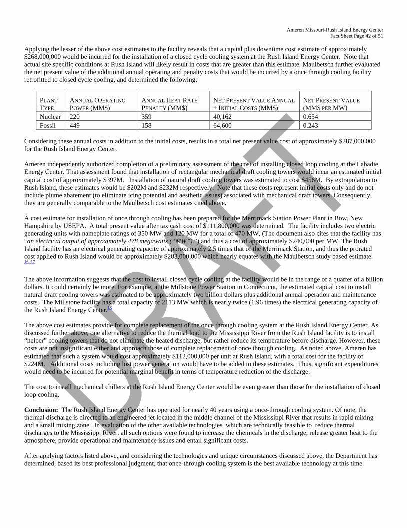
Ameren Missouri-Rush Island Energy Center Fact Sheet Page 42 of 51
Applying the lesser of the above cost estimates to the facility reveals that a capital plus downtime cost estimate of approximately $268,000,000 would be incurred for the installation of a closed cycle cooling system at the Rush Island Energy Center. Note that actual site specific conditions at Rush Island will likely result in costs that are greater than this estimate. Maulbetsch further evaluated the net present value of the additional annual operating and penalty costs that would be incurred by a once through cooling facility retrofitted to closed cycle cooling, and determined the following:
PLANT TYPE
ANNUAL OPERATING POWER (MM$)
ANNUAL HEAT RATE PENALTY (MM$)
NET PRESENT VALUE ANNUAL + INITIAL COSTS (MM$)
NET PRESENT VALUE (MM$ PER MW)
Nuclear 220 359 40,162 0.654 Fossil 449 158 64,600 0.243
Considering these annual costs in addition to the initial costs, results in a total net present value cost of approximately $287,000,000 for the Rush Island Energy Center. Ameren independently authorized completion of a preliminary assessment of the cost of installing closed loop cooling at the Labadie Energy Center. That assessment found that installation of rectangular mechanical draft cooling towers would incur an estimated initial capital cost of approximately $397M. Installation of natural draft cooling towers was estimated to cost $456M. By extrapolation to Rush Island, these estimates would be $202M and $232M respectively. Note that these costs represent initial costs only and do not include plume abatement (to eliminate icing potential and aesthetic issues) associated with mechanical draft towers. Consequently, they are generally comparable to the Maulbetsch cost estimates cited above. A cost estimate for installation of once through cooling has been prepared for the Merrimack Station Power Plant in Bow, New Hampshire by USEPA. A total present value after tax cash cost of $111,800,000 was determined. The facility includes two electric generating units with nameplate ratings of 350 MW and 120 MW for a total of 470 MW, (The document also cites that the facility has “an electrical output of approximately 478 megawatts (“MW”).”) and thus a cost of approximately $240,000 per MW. The Rush Island facility has an electrical generating capacity of approximately 2.5 times that of the Merrimack Station, and thus the prorated cost applied to Rush Island would be approximately $283,000,000 which nearly equates with the Maulbetsch study based estimate. 16, 17 The above information suggests that the cost to install closed cycle cooling at the facility would be in the range of a quarter of a billion dollars. It could certainly be more. For example, at the Millstone Power Station in Connecticut, the estimated capital cost to install natural draft cooling towers was estimated to be approximately two billion dollars plus additional annual operation and maintenance costs. The Millstone facility has a total capacity of 2113 MW which is nearly twice (1.96 times) the electrical generating capacity of the Rush Island Energy Center.18 The above cost estimates provide for complete replacement of the once through cooling system at the Rush Island Energy Center. As discussed further above, one alternative to reduce the thermal load to the Mississippi River from the Rush Island facility is to install “helper” cooling towers that do not eliminate the heated discharge, but rather reduce its temperature before discharge. However, these costs are not insignificant either and approach those of complete replacement of once through cooling. As noted above, Ameren has estimated that such a system would cost approximately $112,000,000 per unit at Rush Island, with a total cost for the facility of $224M. Additional costs including lost power generation would have to be added to these estimates. Thus, significant expenditures would need to be incurred for potential marginal benefit in terms of temperature reduction of the discharge. The cost to install mechanical chillers at the Rush Island Energy Center would be even greater than those for the installation of closed loop cooling. Conclusion: The Rush Island Energy Center has operated for nearly 40 years using a once-through cooling system. Of note, the thermal discharge is directed to an engineered jet located in the middle channel of the Mississippi River that results in rapid mixing and a small mixing zone. In evaluation of the other available technologies which are technically feasible to reduce thermal discharges to the Mississippi River, all such options were found to increase the chemicals in the discharge, release greater heat to the atmosphere, provide operational and maintenance issues and entail significant costs.
After applying factors listed above, and considering the technologies and unique circumstances discussed above, the Department has determined, based its best professional judgment, that once-through cooling system is the best available technology at this time.
Ameren Missouri-Rush Island Energy Center Fact Sheet Page 43 of 51
References: 1. Hensley, John. Cooling Tower Fundamentals at p. 86.
http://spxcooling.com/pdf/Cooling-Tower-Fundamentals.pdf 2. Cooling Pond. BrightHub Engineering.
http://www.brighthubengineering.com/power-plants/66493-cooling-pond-or-wetlands-for-thermal-power-plant-condenser-cooling/
3. Hensley, John. Cooling Tower Fundamentals at p. 86. http://spxcooling.com/pdf/Cooling-Tower-Fundamentals.pdf
4. Cooley, Heather. Pacific Institute. Water for Energy: Future Water Needs for Electricity in the Intermountain West. November 2011. http://www.pacinst.org/wp-content/uploads/2013/02/water_for_energy3.pdf
5. Hybrid Wet and Dry Cooling. BrightHub Engineering. http://www.brighthubengineering.com/power-plants/66087-steam-power-plant-condenser-cooling-hybrid-wet-and-dry-cooling/
6. Hensley, John. Cooling Tower Fundamentals at p. 86. http://spxcooling.com/pdf/Cooling-Tower-Fundamentals.pdf
7. Ameren Integrated Resource Plan Section 5. https://www.ameren.com/missouri/environment/renewables/ameren-missouri-irp 8. Ameren Integrated Resource Plan Section 5. (https://www.ameren.com/missouri/environment/renewables/ameren-missouri-irp 9. Wheeler, Brian. Power Engineering: Retrofit Options to Comply with 316(b). 10/01/2010.
http://www.power-eng.com/articles/print/volume-114/issue-10/features/retrofit-options-to-comply-with-316-b.html 10. Bailey, D. EPRI. Issues Analysis of Retrofitting Once-Through Cooled Plants with Closed-Cycle Cooling, TR-052907, October
2007. http://www.waterboards.ca.gov/water_issues/programs/ocean/cwa316/docs/epri_retrofit_otc.pdf
11. Corvallis Oregon Conclusions and Recommendations for WWRP discharge. https://www.corvallisoregon.gov/modules/showdocument.aspx?documentid=496
12. US Department of Energy. Electricity Reliability Impacts of a Mandatory Cooling Tower Rule for Existing Steam Generation Units. October 2008. http://www.netl.doe.gov/energy-analyses/pubs/Cooling_Tower_Report.pdf
13. PowerGen International 2003 Comparison of Power Enhancement Options for Greenfield Combined Cycle Power Plants. http://www.tas.com/sites/default/files/comparison-of-power-enhancement-options-for-greenfield-combined-cycle-power-plants.pdf
14. Brayton Point NPDES Factsheet Chapter 4: TBEL Determination. http://www.epa.gov/region1/npdes/braytonpoint/pdfs/BRAYTONchapter4.PDF
15. Closed-Cycle Retrofitting Study: Capital and Performance Cost Estimates, prepared by Maulbetsch Consulting for EPRI (Palo Alto, CA) et al., Final Report September 2010.
16. New England Clean Water Act NPDES Permitting Determinations for the Thermal Discharge and Cooling Water Intake Structures at Merrimack Station in Bow, New Hampshire, NPDES Permit No. NH0001465.
17. Attachment D to 2011 Fact Sheet for Draft NPDES permit, prepared by USEPA New England Region I, September 27, 2011. 18. Comprehensive Evaluation of Cooling Water System Alternatives at Millstone Power Station (MPS) Final Report, Project No.
19998242.10400, prepared by URS, August 2012.
Ameren Missouri-Rush Island Energy Center Fact Sheet Page 44 of 51
CONVENTIONAL POLLUTANTS: For the purposes of permit renewal, several conventional parameters were sampled. The facility reported biochemical oxygen demand at 4 mg/L. The facility reported chemical oxygen demand at 22 mg/L. The facility reported total organic carbon at 6.6 mg/L. The facility reported Oil and Grease at 2.2 mg/L. The facility reported total suspended solids at 178 mg/L. The permit writer has determined none of the above pollutants are of concern at this outfall. The Mississippi River is inherently turbid and while the once-through cooling water system condenses the water, the concentration of additional solids is negligible. The facility reported total residual chlorine was believed absent. However, the ELG identifies once-thorough cooling water as subject to BPT and BAT regulations for chlorine.
pH 6.0 to 9.0 SU. The Water Quality Standard at 10 CSR 20-7.031(5)(E) states water contaminants shall not cause pH to be outside the range of 6.0 to 9.0 standard pH units. Chlorine, Free Available The facility is limited per the ELG at 40 CFR 423.12 for best practicable control technology (BPT) of once through cooling water at 0.5 mg/L daily maximum, and 0.2 mg/L monthly average concentration. The facility is not afforded a schedule of compliance because the EPA has promulgated the ELG and these conditions are subject to all applicable facilities at all times. The facility has stated they infrequently use chlorine as a biocide. The department has considered and approved an “unscheduled” sampling regime.
Chlorine, Total Recoverable The facility is limited per the ELG at 40 CFR 423.13 for best available technology (BAT) of once through cooling water at 0.2 mg/L daily maximum concentration. The facility is not afforded a schedule of compliance because the EPA has promulgated the ELG and these conditions are subject to all applicable facilities at all times. The facility has stated they infrequently use chlorine as a biocide. The department has considered and approved an “unscheduled” sampling regime.
METALS: The facility reported any metals found in the once-through cooling water discharge are already present in the river. The permit writer has determined no additional testing of any metals is required at this outfall at this time. NUTRIENTS: The facility reported any nutrients found in the once-through cooling water discharge are already present in the river. The permit writer has determined no additional testing of nutrients at this outfall is required at this time.
OTHER: The facility reported any bromide, Dioxin, fluoride, radioactivity, sulfate, sulfide, sulfite, or surfactants found in the once-through cooling water discharge are already present in the river. The permit writer has determined no additional testing of these parameters is needed at this outfall at this time.
WET Test, Acute Previous permit limitations were pass/fail; however the department cannot perform RPA on narrative data. The permit writer has determined several biocides including chlorine may be used on the cooling tower therefore WET monitoring is required when the biocides are in use. See Part VII Administrative Requirements, Public Notice Comments. For classified permanent streams, the Allowable Effluent Concentration (AEC)% is determined as follows: Acute AEC% = [DFcfs ÷ (ZID7Q10 + DFcfs)] x 100% = ## % Acute AEC% = [1121 CFS ÷ (585 + 1121 CFS)] x 100% = 65.7% ≈ 66% 10 CSR 20-7.015((9)(L)4.A. states the dilution series must be proportional. Each dilution was determined by multiplying or dividing 0.8 from the AEC and then each consecutive value. The calculated dilution series for this facility is: 83%, 66%, 53%, 42%, and 34%.
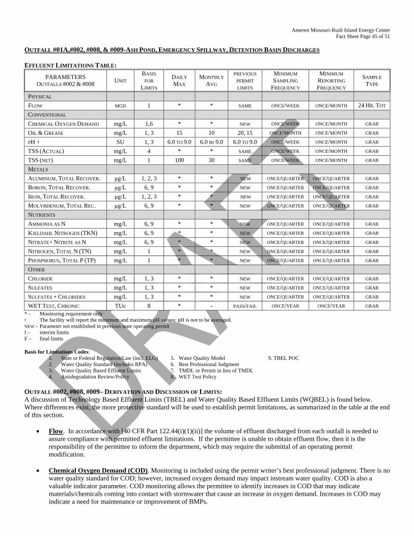
Ameren Missouri-Rush Island Energy Center Fact Sheet Page 45 of 51
OUTFALL #01A,#002, #008, & #009-ASH POND, EMERGENCY SPILLWAY, DETENTION BASIN DISCHARGES EFFLUENT LIMITATIONS TABLE:
PARAMETERS OUTFALLS #002 & #008 UNIT
BASIS FOR
LIMITS
DAILY MAX
MONTHLY AVG
PREVIOUS PERMIT LIMITS
MINIMUM SAMPLING
FREQUENCY
MINIMUM REPORTING FREQUENCY
SAMPLE TYPE
PHYSICAL FLOW MGD 1 * * SAME ONCE/WEEK ONCE/MONTH 24 HR. TOT CONVENTIONAL CHEMICAL OXYGEN DEMAND mg/L 1,6 * * NEW ONCE/WEEK ONCE/MONTH GRAB OIL & GREASE mg/L 1, 3 15 10 20, 15 ONCE/MONTH ONCE/MONTH GRAB PH ǂ SU 1, 3 6.0 TO 9.0 6.0 to 9.0 6.0 TO 9.0 ONCE/WEEK ONCE/MONTH GRAB TSS (ACTUAL) mg/L 4 * * SAME ONCE/WEEK ONCE/MONTH GRAB TSS (NET) mg/L 1 100 30 SAME ONCE/WEEK ONCE/MONTH GRAB METALS ALUMINUM, TOTAL RECOVER. μg/L 1, 2, 3 * * NEW ONCE/QUARTER ONCE/QUARTER GRAB BORON, TOTAL RECOVER. μg/L 6, 9 * * NEW ONCE/QUARTER ONCE/QUARTER GRAB IRON, TOTAL RECOVER. μg/L 1, 2, 3 * * NEW ONCE/QUARTER ONCE/QUARTER GRAB MOLYBDENUM, TOTAL REC. μg/L 6, 9 * * NEW ONCE/QUARTER ONCE/QUARTER GRAB NUTRIENTS AMMONIA AS N mg/L 6, 9 * * NEW ONCE/QUARTER ONCE/QUARTER GRAB KJELDAHL NITROGEN (TKN) mg/L 6, 9 * * NEW ONCE/QUARTER ONCE/QUARTER GRAB NITRATE+ NITRITE AS N mg/L 6, 9 * * NEW ONCE/QUARTER ONCE/QUARTER GRAB NITROGEN, TOTAL N (TN) mg/L 1 * * NEW ONCE/QUARTER ONCE/QUARTER GRAB PHOSPHORUS, TOTAL P (TP) mg/L 1 * * NEW ONCE/QUARTER ONCE/QUARTER GRAB OTHER CHLORIDE mg/L 1, 3 * * NEW ONCE/QUARTER ONCE/QUARTER GRAB SULFATES mg/L 1, 3 * * NEW ONCE/QUARTER ONCE/QUARTER GRAB SULFATES + CHLORIDES mg/L 1, 3 * * NEW ONCE/QUARTER ONCE/QUARTER GRAB WET TEST, CHRONIC TUc 8 * - PASS/FAIL ONCE/YEAR ONCE/YEAR GRAB
* - Monitoring requirement only ǂ The facility will report the minimum and maximum pH values; pH is not to be averaged. NEW - Parameter not established in previous state operating permit I – interim limits F – final limits Basis for Limitations Codes:
1. State or Federal Regulation/Law (incl. ELG) 5. Water Quality Model 9. TBEL POC 2. Water Quality Standard (includes RPA) 6. Best Professional Judgment 3. Water Quality Based Effluent Limits 7. TMDL or Permit in lieu of TMDL 4. Antidegradation Review/Policy 8. WET Test Policy
OUTFALL #002, #008, #009– DERIVATION AND DISCUSSION OF LIMITS: A discussion of Technology Based Effluent Limits (TBEL) and Water Quality Based Effluent Limits (WQBEL) is found below. Where differences exist, the more protective standard will be used to establish permit limitations, as summarized in the table at the end of this section.
• Flow. In accordance with [40 CFR Part 122.44(i)(1)(ii)] the volume of effluent discharged from each outfall is needed to assure compliance with permitted effluent limitations. If the permittee is unable to obtain effluent flow, then it is the responsibility of the permittee to inform the department, which may require the submittal of an operating permit modification.
• Chemical Oxygen Demand (COD). Monitoring is included using the permit writer’s best professional judgment. There is no
water quality standard for COD; however, increased oxygen demand may impact instream water quality. COD is also a valuable indicator parameter. COD monitoring allows the permittee to identify increases in COD that may indicate materials/chemicals coming into contact with stormwater that cause an increase in oxygen demand. Increases in COD may indicate a need for maintenance or improvement of BMPs.
Ameren Missouri-Rush Island Energy Center Fact Sheet Page 46 of 51
• Total Suspended Solids (Intake, Net, & Gross). Due to the fact that there are several sources with differing flows subject to different ELGs, effluent limitations for TSS will be established in concentration (mg/L) rather than mass (lb/day), in accordance with 40 CFR 423.12(b)(11). Additionally, TSS is to be reported as a net and/or gross limit in accordance with 40 CFR 122.45(g). Therefore, TSS limits are 100 mg/L as a Daily Maximum and 30 mg/L as a Monthly Average, in accordance with 40 CFR 423.12(b)(3) and (4). The following conditions apply to TSS limits for determining compliance with regards to credit for TSS from intake waters.
1. Only water withdrawn from the Missouri River that is used for process (e.g., fly ash transport) water and
discharged to the Missouri River is to be used in calculating the net discharge of TSS. Credit for TSS from other sources of water (including rainwater) can not be used for credit.
2. Credit may be taken only to the extent necessary to meet effluent limits. 3. The maximum credit may not exceed the concentration in the intake water 4. All measures for flow and TSS must be made the same day. Net discharge is to be calculated as follows: (Qd x 8.34 x Cd) – (Qr x 8.34 x Cr) / (Qd x 8.34) = Net discharge in mg/L Where: Qd = Flow from Outfall #002 (in MGD) that was withdrawn from the Missouri River; Cd = Concentration of TSS measure in the final effluent from Outfall #002 in mg/L; Qr = Intake flow (in MGD) that flows to Outfall #002 ; Cr = Intake flow TSS concentration. When taking credit for TSS in the intake water, the permittee will be required to document all measurements and calculations used to determine the amount of the credit and shall report the gross and the net discharge of TSS on the discharge monitoring report. Therefore, TSS intake and gross are required to have monitoring conditions only. The TSS Net discharge shall never be less than 0 mg/L.
• pH. In accordance with 40 CFR 423.12(b)(1), pH shall be maintained in the range of 6.0 – 9.0. In accordance with 10 CSR 20-
7.031(4)(E), pH shall be maintained in the range of 6.5 – 9.0 pH SU, and pH is not to be averaged. DMRs for the past 5 years were reviewed and document that this facility can meet the new more protective limits. Therefore, pH limitation range will be applicable upon issuance of this operating permit
• Oil & Grease. Due to the fact that there are several sources with differing flows subject to different ELGs, effluent
limitations for Oil and Grease will be established in concentration (mg/L) rather than mass (lb/day), in accordance with 40 CFR 423.12(b)(11). 20 mg/L as a Daily Maximum and 15 mg/L as a Monthly Average in accordance with 40 CFR 423.12(b)(3) & (4). The water quality standard for the protection of aquatic life; 10 mg/L monthly average, 15 mg/L daily maximum. DMRs for the past 5 years were reviewed and document that this facility can meet the new more protective limits. Therefore, O&G limits will be applicable upon issuance of this operating permit.
• Technology-based Effluent Limit versus Water Quality-based Effluent Limit
Limitations in bold signify they are more protective and will be established as a permit limit.
Pollutant TBEL (40 CFR 423) WQBEL (10 CSR 20-7.031) Daily Maximum Monthly Average Daily Maximum Monthly Average
TSS 100 mg/L 30 mg/L N/A N/A pH 6.0 – 9.0 6.0 – 9.0 6.5 – 9.0 6.5 – 9.0
Oil & Grease 20 15 15 10 METALS:
• Aluminum, Total Recoverable. Aluminum is a parameter of concern for the industry. In evaluating the expanded test results for
Outfall 002 and comparing with the background concentration, quarterly monitoring only is being required for this permit. • Boron, Total Recoverable. Boron is a parameter of concern for the industry. The irrigation use limitations are 2,000 µg/L. In
evaluating the expanded test results for Outfall 002 and comparing with the background concentration and the technology based effluent limit determination, quarterly monitoring only is being required for this permit.
• Iron, Total Recoverable. Aluminum is a parameter of concern for the industry. In evaluating the expanded test results for Outfall 002 and comparing with the background concentration, quarterly monitoring only is being required for this permit.
• Molybdenum, Total Recoverable. Molybdenum is a parameter of concern for the industry. Quarterly monitoring is required.
Ameren Missouri-Rush Island Energy Center Fact Sheet Page 47 of 51
NUTRIENTS:
Ammonia, Total as Nitrogen. Monitoring only, as Outfall #003 discharges into Outfall #002 and in the expanded effluent testing, ammonia was present in the discharge. Quarterly basis.
Kjeldahl Nitrogen, Total (TKN) Added using the permit writer’s best professional judgment. TKN is the sum of ammonia-nitrogen plus organically bound nitrogen but does not include nitrate-nitrogen or nitrite-nitrogen. The department is asking the facility to also provide this data. Nitrate plus Nitrite as Nitrogen The TBEL evaluation has determined nitrate plus nitrite as N is a pollutant of concern for the facility. The facility reported 0.4 mg/L at Outfall #002, and 3.6 mg/L at Outfall #003. Nitrogen, Total N (TN) Total Nitrogen (TN) is the sum of nitrate-nitrogen (NO3-N), nitrite-nitrogen (NO2-N), ammonia-nitrogen (NH3-N) and organically bonded nitrogen. Per 10 CSR 20-7.015(9)(D)7, nutrient monitoring shall be instituted on a quarterly basis for facilities with a design flow greater than 0.1 MGD. Phosphorous, Total P (TP) Per 10 CSR 20-7.015(9)(D)7, nutrient monitoring shall be instituted on a quarterly basis for facilities with a design flow greater than 0.1 MGD.
OTHER: Chloride
Missouri has proposed a state water quality standards change since the previous permit was issued. In the proposed standard, the sulfate standard for protection of aquatic life is dependent on the hardness and the chloride concentration.
Sulfates The facility reported 520 mg/L sulfate in the application for permit renewal. The drinking water standard for sulfate is 250 mg/L. Monitoring only. Sulfate is a parameter of concern in coal ash; quarterly monitoring is required.
Chlorides plus Sulfates The facility will sample chloride and sulfate individually and provide the sum to the department quarterly.
Whole Effluent Toxicity (WET) Test, Chronic For Outfalls #01A and #002, Monitoring is required to determine if reasonable potential exists for the discharge to cause toxicity within the receiving stream. For classified permanent streams with other than default mixing considerations, the Allowable Effluent Concentration (AEC)% is determined as follows: Chronic AEC% = [DFcfs ÷ (MZ7Q10 + DFcfs)] x 100% = ##% Acute AEC% = ((design flowcfs + ZID7Q10) / design flowcfs)-1] x 100 = ##% Acute AEC% = ((66.8 + 668) / 66.8)-1] x 100 = 9.1% rounded up to 10%
Dilution series is as follows: 80%, 40%, 20%, 10%, and 5%. OUTFALL #003 – WASTEWATER TREATMENT PLANT Effluent limitations derived and established in the below Effluent Limitations Table are based on current operations of the facility. Future permit action due to facility modification may contain new operating permit terms and conditions that supersede the terms and conditions, including effluent limitations, of this operating permit.
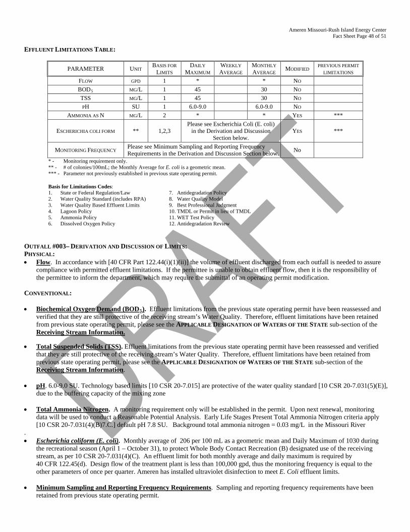
Ameren Missouri-Rush Island Energy Center Fact Sheet Page 48 of 51
EFFLUENT LIMITATIONS TABLE:
PARAMETER UNIT BASIS FOR LIMITS
DAILY MAXIMUM
WEEKLY AVERAGE
MONTHLY AVERAGE MODIFIED PREVIOUS PERMIT
LIMITATIONS FLOW GPD 1 * * NO BOD5 MG/L 1 45 30 NO TSS MG/L 1 45 30 NO PH SU 1 6.0-9.0 6.0-9.0 NO
AMMONIA AS N MG/L 2 * * YES ***
ESCHERICHIA COLI FORM ** 1,2,3 Please see Escherichia Coli (E. coli)
in the Derivation and Discussion Section below.
YES ***
MONITORING FREQUENCY Please see Minimum Sampling and Reporting Frequency Requirements in the Derivation and Discussion Section below. No
* - Monitoring requirement only. ** - # of colonies/100mL; the Monthly Average for E. coli is a geometric mean. *** - Parameter not previously established in previous state operating permit.
Basis for Limitations Codes: 1. State or Federal Regulation/Law 7. Antidegradation Policy 2. Water Quality Standard (includes RPA) 8. Water Quality Model 3. Water Quality Based Effluent Limits 9. Best Professional Judgment 4. Lagoon Policy 10. TMDL or Permit in lieu of TMDL 5. Ammonia Policy 11. WET Test Policy 6. Dissolved Oxygen Policy 12. Antidegradation Review
OUTFALL #003– DERIVATION AND DISCUSSION OF LIMITS: PHYSICAL: • Flow. In accordance with [40 CFR Part 122.44(i)(1)(ii)] the volume of effluent discharged from each outfall is needed to assure
compliance with permitted effluent limitations. If the permittee is unable to obtain effluent flow, then it is the responsibility of the permittee to inform the department, which may require the submittal of an operating permit modification.
CONVENTIONAL: • Biochemical Oxygen Demand (BOD5). Effluent limitations from the previous state operating permit have been reassessed and
verified that they are still protective of the receiving stream’s Water Quality. Therefore, effluent limitations have been retained from previous state operating permit, please see the APPLICABLE DESIGNATION OF WATERS OF THE STATE sub-section of the Receiving Stream Information.
• Total Suspended Solids (TSS). Effluent limitations from the previous state operating permit have been reassessed and verified
that they are still protective of the receiving stream’s Water Quality. Therefore, effluent limitations have been retained from previous state operating permit, please see the APPLICABLE DESIGNATION OF WATERS OF THE STATE sub-section of the Receiving Stream Information.
• pH. 6.0-9.0 SU. Technology based limits [10 CSR 20-7.015] are protective of the water quality standard [10 CSR 20-7.031(5)(E)],
due to the buffering capacity of the mixing zone • Total Ammonia Nitrogen. A monitoring requirement only will be established in the permit. Upon next renewal, monitoring
data will be used to conduct a Reasonable Potential Analysis. Early Life Stages Present Total Ammonia Nitrogen criteria apply [10 CSR 20-7.031(4)(B)7.C.] default pH 7.8 SU. Background total ammonia nitrogen = 0.03 mg/L in the Missouri River
. • Escherichia coliform (E. coli). Monthly average of 206 per 100 mL as a geometric mean and Daily Maximum of 1030 during
the recreational season (April 1 – October 31), to protect Whole Body Contact Recreation (B) designated use of the receiving stream, as per 10 CSR 20-7.031(4)(C). An effluent limit for both monthly average and daily maximum is required by 40 CFR 122.45(d). Design flow of the treatment plant is less than 100,000 gpd, thus the monitoring frequency is equal to the other parameters of once per quarter. Ameren has installed ultraviolet disinfection to meet E. Coli effluent limits.
• Minimum Sampling and Reporting Frequency Requirements. Sampling and reporting frequency requirements have been
retained from previous state operating permit.
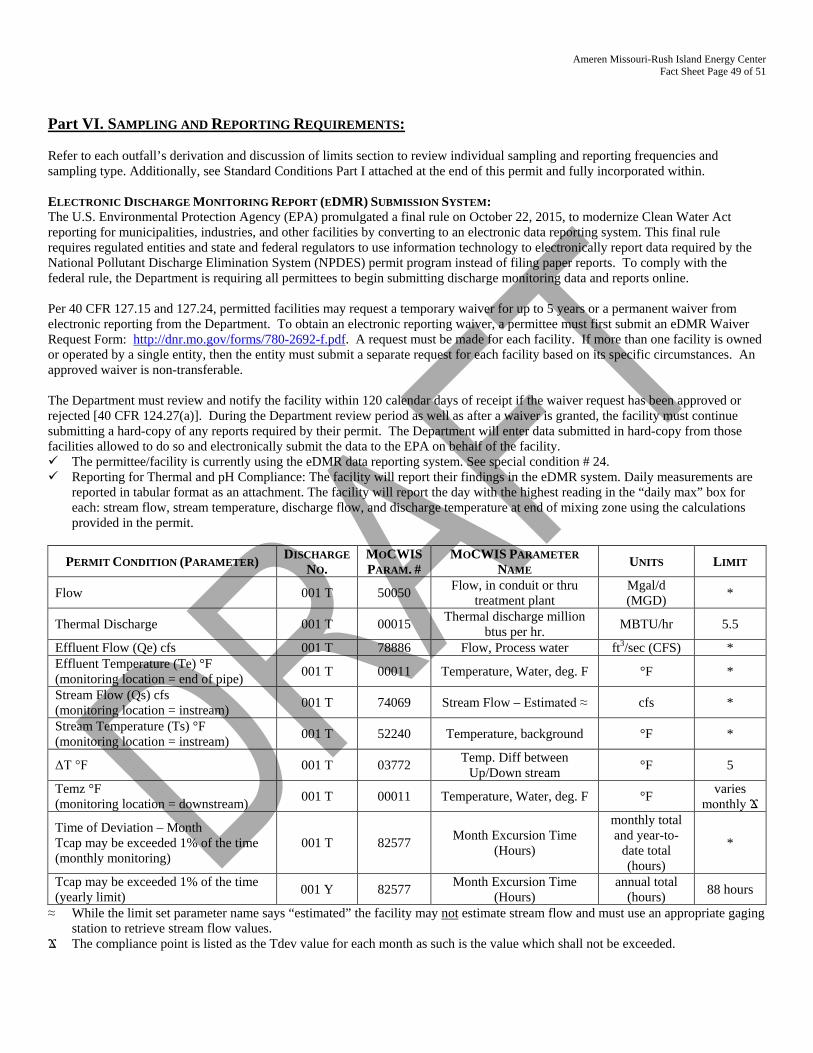
Ameren Missouri-Rush Island Energy Center Fact Sheet Page 49 of 51
Part VI. SAMPLING AND REPORTING REQUIREMENTS: Refer to each outfall’s derivation and discussion of limits section to review individual sampling and reporting frequencies and sampling type. Additionally, see Standard Conditions Part I attached at the end of this permit and fully incorporated within. ELECTRONIC DISCHARGE MONITORING REPORT (EDMR) SUBMISSION SYSTEM: The U.S. Environmental Protection Agency (EPA) promulgated a final rule on October 22, 2015, to modernize Clean Water Act reporting for municipalities, industries, and other facilities by converting to an electronic data reporting system. This final rule requires regulated entities and state and federal regulators to use information technology to electronically report data required by the National Pollutant Discharge Elimination System (NPDES) permit program instead of filing paper reports. To comply with the federal rule, the Department is requiring all permittees to begin submitting discharge monitoring data and reports online. Per 40 CFR 127.15 and 127.24, permitted facilities may request a temporary waiver for up to 5 years or a permanent waiver from electronic reporting from the Department. To obtain an electronic reporting waiver, a permittee must first submit an eDMR Waiver Request Form: http://dnr.mo.gov/forms/780-2692-f.pdf. A request must be made for each facility. If more than one facility is owned or operated by a single entity, then the entity must submit a separate request for each facility based on its specific circumstances. An approved waiver is non-transferable. The Department must review and notify the facility within 120 calendar days of receipt if the waiver request has been approved or rejected [40 CFR 124.27(a)]. During the Department review period as well as after a waiver is granted, the facility must continue submitting a hard-copy of any reports required by their permit. The Department will enter data submitted in hard-copy from those facilities allowed to do so and electronically submit the data to the EPA on behalf of the facility. The permittee/facility is currently using the eDMR data reporting system. See special condition # 24. Reporting for Thermal and pH Compliance: The facility will report their findings in the eDMR system. Daily measurements are
reported in tabular format as an attachment. The facility will report the day with the highest reading in the “daily max” box for each: stream flow, stream temperature, discharge flow, and discharge temperature at end of mixing zone using the calculations provided in the permit.
PERMIT CONDITION (PARAMETER) DISCHARGE NO.
MOCWIS PARAM. #
MOCWIS PARAMETER NAME UNITS LIMIT
Flow 001 T 50050 Flow, in conduit or thru treatment plant
Mgal/d (MGD) *
Thermal Discharge 001 T 00015 Thermal discharge million btus per hr. MBTU/hr 5.5
Effluent Flow (Qe) cfs 001 T 78886 Flow, Process water ft3/sec (CFS) * Effluent Temperature (Te) °F (monitoring location = end of pipe) 001 T 00011 Temperature, Water, deg. F °F *
Stream Flow (Qs) cfs (monitoring location = instream) 001 T 74069 Stream Flow – Estimated ≈ cfs *
Stream Temperature (Ts) °F (monitoring location = instream) 001 T 52240 Temperature, background °F *
ΔT °F 001 T 03772 Temp. Diff between Up/Down stream °F 5
Temz °F (monitoring location = downstream) 001 T 00011 Temperature, Water, deg. F °F varies
monthly Ϫ
Time of Deviation – Month Tcap may be exceeded 1% of the time (monthly monitoring)
001 T 82577 Month Excursion Time (Hours)
monthly total and year-to-
date total (hours)
*
Tcap may be exceeded 1% of the time (yearly limit) 001 Y 82577 Month Excursion Time
(Hours) annual total
(hours) 88 hours
≈ While the limit set parameter name says “estimated” the facility may not estimate stream flow and must use an appropriate gaging station to retrieve stream flow values.
Ϫ The compliance point is listed as the Tdev value for each month as such is the value which shall not be exceeded.
Ameren Missouri-Rush Island Energy Center Fact Sheet Page 50 of 51
SAMPLING FREQUENCY JUSTIFICATION: Sampling and reporting frequency was generally retained from previous permit. Daily sampling of thermal discharge is required to coincide with other similar facilities. This facility is sampling for newly identified contaminants of concern at the ash ponds therefore monthly sampling is required to determine if the facility will be in compliance with the operating permit in accordance with Appendix U of Missouri’s Water Pollution Control Permit Manual. Sampling frequency for stormwater-only outfalls is typically quarterly even though BMP inspection occurs monthly. The facility may sample more frequently if they need additional data to determine if their best management practices or technology is performing as expected. 40 CFR 122.45(d)(1) indicates all continuous discharges shall be permitted with daily maximum and monthly average limits. WET Testing schedules and intervals are established in accordance with the department’s Permit Writers Manual; Section 5.2 Effluent Limits/ WET Testing for Compliance Bio-monitoring.
Chronic Whole Effluent Toxicity
- No less than Once/Year: -Industrial dischargers with toxic parameters in the discharge; which may alter production processes; or facilities which handle
large quantities of toxic substances or substances which are toxic in large amounts shall conduct chronic WET test at a frequency of once per year.
Outfall #001: Once through cooling water - will be performed concurrently of biocide use. Outfalls #002 and #006: Ash ponds - required yearly. SAMPLING TYPE JUSTIFICATION: Sampling type was generally continued from the previous permit. The sampling types are representative of the discharges, and are protective of water quality. Discharges with altering effluent should have composite sampling; discharges with uniform effluent can have grab samples. Grab samples are usually appropriate for stormwater. Parameters which must have grab sampling are: pH, ammonia, E. coli, total residual chlorine, free available chlorine, hexavalent chromium, dissolved oxygen, total phosphorus, and volatile organic samples. Composite sampling was changed to grab sampling at Outfall #02A to match other sampling types throughout the rest of the permit. SUFFICIENTLY SENSITIVE ANALYTICAL METHODS: Please review Standard Conditions Part 1, section A, number 4. The analytical and sampling methods used shall conform to the reference methods listed in 10 CSR 20-7.015 and/or 40 CFR 136 unless alternates are approved by the department. The facility shall use sufficiently sensitive analytical methods for detecting, identifying, and measuring the concentrations of pollutants. The facility shall ensure the selected methods are able to quantify the presence of pollutants in a given discharge at concentrations that are low enough to determine compliance with Water Quality Standards in 10 CSR 20-7.031 or effluent limitations unless provisions in the permit allow for other alternatives. A method is “sufficiently sensitive” when; 1) the method quantifies the pollutant below the level of the applicable water quality criterion or; 2) the method minimum level is above the applicable water quality criterion, but the amount of pollutant in a facility’s discharge is high enough that the method detects and quantifies the level of pollutant in the discharge, or 3) the method has the lowest minimum level of the analytical methods approved under 10 CSR 20-7.015 and or 40 CFR 136. These methods are also required for parameters listed as monitoring only, as the data collected may be used to determine if numeric limitations need to be established. A permittee is responsible for working with their contractors to ensure the analysis performed is sufficiently sensitive. 40 CFR 136 lists the approved methods accepted by the department. Table A at 10 CFR 20-7.031 shows water quality standards. Part VII. ADMINISTRATIVE REQUIREMENTS On the basis of preliminary staff review and the application of applicable standards and regulations, the Department, as administrative agent for the Missouri Clean Water Commission, proposes to issue a permit(s) subject to certain effluent limitations, schedules, and special conditions contained herein and within the operating permit. The proposed determinations are tentative pending public comment. PERMIT SYNCHRONIZATION: The Department of Natural Resources is currently undergoing a synchronization process for operating permits. Permits are normally issued on a five-year term, but to achieve synchronization many permits will need to be issued for less than the full five years allowed by regulation. The intent is that all permits within a watershed will move through the Watershed Based Management (WBM) cycle together will all expire in the same fiscal year. http://dnr.mo.gov/env/wpp/cpp/docs/watershed-based-management.pdf. This will allow further streamlining by placing multiple permits within a smaller geographic area on public notice simultaneously, thereby reducing repeated administrative efforts. This will also allow the department to explore a watershed based permitting effort at some point in the
Ameren Missouri-Rush Island Energy Center Fact Sheet Page 51 of 51
future. Renewal applications must continue to be submitted within 180 days of expiration, however, in instances where effluent data from the previous renewal is less than three years old, that data may be re-submitted to meet the requirements of the renewal application. If the permit provides a schedule of compliance for meeting new water quality based effluent limits beyond the expiration date of the permit, the time remaining in the schedule of compliance will be allotted in the renewed permit. This permit is not being synchronized at this time because the time required by the permit to conduct studies according to new
CWA § 316(b) regulations, the permit will be issued for a full five year term.
PUBLIC NOTICE: The Department shall give public notice that a draft permit has been prepared and its issuance is pending. http://dnr.mo.gov/env/wpp/permits/pn/index.html Additionally, public notice will be issued if a public hearing is to be held because of a significant degree of interest in and water quality concerns related to a draft permit. No public notice is required when a request for a permit modification or termination is denied; however, the requester and permittee must be notified of the denial in writing. The Department must issue public notice of a pending operating permit or of a new or reissued statewide general permit. The public comment period is the length of time not less than 30 days following the date of the public notice which interested persons may submit written comments about the proposed permit. For persons wanting to submit comments regarding this proposed operating permit, then please refer to the Public Notice page located at the front of this draft operating permit. The Public Notice page gives direction on how and where to submit appropriate comments.
- The Public Notice period for this operating permit is tentatively scheduled to begin on January 5, 2018. DATE OF FACT SHEET: JULY 13, 2017 COMPLETED BY: LEASUE MEYERS, EI MISSOURI DEPARTMENT OF NATURAL RESOURCES WATER PROTECTION PROGRAM ENGINEERING SECTION [email protected]
STANDARD CONDITIONS FOR NPDES PERMITS ISSUED BY
THE MISSOURI DEPARTMENT OF NATURAL RESOURCES MISSOURI CLEAN WATER COMMISSION
REVISED AUGUST 1, 2014
Page 1 of 4
These Standard Conditions incorporate permit conditions as required by 40 CFR 122.41 or other applicable state statutes or regulations. These minimum conditions apply unless superseded by requirements specified in the permit.
Part I – General Conditions Section A – Sampling, Monitoring, and Recording
1. Sampling Requirements. a. Samples and measurements taken for the purpose of monitoring shall
be representative of the monitored activity. b. All samples shall be taken at the outfall(s) or Missouri Department of
Natural Resources (Department) approved sampling location(s), and unless specified, before the effluent joins or is diluted by any other body of water or substance.
2. Monitoring Requirements. a. Records of monitoring information shall include:
i. The date, exact place, and time of sampling or measurements; ii. The individual(s) who performed the sampling or measurements;
iii. The date(s) analyses were performed; iv. The individual(s) who performed the analyses; v. The analytical techniques or methods used; and
vi. The results of such analyses. b. If the permittee monitors any pollutant more frequently than required
by the permit at the location specified in the permit using test procedures approved under 40 CFR Part 136, or another method required for an industry-specific waste stream under 40 CFR subchapters N or O, the results of such monitoring shall be included in the calculation and reported to the Department with the discharge monitoring report data (DMR) submitted to the Department pursuant to Section B, paragraph 7.
3. Sample and Monitoring Calculations. Calculations for all sample and monitoring results which require averaging of measurements shall utilize an arithmetic mean unless otherwise specified in the permit.
4. Test Procedures. The analytical and sampling methods used shall conform to the reference methods listed in 10 CSR 20-7.015 unless alternates are approved by the Department. The facility shall use sufficiently sensitive analytical methods for detecting, identifying, and measuring the concentrations of pollutants. The facility shall ensure that the selected methods are able to quantify the presence of pollutants in a given discharge at concentrations that are low enough to determine compliance with Water Quality Standards in 10 CSR 20-7.031 or effluent limitations unless provisions in the permit allow for other alternatives. A method is “sufficiently sensitive” when; 1) the method minimum level is at or below the level of the applicable water quality criterion for the pollutant or, 2) the method minimum level is above the applicable water quality criterion, but the amount of pollutant in a facility’s discharge is high enough that the method detects and quantifies the level of pollutant in the discharge, or 3) the method has the lowest minimum level of the analytical methods approved under 10 CSR 20-7.015. These methods are also required for parameters that are listed as monitoring only, as the data collected may be used to determine if limitations need to be established. A permittee is responsible for working with their contractors to ensure that the analysis performed is sufficiently sensitive.
5. Record Retention. Except for records of monitoring information required by the permit related to the permittee's sewage sludge use and disposal activities, which shall be retained for a period of at least five (5) years (or longer as required by 40 CFR part 503), the permittee shall retain records of all monitoring information, including all calibration and maintenance records and all original strip chart recordings for continuous monitoring instrumentation, copies of all reports required by the permit, and records of all data used to complete the application for the permit, for a period of at least three (3) years from the date of the sample, measurement, report or application. This period may be extended by request of the Department at any time.
6. Illegal Activities. a. The Federal Clean Water Act provides that any person who falsifies,
tampers with, or knowingly renders inaccurate any monitoring device or method required to be maintained under the permit shall, upon conviction, be punished by a fine of not more than $10,000, or by imprisonment for not more than two (2) years, or both. If a conviction of a person is for a violation committed after a first conviction of such person under this paragraph, punishment is a fine of not more than $20,000 per day of violation, or by imprisonment of not more than four (4) years, or both.
b. The Missouri Clean Water Law provides that any person or who falsifies, tampers with, or knowingly renders inaccurate any monitoring device or method required to be maintained pursuant to sections 644.006 to 644.141 shall, upon conviction, be punished by a fine of not more than $10,000, or by imprisonment for not more than six (6) months, or by both. Second and successive convictions for violation under this paragraph by any person shall be punished by a fine of not more than $50,000 per day of violation, or by imprisonment for not more than two (2) years, or both.
Section B – Reporting Requirements
1. Planned Changes. a. The permittee shall give notice to the Department as soon as possible of
any planned physical alterations or additions to the permitted facility when: i. The alteration or addition to a permitted facility may meet one of the
criteria for determining whether a facility is a new source in 40 CFR 122.29(b); or
ii. The alteration or addition could significantly change the nature or increase the quantity of pollutants discharged. This notification applies to pollutants which are subject neither to effluent limitations in the permit, nor to notification requirements under 40 CFR 122.42;
iii. The alteration or addition results in a significant change in the permittee's sludge use or disposal practices, and such alteration, addition, or change may justify the application of permit conditions that are different from or absent in the existing permit, including notification of additional use or disposal sites not reported during the permit application process or not reported pursuant to an approved land application plan;
iv. Any facility expansions, production increases, or process modifications which will result in a new or substantially different discharge or sludge characteristics must be reported to the Department 60 days before the facility or process modification begins. Notification may be accomplished by application for a new permit. If the discharge does not violate effluent limitations specified in the permit, the facility is to submit a notice to the Department of the changed discharge at least 30 days before such changes. The Department may require a construction permit and/or permit modification as a result of the proposed changes at the facility.
2. Non-compliance Reporting.
a. The permittee shall report any noncompliance which may endanger health or the environment. Relevant information shall be provided orally or via the current electronic method approved by the Department, within 24 hours from the time the permittee becomes aware of the circumstances, and shall be reported to the appropriate Regional Office during normal business hours or the Environmental Emergency Response hotline at 573-634-2436 outside of normal business hours. A written submission shall also be provided within five (5) business days of the time the permittee becomes aware of the circumstances. The written submission shall contain a description of the noncompliance and its cause; the period of noncompliance, including exact dates and times, and if the noncompliance has not been corrected, the anticipated time it is expected to continue; and steps taken or planned to reduce, eliminate, and prevent reoccurrence of the noncompliance.
STANDARD CONDITIONS FOR NPDES PERMITS ISSUED BY
THE MISSOURI DEPARTMENT OF NATURAL RESOURCES MISSOURI CLEAN WATER COMMISSION
REVISED AUGUST 1, 2014
Page 2 of 4
b. The following shall be included as information which must be reported within 24 hours under this paragraph. i. Any unanticipated bypass which exceeds any effluent limitation in
the permit. ii. Any upset which exceeds any effluent limitation in the permit.
iii. Violation of a maximum daily discharge limitation for any of the pollutants listed by the Department in the permit required to be reported within 24 hours.
c. The Department may waive the written report on a case-by-case basis for reports under paragraph 2. b. of this section if the oral report has been received within 24 hours.
3. Anticipated Noncompliance. The permittee shall give advance notice to the Department of any planned changes in the permitted facility or activity which may result in noncompliance with permit requirements. The notice shall be submitted to the Department 60 days prior to such changes or activity.
4. Compliance Schedules. Reports of compliance or noncompliance with, or any progress reports on, interim and final requirements contained in any compliance schedule of the permit shall be submitted no later than 14 days following each schedule date. The report shall provide an explanation for the instance of noncompliance and a proposed schedule or anticipated date, for achieving compliance with the compliance schedule requirement.
5. Other Noncompliance. The permittee shall report all instances of noncompliance not reported under paragraphs 2, 3, and 6 of this section, at the time monitoring reports are submitted. The reports shall contain the information listed in paragraph 2. a. of this section.
6. Other Information. Where the permittee becomes aware that it failed to submit any relevant facts in a permit application, or submitted incorrect information in a permit application or in any report to the Department, it shall promptly submit such facts or information.
7. Discharge Monitoring Reports. a. Monitoring results shall be reported at the intervals specified in the
permit. b. Monitoring results must be reported to the Department via the current
method approved by the Department, unless the permittee has been granted a waiver from using the method. If the permittee has been granted a waiver, the permittee must use forms provided by the Department.
c. Monitoring results shall be reported to the Department no later than the 28th day of the month following the end of the reporting period.
Section C – Bypass/Upset Requirements
1. Definitions. a. Bypass: the intentional diversion of waste streams from any portion of a
treatment facility, except in the case of blending. b. Severe Property Damage: substantial physical damage to property,
damage to the treatment facilities which causes them to become inoperable, or substantial and permanent loss of natural resources which can reasonably be expected to occur in the absence of a bypass. Severe property damage does not mean economic loss caused by delays in production.
c. Upset: an exceptional incident in which there is unintentional and temporary noncompliance with technology based permit effluent limitations because of factors beyond the reasonable control of the permittee. An upset does not include noncompliance to the extent caused by operational error, improperly designed treatment facilities, inadequate treatment facilities, lack of preventive maintenance, or careless or improper operation.
2. Bypass Requirements. a. Bypass not exceeding limitations. The permittee may allow any bypass
to occur which does not cause effluent limitations to be exceeded, but only if it also is for essential maintenance to assure efficient operation. These bypasses are not subject to the provisions of paragraphs 2. b. and 2. c. of this section.
b. Notice. i. Anticipated bypass. If the permittee knows in advance of the need
for a bypass, it shall submit prior notice, if possible at least 10 days before the date of the bypass.
ii. Unanticipated bypass. The permittee shall submit notice of an unanticipated bypass as required in Section B – Reporting Requirements, paragraph 5 (24-hour notice).
c. Prohibition of bypass. i. Bypass is prohibited, and the Department may take enforcement
action against a permittee for bypass, unless: 1. Bypass was unavoidable to prevent loss of life, personal injury,
or severe property damage; 2. There were no feasible alternatives to the bypass, such as the
use of auxiliary treatment facilities, retention of untreated wastes, or maintenance during normal periods of equipment downtime. This condition is not satisfied if adequate back-up equipment should have been installed in the exercise of reasonable engineering judgment to prevent a bypass which occurred during normal periods of equipment downtime or preventive maintenance; and
3. The permittee submitted notices as required under paragraph 2. b. of this section.
ii. The Department may approve an anticipated bypass, after considering its adverse effects, if the Department determines that it will meet the three (3) conditions listed above in paragraph 2. c. i. of this section.
3. Upset Requirements. a. Effect of an upset. An upset constitutes an affirmative defense to an
action brought for noncompliance with such technology based permit effluent limitations if the requirements of paragraph 3. b. of this section are met. No determination made during administrative review of claims that noncompliance was caused by upset, and before an action for noncompliance, is final administrative action subject to judicial review.
b. Conditions necessary for a demonstration of upset. A permittee who wishes to establish the affirmative defense of upset shall demonstrate, through properly signed, contemporaneous operating logs, or other relevant evidence that: i. An upset occurred and that the permittee can identify the cause(s) of
the upset; ii. The permitted facility was at the time being properly operated; and
iii. The permittee submitted notice of the upset as required in Section B – Reporting Requirements, paragraph 2. b. ii. (24-hour notice).
iv. The permittee complied with any remedial measures required under Section D – Administrative Requirements, paragraph 4.
c. Burden of proof. In any enforcement proceeding, the permittee seeking to establish the occurrence of an upset has the burden of proof.
Section D – Administrative Requirements
1. Duty to Comply. The permittee must comply with all conditions of this permit. Any permit noncompliance constitutes a violation of the Missouri Clean Water Law and Federal Clean Water Act and is grounds for enforcement action; for permit termination, revocation and reissuance, or modification; or denial of a permit renewal application. a. The permittee shall comply with effluent standards or prohibitions
established under section 307(a) of the Federal Clean Water Act for toxic pollutants and with standards for sewage sludge use or disposal established under section 405(d) of the CWA within the time provided in the regulations that establish these standards or prohibitions or standards for sewage sludge use or disposal, even if the permit has not yet been modified to incorporate the requirement.
b. The Federal Clean Water Act provides that any person who violates section 301, 302, 306, 307, 308, 318 or 405 of the Act, or any permit condition or limitation implementing any such sections in a permit issued under section 402, or any requirement imposed in a pretreatment program approved under sections 402(a)(3) or 402(b)(8) of the Act, is subject to a civil penalty not to exceed $25,000 per day for each violation. The Federal Clean Water Act provides that any person who negligently violates sections 301, 302, 306, 307, 308, 318, or 405 of the Act, or any condition or limitation implementing any of such sections in a permit issued under section 402 of the Act, or any requirement
STANDARD CONDITIONS FOR NPDES PERMITS ISSUED BY
THE MISSOURI DEPARTMENT OF NATURAL RESOURCES MISSOURI CLEAN WATER COMMISSION
REVISED AUGUST 1, 2014
Page 3 of 4
imposed in a pretreatment program approved under section 402(a)(3) or 402(b)(8) of the Act, is subject to criminal penalties of $2,500 to $25,000 per day of violation, or imprisonment of not more than one (1) year, or both. In the case of a second or subsequent conviction for a negligent violation, a person shall be subject to criminal penalties of not more than $50,000 per day of violation, or by imprisonment of not more than two (2) years, or both. Any person who knowingly violates such sections, or such conditions or limitations is subject to criminal penalties of $5,000 to $50,000 per day of violation, or imprisonment for not more than three (3) years, or both. In the case of a second or subsequent conviction for a knowing violation, a person shall be subject to criminal penalties of not more than $100,000 per day of violation, or imprisonment of not more than six (6) years, or both. Any person who knowingly violates section 301, 302, 303, 306, 307, 308, 318 or 405 of the Act, or any permit condition or limitation implementing any of such sections in a permit issued under section 402 of the Act, and who knows at that time that he thereby places another person in imminent danger of death or serious bodily injury, shall, upon conviction, be subject to a fine of not more than $250,000 or imprisonment of not more than 15 years, or both. In the case of a second or subsequent conviction for a knowing endangerment violation, a person shall be subject to a fine of not more than $500,000 or by imprisonment of not more than 30 years, or both. An organization, as defined in section 309(c)(3)(B)(iii) of the CWA, shall, upon conviction of violating the imminent danger provision, be subject to a fine of not more than $1,000,000 and can be fined up to $2,000,000 for second or subsequent convictions.
c. Any person may be assessed an administrative penalty by the EPA Director for violating section 301, 302, 306, 307, 308, 318 or 405 of this Act, or any permit condition or limitation implementing any of such sections in a permit issued under section 402 of this Act. Administrative penalties for Class I violations are not to exceed $10,000 per violation, with the maximum amount of any Class I penalty assessed not to exceed $25,000. Penalties for Class II violations are not to exceed $10,000 per day for each day during which the violation continues, with the maximum amount of any Class II penalty not to exceed $125,000.
d. It is unlawful for any person to cause or permit any discharge of water contaminants from any water contaminant or point source located in Missouri in violation of sections 644.006 to 644.141 of the Missouri Clean Water Law, or any standard, rule or regulation promulgated by the commission. In the event the commission or the director determines that any provision of sections 644.006 to 644.141 of the Missouri Clean Water Law or standard, rules, limitations or regulations promulgated pursuant thereto, or permits issued by, or any final abatement order, other order, or determination made by the commission or the director, or any filing requirement pursuant to sections 644.006 to 644.141 of the Missouri Clean Water Law or any other provision which this state is required to enforce pursuant to any federal water pollution control act, is being, was, or is in imminent danger of being violated, the commission or director may cause to have instituted a civil action in any court of competent jurisdiction for the injunctive relief to prevent any such violation or further violation or for the assessment of a penalty not to exceed $10,000 per day for each day, or part thereof, the violation occurred and continues to occur, or both, as the court deems proper. Any person who willfully or negligently commits any violation in this paragraph shall, upon conviction, be punished by a fine of not less than $2,500 nor more than $25,000 per day of violation, or by imprisonment for not more than one year, or both. Second and successive convictions for violation of the same provision of this paragraph by any person shall be punished by a fine of not more than $50,000 per day of violation, or by imprisonment for not more than two (2) years, or both.
2. Duty to Reapply. a. If the permittee wishes to continue an activity regulated by this permit
after the expiration date of this permit, the permittee must apply for and obtain a new permit.
b. A permittee with a currently effective site-specific permit shall submit an application for renewal at least 180 days before the expiration date of the existing permit, unless permission for a later date has been granted by the Department. (The Department shall not grant permission
for applications to be submitted later than the expiration date of the existing permit.)
c. A permittees with currently effective general permit shall submit an application for renewal at least 30 days before the existing permit expires, unless the permittee has been notified by the Department that an earlier application must be made. The Department may grant permission for a later submission date. (The Department shall not grant permission for applications to be submitted later than the expiration date of the existing permit.)
3. Need to Halt or Reduce Activity Not a Defense. It shall not be a defense for a permittee in an enforcement action that it would have been necessary to halt or reduce the permitted activity in order to maintain compliance with the conditions of this permit.
4. Duty to Mitigate. The permittee shall take all reasonable steps to minimize or prevent any discharge or sludge use or disposal in violation of this permit which has a reasonable likelihood of adversely affecting human health or the environment.
5. Proper Operation and Maintenance. The permittee shall at all times properly operate and maintain all facilities and systems of treatment and control (and related appurtenances) which are installed or used by the permittee to achieve compliance with the conditions of this permit. Proper operation and maintenance also includes adequate laboratory controls and appropriate quality assurance procedures. This provision requires the operation of back-up or auxiliary facilities or similar systems which are installed by a permittee only when the operation is necessary to achieve compliance with the conditions of the permit.
6. Permit Actions. a. Subject to compliance with statutory requirements of the Law and
Regulations and applicable Court Order, this permit may be modified, suspended, or revoked in whole or in part during its term for cause including, but not limited to, the following: i. Violations of any terms or conditions of this permit or the law; ii. Having obtained this permit by misrepresentation or failure to
disclose fully any relevant facts; iii. A change in any circumstances or conditions that requires either a
temporary or permanent reduction or elimination of the authorized discharge; or
iv. Any reason set forth in the Law or Regulations. b. The filing of a request by the permittee for a permit modification,
revocation and reissuance, or termination, or a notification of planned changes or anticipated noncompliance does not stay any permit condition.
7. Permit Transfer. a. Subject to 10 CSR 20-6.010, an operating permit may be transferred
upon submission to the Department of an application to transfer signed by the existing owner and the new owner, unless prohibited by the terms of the permit. Until such time the permit is officially transferred, the original permittee remains responsible for complying with the terms and conditions of the existing permit.
b. The Department may require modification or revocation and reissuance of the permit to change the name of the permittee and incorporate such other requirements as may be necessary under the Missouri Clean Water Law or the Federal Clean Water Act.
c. The Department, within 30 days of receipt of the application, shall notify the new permittee of its intent to revoke or reissue or transfer the permit.
8. Toxic Pollutants. The permittee shall comply with effluent standards or prohibitions established under section 307(a) of the Federal Clean Water Act for toxic pollutants and with standards for sewage sludge use or disposal established under section 405(d) of the Federal Clean Water Act within the time provided in the regulations that establish these standards or prohibitions or standards for sewage sludge use or disposal, even if the permit has not yet been modified to incorporate the requirement.
9. Property Rights. This permit does not convey any property rights of any sort, or any exclusive privilege.
STANDARD CONDITIONS FOR NPDES PERMITS ISSUED BY
THE MISSOURI DEPARTMENT OF NATURAL RESOURCES MISSOURI CLEAN WATER COMMISSION
REVISED AUGUST 1, 2014
Page 4 of 4
10. Duty to Provide Information. The permittee shall furnish to the Department, within a reasonable time, any information which the Department may request to determine whether cause exists for modifying, revoking and reissuing, or terminating this permit or to determine compliance with this permit. The permittee shall also furnish to the Department upon request, copies of records required to be kept by this permit.
11. Inspection and Entry. The permittee shall allow the Department, or an authorized representative (including an authorized contractor acting as a representative of the Department), upon presentation of credentials and other documents as may be required by law, to: a. Enter upon the permittee's premises where a regulated facility or
activity is located or conducted, or where records must be kept under the conditions of the permit;
b. Have access to and copy, at reasonable times, any records that must be kept under the conditions of this permit;
c. Inspect at reasonable times any facilities, equipment (including monitoring and control equipment), practices, or operations regulated or required under this permit; and
d. Sample or monitor at reasonable times, for the purposes of assuring permit compliance or as otherwise authorized by the Federal Clean Water Act or Missouri Clean Water Law, any substances or parameters at any location.
12. Closure of Treatment Facilities. a. Persons who cease operation or plan to cease operation of waste,
wastewater, and sludge handling and treatment facilities shall close the facilities in accordance with a closure plan approved by the Department.
b. Operating Permits under 10 CSR 20-6.010 or under 10 CSR 20-6.015 are required until all waste, wastewater, and sludges have been disposed of in accordance with the closure plan approved by the Department and any disturbed areas have been properly stabilized. Disturbed areas will be considered stabilized when perennial vegetation, pavement, or structures using permanent materials cover all areas that have been disturbed. Vegetative cover, if used, shall be at least 70% plant density over 100% of the disturbed area.
13. Signatory Requirement. a. All permit applications, reports required by the permit, or information
requested by the Department shall be signed and certified. (See 40 CFR 122.22 and 10 CSR 20-6.010)
b. The Federal Clean Water Act provides that any person who knowingly makes any false statement, representation, or certification in any record or other document submitted or required to be maintained under this permit, including monitoring reports or reports of compliance or non-compliance shall, upon conviction, be punished by a fine of not more than $10,000 per violation, or by imprisonment for not more than six (6) months per violation, or by both.
c. The Missouri Clean Water Law provides that any person who knowingly makes any false statement, representation or certification in any application, record, report, plan, or other document filed or required to be maintained pursuant to sections 644.006 to 644.141 shall, upon conviction, be punished by a fine of not more than ten thousand dollars, or by imprisonment for not more than six months, or by both.
14. Severability. The provisions of the permit are severable, and if any provision of the permit, or the application of any provision of the permit to any circumstance, is held invalid, the application of such provision to other circumstances, and the remainder of the permit, shall not be affected thereby.
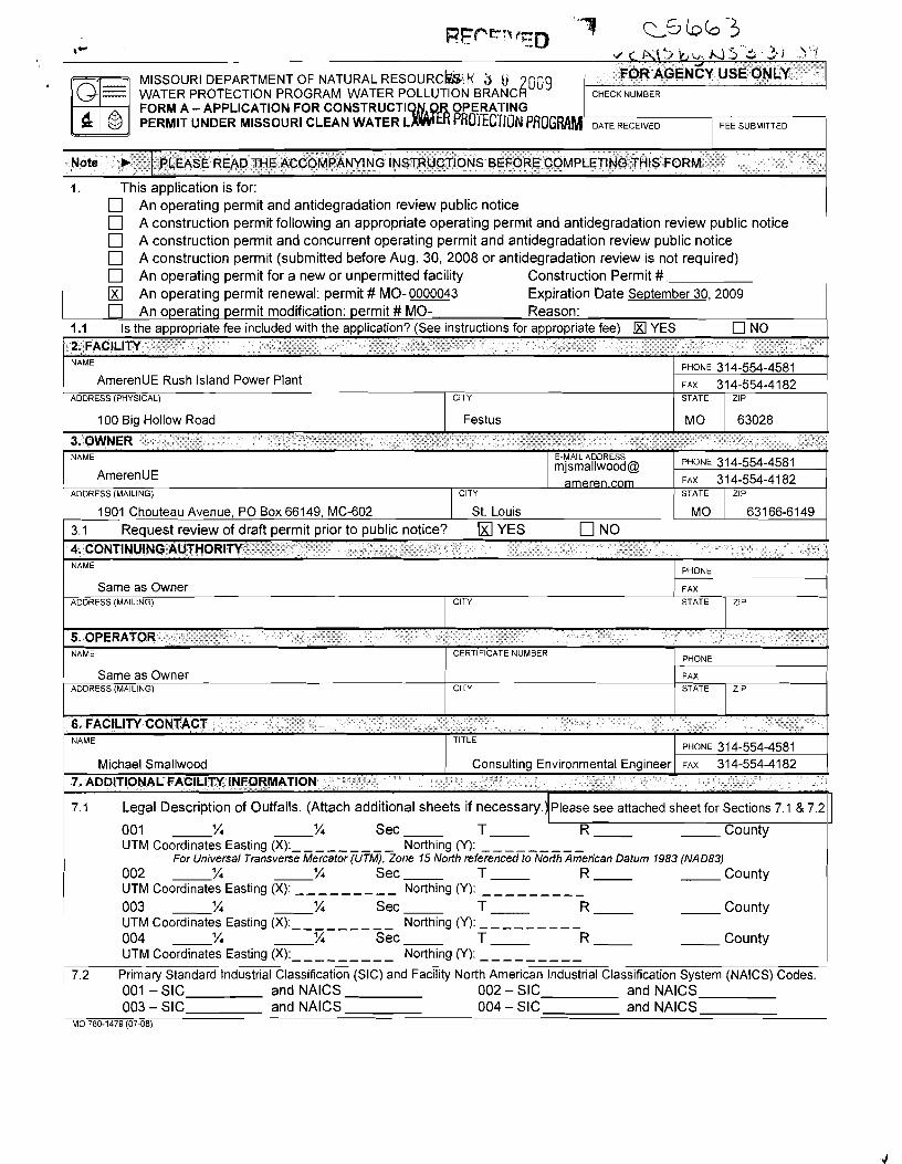
t-
MISSOURI DEPARTMENT OF NATURAL RESOURCW K j 099 I WATER PROTECTION PROGRAM. WATER PoLLu-[ION B R A N c i
FORM A - APPLICATION FOR CONSTRUCT1 PERMIT UNDER MISSOURI CLEAN WATER L
1. This application is for: An operating permit and antidegradation review public notice A construction permit following an appropriate operating permit and antidegradation review public notice A construction permit and concurrent operating permit and antidegradation review public notice A construction permit (submitted before Aug. 30, 2008 or antidegradation review is not required) An operating permit for a new or unpermitted facility Construction Permit # An operating permit renewal: permit # MO-0000043 Expiration Date September 30, 2009 An operating permit modification: permit # MO- Reason:
1 .I Is the appropriate fee included with the application? (See instructions for appropriate feel YES NO . . . . . . . . . - -
2. FACILITY t
1 100 Big Hollow Road I Festus I MO 1 63028 I I I I 1
3. OWNER L
NAME
AmerenUE Rush island Power Plant ADDRESS (PHYSICAL)
PHONE 31 4-554-4581 FAX 31 4-554-41 82
1901 Chouteau Avenue, PO Box 66149, MC-602 I st. ~ o u i s I MO 1 63166-6149 3.1 Reauest review of draft ~e rm i t ~ r i o r to ~ub l i c notice? kd YES n NO
CITY STATE
NAMEAmerenUE
- - 1 4. CONTINUING AUT HORlTY hAME
PrlOhE t
ZIP
E-MAIL ADDRESS m]smallwood@ C O ~
FAX 31 4-554-41 82 PHONE 314-554-4581
CITY
Same as Owner
I I 1
5. OPERATOR
I I I
6. FACILITY CONTACT t
STATE
ADDRESS (MAILING)
FAX
hAME
1 same as owner ADDRESS (MAILING)
NAME Michael Smallwood
ZIP
CITY STATE
CERT F CATE hJMBER
TITLE
Consulting Environmental Engineer
ZIP
PnONE f CITY
- - 7. ADDITIONAL FACILITY INFORMATION -
I
FAX STATE
7.1 Legal Description of Outfalls. (Attach additional sheets if necessary. Please see attached sheet for Sections 7.1 & 7.2
001 l4 '/4 Sec T- R- County UTM Coordinates Easting (XI:- - - - Northing (Y): ---------
For Universal Transverse Mercator (UTM), Zone 15 North referenced to North American Datum 1983 (NAD83) 002 '/4 '/4 Sec T- R- County UTM Coordinates Easting (X): - Northing (Y): - - - - - 003 '/4 '/4 Sec T- R- County UTM Coordinates Easting (XI:- - - - - Northing ('0: --------- 004 '/4 '/4 Sec T- R- County UTM Coordinates Easting (XI: Northing ('0: -
7.2 primary Standard Industrial Classification (SIC) and Facility North American Industrial Classification System (NAICS) Codes. 001 -SIC and NAlCS 002 - SIC and NAlCS 003 - SIC and NAlCS 004 - SIC and NAlCS
MO 780-1479 (0708)
ZIP
1
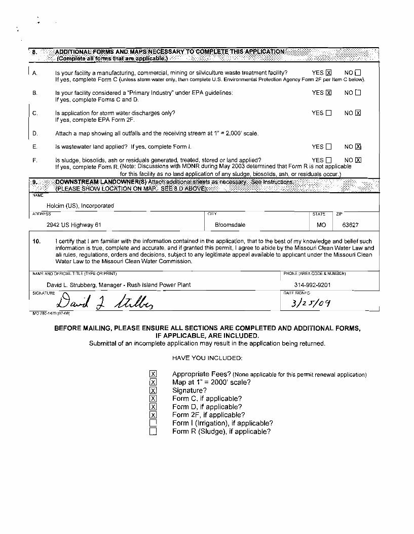
8. ADDITIONAL FORMS AND MAPS NECESSARY TO COMPLETE THIS APPLICATION (Complete all forms that are applicable.)
A. Is your facility a manufacturing, commercial, mining or silviculture waste treatment facility? YES N O 0 If yes, complete Form C (unless storm water only, then complete U.S. Environmental Protection Agency Form 2F per Item C below).
B. Is your facility considered a "Primary Industry" under EPA guidelines: If yes, complete Forms C and D.
C. Is application for storm water discharges only? If yes, complete EPA Form 2F.
YES rn N O D
D. Attach a map showing all outfalls and the receiving stream at 1" = 2,000' scale.
E. Is wastewater land applied? If yes, complete Form I. YES NO
F. Is sludge, biosolids, ash or residuals generated, treated, stored or land applied? YES q NO If yes, complete Form R. (Note: Discussions with MDNR during May 2003 determined that Form R is not applicable
for this faclllty as no land application of any sludge, biosol~ds, ash, or restduals occur.)
NAME
2942 US Highway 61 I Bloomsdale 1 MO 63627
Holcim (US), Incorporated
10. 1 certify that I am familiar with the information contained in the application, that to the best of my knowledge and belief such information is true, complete and accurate, and if granted this permit, I agree to abide by the Missouri Clean Water Law and all rules, regulations, orders and decisions, subject to any legitimate appeal available to applicant under the Missouri Clean Water Law to the Missouri Clean Water Commission.
ADDRESS
David L. Strubberg, Manager - Rush Island Power Plant 1 31 4-992-9201 DATE SIGNED
MO 780-1479 (0768)
BEFORE MAILING, PLEASE ENSURE ALL SECTIONS ARE COMPLETED AND ADDITIONAL FORMS, IF APPLICABLE, ARE INCLUDED.
Submittal of an incomplete application may result in the application being returned.
ZIP CITY
HAVE YOU INCLUDED:
STATE
rn Appropriate Fees? (None applicable for this permit renewal application)
rn Map at 1" = 2000' scale? rn Signature? rn Form C, if applicable? rn Form D, if applicable? rn Form 2F, if applicable?
Form I (Irrigation), if applicable? Form R (Sludge), if applicable?
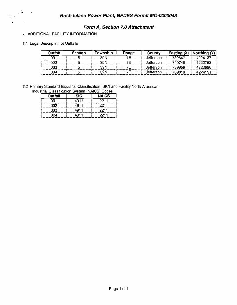
. . % . Rush lsland Power Plant, NPDES Permit MO-0000043
b
Form A, Section 7.0 Attachment 7. ADDITIONAL FACILITY IhlFORMATlON
7.1 Legal Description of Outfalls
I Outfall I Section I Township 1 Range I County I Easting (X) I Northing (Y) ! 001 ! 5 ! 39N ! 7E ! Jefferson ! 739847 ! 4224127 1 ~ - I----------------
- - ~
T---------------l----------------T----------------r----------------r----------------r--------------- i 1 002 1 5 I 39N 1 7E 1 Jefferson 1 740749 1 4222763 1 I----------------+----------------*----------------+----------------+----------------+----------------b---------------+
1 003 1 5 1 39N 1 7 E I Jefferson 1 739959 1 4223996 1 I----------------A---------------A----------------A----------------L----------------L----------------L---------------A
004 1 5 I 39N 7E I Jefferson 1 739819 1 4224151 1 !----------------J----------------A----------------4----------------L----------------L----------------L---------------d
7.2 Primary Standard Industrial Classification (SIC) and Facility North American Industrial Classification System (NAICS) Codes
I outfall I SIC 1 NAlCS 1
Page 1 of 1
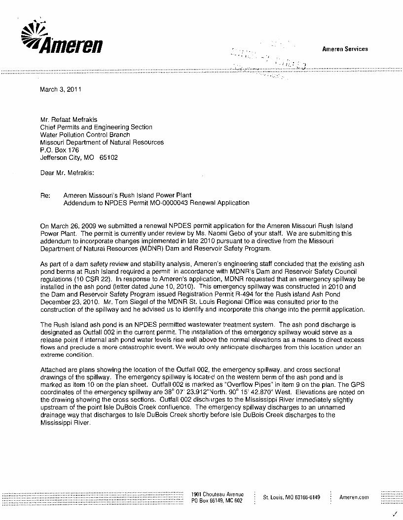
Ameren Services
March 3, 201 1
Mr. Refaat Mefrakis Chief Permits and Engineering Section Water Pollution Control Branch Missouri Department of Natural Resources P.O. Box 176 Jefferson City, MO 65102
Dear Mr. Mefrakis:
Re: Ameren Missouri's Rush lsland Power Plant Addendum to NPDES Permit MO-0000043 Renewal Application
On March 26, 2009 we submitted a renewal NPDES permit application for the Ameren Missouri Rush lsland Power Plant. The permit is currently under review by Ms. Naomi Gebo of your staff. We are submitting this addendum to incorporate changes implemented in late 201 0 pursuant to a directive from the Missouri Department of Natural Resources (MDIVR) Dam and Reservoir Safety Program.
As part of a dam safety review and stability analysis, Ameren's engineering staff concluded that the existing ash pond berms at Rush lsland required a permit in accordance with MDNR's Dam and Reservoir Safety Council regulations (10 CSR 22). In response to Ameren's application, MDNR requested that an emergency spillway be installed in the ash pond (letter dated June 10, 2010). This emergency spillway was constructed in 201 0 and the Dam and Reservoir Safety Program issued Registration Permit R-494 for the Rush lsland Ash Pond December 23, 2010. Mr. Tom Siegel of the MDNR St. Louis Regionai Office was consulted prior to the construction of the spillway and he advised us to identify and incorporate this change into the permit application.
The Rush lsland ash pond is an NPDES permitted wastewater treatment system. The ash pond discharge is designated as Outfall 002 in the current permit. The ~nstallation of thls emergency spillway would serve as a release point if internal ash pond water levels rise well above the normal elevations as a means to direct excess flows and preclude a more catastrophic event. We woula only anticipate discharges from this location under an extreme condition.
Attached are plans showing the location of the Outfall 002, the emergency sp~llway, and cross sectional drawlngs of the spillway The emergency splllway is located on the western berm of the ash pond and is marked as item 10 on the plan sheet. Outfall 002 IS rnarked as "Overflow P~pes" 1t-1 item 9 on the plan. The GPS coordinates of the emergency spillway are 38' 07' 23.912"Uorth. 90' 15' 42.870" West. Elevations are noted on the drawing showlng the cross sections. Outfall 002 disch'irges to the Mississippi River immediately slightly upstream of the point lsle DuBois Creek confluence. The emergency spillway discharges to an unnamed drainage way that discharges to lsle DuBois Creek shortly before lsle DuBois Creek discharges to the Mississippi River.
.............. ............................................................................................................... .............. ............................................................................................................... ............................................................................................................... l g o l Chouteau i St. Louis, MO 63166-6149 i Ameren.com :::::::::::::: ............................................................................................................... .............. ............................................................................................................... PO Box 66149, MC 602 : .............. ...............................................................................................................
, Please do not hesitate to contact me or Nancy Morgan of my staff (at 314-554-3065) if you have questions.
Managing Supervisor, Water Quality Environmental Services T 31 4.554.2280 F 31 4.554.41 82 [email protected]
cc: Ms. IVaomi Gebo, MDNR, WPCP Tom Siegel, MDhlR St. Louis Regional Office
Ameren Services
Environmental Services 314.554.4581 (Phone) 314.554.4182 (Facsimile) [email protected]~
March 26,2009
One Ameren Plaza 1901 Chouteau Avenue PO Box 66149 St. Louis, MO 63166-6149
Mr. Tim Stallman, R.G. WATER PROECICIION PRUGW Environmental Specialist NPDES Permit and Engineering Section Water Pollution Control Branch
AI V. Missouri Department of Natural Resources S' '7) P.O. Box 176 WAmemn Jefferson City, MO 65102
Dear Mr. Stallman:
Re: AmerenUE Rush Island Power Plant NPDES Permit MO-0000043 Renewal Application
In accordance with State and Federal regulations, enclosed is a renewal application with original signatures and a copy of the same for the AmerenUE Rush Island Power Plant, NPDES Permit MO-0000043. We believe that this timely application is complete, with all required forms, signatures, and drawings.
The application also includes a set of Attachments that provide additional details regarding information required in the application forms.
Please contact me at 314-554-4581 if there are any questions regarding this permit renewal application.
Sincerely,
Michael J. Smallwood Consulting Environmental Engineer
Enclosures
a subsidiarv of Ameren Corooration
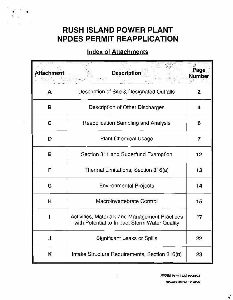
RUSH ISLAND POWER PLANT NPDES PERMIT REAPPLICATION
Index of Attachments
Plant Chemical Usage
Section 31 1 and Superfund Exerr~ption
Environmental Projects
Significant Leaks or Spills
Intake Structure Requirements, Section 31 6(b)
NPDES Permit MO-0000043
Revised March 19,2009
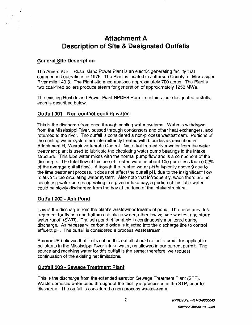
Attachment A Description of Site & Designated Outfalls
General Site Description
The AmerenUE - Rush Island Power Plant is an electric generating facility that commenced operations in 1976. The Plant is located in Jefferson County, at Mississippi River mile 140.3. The Plant site encompasses approximately 700 acres. The Plant's two coal-fired boilers produce steam for generation of approximately 1250 MWe.
The existing Rush Island Power Plant NPDES Permit contains four designated outfalls; each is described below.
Outfall 001 - Non contact coolinq water
This is the discharge from once-through cooling water systems. Water is withdrawn from the Mississippi River, passed through condensers and other heat exchangers, and returned to the river. The outfall is considered a non-process wastestream. Portions of the cooling water system are intermittently treated with biocides as described in Attachment H, Macroinvertebrate Control. Note that treated river water from the water treatment plant is used to lubricate the circulating water pump bearings in the intake structure. This lube water mixes with the normal pump flow and is a component of the discharge. The total flow of this use of treated water is about 100 gpm (less than 0.02% of the average outfall flow). Although the treated water pH is typically above 9 due to the lime treatment process, it does not affect the outfall pH, due to the insignificant flow relative to the circulating water system. Also note that infrequently, when there are no circulating water pumps operating in a given intake bay, a portion of this lube water could be slowly discharged from the bay at the face of the intake str~~cture.
Outfall 002 - Ash Pond
This is the discharge from the plant's wastewater treatment pond. The pond provides treatment for fly ash and bottom ash sluice water, other low volume wastes, and storm water runoff (SWR). The ash pond effluent pH is continuously monitored during discharge. As necessary, carbon dioxide is injected into the discharge line to control effluent pH. The outfall is considered a process wastestream.
AmerenUE believes that limits set on this outfall should reflect a credit for applicable pollutants in the Mississippi River intake water, as allowed in our current permit. The source and receiving water for ,this outfall is the same; therefore, we request continuation of the existing net limitations.
Outfall 003 - Sewaqe Treatment Plant
This is the discharge from the extended aeration Sewage Treatment Plant (STP). Waste domestic water used throughout the facility is processed in the STP, prior to discharge. The outfall is considered a non-process wastestream.
NPDES Permit MO-0000043
Revised March 79,2009
Note that the Missouri Department of Natural Resources issued a construction permit (22-7685) on November 3, 2008 to support a project that will replace the existing STP. The new STP will have a Population Equivalent of 235 and will be equipped with ultraviolet disinfection and flow equalization. We respectfully request that the reissued facility NPDES permit include interim limitations for the current S-TP and final limitations to support the new STP.
Outfall 004 - Storm Water Runoff
This discharge is the plant's sole remaining storm water runoff (SWR) outfall. Physically, the outfall consists of a 36 inch corrugated metal pipe, which empties onto the bank of the Mississippi River. The drainage area of this outfall consists of the following:
P Yard areas east of the storeroom and north of the plant, including the switchyard, P Roof drains from the administration building and the "Unit 2" side of the turbine
building,
I P Storeroom laydown area and loading dock ramp, P Area around the northwest corner of the power block near the electrical/maintenance
shop addi.tion, P Northeast and northwest corners of the employee parking lot north of the switchyard, P Portions of the plant access road.
No process wastewater sources are included in this storm water outfall. Other seasonal or infrequent discharges via Outfall 004 are the result of surface washes using treated water without detergents and include:
P Air conditioning coils, P Exterior building surfaces, P Yard areas contributory to Outfall 004
Surface washdowns to the outfall will not take place in areas where spills or leaks of toxic or hazardous materials have occurred and have not been thoroughly removed.
Although no structural controls are in place to reduce pollutants in the storm water runoff routed to this outfall, the Rush Island plant is committed to utilizing Best Management Practices (BNIPs) to assure orlgoing protection of effluent quality. BMPs include documented inspection of the drainage areas contributory to Outfall 004 to assure no significant materials or activities exist that could result in potential contamination of the discharged storm water. Please note that "Attachment I - Activities, Materials and Management Practices with Potential to Impact Storm Water Quality" provides additional details regarding BMPs utilized at Rush Island.
NPDES Permit M0-0000043
Revised March 19,2009
Attachment B Description of Other Discharges
Return of River Water
The Rush Island Plant has six points at which river water with no added pollutants are returned to the river that are not designated as outfalls. All are associated with the plant intake structure:
P Intake screen wash - Mississippi River water is used to wash traveling screens at the intake and discharged at the downstream face of the structure;
P Intake screen wash strainer backwash - Filter backwash from two river water basket strainers (used to prevent screen wash system nozzles from plugging) is discharged from the back (western) side of the intake structure;
P Caisson (Intake) sumps - There are two sumps in the intake structure; their discharges consist primarily of pump seal water, which is released from the back (western) side of the intake structure; and
P Warming line -This line is an alternative routing for a portion of the flow through Outfall 001 (non-contact cooling water). During winter months (as ambient terr~perature may dictate), a portion of this outfall is diverted through the warming line and discharged at the face of the intake structure to prevent ice formation on the intake screens and trash racks. This system may also be used infrequently, throughout the year for other operational needs. We have reviewed the effects of operating this line in other seasons and do not believe there are any significant impacts. Additional details are provided in "Attachment F - Thermal Limitations, Section 31 6(a)".
Well Testinq
The plant's water supply well is tested infrequently. During the test, the well discharges at a rate of approximately 30 gpm for no more than 30 minutes. The discharge flow is directed to adjacent gravel covered areas.
Well Rehabilitation
The plant's potable water well (currently under construction) and water supply well may infrequently require periodic rehabilitation to primarily remove carbonate deposits. A typical well rehabilitation would include:
P Hydrochloric Acid recirculation with neutralized wastewater directed to the ash pond.
9 A milder Hydrochloric Acid solution recirculation with neutralized wastewater directed to the ash pond.
P Sodium Hypochlorite recirculation with neutralized wastewater directed to the ash pond.
NPDES Permit MO-0000043
Revised March 19.2009
> Well testing to determine pump characteristics and to determine the specific capacity of the well. Water discharged during this step would be directed to the ash pond.
Other Storm water Discharges
Additional potential storm water point sources, identified in previous permit applications, include the following:
> On the west side of the plant site near the convergence of the railroad loop tracks, two 36-inch corrugated metal culverts convey storm water runoff into a creek, contributory to the Mississippi River. Flow occurs from these two culverts only during periods of extremely heavy precipitation, when areas may become ponded with standing water. While the majority of the storm water from this area is conveyed to the plant ash pond via a separate series of culverts, a small portion will discharge into the creek. The areas that are influenced by this drainage area include: general plant storage and equipment laydown areas used during plant maintenance outages, a small portion of the plant access road, and a vegetated field west of the plant area.
Due to the topography of the drainage area and swale/culvert elevations, none have discharge flows during normal rainfall events. As a result, the DNR elected not to specify these as outfalls in our existing permit. We concur with this determination and request that these discharges not be listed as outfalls in the reissued permit.
NPDES Permit MO-0000043
Revised March 19,2009
Attachment C Reapplication Sampling and Analysis
Analvsis and Flow Data
This section describes the source of data listed in Forms C, D and 2F
9 Data from the special sampling project described below is listed in the "Maximum Daily Value1' columns. Where applicable, the flows monitored during the sampling period are shown here and used to calculate mass discharges under this heading.
9 Values listed under the headings "Maximum 30 Day Value" and "Long Term Average Value" were compiled from data required by the existing NPDES permit during the November 2007 - October 2008 period. Mass discharges under these headings were calculated using the appropriate long-term average flow rates.
9 "Intake" columns list data collected from a modified (four aliquot) composite or four individual grabs, as appropriate, of the Mississippi River.
Samplinq and Analvsis for this Reapplication
A series of water samples were collected by AmerenLlE staff at Outfall 004 on December 9, 2008 and from Outfalls 001, 002, 003, and the Mississippi River on January 13, 2009.
Samples were collected from Storm Water Outfall 004 using automatic sampling equipment initiated by flow in the outfall. The sampled precipitation event only resulted in runoff to obtain a "first flush" sample. Data from the first flush sample is also reported in the "composite" column on Form 2F.
Analyses of Outfall 001 and Mississippi River samples consisted of four individual grabs (for non-compositing parameters: fecal coliform, pH, oil & grease, and temperature) and modified (four aliquot) composites.
Samples analyzed for Outfalls 002 and 003 included both individual grabs (for non- compositing parameters) and 24-hour flow proportional composites (consisting of 8 aliquots).
Following on-site analysis of pH and sulfite (Outfall 002 and Mississippi River only), samples were preserved and subsequently analyzed in accordance with 40 CFR Part 136 and 10 CSR 20-7.015(9). The AmerenUE Laboratory Services Department and two contract laboratories (PDC Laboratories Incorporated and Teledyne Brown Engineering Incorporated) performed the analyses.
The plant output during the process outfall sampling event on January 13, 2009 was 29,178 MWHrs total, or approximately 97.35% of the rated full generating capacity.
NPDES Permit MO-0000043
Revised March 19,2009
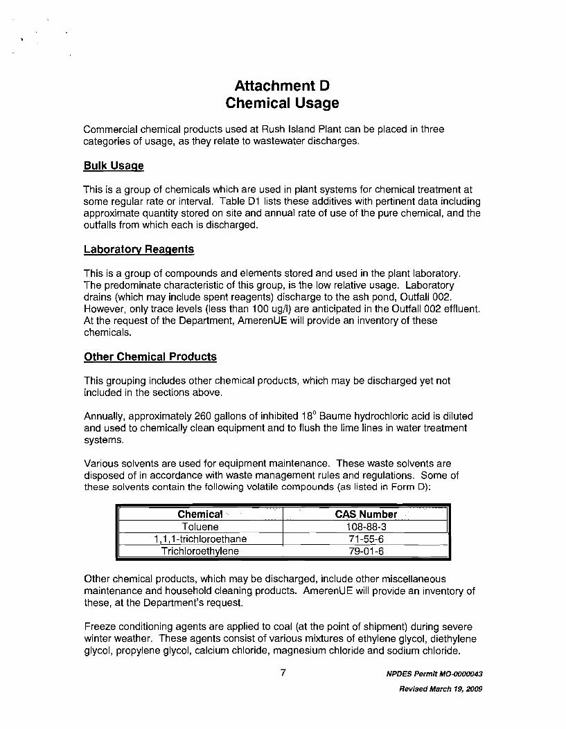
Attachment D Chemical Usage
Commercial chemical products used at Rush Island Plant can be placed in three categories of usage, as they relate to wastewater discharges.
Bulk Usage
This is a group of chemicals which are used in plant systems for cherr~ical .treatment at some regular rate or interval. Table D l lists these additives with pertinent data including approximate q~~anti ty stored on site and annual rate of use of the pure chemical, and the outfalls from which each is discharged.
Laboratorv Reaqents
This is a group of compounds and elements stored and used in the plant laboratory. The predominate characteristic of this group, is the low relative usage. Laboratory drains (which may include spent reagents) discharge to the ash pond, Outfall 002. However, only trace levels (less than 100 ugll) are anticipated in the Outfall 002 effluent. At the request of the Department, AmerenUE will provide an inventory of these chemicals.
Other Chemical Products
This grouping includes other chemical products, which may be discharged yet not included in the sections above.
Annually, approximately 260 gallons of inhibited 18' Baume hydrochloric acid is diluted and used to chemically clean equipment and to flush the lime lines in water treatment systems.
Various solvents are used for equipment maintenance. These waste solvents are disposed of in accordance with waste management rules and regulations. Some of these solvents contain the following volatile compounds (as listed in Form D):
Other chemical products, which may be discharged, include other miscellaneous maintenance and household cleaning products. AmerenUE will provide an inventory of these, at the Department's request.
Chemical Toluene
1,1 , I -trichloroethane Trichloroethylene
Freeze conditioning agents are applied to coal (at the point of shipment) during severe winter weather. These agents consist of various mixtures of ethylene glycol, diethylene glycol, propylene glycol, calcium chloride, magnesium chloride and sodium chloride.
CAS Number 108-88-3 71 -55-6 79-01 -6
NPDES Permit MO-0000043
Revised March 19,2009
When used, freeze-conditioning agents are applied at a rate of approximately 2 pints per ton of coal. Freeze conditioning agents may also be used at the coal receiving area in the coal handling system at the Rush Island plant.
Dust suppression agents are also applied to coal. We currently use four Benetech products: BT-205W, BT-415, BT-515 and BT-100F2. These would be used in coal handling systems. As shown in Attachment I, coal pile runoff is either retained on site without surface discharge, or routed to the ash pond (Outfall 002) for treatment. As a result, a small amount of these agentslproducts may be discharged from the ash pond, Outfall 002.
Each of the two boilers at Rush Island is chemically cleaned, approximately every six years. Boiler chemical cleaning wastes are not discharged but are thermally treated at the plant by injecting them into an operating boiler. Thermally treating these non- hazardous cleaning wastes is preferred over co-treatment in the ash pond. Evaporation of the spent cleaning solutions vaporizes the aqueous fraction and destroys the organic cleaning agent. Testing has been conducted by the Electric Power Research Institute on discharges from utility boilers during thermal treatment of these wastestreams. It was shown that emissions of most metal corr~pounds from .the cleaning wastes were insignificant compared to the normal plant emissions. In fact, emissions associated with boiler cleaning waste evaporation were small compared to the normal fluctuations in coal composition and ash content.
NPDES Permit MO-0000043
Revised March 19,2009
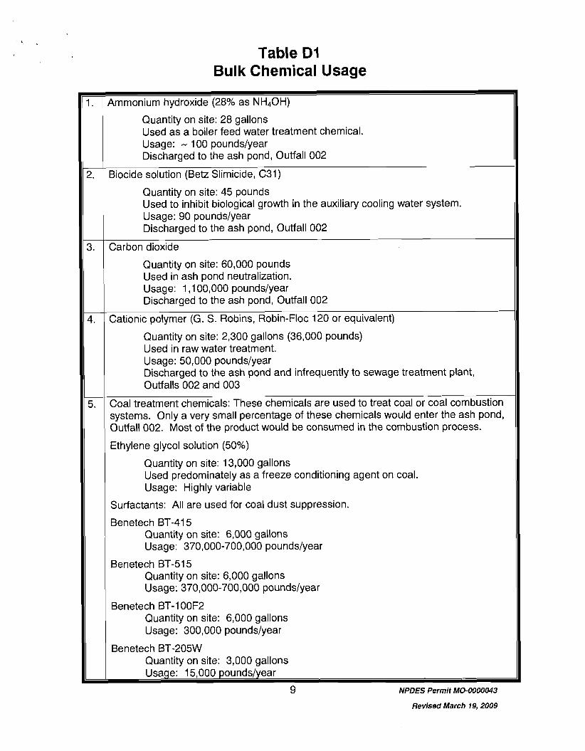
Table D l Bulk Chemical Usage
4mmonium hydroxide (28% as hlH40H)
Quantity on site: 28 gallons Used as a boiler feed water treatment chemical. Usage: - 100 poundslyear Discharged to the ash pond, Outfall 002
3iocide solution (Betz Slimicide, C31)
Quantity on site: 45 pounds Used to inhibit biological growth in the auxiliary coolirlg water system. Usage: 90 poundslyear Discharged to the ash pond, Outfall 002
Sarbon dioxide
Quantity on site: 60,000 pounds Used in ash pond neutralization. Usage: 1,100,000 poundslyear Discharged to the ash pond, Outfall 002
Sationic polymer (G. S. Robins, Robin-Floc 120 or equivalent)
Quantity on site: 2,300 gallons (36,000 pounds) Used in raw water treatment. Usage: 50,000 poundslyear Discharged to the ash pond and infrequently to sewage treatment plant, Outfalls 002 and 003
Coal treatment chemicals: These chemicals are used to treat coal or coal combustion systems. Only a very small percentage of these chemicals would enter the ash pond, Outfall 002. Most of the product would be consumed in the combustion process.
Ethylene glycol solution (50%)
Quantity on site: 13,000 gallons Used predominately as a freeze conditioning agent on coal. Usage: Highly variable
Surfactants: All are used for coal dust suppression.
Benetech BT-415 Quantity on site: 6,000 gallons Usage: 370,000-700,000 poundslyear
Benetech BT-515 Quantity on site: 6,000 gallons Usage: 370,000-700,000 poundslyear
Benetech BT-100F2 Quantity on site: 6,000 gallons Usage: 300,000 poundslyear
Benetech BT-205W Quantity on site: 3,000 gallons usage: 15,000 poundslyear
9 NPDES Permit MO-0000043
Revised March 19,2009
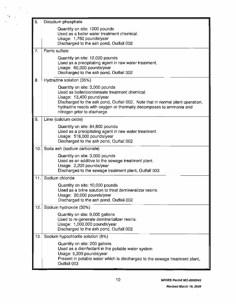
NPDES Permit MO-0000043
Revised March 19,2009
. 6.
7.
8.
9.
10.
Disodium phosphate
Quantity on site: 1000 pounds Used as a boiler water treatment chemical. Usage: 1,750 poundslyear Discharged to the ash pond, Outfall 002
Ferric sulfate
Quantity on site: 12,000 pounds Used as a precipitating agent in raw water treatment. Usage: 60,000 poundslyear Discharged to the ash pond, Outfall 002
Hydrazine solution (35%)
Quantity on site: 3,000 pounds Used as boilerlcondensate treatment chemical. Usage: 13,400 poundlyear Discharged to the ash pond, Outfall 002. Note that in normal plant operation, hydrazine reacts with oxygen or thermally decomposes to ammonia and nitrogen prior to discharge
Lime (calcium oxide)
Quantity on site: 84,600 pounds Used as a precipitating agent in raw water treatment. Usage: 51 8,000 poundslyear Discharged to the ash pond, Outfall 002
Soda ash (sodium carbonate)
11.
12.
13.
Quantity on site: 3,000 pounds Used as an additive to the sewage treatment plant. Usage: 2,200 poundslyear Discharged to the sewage treatment plant, Outfall 003
Sodium chloride
Quantity on site: 10,000 pounds Used as a brine solution to treat demineralizer resins. Usage: 20,000 poundslyear Discharged to the ash pond, Outfall 002
Sodium hydroxide (50%)
Quantity on site: 9,000 gallons Used to re-generate deminerializer resins. Usage: 1,000,000 poundslyear Discharged to the ash pond, Outfall 002
Sodium hypochlorite solution (6%)
Quantity on site: 200 gallons Used as a disinfectant in the potable water system Usage: 5,200 poundslyear Present in potable water which is discharged to the sewage treatment plant, Outfall 003
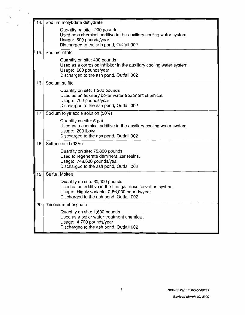
NPDES Permit MO-0000043
Revised March 19,2009
14.
15.
16.
17.
18.
19.
20.
Sodium molybdate dehydrate
Quantity on site: 200 pounds Used as a chemical additive in the auxiliary cooling water system Usage: 500 poundslyear Discharged to the ash pond, Outfall 002
Sodium nitrite
Quantity on site: 400 pounds Used as a corrosion inhibitor in the auxiliary cooling water system. Usage: 600 poundslyear Discharged to the ash pond, Outfall 002
Sodium sulfite
Quantity on site: 1,200 pounds Used as an auxiliary boiler water treatment chemical. Usage: 700 poundslyear Discharged to the ash pond, Outfall 002
Sodium tolytriazole solution (50%)
Quantity on site: 5 gal Used as a chemical additive in the auxiliary cooling water system. Usage: 200 Ibslyr Discharged to the ash pond, Outfall 002
Sulfuric acid (93%)
Quantity on site: 75,000 pounds Used to regenerate demineralizer resins. Usage: 748,000 poundslyear Discharged to the ash pond, Outfall 002
Sulfur, Molten
Quantity on site: 60,000 pounds Used as an additive in the flue gas desulfurization system. Usage: Highly variable, 0-56,000 poundslyear Discharged to the ash pond, Outfall 002
Trisodium phosphate
Quantity on site: 1,600 pounds Used as a boiler water treatment chemical. Usage: 4,700 poundslyear Discharged to the ash pond, Outfall 002
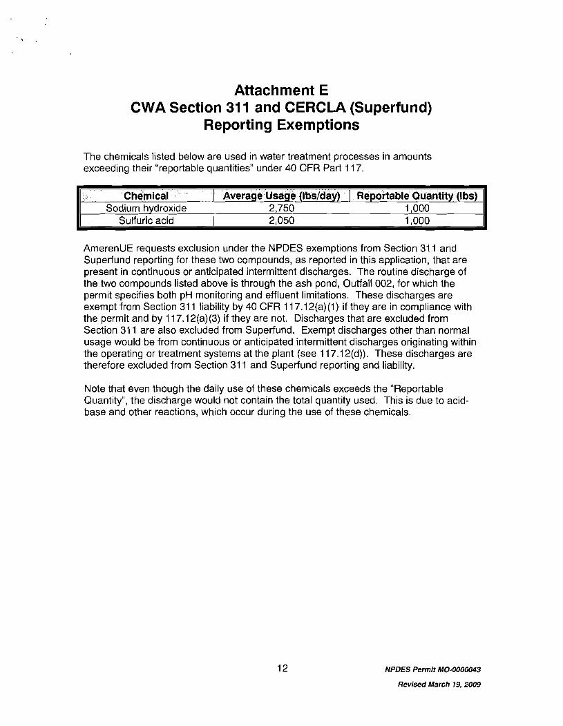
Attachment E CWA Section 31 1 and CERCLA (Superfund)
Reporting Exemptions
The chemicals listed below are used in water treatment processes in amounts exceeding their "reportable quantities" under 40 CFR Part 11 7.
AmerenUE requests exclusion under the NPDES exemptions from Section 31 1 and Superfund reporting for these two compounds, as reported in this application, that are present in continuous or anticipated intermittent discharges. The routine discharge of the two compounds listed above is through the ash pond, Outfall 002, for which the permit specifies both pH monitoring and effluent limitations. These discharges are exempt from Section 31 1 liability by 40 CFR 11 7.1 2(a)(l) if they are in compliance with the permit and by 11 7.1 2(a)(3) if they are not. Discharges that are excluded from Section 31 1 are also excluded from Superfund. Exempt discharges other than normal usage would be from continuous or anticipated intermittent discharges originating within the operating or treatment systems at the plant (see 11 7.1 2(d)). These discharges are therefore excluded from Section 31 1 and Superfund reporting and liability.
Chemical - Sodium hydroxide
Sulfuric acid
Note that even though the daily use of these chemicals exceeds the "Reportable Quantity", the discharge would not contain the total quantity used. This is due to acid- base and other reactions, which occur during the use of these chemicals.
NPDES Permit MO-0000043
Revised March 19,2009
Average Usage (Ibslday) 2,750 2,050
Reportable Quantity (Ibs) 1,000 1,000
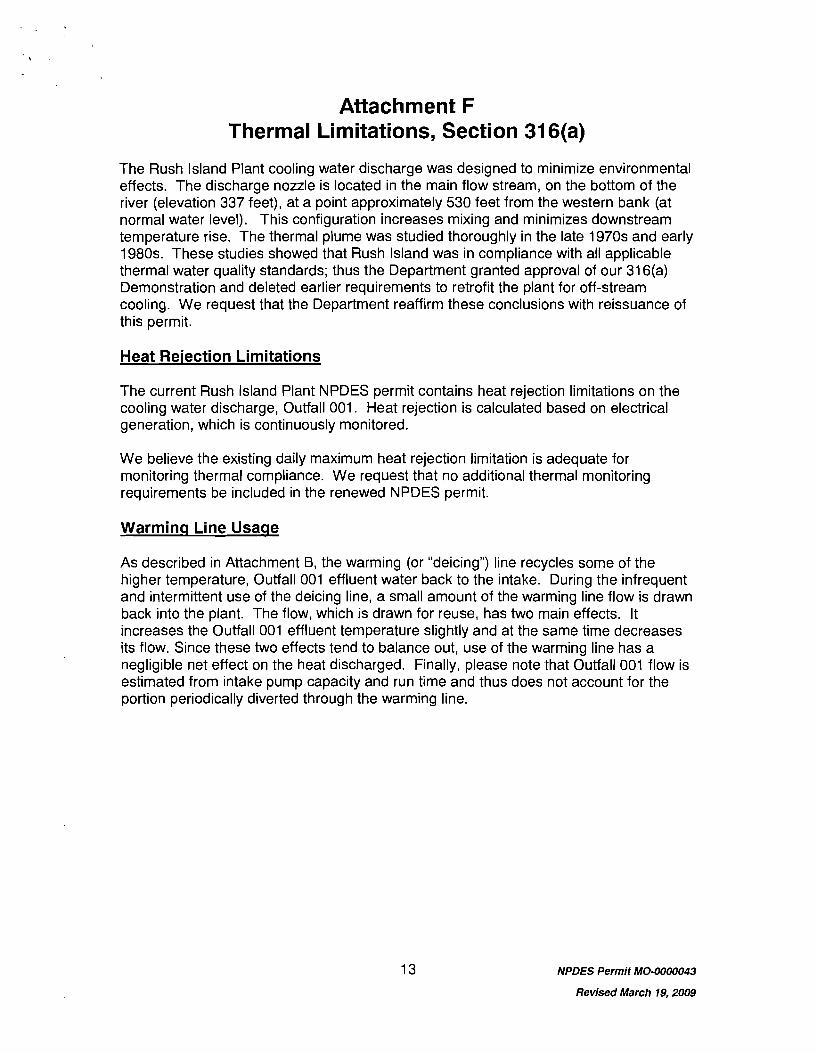
Attachment F Thermal Limitations, Section 31 6(a)
The Rush Island Plant cooling water discharge was designed to minimize environmental effects. The discharge nozzle is located in the main flow stream, on the bottom of the river (elevation 337 feet), at a point approximately 530 feet from the western bank (at normal water level). This configuration increases mixing and minimizes downstream temperature rise. The thermal plume was studied thoroughly in the late 1970s and early 1980s. These studies showed that Rush Island was in compliance with all applicable thermal water quality standards; thus the Department granted approval of our 316(a) Demonstration and deleted earlier requirements to retrofit the plant for off-stream cooling. We request that the Department reaffirm these conclusions with reissuance of this permit.
Heat Rejection Limitations
The current Rush Island Plant NPDES permit contains heat rejection limitations on the cooling water discharge, Outfall 001. Heat rejection is calculated based on electrical generation, which is continuously monitored.
We believe the existing daily maximum heat rejection limitation is adequate for monitoring thermal compliance. We request that no additional thermal monitoring requirements be included in the renewed NPDES permit.
Warminq Line Usaqe
As described in Attachment B, the warming (or "deicing") line recycles some of the higher temperature, Outfall 001 effluent water back to the intake. During the infrequent and intermittent use of the deicing line, a small amount of the warming line flow is drawn back into the plant. The flow, which is drawn for reuse, has two main effects. It increases the Outfall 001 effluent temperature slightly and at the same time decreases its flow. Since these two effects tend to balance out, use of the warming line has a negligible net effect on the heat discharged. Finally, please note .that Outfall 001 flow is estimated from intake pump capacity and run time and thus does not account for the portion periodically diverted through the warming line.
NPDES Permit MO-0000043
Revised March 19,2009
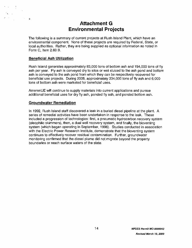
Attachment G Environmental Projects
The following is a summary of current projects at Rush Island Plant, which have an environmental component. None of these projects are required by Federal, State, or local authorities. Rather, they are being supplied as optional information as noted in Form C, Item 2.60 B.
Beneficial Ash Utilization
Rush Island generates approximately 83,000 tons of bottom ash and 194,000 tons of fly ash per year. Fly ash is conveyed dry to silos or wet sluiced to the ash pond and bottom ash is conveyed to the ash pond from which they can be respectively recovered for beneficial use projects. During 2008, approximately 334,000 tons of fly ash and 6,000 tons of bottom ash were marketed for beneficial uses.
AmerenUE will continue to supply materials into current applications and pursue additional beneficial uses for dry fly ash, ponded .fly ash, and ponded bottom ash.
Groundwater Remediation
In 1992, Rush Island staff discovered a leak in a buried diesel pipeline at the plant. A series of remedial activities have been undertaken in response to the leak. These included a progression of technologies: first, a pneumatic hydrocarbon recovery system (oleophilic skimmers), then, a dual well recovery system, and finally, the bioventing system (which began operating in September, 1996). Studies conducted in association with the Electric Power Research Institute, demonstrate that the bioventing system continues to effectively recover residual contamination. Further, groundwater monitoring confirmed that the diesel plume did not migrate beyond the property boundaries or reach surface waters of the state.
NPDES Permit MO-0000043
Revised March 19,2009
Attachment H Macroinvertebrate Control
Rush Island Plant has a monitoring program to detect the settlement and growth of zebra mussels within systems vulnerable to macroinvertebrate fouling. Currently, biocide treatments are scheduled semi-annually to control populations before fouling occurs.
While various approaches have been considered and evaluated, our current strategy consists of molluscicide treatment of intake structure cells, auxiliary coolers (condensate, condenser, and jacket water coolers), and high and low pressure untreated (raw) water systems, using the following commercial chemical product or equivalent:
9 GE-Betz Spectrus CT 1300, dosed at 5-1 0 ppm; or 9 Calgon H-130, dosed at approximately 5 ppm; or 9 Buckman Laboratories Bulab 6086, dosed at 5-1 0 ppm.
The intake structure is divided into four cells, each with its own traveling screens and pump, with two cells serving each of the plant's two generating units. The treatment process consists of isolating two of the intake cells (one per unit) by lowering gates, which are behind the bar racks located on the face of the caisson, and shutting off the pumps. The molluscicide is then added to the water in the cell to achieve the target dosage (see above). This target concentration is maintained for a period of approximately eight hours, adding product as necessary, while the cell remains isolated. When treatment is complete, the gates are raised and the pumps restored to service. The residual biocide from these treatments reacts with flows from the other pumps prior to discharge via Outfall 001, precluding the need to add detoxifying agents. Note that there is some potential for a portion of the treated water to escape from the face of the intake cell through leakage past the gates, either during treatment or while the pumps are being restored. However, we believe that there are no significant risks or impacts due to the low magnitude of these losses and the high relative flow of the river.
Untreated river water distribution systems (low and high pressure raw water and service water) also require treatment to avoid pipe pluggage. These systems are treated twice per year, by pumping the molluscicide into the suction of the low and high pressure raw water pumps and maintaining the target dosage (see above) for approximately eight hours. The majority of the water from these systems eventually flows to the plant ash pond (Outfall 002). The residual biocide from these treatments reacts with mud, silt or sediment within the ash pond, prior to discharge via Outfall 002, precluding the need to add detoxifying agents. Note that a small portion of water from these systems is returned to the circulating water system (Outfall 001). As stated above, mixing with other flows within the circulating water system precludes the need for detoxification of this wastestream.
WET testing during these operations has demonstrated that the discharges are non- toxic. Product selection for a particular treatment is based on competitive bids, which consider cost, effectiveness, and other factors. We are not considering other control strategies or treatment points at this time. If new needs or op'tions develop, we will
NPDES Permit MO-0000043
Revised March 19,2009
provide appropriate notice, consistent with permit standard conditions and applicable regulations.
NPDES Permit MO-0000043
Revised March 19,2009
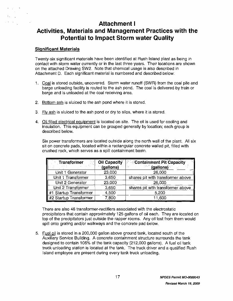
Attachment I Activities, Materials and Management Practices with the
Potential to Impact Storm water Quality
Significant Materials
Twenty-six significant materials have been identified at Rush Island plant as being in contact with storm water currently or in the last three years. Their locations are shown on the attached Drawing SW2. Note that chemical usage is also described in Attachment D. Each significant material is numbered and described below:
1. Coal is stored outside, uncovered. Storm water runoff (SWR) from the coal pile and barge unloading facility is routed to the ash pond. The coal is delivered by train or barge and is unloaded at the coal receiving area.
2. Bottom ash is sluiced to the ash pond where it is stored.
3. Flv ash is sluiced to the ash pond or dry to silos, where it is stored.
4. Oil filled electrical equipment is located on site. The oil is used for cooling and insulation. This equipment can be grouped generally by location; each group is described below.
Six power transformers are located outside along the north wall of the plant. All six sit on concrete pads, located within a rectangular concrete walled pit, filled with crushed rock, which serves as a spill containment basin.
There are also 48 transformer-rectifiers associated with the electrostatic precipitators that contain approximately 125 gallons of oil each. They are located on top of the precipitators just outside the rapper rooms. Any oil lost from them would spill onto grating and/or walkways and the concrete pad below.
Transformer
Unit 1 Generator Unit 1 Transformer Unit 2 Generator
Unit 2 Transformer # I Startup Transformer #2 Startup Transformer
5. Fuel oil is stored in a 200,000 gallon above ground tank, located south of the Auxiliary Service Building. A concrete containment structure surrounds the tank designed to contain 106% of the tank capacity (21 2,000 gallons). A fuel oil tank truck unloading station is located at the tank. The truck driver and a qualified Rush Island employee are present during every tank truck unloading.
NPDES Permit MO-0000043
Revised March 19,2009
Oil Capacity (gallons) 23,000 3,650 23,000 3,650 4,500 7,800
Containment Pit Capacity (gallons) 26,000
shares pit with transformer above 26,000
shares pit with transformer above 5,200 11,600
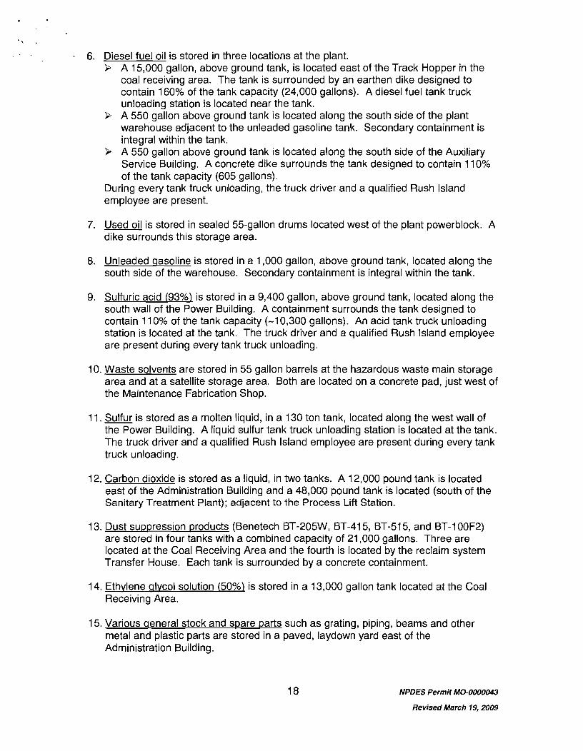
. . 6. Diesel fuel oil is stored in three locations at the plant.
9 A 15,000 gallon, above ground tank, is located east of the Track Hopper in the coal receiving area. The tank is surrounded by an earthen dike designed to contain 160% of the tank capacity (24,000 gallons). A diesel fuel tank truck unloading station is located near the tank.
9 A 550 gallon above ground tank is located along the south side of the plant warehouse adjacent to the unleaded gasoline tank. Secondary containment is integral within the tank.
9 A 550 gallon above ground tank is located along the south side of the Auxiliary Service Building. A concrete dike surrounds the tank designed to contain 11 0% of the tank capacity (605 gallons).
During every tank truck unloading, the truck driver and a qualified Rush Island employee are present.
7. Used oil is stored in sealed 55-gallon drums located west of the plant powerblock. A dike surrounds this storage area.
8. Unleaded gasoline is stored in a 1,000 gallon, above ground tank, located aloug the south side of the warehouse. Secondary containment is integral within the tank.
9. Sulfuric acid (93%) is stored in a 9,400 gallon, above ground tank, located along the south wall of the Power Building. A containment surrounds the tank designed to contain 11 0% of the tank capacity (-1 0,300 gallons). An acid tank truck unloading station is located at the tank. The truck driver and a qualified Rush Island employee are present during every tank truck unloading.
10. Waste solvents are stored in 55 gallon barrels at the hazardous waste main storage area and at a satellite storage area. Both are located on a concrete pad, just west of the Maintenance Fabrication Shop.
11. Sulfur is stored as a molten liquid, in a 130 ton tank, located along the west wall of the Power Building. A liquid sulfur tank truck unloading station is located at the tank. The truck driver and a qualified Rush Island employee are present during every tank truck unloading.
12. Carbon dioxide is stored as a liquid, in two tanks. A 12,000 pound tank is located east of the Administration Building and a 48,000 pound tank is located (south of the Sanitary Treatment Plant); adjacent to the Process Lift Station.
13. Dust suppression products (Benetech BT-205W, BT-415, BT-515, and BT-100F2) are stored in four tanks with a combined capacity of 21,000 gallons. Three are located at the Coal Receiving Area and the fourth is located by the reclaim system Transfer House. Each tank is surrounded by a concrete containment.
14. Ethvlene alvcol solution (50%) is stored in a 13,000 gallon tank located at the Coal Receiving Area.
15. Various aeneral stock and spare parts such as grating, piping, beams and other metal and plastic parts are stored in a paved, laydown yard east of the Administration Building.
NPDES Permit MO-0000043
Revised March 19,2009
16. Hvdroqen qas is stored in two low-pressure tanks located east of the Administration Building, with a total capacity of approximately 700 pounds.
17. Scrap metal is stored in a trailer located in the southeast plant yard.
18. Emptv sealed 55 aallon used oil drums are stored, for subsequent use to collect used oil, along the east property fence north of the facility sewage treatment plant.
19. Boiler chemical cleaninq waste (from infrequent EDTA based cleanings) is stored temporarily in four tanks with a combined capacity of 80,000 gallons.
20. Empty sealed 55 gallon drums are stored in an area west of the Warehouse. These drums contained lubricating oil, anti-freeze, mineral spirits and other materials.
21. Transformer oil is periodically stored in 55 gallon drums at the Fire School and used in training.
22. A salt / bottom ash mixture is located in the southwest yard. This material is applied to plant roads during winter months for deicing.
23. A small quantity of bottom ash is stored at the northwest corner of the employee parking lot, for employee use.
24. Ethylene diamine tetraacetic acid (EDTA) is used at the plant, but not stored on site. During boiler chemical cleanings, a 14,500 gallon tank trailer is brought on site (each unit is cleaned approximately every four years).
25. Various metal equipment parts, such as coal mill parts, traveling screen parts, piping, conduits, and valves, are stored on two concrete pads in a general plant storage yard located northwest of the Warehouse.
26. Two small condensate collection and holdinq tanks, associated with the bioventing system (installed to remediate an underground fuel oil spill), are located at the southeast corner of the Power Building.
Note that caustic (50% sodium hydroxide) is stored onsite in a 10,000 gallon tank which is located inside the plant, and is thus not listed as a significant material with the potential to impact storm water runoff. However, a caustic tank truck unloading station is located outside, on the south wall of the Power Building. The truck driver and a qualified Rush Island employee are present during every tank truck unloading.
Hazardous Wastes
Rush Island Plant is classified as a small quantity hazardous waste generator. Satellite accumulation areas are located on site, which can receive hazardous waste for up to one year. At that time, the waste must be moved to the main storage area where it is shipped off site withill 180 days in accordance with federal regulations.
Bulk Materials Loadinq Areas
Coal is received at the plant by rail in unitrains, typically consisting of 100 high capacity bottom-dump cars. The unitrain slowly moves across a track hopper into which the coal
19 NPDES Permit MO-0000043
Revised March 19,2009
is unloaded. Coal may also be received at the plant via the barge unloading system. In the receiving system a series of conveyors is used to transfer the coal from the track hopper, via the stacker tower, onto a live storage pile. A long-term coal storage pile is adjacent to the live storage pile. Dozers and scrapers transport the coal between the two piles. The reclaim system consists of a series of feeders and conveyors, which transfer coal from the live storage pile to a surge bin inside the plant.
There is a barge unloading facility at the plant, which is used intermittently, to transfer ash off site. Contractors excavate ash from the pond, load it into dump trucks (within the pond), truck it over to a platform barge and dump their load into a hopper barge. The system is used regularly when there is a demand for ash, however during other periods; both barges are removed with only the earthen ramp left in place. Annual transfer of ash via this facility rarlges from approximately 50,000-90,000 tons.
Outdoor Vehicle Maintenance and Cleaninq Areas
The plant has five areas where outdoor vehicle maintenance and cleaning activities take place. They are described as follows:
1. General cleaning of mobile coal handling equipment is performed on a concrete pad located on the west side of the Mobile Equipment Building. A steam cleaning solutior~ in a high-pressure washer is used to do this cleaning.
2. Coal mill rolls and spring tensioners are cleaned at the southeast corner of the Maintenance Fab Shop, using a water hose to clean off accumulations of coal. Also, infrequent steam cleaning of oily or greasy equipment is performed here using a detergent solution.
3. Infrequent hand cleaning of mobile equipment using a detergent solution is performed at the northwest corner of the Warehouse.
4. Plant vehicles are periodically washed at the southwest corner of the Administration Building.
5. Mobile equipment transmission work is generally performed in the yard area south of .the Maintenance Fab Shop.
Fertilizers, Pesticides, Herbicides and Soil Conditioners
As necessary, herbicides are applied by a licensed contractor for pre-emergent control of weeds in the spring and spot application of active weed growth during the course of the growing season. The selected herbicides are brought to the site via the contractor's tank trucks and applied to various areas in and around the site as shown on Drawing SW3, "Fertilizers, Pesticides, Herbicides, and Soil Conditioners Usage Areas".
Pesticides are routinely applied around the perimeter of plant buildings by a licensed applicator to control insects and rodents.
Nitrogen fertilizers are applied to lawn areas, trees and along walkways near the Plant Administration Building.
NPDES Permit MO-0000043
Revised March 79,2009
. ,
. . Manaqement Practices
Rush Island Plant relies on numerous routine management practices to 1) help prevent contarr~ination of storm water runoff and 2) ensure appropriate and timely responses to spills and other unanticipated events.
The plant has a Spill Prevention, Control and Countermeasure (SPCC) Planning Guide. It describes various management practices employed to minimize oil spills/releases and their contact with storm water runoff. The SPCC Planning Guide also designates a plant spill coordinator who is available to provide technical assistance and advice related to spill prevention, clean-up, waste management, and reporting.
Written emergency procedures are also in place to provide guidance in addressing chemical spills and releases. Periodic training is also provided to designated plant staff to instruct them on the proper response to such incidents.
Preventive maintenance activities include routine inspections of above ground storage tanks, valves, pipelines, flange joints, and associated equipment. Plant staff conduct many of these inspections daily, while conducting routine tasks.
The following measures, in conjunction with other existing practices, are utilized to control the quality of effluent from Storm Water Outfall 004:
9 Periodic inspections of .the drainage area for the storm water outfall, to initiate maintenance as may be necessary to prevent contamination;
9 Discriminant use of herbicides to avoid complete loss of vegetation and excessive erosion;
9 Maintenance, regrading, and/or revegetation of plant access roads, drainage swales, and perimeter yards to avoid excessive erosion and/or creation of new point source discharges of storm water;
9 Cleaning of any foreign material, such as coal fines, from the plant roofs that have storm water contributory to Outfall 004 to this outfall;
9 Special designation (i.e., "Storm Water Only") for yard drains which are contributory to Outfall 004; and
9 Case-by-case evaluation of non-routine projects within the drainage areas of this outfall, to prevent unauthorized discharges, assess the potential for storm water runoff contamination, and implement appropriate protective measures.
We believe these BMPs collectively provide an acceptable alternative to numeric effluent limitations and thus we request that the existing Outfall 004 monitoring conditions remain in the reissued permit.
NPDES Permit MO-0000043
Revised March 19,2009
Attachment J Significant Leaks or Spills
Based on a review of our records, there were no significant leaks or spills that occurred during the January 1, 2006 - December 31, 2008 period at the Rush Island Power Plant.
NPDES Permit MO-0000043
Revised March 19,2009
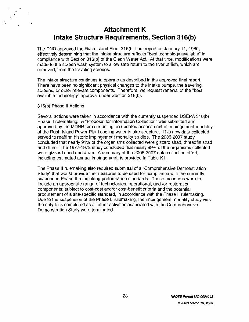
Attachment K Intake Structure Requirements, Section 31 6(b)
The DNR approved the Rush Island Plant 31 6(b) final report on January 11, 1980, effectively determining that the intake structure reflects "best technology available" in compliance with Section 31 6(b) of the Clean Water Act. At that time, modifications were made to the screen wash system to allow safe return to the river of fish, which are removed, from the traveling screens.
The intake structure continues to operate as described in the approved final report. There have been no significant physical changes to the intake pumps, the traveling screens, or other relevant components. Therefore, we request renewal of the "best available technology" approval under Section 31 6(b).
31 6(b) Phase II Actions
Several actions were taken in accordance with the currently suspended USEPA 31 6(b) Phase II rulemaking. A "Proposal for Information Collection" was submitted and approved by the MDNR for conducting an updated assessment of impingement mortality at the Rush Island Power Plant cooling water intake structure. This new data collected served to reaffirm historic impingement mortality studies. The 2006-2007 study concluded that nearly 91% of the organisms collected were gizzard shad, threadfin shad and drum. The 1977-1 978 study concluded that nearly 99% of the organisms collected were gizzard shad and drum. A summary of the 2006-2007 data collection effort, including estimated annual impingement, is provided in Table K1.
The Phase II rulemaking also required submittal of a "Comprehensive Demonstration Study" that would provide the measures to be used for compliance with the currently suspended Phase I I rulemaking performance standards. These measures were to include an appropriate range of technologies, operational, and lor restoration components; subject to cost-cost and/or cost-benefit criteria and the potential procurement of a site-specific standard, in accordance with the Phase II rulemaking. Due to the suspension of the Phase II rulemaking, the impingement mortality study was the only task completed as all other activities associated with the Comprehensive Demonstration Study were terminated.
NPDES Permit MO-0000043
Revised March 19,2009
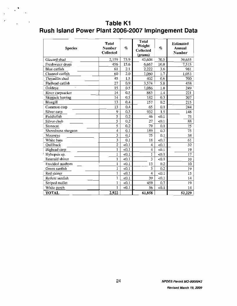
Table K1 Rush Island Power Plant 2006-2007 Impingement Data
NPDES Permit MO-0000043
Revised March 19,2009
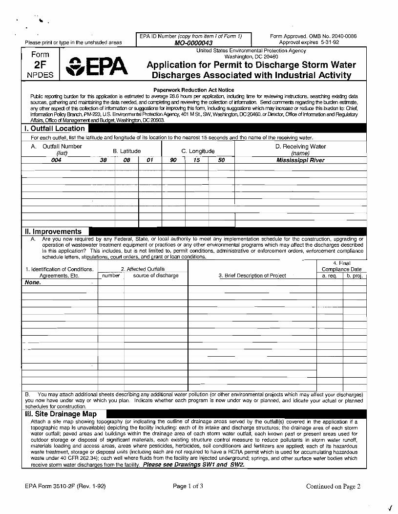
Form Approved. OMB No. 2040-0086
B. You may attach additional sheets describing any additional water pollution (or other environmental projects which may affect your discharges) you now have under way or which you plan. Indicate whether each program is now under way or planned, and idicate your actual or planned schedules for construction.
I l l . Site Drainage Map Attach a site map showing topography (or indicating the outline of drainage areas sewed by the outfall(s) covered in the application if a topographic map Is unavailable) depicting the facility including: each of its intake and discharge structures; the drainage area of each storm water outfall; paved areas and buildings within the drainage area of each storm water outfall, each known past or present areas used for outdoor storage or disposal of significant materials, each existing structure control measure to reduce pollutants in storm water runoff, materials loading and access areas, areas where pesticides, herbicides, soil conditioners and fertilizers are applied; each of its hazardous waste treatment, storage or disposal units (including each are not required to have a RCRA permit which is used for accumulating hazardous waste under 40 CFR 262.34); each well where fluids from the facility are injected underground; springs, and other surface water bodies which receive storm water discharges from the facility. Please see Drawings SW1 and SW2.
EPA Form 351 0-2F (Rev. 1 -92) Page 1 of 3 Continued on Page 2
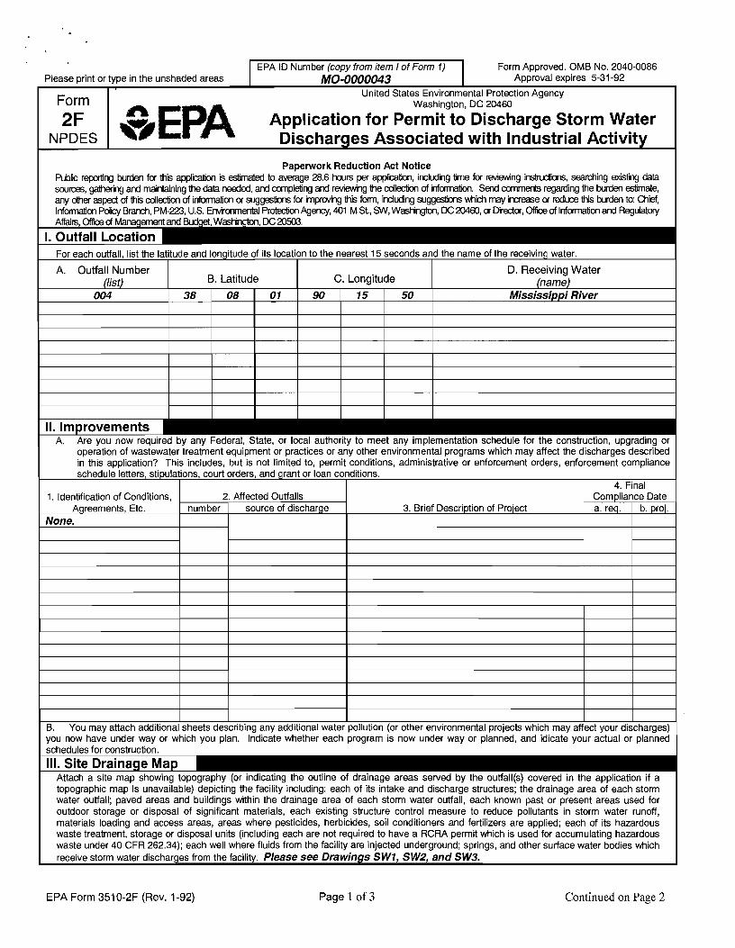
B. You may attach additional sheets describing any additional water pollution (or other environmental projects which may affect your discharges) you now have under way or which you plan. Indicate whether each program is now under way or planned, and idicate your actual or planned schedules for construction.
Ill. Site Drainage Map Attach a site map showing topography (or indicating the outline of drainage areas sewed by the outfall(s) covered in the application if a topographic map Is unavailable) depicting the facility including: each of its intake and discharge structures; the drainage area of each storm water outfall; paved areas and buildings within the drainage area of each storm water outfall, each known past or present areas used for outdoor storage or disposal of significant materials, each existing structure control measure to reduce pollutants in storm water runoff, materials loading and access areas, areas where pesticides, herbicides, soil conditioners and fertilizers are applied; each of its hazardous waste treatment, storage or disposal units (including each are not required to have a RCRA permit which is used for accumulating hazardous waste under 40 CFR 262.34); each well where fluids from the facility are injected underground; springs, and other surface water bodies which receive storm water discharges from the facility. Please see Drawings SWI, SW2, and SW3.
EPA Form 351 0-2F (Rev. 1-92) Page 1 of 3 Continued on Page 2
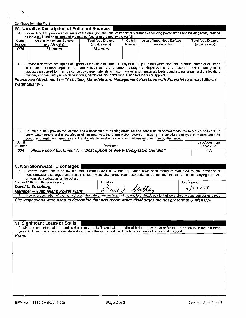
Continued from the Front
IV. Narrative Description of Pollutant Sources m- A. For each outfall, provide an estimate of the area (include units) of impervious surfaces (including paved areas and building roofs) drained
to the outfall, and an estimate of the total surface area drained by the outfall. Outfall I Area of lmoervious Surface I Total Area Drained 1 Outfall I Area of lm~ervious Surface I Total Area Drained
B. Provide a narrative description of significant materials that are currently or in the past three years have been treated, stored or disposed in a manner to allow exposure to storm water; method of treatment, storage, or disposal; past and present materials management practices employed to minimize contact by these materials with storm water runoff; materials loading and access areas; and the location, manner, and frequency in which pesticides, herbicides, soil conditioners, and fertilizers are applied.
Please see Attachment I - "Activities, Materials and Management Practices with Potential to Impact Storm Water Qualityy'.
- - .. ~ - - ~ . ~ . . . - - - - - - -
Number 1 (prohde units) 11 acres
C. For each outfall, provide the location and a description of existing structural and nonstructural control measures to reduce pollutants in storm water runoff; and a description of the treatment the storm water receives, including the schedule and type of maintenance for control and treatment measures and the ultimate disposal of any solid or fluid wastes other than by discharge.
Outfall I I List Codes from
~ ~
(provide units) 13 acres
I
V. Non Stormwater ~ischar~d-
Number 004
A. I certify under penalty of law that the outfall(s) covered by this application have been tested or evaluated for the presence of
Number
nonstormwater discharges, and that all nonstormwater discharges from these outfall(s) are identified in either an accompanying Form 2C
Treatment Please see Attachment A - "Description of Site & Designated Outfalls"
units)
Table 2F-1 4-A
VI. Significant Leaks or Spills Provide existing information regarding the history of significant leaks or spills of toxic or hazardous pollutants at the facility in the last three years, including the approximate date and location of the spill or leak, and the type and amount of material released.
None.
(provide units)
~ - or Form 2E application for the outfall.
EPA Form 351 0-2F (Rev. 1 -92)
Name of Official Title (type or print) David L. Strubberg,
Page 2 of 3
- -
Continued on Page 3
Signature
Bdb 4 Date Signed
Manager - Rush Island Power Plant 3 / 2 J'/U p
B. provide a description of the method used, the date of any testing, and the onsite drainage points that were directly observed during a test. Site inspections were used to determine that non-storm water discharges are not present at Outfall 004.
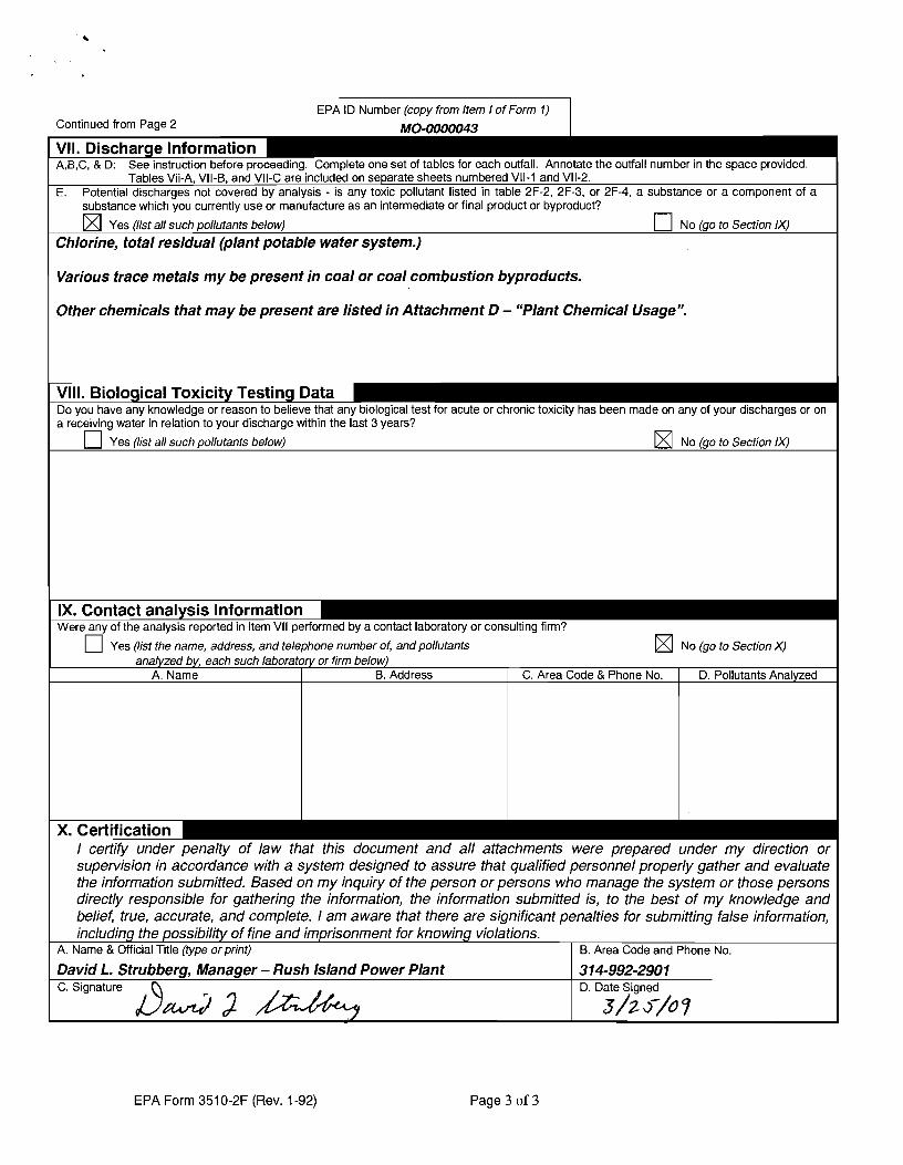
Continued from Page 2 EPA ID Number (copy from Item I of Form 1)
MO-nnnnndi,
A,B,C, & D: See instruction before proceeding. Complete one set of tables for each outfall. Annotate the outfall number in the space provided. Tables Vii-A, VII-B, and VII-C are included on separate sheets numbered VII-1 and Vll-2.
E. Potential discharges not covered by analysis - is any toxic pollutant listed in table 2F-2, 2F-3, or 2F-4, a substance or a component of a substance which you currently use or manufacture as an intermediate or final product or byproduct? - -
Yes (list all such pollutants below) U NO (go to section IX)
Chlorine, total residual (plant potable water system.)
Various trace metals my be present in coal or coal combustion byproducts.
Other chemicals that may be present are listed in Attachment D - "Plant Chemical Usage".
Do you have any knowledge or reason to believe that any biological test for acute or chronic toxicity has been made on any of your discharges or on a receiving water in relation to your discharge within the last 3 years?
Yes (list all such pollutants below) NO (go to section IX)
IX. Contact analysis Information - Were any of the analysis reported in item VII performed by a contact laboratory or consulting firm? - -
I certify under penalty of law that this document and all attachments were prepared under my direction or supervision in accordance with a system designed to assure that qualified personnel properly gather and evaluate the information submitted. Based on my inquiry of the person or persons who manage the system or those persons directly responsible for gathering the information, the information submitted is, to the best of my knowledge and belief, true, accurate, and complete. I am aware that there are siclnificant penalties for submittina false information,
U Yes (list the name, address, and telephone number of, and pollutants NO (go to Section X) analyzed by, each such laboratory or firm below)
- including the possibility of fine and imprisonment for knowing violations.
'
A. Name & Official Title (type orprint) I B. Area Code and Phone No.
A. Name
David L. Strubberg, Manager - Rush Island Power Plant 1 3 14-992-290 1
B. Address
EPA Form 351 0-2F (Rev. 1-92)
-. - C. Signature
Page 3 of 3
C. Area Code & Phone No.
D. Date Signed
D. Pollutants Analyzed
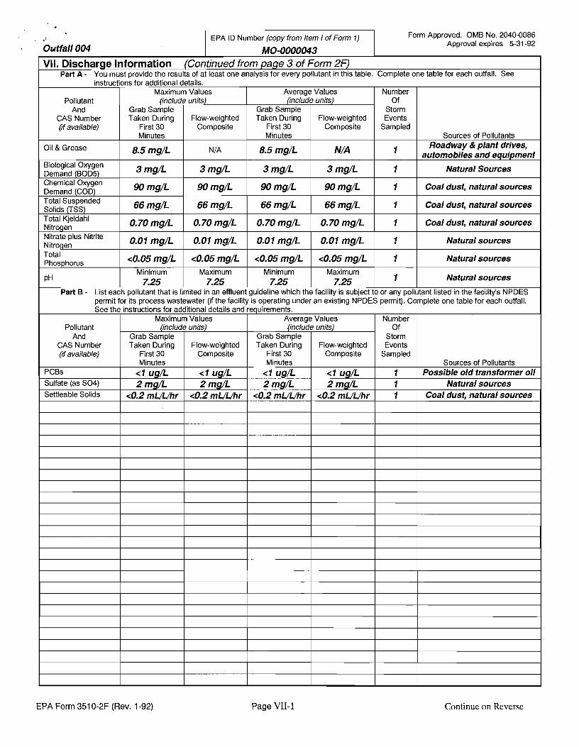
EPA Form 351 0-2F (Rev. 1-92) Page VII-1 Continue on Reverse
Form Approved. OMB No. 2040-0086 Approval expires 5-31 -92 Qwtfall004
EPA ID Number (copy from Item I of Form 1)
MQ-0000043 VII. Discharge Information (Continued from page 3 of Form 2F)
Part A - You must provide the results of at least one analysis for every pollutant in this table. Complete one table for each outfall. See
Number Of
Storm Events
Sampled
1
1
1
1
1
1
1 to or any
instructions
Pollutant And
CAS Number (if available)
Oil & Grease
Biological Oxygen Demand (BOD5) Chemical Oxygen Demand (COD) Total Suspended Solids (TSS) Total Kjeldahl Nitrogen Nitrate plus Nitrite Nitrogen Total Phosphorus
PH
Part B - List each
Sources of Pollutants Roadway & plant drives,
automobiles and equipment
Natural Sources
Coal dust, natural sources
Coal dust, natural sources
Coal dust, natural sources
Natural sources
Natural sources
Natural sources
pollutant listed in the facility's NPDES
Average Values
permit for its process wastewater (if the facility is operating under an existing NPDES permit). Complete one table for each outfall. See the instructions for additional details and requirements.
(include Grab Sample Taken During
First 30 Minutes
8.5 mg/L
3 mg/L
90 mg/L
66 mg/L
0.70 mg/L
0.01 mg/L
<O. 05 mg/L Minimum
7.25 guideline which the
for additional details. Maximum Values
units)
Flow-weighted Composite
N/A
3 mg/L
90 mg/L
66 mg/L
0.70 mg/L
0.01 mg/L
<0.05 mg/L Maximum
7.25 facility is subject
(include Grab Sample Taken During
First 30 Minutes
8.5 mg/L
3 mg/L
90 mg/L
66 mg/L
0.70 mg/L
0.01 mg/L
<O. 05 mg/L Minimum
7.25 pollutant that is
Pollutant And
CAS Number (if available)
PCBs Sulfate (as S04) Settleable Solids
units)
Flow-weighted Composite
NIA
3 mg/L
90 mg/L
66 mg/L
0.70 mg/L
0.01 mg/L
<O. 05 mg/L Maximum
7.25 limited in an effluent
Maximum Values (include units)
Average Values (include units)
Number Of
Storm Events
Sampled
1 1 1
Grab Sample Taken During
First 30 Minutes
< I ug/L 2 mg/L
<0.2 mUUhr
Grab Sample Taken During
First 30 Minutes
< I ug/L 2 mg/L
<0.2 mUUhr
Sources of Pollutants Possible old transformer oil
Natural sources Coal dust, natural sources
Flow-weighted Composite
< 1 ug/L 2 mg/L
<0.2 mUUhr
Flow-weighted Composite
<I ug/L 2 mg/L
<0.2 mUUhr
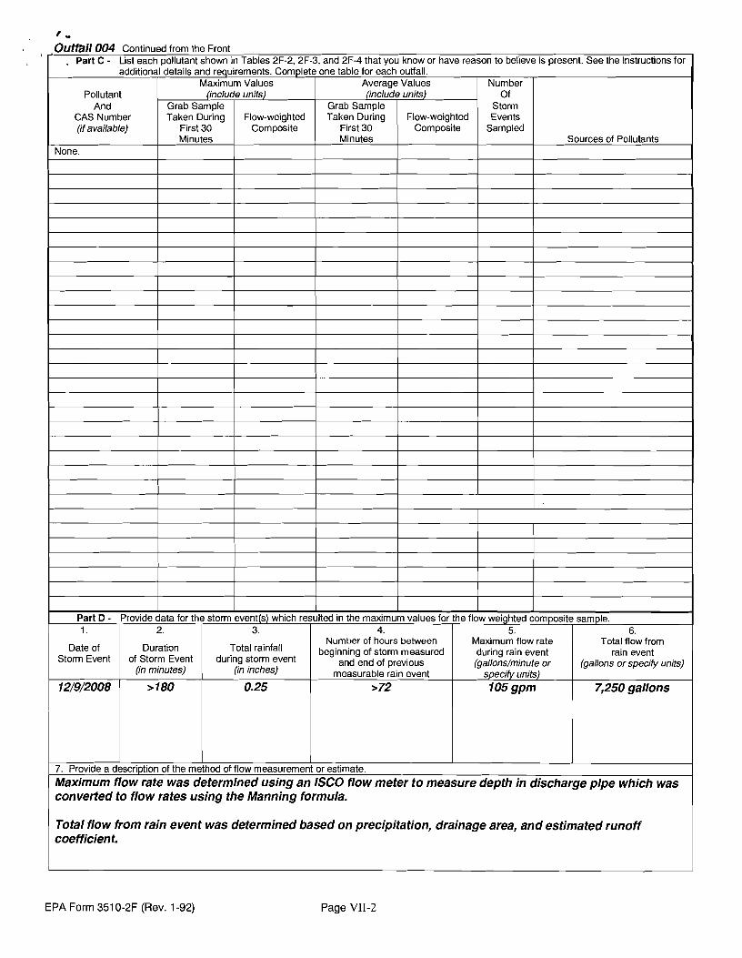
Total flow from rain event was determined based on precipitation, drainage area, and estimated runoff coefficient.
t " ,Outfall 004 Continued from the Front . Part C - List each pollutant shown in Tables 2F-2, 2F-3, and 2F-4 that you know or have reason to believe is present. See the instructions for
additional details and requirements. Complete one table for each outfall.
EPA Form 351 0-2F (Rev. 1-92) Page VII-2
Pollutant And
CAS Number (if available)
None.
Maximum Values (include units)
Part D - Provide data for the storm event(s) which resulted in the maximum values for the flow weighted composite sample.
Grab Sample Taken During
First 30 Minutes
Flow-weighted Composite
Average Values (include units)
1.
Date of Storm Event
12/9/2008
Number Of
Storm Events
Sampled
Grab Sample Taken During
First 30 Minutes
7. Provide a description of the method of flow measurement or estimate.
Maximum flow rate was determined using an ISCO flow meter to measure depth in discharge pipe which was converted to flow rates using the Manning formula.
4. Number of hours between
beginning of storm measured and end of previous
measurable rain event >72
Sources of Pollutants
Flow-weighted Composite
2.
Duration of Storm Event
(in minutes)
>I80
3.
Total rainfall during storm event
(in inches)
0.25
5. Maximum flow rate during rain event (gallons/minute or
specify units) 105 gpm
6. Total flow from
rain event (gallons or specify units)
7,250 gallons
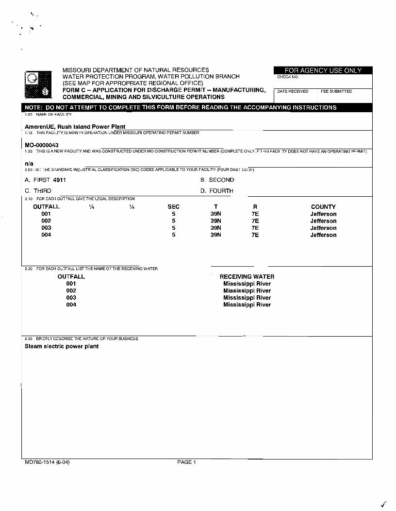
MISSOURI DEPARTMENT OF NATURAL RESOURCES WATER PROTECTION PROGRAM, WATER POLLUTION BRANCH (SEE MAP FOR APPROPRIATE REGIONAL OFFICE) FORM C -- APPLICA'I'ION FOR DlSCklARGE PERMIT -- MANUFACTURING, COMMERCIAL, MINING AND SlLVlCLlLTLlRE OPERATIONS
1 .OO NAME OF FACILITY
AmerenUE, Rush Island Power Plant 1.10 THlS FACILITY IS NOW IN OPERATION UNDER MISSOURI OPERATING PERMIT NUMBER
MO-0000043 1.20 THlS IS A NEW FACILITY AND WAS CONSTRUCTED UNDER MO CONSTRUCTION PERMIT NUMBER (COMPLETE ONLY IF THlS FACILITY DOES NOT HAVE AN OPERATING PERMIT).
nla 2.00 LlST THE STANDARD INDUSTRIAL CLASSIFICATION (SIC) CODES APPLICABLE TO YOUR FACILITY (FOUR DIGIT CODE)
A. FIRST 4911 B. SECOND I C. THIRD D. FOURTH 2.10 FOR EACH OUTFALL GIVE THE LEGAL DESCRIPTION
OUTFALL l/. '/a SEC T R COUNTY 001 5 39N 7E Jefferson 002 5 39N 7E Jefferson 003 5 39N 7E Jefferson 004 5 39N 7E Jefferson
2.20 FOR EACH OUTFALL LlST THE NAME OF THE RECEIVING WATER
OUTFALL RECEIVING WATER 001 Mississippi River 002 Mississippi River 003 Mississippi River 004 Mississippi River
2 30 BRIEFLY DESCRIBE THE NATURE OF YOUR BUSINESS
Steam electric power plant
I I M0780-1514 (6-04) PAGE 1
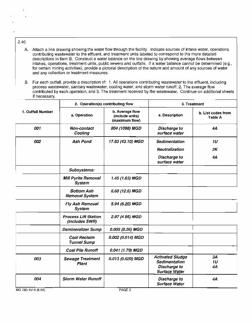
A. Attach a line drawing showing the water flow through the facility. Indicate sources of intake water, operations contributing wastewater to the effluent, and treatment units labeled to correspond to the more detailed descriptions in Item B. Construct a water balance on the line drawing by showing average flows between intakes, operations, treatment units, public sewers and outfalls. If a water balance cannot be determined (e.g., for certain mining activities), provide a pictorial description of the nature and amount of any sources of water and any collection or treatment measures.
B. For each outfall, provide a description of: 1. All operations contributing wastewater to the effluent, including process wastewater, sanitary wastewater, cooling water, and storm water runoff; 2. The average flow contributed by each operation; and 3. The treatment received by the wastewater. Continue on additional sheets if necessary.
2. Operation(s) contributing flow
Discharge to 4A I surface water I
3. Treatment
1. Outfall Number
Ash Pond 1 17.83(43.10)MGD I Sedimentation I
I I I
I I Neutralization I
a. Operation
Discharge to I s u h e water I Subsystems:
I I I I
b. Average flow (include units)
(maximum flow)
Bottom Ash 1 6.60 (12.6) MGD Removal System
a. Description
Mill Pyrite Removal 1 system
b. List codes from Table A
1.45 (1.63) MGD
1 I Demineralizer Sump 1 0.005 (0.26) MGD I I 1
Fly Ash Removal System
Process Lift Station (includes S WR)
Coal Reclaim I 0.002(0.014) MGD Tunnel Sump
5.94 (6.20) MGD
2.97 (4.95) MGD
1 I I I Surface Water I I
003
Coal Pile Runoff
Sewage Treatment Plant
004
0.041 (1.79) MGD
0.01 3 (0.020) MGD
MO 780-151 4 (6-04) PAGE 2
Storm Water Runoff
Activated Sludge Sedimentation Discharge to
Discharge to Surface Water
3A 1U 4A
4A
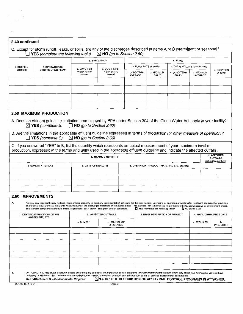
2.40 continued 1 C. Except for storm runoff, leaks, or spills, are any of the discharges described in Items A or B intermittent or seasonal? 1 YES (complete the folowing table) rn NO (go to Section 2.50)
2.50 MAXIMUM PRODUCTION
1. OUTFALL NUMBER
I A. Does an effluent guideline limitation promulgated by EPA under Section 304 of the Clean Water Act apply to your facility? YES (complete 6) NO (go to Section 2.60)
2.OPERATION(S) CONTRIBUTING FLOW
2.60 IMPROVEMENTS
B. Are the limitations in the applicable effluent guideline expressed in terms of production (or other measure of operation)? YES (complete C) (XI NO (go to Section 2.60)
C. If you answered "YES" to 6, list the quantity which represents an actual measurement of your maximum level of production, expressed in the terms and units used in the applicable effluent guideline and indicate the affected out-falls.
A. Are you now required by any Federal, State or local authority to meet any implementation schedule for the construction, upgrading or operation of wastewater treatment equipment or practices or any other environmental programs which may affect the discharges described in this application? This includes, but is not limited to, permit conditions, administrative or enforcement orders, f
1. IDENTIFICATION OF CONDITION, 2. AFFECTED OUTFALLS 3. BRIEF DESCRIPTION OF PROJECT 4. FINAL COMPLIANCE DATE AGREEMENT, ETC.
DISCHARGE
1. MAXIMUM QUANTITY
B. OPTIONAL - You may attach additional sheets describing any additional water pollution control programs (or other environmental projects which may effect your d~scharges) you now have underway or which you plan. Indicate whether each program is now underway or planned, and indicate your actual or planned schedules for construction.
See "Affachment G - Environmental Projects" [XJMARK "Xu IF DESCRIPTION OF ADDITIONAL CONTROL PROGRAMS IS AlTACHED. MO 780-1514 (6-04) PAGE 3
3. FREQUENCY
2. AFFECTED OUTFALLS
(list outfall numbers)
4. FLOW
a. DAYS PER WEEK(specW
average)
b. MONTHS PER YEAR
evwage)
a. QUANTITY PER DAY
I
c. DURATION (in days)
a. FLOW RATE (in MGD)
b. UNITS OF MEASURE
1. LONG TERM AVERAGE
b. TOTAL VOLUME (specrfy units)
c. OPERATION, PRODUCT, MATERIAL, ETC. (specrfy)
2. MAXIMUM DAILY
4. LONG TERM DAILY
3. MAXIMUM AVERAGE
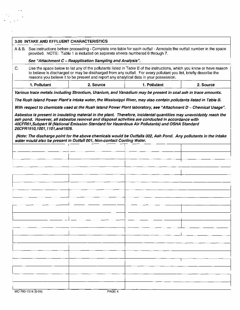
3.00 INTAKE AND EFFLUENT CHARACTERISTICS
A & B. See instructions before proceeding - Complete one table for each outfall - Annotate the outfall number in the space provided. IVOTE: Table 1 is included on separate sheets numbered 6 through 7.
See "Attachment C - Reapplication Sampling and Analysis".
Various trace metals including Strontium, Uranium, and Vanadium may be present in coal ash in trace amounts.
C. Use the space below to list any of the pollutants listed in Table B of the instructions, which you know or have reason to believe is discharged or may be discharged from any outfall. For every pollutant you list, briefly describe the reasons you believe it to be present and report any analytical data in your possession.
The Rush Island Power Plant's intake water, the Mississippi River, may also contain pollutants listed in Table B.
With respect to chemicals used at the Rush Island Power Plant laboratory, see "Attachment D - Chemical Usage".
1. Pollutant
Asbestos is present in insulating material in the plant. Therefore, incidental quantities may unavoidably reach the ash pond. However, all asbestos removal and disposal activities are conducted in accordance with 40CFR61,Subpar-t M (National Emission Standard for Hazardous Air Pollutants) and OSHA Standard 26CFR1910,1001,1101,and1926.
2. Source 1. Pollutant
(Note: The discharge point for the above chemicals would be Outfalls 002, Ash Pond. Any pollutants in the intake water would also be present in Outfall 001, Non-contact Cooling Water.
I I I
2. Source
MO 780-1 51 4 (6-04) PAGE 4
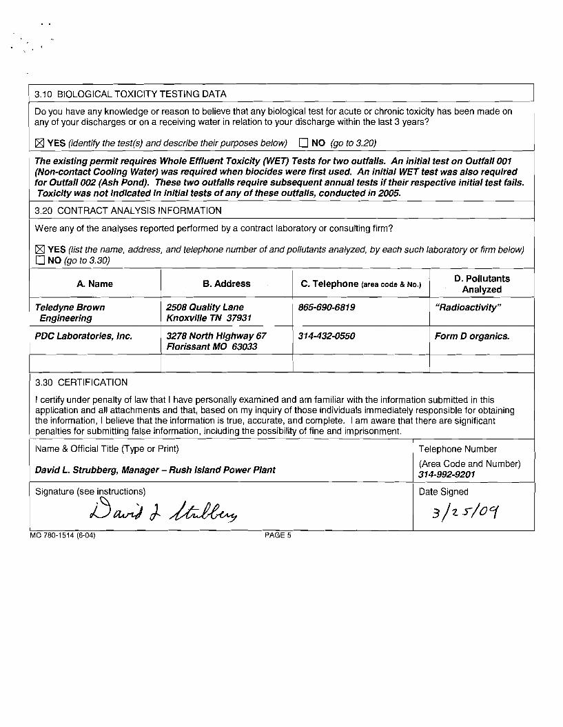
3.1 0 BIOLOGICAL TOXICITY TESTING DATA - -
any knowledge or reason to believe that any biological test for acute or chronic toxicity has been made on any of your discharges or on a receiving water in relation to your discharge within the last 3 years?
I [XI YES (identify the test(s) and describe their purposes below) NO (go to 3.20) 1 The existing permit requires Whole Effluent Toxicity (WET) Tests for two outfalls. An initial test on Outfall 001 (Non-contact Cooling Water) was required when biocides were first used. An initial WET test was also required for Outfall 002 (Ash Pond). These two outfalls require subsequent annual tests if their respective initial test fails.
1 Toxicity was not indicated in initial tests of any of these outfalls, conducted in 2005.
1 3.20 CONTRACT ANALYSIS INFORMATION 1 Were any of the analyses reported performed by a contract laboratory or consulting firm?
[XI YES (list the name, address, and telephone number of and pollutants analyzed, by each such laboratory or firm below) NO (go to 3.30)
A. Name
"Radioactivity" Teledyne Brown Engineering
B. Address
2508 Quality Lane Knoxville TN 37931
Form D organics. PDC Laboratories, Inc. 1
3.30 CERTIFICATION
C. Telephone (area code & NO.)
3278 North Highway 67 Florissant MO 63033
I certify under penalty of law that I have personally examined and am familiar with the information submitted in this application and all attachments and that, based on my inquiry of those individuals immediately responsible for obtaining the information, I believe that the information is true, accurate, and complete. I am aware that there are significant penalties for submitting false information, including the possibility of fine and imprisonment.
Name & Official Title (Type or Print) 1 Telephone Number
D. Pollutants Analyzed
David L. Strubberg, Manager - Rush Island Power Plant (Area Code and Number) 31 4-992-9201
1 Signature (see i?structions) Date Signed
3 / 2 4 0 7 I I I MO 780-1514 (6-04) PAGE 5
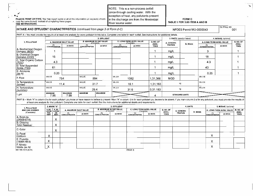
NOTE: This is a non-process outfall
z (once-through cooling water. With the * .b exception of heat, any pollutants present
PLEASE PRINT ORTYPE. YOU may report some or all of this ~nformation on separate sheets in the discharge are from the Mississippi FORM C (use the same format) instead of completing these pages SEE INSTRUCTIONS. River source water. TABLE 1 FOR 3.00 ITEM A AND B
INTAKE AND EFFLUENT CHARACTERISTICS (continued from page 3 of Form 2-C) NPDES Permit MO-0000043
PART A -You must provide the results of at least one analysis for every pollutant in this table. Complete one table for each outfall. See instructions for additional detarls.
PART B - Mark "X" in column 2-a for each pollutant you know or have reason to believe is present. Mark "X" in column 2-b for each pollutant you believe to be absent. If you mark column 2-a for any pollutant, you must provide the results ot at least one analysis for that pollutant. Complete one table for each outfall. See the instruct~ons for additional details and requirements.
2. MARK "X" 3. EFFLUENT 1. POLLUTANT
AND CAS NUMBER l available
MO 780-1514 (6-04) PAGE 6
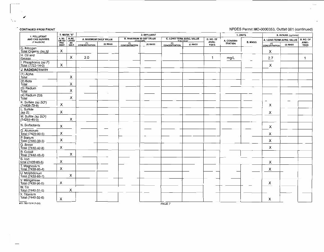
CONTINUED FROM FRONT NPDES Permit MO-0000353, Outfall O O I (continued)
(4) Radium 226 Total K. Sulfate (as SO) (1 4808-79-8) L. Sulfide (as S) M. Sulfite (as SO) (1 4265-45-3)
N. Surfactants
0. Aluminum Total (7429-90-5) P. Barium Total (7440-39-3) Q. Boron Total (7440-42-8) R. Cobalt Total (7440-48-4) S. Iron total (7439-89-6) T. Magnesium Total (7439-95-4) U. Molybdenum Total (7439-98-7) V. Manganese Total (7439-96-5) W. Tin Total (7440-31 -5) X. Titanium Total (7440-32-6)
MO 780-1514 (6-04)
x X
X
X
X
x x x
- x
X
X
X
x x x
x X
x x
x
X
x X
! f E E ~ = PAGE 7
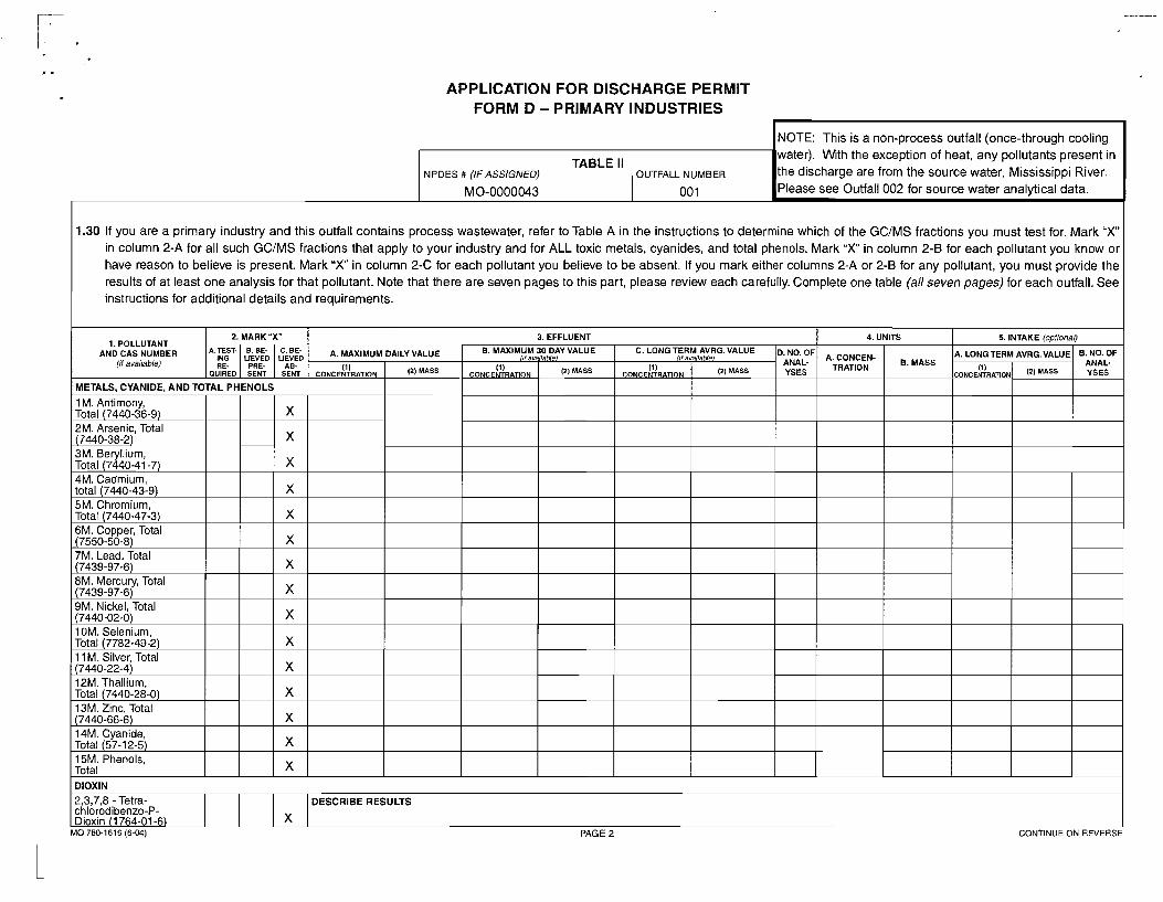
APPLICATION FOR DISCHARGE PERMIT FORM D - PRIMARY INDUSTRIES
NOTE: This is a non-process outfall (once-through cooling
TABLE II water). With the exception of heat, any pollutants present in
NPDES # (IFASSIGNED) OUTFALL NUMBER the discharge are from the source water, Mississippi River.
1.30 If you are a primary industry and this outfall contains process wastewater, refer to Table A in the instructions to determine which of the GCJMS fractions you must test for. Mark " X in column 2-A for all such GCJMS fractions that apply to your industry and for ALL toxic metals, cyanides, and total phenols. Mark " X in column 2-B for each pollutant you know or have reason to believe is present. Mark " X in column 2-C for each pollutant you believe to be absent. If you mark either columns 2-A or 2-B for any pollutant, you must provide the results of at least one analysis for that pollutant. Note that there are seven pages to this part, please review each carefully. Complete one table (all seven pages) for each outfall. See instructions for additional details and requirements.
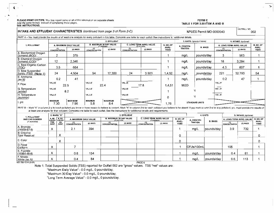
PLEASE PRINT OR TYPE. You may report some or all of this information on separate sheets (use the same format) instead of completing these pages. SEE INSTRUCTIONS.
FORM C TABLE 1 FOR 3.00 ITEM A AND B
OUTFALL NO. I INTAKE AND EFFLUENT CHARACTERISTICS (continued from page 3 of Form 2-C) NPDES Permit MO-0000043 I 002 1 I PART A -You must provide the results of at least one analysis for everv ~ollutant in this table. Complete one table for each outfall. See instructions for additional details. I I I 2. EFFLUENT 1 3. UNITS (specity if blank) I 4. INTAKE lo~tional) I
PART B - Mark " X in column 2-a for each pollutant you know or have reason to believe is present. Mark "X" in column 2-b for each pollutant you believe to be absent. If you mark column 2-a for any pollutant, you must provide the results of at least one analysis for that pollutant. Complete one table for each outfall. See the instructions for additional details and requirements.
1. POLLUTANT
A. Biochemical Oxygen Demand (BOD) B. Chemical Oxygen Demand (COD) C. To ta l Organic Carbon (TOC) D. Total Suspended Solids (TSS) (Note 1) E. Ammonia
_(as N)
F. F l o w
G. Temperature (winter) H. T e m p e r a t u r e
I (summer) l 1 0 1 *C l I I VALUE VALUE
1. POLLUTANT AND CAS NUMBER
(il available)
MO 780-1514 (6-04) PAGE 6
Note 1: Total Suspended Solids (TSS) reported for Outfall 002 are "gross" values. TSS "net" values are: "Maximum Daily Value" - 0.0 mglL, 0 poundslday; "Maximum 30 Day Value" - 0.0 mglL, 0 poundslday; "Long Term Average Value" - 0.0 mglL, 0 poundslday.
D. Fecal Coliform E. Fluoride (1 6984-48-8) F. Ni t rate- Nitrite /a.c N )
C. Color I I X I I I I I I 1 0 1 I I I 1 0 1
A. CONCEN- TRATION
mglL
mglL
mglL
mg1L
mglL
MGD
A. MAXIMUM DAILY VALUE
2. MARK "X"
X
X
X
B. MASS
poundslday
poundslday
poundslday
poundslday
poundslday
D$dfF YSES
1
1
1
1,4,52
1
1,4,51
1
6. MAXIMUM 30 DAY VALUE
(1) CONCENTRATION
2
12
3.5
24
0.2
C. LONG TERM AVRG.VALUE
Ai:FD PRE- SENT
X
" c
8. NO. OF ANAL- YSES
1
1
1
54
1
((1
(1) CONCENTRATION
94
(')
375
2,346
664
4,504
4 1
Of (1)
CONCENTRATION
24
. . . A. LONG TERM AVRG. VALUE
&:FD AB-
SENT
X
3. EFFLUENT
7
0.8
0.4
avaiiablei
('I
17,300
VALUE 22.5
VALUE
8.2
ava,!abiei
(')
3,503
(1) CONCENTRATION
3
18
4.3
22 1
0.2 VALUE
22.4 VALUE
VALUE 17.8
VALUE
('I
563
3,284
807
32,793
47
4. UNITS
154
84
VALUE
VALUE
A. CONCEN- TRATION
mglL
5. INTAKE (optional)
A. MAXIMUM DAILY VALUE B, MASS
poundslday
D$ny ySES
1
0
6. MAXIMUM /if uvailetdel 30 DAY VALUE C. LONG TERM AVRG. VALUE (if availvbiel
(1) CONCENTRATION
2.1
1
1
1
B. NO. OF ANAL- YSES
1
0
(11 CONCENTRATION
(1) CONCENTRATION 1') MASS
394
A. LONG TERM AVRG. VALUE
(') (') MASS (1) CONCENTRATION
3.9
CFUsllOOmL
mglL
ma1L
(') MASS
732
poundslday
ooundsldav
105
0.4
0.6
81
113
1
1
1
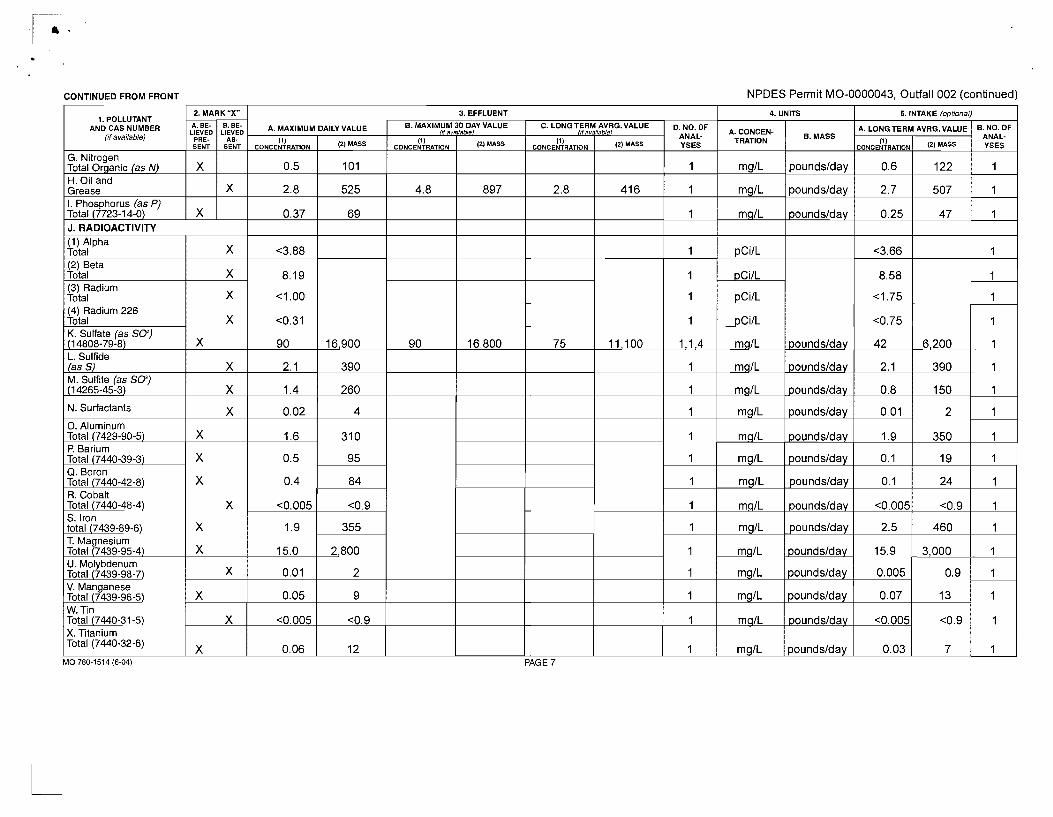
CONTINUED FROM FRONT NPDES Permit MO-0000043, Outfall 002 (continued)
3. EFFLUENT 1. POLLUTANT
AND CAS NUMBER if available
MO 780-1514 (6-04) PAGE 7
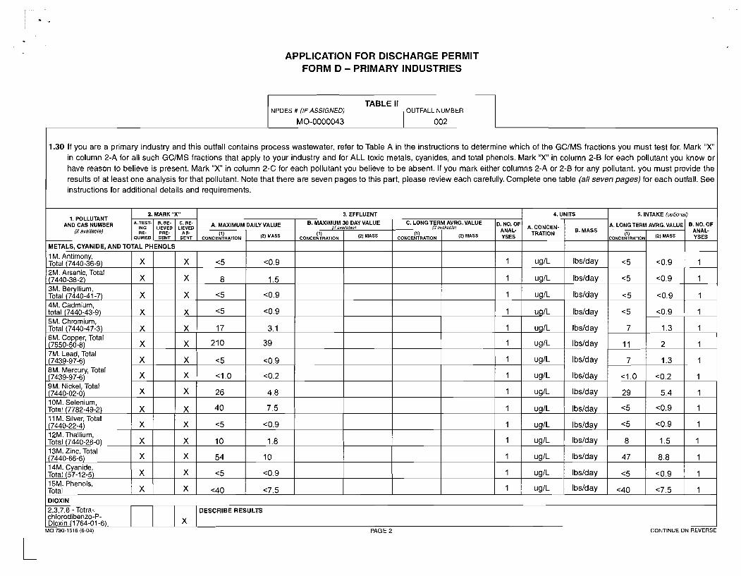
APPLICATION FOR DISCHARGE PERMIT FORM D - PRIMARY INDUSTRIES
TABLE II NPDES # (IFASSIGNED) , OUTFALL NUMBER
MO-0000043 002
1.30 If you are a primary industry and this outfall contains process wastewater, refer to Table A in the instructions to determine which of the GClMS fractions you must test for. Mark " X in column 2-A for all such GClMS fractions that apply to your industry and for ALL toxic metals, cyanides, and total phenols. Mark "X" in column 2-8 for each pollutant you know or have reason to believe is present. Mark " X in column 2-C for each pollutant you believe to be absent. If you mark either columns 2-A or 2-8 for any pollutant, you must provide the results of at least one analysis for that pollutant. Note that there are seven pages to this part, please review each carefully. Complete one table (all seven pages) for each outfall. See instructions for additional details and requirements.
1 CONTINUE ON REVERSE
2,3,7,8 - Tetra-. chlorodibenzo-P- Dioxin (1 764-01 -6)
MO 780-1516 (6-04) PAGE 2 x
DESCRIBE RESULTS
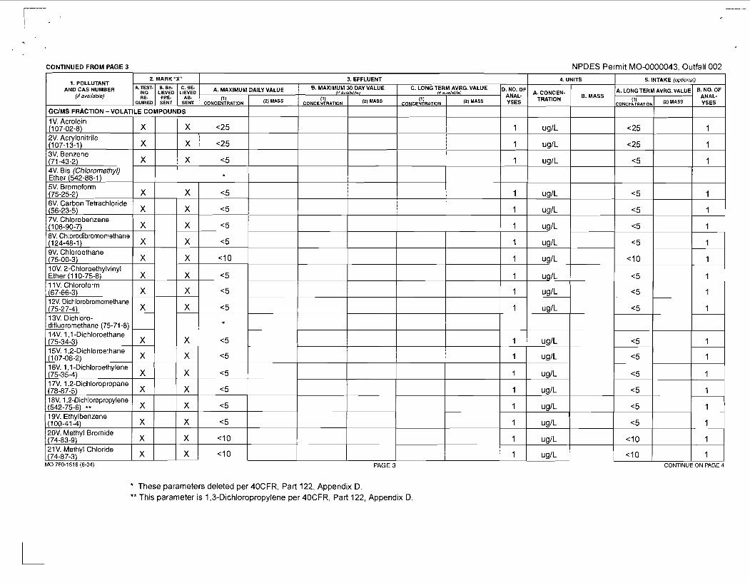
CONTINUED FROM PAGE 3 NPDES Permit MO-0000043. Outfall 002
These parameters deleted per 40CFR, Part 122, Appendix D. ** This parameter is 1,3-Dichloropropylene per 40CFR, Part 122, Appendix D
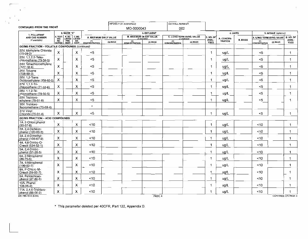
CONTINUED FROM THE FRONT NPDES # (IFASSIGNED) OUTFALL NUMBER
MO-0000043 1 002 2. MARK "X" 3. EFFLUENT 4. UNITS 5. INTAKE (opt~onal)
1. POLLUTANT AND CAS NUMBER :iFE; A. MAXIMUM DAILY VALUE B. MAXIMUM 30 DAY VALUE C. LONG TERM AVRG. VALUE (trriva~laM81 / I / availrible) Dn","dfF A. CONCEN- B, MASS
A. LONG TERM AVRG.VALUE B. NO. OF (!I avarlable) RE- PRE- AB- (1) (1) (3) YSES TRATION ANAL-
QUIRE0 SENT SENT CONCENTRATION / (') MASS CONCENTRATION 1 (') MASS CONCENTRATION ( (') MASS
GClMS FRACTION -VOLATILE COMPOUNDS (continued) I
9A. Pentachloro- phenol (87-86-5) X X < I0 1 uglL <I0 1
* This parameter deleted per 40CFR, Part 122, Appendix D.
10A. Phenol 108-95-2) 11A. 2,4.6-Trichloro- phenol (88-06-2)
MO 780-1 516 (6-04) PAGE 4 CONTINUE ON PAGE 5
X
x X
x <IO
< l o -
I
1
u ~ I L
- ug/L
<I0
< l o
I
1
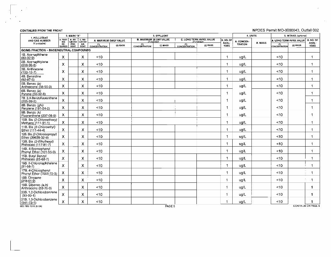
CONTINUED FROMTHE FRONT NPDES Permit MO-0000043, Outfall 002
MO 780-1 51 6 (6-04) PAGE 5 CONTINUE ON PAGE 6
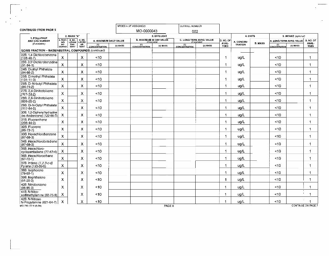
CONTINUED FROM PAGE 5
2. MARK "X" 3. EFFLUENT 4. UNITS 5. INTAKE (optional) 1. POLLUTANT
AND CAS NUMBER ii!& A. MAXIMUM DAILY VALUE 8. MAXIMUM 30 DAY VALUE C. LONG TERM AVRG. VALUE Rf availablel Of avsilableJ Dh","dfF A. CONCEN-
B, MASS A. LONG TERM AVRG.VALUE 6. NO. OF
(if available) RE- PRE- AB- (1) (1) (1) YSES TRATION ANAL-
QUIRED SENT SENT CONCENTRATION 1 (') CONCENTRATION 1 (') CONCENTRATION 1 (')
GCIMS FRACTION - BASEINEUTRAL COMPOUNDS (continued) I
NPDES # (IFASSIGNED)
MO-0000043
OUTFALL NUMBER
002
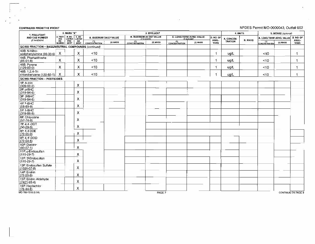
CONTINUED FROMTHE FRONT NPDES Permit MO-0000043, Outfall 002
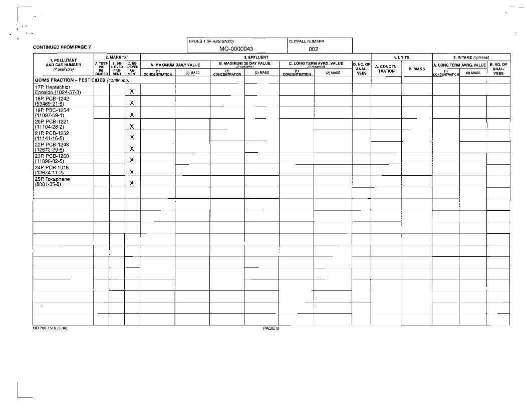
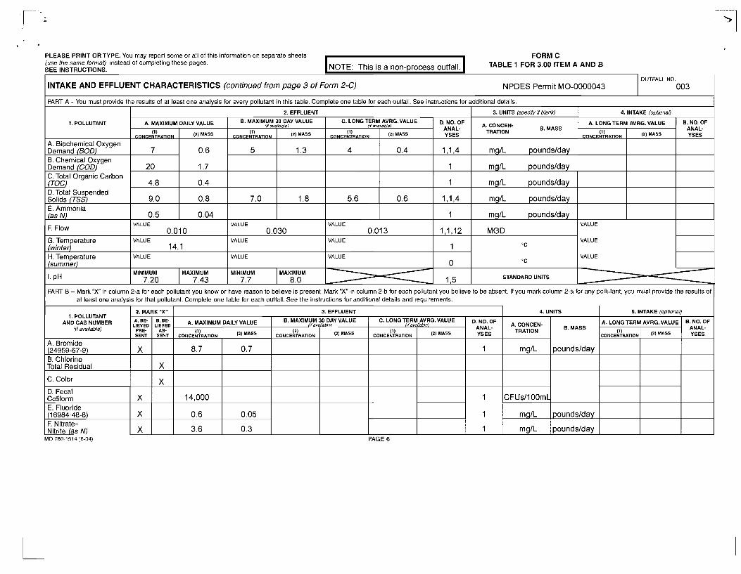
PART B - Mark "X" in column 2-a for each pollutant you know or have reason to believe is present. Mark X" in column 2-b for each pollutant you believe to be absent. If you mark column 2-a for any pollutant, you must provide the results of I at least one analvsis for that pollutant. Complete one table for each outfall. See the instructions for additional details and rerurements.
I .
PLEASE PRINT OR TYPE. You may report some or all of this information on separate sheets FORM C (use the same format) instead of completing these pages. SEE INSTRUCTIONS. NOTE: This is a non-process outfall. TABLE 1 FOR 3.00 ITEM A AND B
INTAKE AND EFFLUENT CHARACTERISTICS (continued from page 3 of Form 2-C) NPDES Permit MO-0000043
M 0 780-1514 (6-04) PAGE 6
OUTFALL NO.
003
1. POLLUTANT AND CAS NUMBER
(if available)
A. Bromide (24959-67-9) B. Chlorine Total Residual
C. Color
D. Fecal Coliform E. Fluoride (1 6984-48-8) F. Nitrate- Nitrite (as N)
PART A -You must provide the
1. POLLUTANT
A. Biochemical Oxygen Demand (BOD) B. Chemical Oxygen Demand (COD) C. Total Organic Carbon (TOC) D. Total Suspended Solids (TSS) E. Ammonia (as N)
F. Flow
G. Temperature (winter) H. Temperature (summer)
2. MARK "X"
I. pH d
1,5 STANDARD UNITS
ik!:D PRE- SENT
X
X
X
X
B. NO. OF ANAL- YSES
-C
4. INTAKE (optional)
A. LONG TERM AVRG. VALUE
3. EFFLUENT
iL!:D AB-
SENT
X
X
results of at least one analysis for every pollutant in this table. Complete one table for each outfall. See instructions for
(1) CONCENTRATION
additional details.
3. UNITS (specify if blank)
(') '"'
4. UNITS
A. MAXIMUM DAILY VALUE
A. CONCEN- TRATION
mglL
mglL
mglL
mglL
mglL
MGD
A. MAXIMUM DAILY VALUE
VALUE
VALUE
VALUE
A. CONCEN- TRATION
mglL
CFUsllOOmL
mg1L
mglL
5. INTAKE (oplional)
(1) CONCENTRATION
8.7
14,000
0.6
3.6
B. MASS
poundslday
poundslday
poundslday
poundslday
poundslday
(1) CONCENTRATION
7
20
4.8
9.0
0.5
B, MASS
poundslday
poundslday
poundslday
(') MASS
0.7
0.05
0.3
8. MAXIMUM nf avaiiatdel 30 DAY VALUE
"C
"C
(') '*"
0.6
1.7
0.4
0.8
0.04
2. EFFLUENT
B. MAXIMUM 30 DAY VALUE
8. NO. OF ANAL- YSES (1)
CONCENTRATION
A. LONG TERM AVRG. VALUE
VALUE 0.010
VALUE 14.1
VALUE
(if (1)
CONCENTRATION
5
7.0
Di\:fF YSES
1
1
1
1
(') '*" /if
(1) CONCENTRATION
D$:fF YSES
1,1,4
1
1
1 , IA
1
1,1,12
1
0 -
C. LONG TERM AVRG. VALUE availiible)
") '*"
1.3
1.8
svailabl~)
(') '"'
I,f (1)
CONCENTRATION
4
5.6
VALUE 0.030
VALUE
VALUE
avaiiablel
(2) '*"
0.4
0.6
C. LONG TERM AVRG. VALUE
VALUE 0.013
VALUE
VALUE
(1) CONCENTRATION (2) '*"
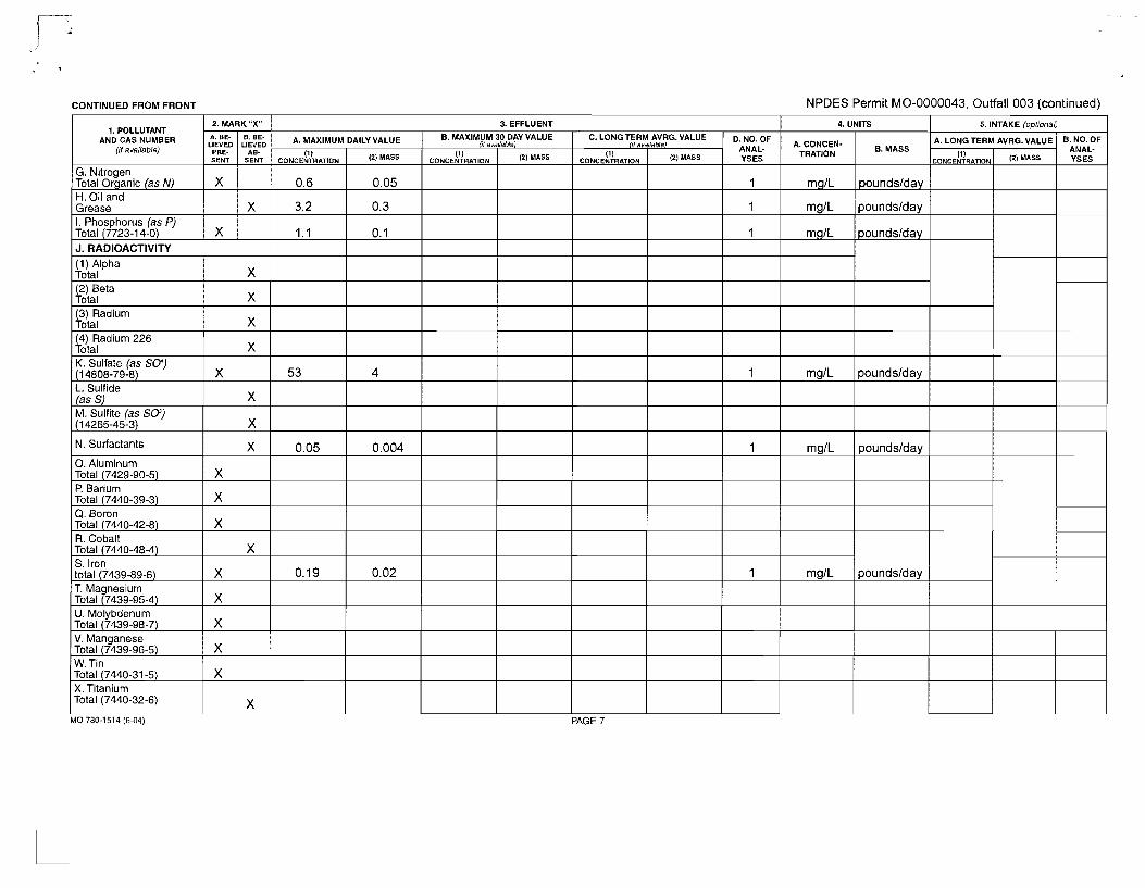
CONTINUED FROM FRONT NPDES Permit MO-0000043, Outfall 003 (continued)
MO 780-1514 (6-04) PAGE 7
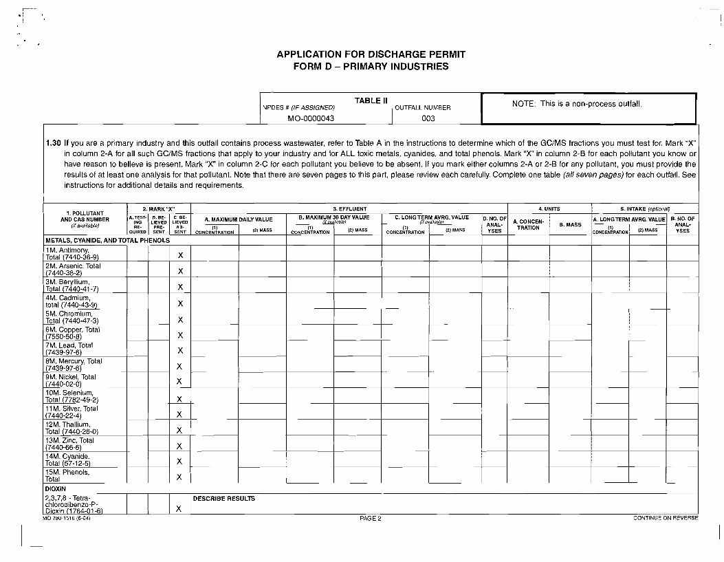
APPLICATION FOR DISCHARGE PERMIT FORM D - PRIMARY INDUSTRIES
1.30 If you are a primary industry and this outfall contains process wastewater, refer to Table A in the instructions to determine which of the GCIMS fractions you must test for. Mark " X in column 2-A for all such GCIMS fractions that apply to your industry and for ALL toxic metals, cyanides, and total phenols. Mark " X in column 2-6 for each pollutant you know or have reason to believe is present. Mark " X in column 2-C for each pollutant you believe to be absent. If you mark either columns 2-A or 2-8 for any pollutant, you must provide the results of at least one analysis for that pollutant. Note that there are seven pages to this part, please review each carefully. Complete one table (all seven pages) for each outfall. See instructions for additional details and requirements.
NOTE: This is a non-process outfall. TABLE II NPDES # (IF ASSIGNED) OUTFALL NUMBER
MO-0000043
1. POLLUTANT AND CAS NUMBER
(if available)
1 DIOXIN I
003
METALS, CYANIDE, AND TOTAL
Total (7440-36-9) 2M. Arsenic, Total (7440-38-2) 3M. Beryllium, Total (7440-41 -7) 4M. Cadmium, total (7440-43-9) 5M. Chromium. Total (7440-47-3) 6M. Copper, Total (7550-50-8) 7M. Lead, Total (7439-97-6) 8M. Mercury, Total (7439-97-6) 9M. Nickel, Total (7440-02-0) 10M. Selenium, Total (7782-49-2) 11 M. Silver, Total (7440-22-4) 12M. Thallium, Total (7440-28-0) 13M. Zinc, Total (7440-66-6) 14M. Cyanide, Total (57-1 2-5) 15M. Phenols, Tntal
(2.3,7,8 - Tetra- I I I I DESCRIBE RESULTS I
2. MARK "X"
PHENOLS
A.TES% ING RE-
QUIRED
X
X
X
X
X
X
X
X
X
X
X
X
X
X
x
chlorodibenzo-P- Dioxin (1764-01 -6)
3. EFFLUENT
X
A. MAXIMUM DAILY VALUE B. BE- LIEVED
PRE- SENT
MO 780-1516 (6-04) PAGE 2 I
CONTINUE ON REVERSE
4. UNITS
C. BE- LIEVED
AB- SENT
A. CONCEN- TRATION
B. MAXIMUM 30 DAY VALUE ( r f avai!able)
5 . INTAKE (optional)
B, MASS C. LONGTERM AVRG.VALUE
fif available1 (1) (1) (1)
CONCENTRATION 1 ('I MASS I CONCENTRATION I ('I MASS I CONCENTRATION 1 ('I MASS
A. LONGTERM AVRG.VALUE ( 0
CONCENTRATaNl (')
DcOALr)F YSES
B. NO. OF ANAL- YSES
*.- + MISSOURI DEPARTMENT OF NATURAL RESOURCES WATER PROTECTION PROGRAM, WATER POLLUTION BRANCH (SEE MAP FOR APPROPRIATE REGIONAL OFFICE)
k @ FORM D - APPLICATION FOR DISCHARGE PERMIT - DATE RECEIVED 1 FEE SUBMITTED
I 1 00 NAME OF FACILITY I AmerenUE Rush Island Power Plant
1.10 THIS FACILITY IS NOW IN OPERATION UNDER MISSOURI OPERATING PERMIT NUMBER
MO - 0000043
1.20 THIS IS A NEW FACILITY AND WAS CONSTRUCTED UNDER MISSOURI CONSTRUCTION PERMIT NUMBER (COMPLETE ONLY IFTHIS FACILITY DOES NOT HAVE AN OPERATING PERMIT).
Not applicable.
This form is to be filled out in addition to forms A and C "Application for Discharge Permit" for the Primary Industries listed below:
INDUSTRY CATEGORY
Adhesives and sealants
Aluminum forming
Auto and other laundries
Battery manufacturing
Coal mining
Coil coating
Copper forming
Electric and electronic compounds
Electroplating
Explosives manufacturing
Foundries
Gum and wood chemicals
Ore mining
Organic chemicals manufacturing
Paint and ink formulation
Pesticides
Petroleum refining
Pharmaceutical preparations
Photographic equipment and supplies
Plastic and synthetic materials manufacturing
Plastic processing
Porcelain enameling
Printing and publishing
Pulp and paperboard mills
I Inorganic chemicals manufacturing Rubber processing I Iron and steel manufacturing
Leather tanning and finishing
Mechanical products manufacturing
Nonferrous metals manufacturing
Soap and detergent manufacturing
Steam electric power plants
Textile mills
Timber products processing
LIST DIN ITEM 1.30 A SUBSTANCE OR A COMPONENT OF A SUBSTANCE WHICHYOU DO OR EXPECTTHATYOU WlLL OVER THE NEXT FIVEYEARS USE OR MANUFACTURE AS AN INTERMEDIATE OR FINAL PRODUCT OR BYPRODUCT'
YES (LIST ALL SUCH POLLUTANTS BELOW) NO (GO TO 8 )
Various trace metals may be present in coal or coal ash.
With respect to chemicals used in the Plant laboratory and solvents used for equipment maintenance and/or lubrication, see "Attachment D - Chemical Usage".
B. ARE YOUR OPERATIONS SUCH THAT YOUR RAW MATERIALS, PROCESSES OR PRODUCTS CAN REASONABLY BE EXPECTED TO VARY SO THAT YOUR DISCHARGES OF POLLUTANTS MAY DURING THE NEXT FlVE YEARS EXCEED TWO TIMES THE MAXIMUM VALUES REPORTED IN ITEM 1.30?
YES (COMPLETE C BELOWJ NO (GO TO SECTION 3.00)
C. IFYOU ANSWERED "YES"T0 ITEM B, EXPLAIN BELOW AND DESCRIBE IN DETAILTHE SOURCES AND EXPECTED LEVELS OF SUCH POLLUTANTSTHATYOU ANTICIPATE WlLL BE DISCHARGED FROM EACH OUTFALL OVER THE NEXT FlVE YEARS, TO THE BEST OFYOUR ABILITY AT THlS TIME. CONTINUE ON ADDITIONAL SHEETS IF YOU NEED MORE SPACE.
Variations or changes in coal supply or usage may affect Outfall 002 (Ash Pond). A different fuel supply could result in variations in ash content, characteristics, or leachability, which may result in changes of pollutant levels greater than a factor of two.
Waste streams can also be expected to exhibit variability, not as the result of varying raw material, processes, or products but rather as a result of varying influent water quality. Variability in intake water quality due to the effects of rainfall, runoff, and/or upstream pollutant discharges might cause discharge values on a gross basis to exceed two times the maximum values reported in Item 1.30.
3.00 CONTRACT ANALYSIS INFORMATION
14.00 CERTIFICATION I I
1 WERE ANY OFTHE ANALYSES REPORTED IN 1.30 PERFORMED BY A CONTRACT LABORATORY OR CONSULTING FIRM?
YES (LISTTHE NAME, ADDRESS. AND TELEPHONE NUMBER OF; AND ANALYZED BY; EACH SUCH LABORATORY OR FIRM BELOWJ NO (GO TO 4 00)
A. NAME
PDC Laboratories, Incorporated
I CERTIFY UNDER PENALTY OF LAW THAT I HAVE PERSONALLY EXAMINED AND AM FAMILIAR WITH THE INFORMATION SUBMITTED IN THlS APPLICATION AND ALL ATTACHMENTS AND THAT, BASED ON MY INQUIRY OF THOSE INDIVIDUALS IMMEDIATELY RESPONSIBLE FOR OBTAINING THE INFORMATION, I BELIEVE THAT THE INFORMATION IS TRUE, ACCURATE AND COMPLETE. I AM AWARE THAT THERE ARE SIGNIFICANT PENALTIES FOR SUBMITTING FALSE INFORMATION, INCLUDING THE POSSIBILITY OF FINE AND IMPRISONMENT. NAME AND OFFICIAL TITLE ( N P E OR PRINT)
David L. Strubberg - Manager, Rush Island Power Plant SIGNATURE
8. ADDRESS
3278 North Highway 67 Florissant MO 63033
PHONE NUMBER (AREA CODE AND NUMBER
31 4-992-9201
MO 780-1516 (6-04) PAGE 9
I
C.TELEPHONE (area code andnumber1
31 4-432-0550
D. POLLUTANTS ANALYZED (IistJ
All Form D except metals
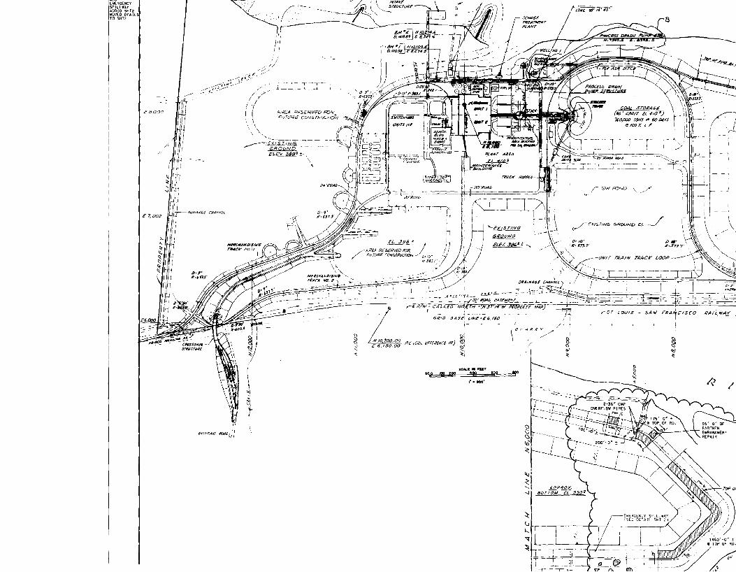
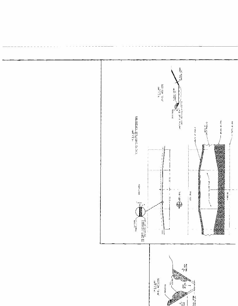


![li:11 I MISSOURI~[§] li:11 MISSOURI fil I DEPARTMENT OF L_gj ~ NATURAL RESOURCES Air Pollution Control Program PART 70 PERMIT TO OPERA TE Under the authority of RSMo 643 and the Federal](https://img.pdfslide.net/doc/110x75/5e8f7b6323c1d264350cc794/li11-i-missouri-li11-missouri-fil-i-department-of-lgj-natural-resources.jpg)