Embed Size (px)
Citation preview
1
Public Service Electric and Gas Company
Interconnection Requirements for Small ScaleDistributed Generation Equipment
APPLICATION PROCESS, INTERCONNECTION REQUIREMENTS AND LICENSEFOR NEW DISTRIBUTED GENERATORS, CONNECTED IN PARALLEL WITH
PRIMARY DISTRIBUTION CIRCUITS AND CUSTOMER SECONDARY SERVICES
ANY FORM OF CUSTOMER OWNED GENERATIONINTERCONNECTED WITH THE PSE&G SYSTEM MUST COMPLYWITH THE APPLICATION PROCESS HEREIN, BE REVIEWED BYPSE&G, AND RECEIVE THE EXPRESSED CONSENT OF PSE&GIN WRITING WITH AN APPROVED APPLICATION BEFORE ANY
INTERCONNECTION AND PARALLEL OPERATION BEGINS
March 11, 2002
Generation that cannot operate in parallel with PSE&G’ssystem is not subject to these requirements.
PSE&G Delivery Asset Management

2
Table of Contents
1.0 General
2.0 Scope
3.0 Application Process
4.0. Interconnection Requirements4.1.0 Design Requirements
4.1.1 Common4.1.2 Synchronous Generators4.1.3 Induction Generators4.1.4 DC Inverters
4.2 Metering4.2.1 Net Metering
4.3 Grounding
4.4 Operating Requirements
4.5 Dedicated Transformer
4.6 Disconnect Switch
4.7 Power Quality
4.8 Power Factor
4.9 Islanding
4.10 Test Requirements 4.10.1 Type testing 4.10.2 Verification Testing
4.11 Stand-by / Back-up power supplied by PSE&G
4.12 Interconnections to Primary and Secondary Networks
5.0 Insurance Requirements
Appendix A — Glossary of TermsAppendix B — Application Form for Wind / Photovoltaic 100 KW or LessAppendix C — Application Form for all other InstallationsAppendix D — Examples of Disconnect Switch Warning Tags
3
1.0 General
This document standardizes the technical requirements for interconnection ofDistributed Generation ( DG ) equipment to PSE&G Distribution facilities in allsizes to 5000 KW. In addition, this document also contains a standardizedapplication process and a standardized interconnection license for facilitieswith distributed generation.
This document deals with various modes of Distributed Generation operation:• Simple load offset systems without export capability.• Load offset systems with partial export capability.• Pure merchant installations with full export capability.
Generation not operating in parallel, i.e. isolated from PSE&G grid, is notsubject to these requirements.
2.0 Scope
This set of interconnection requirements defines the application process,technical interconnection requirements and license elements forinterconnecting new distributed generation facilities to Primary DistributionCircuits and to Customer Secondary Services.1 This document addressesonly those points in which the customer, developer, operator, equipmentmanufacturer and the utilities have a mutual interest and is primarily directedtoward the safety aspects of the interconnected distributed generator. Thisdocument also provides for an expedited / streamlined approval process forsmall Distributed Resources (less than 100 KW) that utilize SolarPhotovoltaic or Wind Technology and qualify for Net Metering under Section38-e-1&2 of the New Jersey "Electric Discount and Energy Competition Act" for rate classes RS - Residential Service and GLP – General Power andLight (See Step 1A on Page 6).
If the Applicant is proposing the interconnection of equipment that wouldnormally qualify under the Net Metering program but the tariffed service isnot RS or GLP, PSE&G will permit the filing of the expedited application form(Appendix B) and will waive the Insurance Requirements described inSection 5.0.
The Distributed Generator may also need to get approval from other entities,including but not limited to the PJM Interconnection, NJ Department ofEnvironmental Protection (NJDEP), and the Federal Energy RegulatoryCommission (FERC) depending on size and power export plan. This documentdoes not address the policies and procedures of any organization outside ofPSE&G.
1See Glossary for definition.

4
3.0 Application Process
Key Steps in the Application Process for the Interconnection of NewDistributed Generation Connected to Primary Distribution Circuits and toCustomer Secondary Services Operating in Parallel with the PSE&G Grid
(General Guidelines)
Introduction
This section outlines a framework for processing interconnection applicationsand ensuring that applicants are aware of the PSE&G StandardizedInterconnection Requirements (SIR), as described in Section 5. This sectionProvides applicants with an understanding of the process and informationrequired to permit PSE&G to review and accept the applicants’ equipment forinterconnection in a reasonable and expeditious manner.
The time required to complete the process will reflect the complexity of theproposed project. Projects using previously submitted designs that have beensatisfactorily Type tested2 will move through the process more quickly, andseveral steps may be satisfied with an initial application depending on thedetail, completeness of the application, and supporting documentationsubmitted by the applicant. Applicants submitting Type tested systems,however, are not exempt from providing PSE&G with a complete designpackage necessary to verify the electrical characteristics of the generatorsystem, the interconnecting device, and the impacts of the applicants’equipment on the utilities’ systems.
The application process and associated services are offered by PSE&G on anon-discriminatory basis. The applicant is responsible for those costs thatPSE&G would not have incurred but for the applicants’ interconnections.
Application Process
STEP 1 - Initial Communication From the Applicant.
Communication will range from a general inquiry to a completedapplication. The applicant should supply as much technical informationas possible. At this point in the application process PSE&G shall makethe determination on whether the proposed installation is an applicationfor State of New Jersey Qualified Net Metering (See Section 4.2.1 andSTEP 1A) or is an application for a conventional form of DistributedGeneration. If the Applicants proposed unit is not a State of New Jersey
2See Glossary for definition.

5
Qualified Net Metering unit of 100 KW or less and it is the intention of theapplicant to export power or to sell power to PSE&G under an existingtariff, then the Non-Utility Generation Group shall also review theapplication.
Applications for small residential, commercial or industrial distributedgeneration systems less than 100 KW shall strictly adhere to therequirements outlined in the National Electrical Code NFPA-70-1999, listall proposed equipment and for Non Net Metering Qualified Systemsalso include an interconnection diagram signed and sealed by alicensed New Jersey Electrical Contractor.
Applications for all commercial or industrial distributed generationsystems greater than 100 KW shall strictly adhere to the requirementsoutlined in the National Electrical Code NFPA-70-1999, whereapplicable, the National Electrical Safety Code IEEE C2-2002, include alisting of all proposed equipment and include a one line control /interconnection diagram signed and sealed by a licensed New JerseyProfessional Engineer.
STEP 1A Expedited Application Process for Qualified Net MeteringInstallations 100 KW or Less.
1) Prior to installation of a qualified net metered system (100 kW or less), applicants must submit a fully completed first page of the Net Metering Application (see Appendix B) to PSE&G, with the $100 application fee, to the address noted on the application.
2) After PSE&G receives the completed application and conducts the appropriate review, it will inform the applicant if it can proceed with the interconnection, or if a more detailed interconnection study is required (see Step 4 below).
3) After the applicant has received permission to interconnect from PSE&G, has completed the installation and has received the appropriate municipal inspection, the applicant must submit a fully completed and signedapplication (all pages) to PSE&G. This application must include the signature of thelocal' inspection official, or a copy of the approved municipal inspection certificate.
4) The following sections apply to Net Metering 100 KW or less installations:
a) 4.2 Meteringb) 4.2.1 Net Meteringc) 4.3 Groundingd) 4.6 Disconnect switch or device

6
e) 4.7 Power Qualityf) 4.10.1 A Compliance with IEEE 929-2000g) 4.10.2 Verification Testingh) 4.12 Connections to Network Systems
STEP 2 - The Inquiry is Reviewed by PSE&G to Determine the Nature of theProject.
A PSE&G representative shall discuss the scope of the project with thepotential applicant (either by phone or in person) to determine whatspecific information and documents (such as an application, license,technical requirements, specifications, listing of qualified Type testedequipment/systems, application fee information, applicable rateschedules and metering requirements) will be required by the applicant. The preliminary technical feasibility of the project at the proposedlocation may also be discussed at this time. All such information, and acopy of this application, will be sent to the applicant in no more than five(5) business days following the initial communication from the applicant.A PSE&G representative will serve as the single point of contact for theapplicant in coordinating the project.
STEP 3 - Filing an Application.
Applicants for wind or photovoltaic net metering installations of 100 kWand less must file an application in the form of Appendix B as describedin Step 1A. Applicants for wind or photovoltaic installations greater than100 kW, and all other proposed installations, shall file an application inthe form of Appendix C. The filing must include a completed applicationform and/or other information as indicated in STEP 2, and non-refundable application fees of $100 for units of 100 KW or less or $500for units larger than 100 KW. (If the applicant proceeds with the projectto completion, the application fee will be applied as a payment by theapplicant to PSE&G’s utility work / charges – only if such charges or workare incurred.) Within ten (10) business days of receiving the application,PSE&G will notify the applicant of receipt and whether the applicationhas been completed adequately. Several exchanges of informationbetween PSE&G and applicant might occur until the application hasbeen completed according to PSE&G's technical requirements forinterconnection.
STEP 4 – Preliminary Coordinated Interconnection Review and Cost Estimate Development.
Upon completion of the application, PSE&G will conduct a preliminary

7
Coordinated Interconnection Review3 and will inform the applicant of anynecessary PSE&G system additions/modifications, and of any licenserequirements which PSE&G may require for interconnection. Applicantwill be provided with a assessment of the technical feasibility of theproposed interconnection, a preliminary schedule, and a good faith,detailed estimate of the interconnection costs, if applicable . Licenseelements might include a parallel interconnection agreement, coverageof interconnection costs, agreement to tariff conditions, requirements fordesign, and O&M specifications.
Depending on unit size, export capability, and or circuit characteristics, afull Coordinated Interconnection Review may need to be performed byPSE&G to determine if the new generation on the circuit results in anyrelay coordination, fault current, and/or voltage regulation problems.
A full Coordinated Interconnection Review may not be needed if:
• The aggregate generation is less than 50 KW on a single-phase branchof a distribution circuit; or
• The aggregate generation is less than 150 KW on a single 3-phase
distribution feeder; or • The proposed installation is not interconnected to a Network System; or
• The proposed generator has no power export capability.
For Net Metering qualified units 100 KW or less whose total output is lessthan the service rating of the facility and meets the criteria listed above, the$100 application fee shall cover all costs required to evaluate the proposedinterconnection.
Note: Units without export capability must either be sized for 50% or less ofpeak facility load or be equipped with Reverse Power Relays to prevent powerexport into the PSE&G System.
Framework for Standardized Interconnection Study Costs for Net MeteredQualified Systems that do not meet the criteria outlined above:
The following are "standardized" study costs for customers seeking tointerconnect net metering qualified systems to PSE&G's Electric DistributionSystem, when such Distributed Generation systems (individually or inaggregate) meet the criteria specified below. These charges would be inaddition to the $100 application fee.
3See Glossary for definition.
8
1) For requests to interconnect (i) single phase systems on single phasebranches where the total aggregate generation is greater than 50KW but lessthan or equal to 100KW, or (ii) single phase and 3 phase systems on 3 phasefeeders where the total aggregate generation is greater than 150KW but lessthan or equal to 300KW, the study cost may be up to, but not exceed, the cost of3 man-days of study labor at the current PSE&G loaded labor rate.
As an example, for PSE&G this cost would not exceed $2,880 (based on thecurrent loaded labor rate). These charges will be based on actual time incurredup to the maximum cost.
2) Requests to interconnect any generation up to 100KW for network serviceinstallations may incur a maximum study cost based on 5 man-days of studylabor at the current PSE&G loaded labor rate. As an example, for PSE&G thiscost would not exceed $4800 (based on the current loaded labor rate). Thesecharges will be based on actual time incurred up to the maximum cost. (Note: depending on the proposed size of the unit and the data available for thenetwork, this cost to the customer may be significantly less than this maximumamount).
Study costs for proposed installations that fall outside of the "standards" will beestimated for the facility owner before any work is performed and billed atPSE&G's loaded labor rate.
STEP 5 - Applicant Commits to PSE&G’s Coordinated Interconnection Review of the Project Design.
If discussions with the applicant, review of the application or review of theproposed design indicate a major impact on the interconnected PSE&Gfacilities
The applicant will be required to:
• Provide PSE&G with a cost-based advance payment for thePSE&G review of the proposed generator.
• Submit a detailed design package.• Confirm with PSE&G a mutually agreeable schedule for the
project based on the applicant’s work plans and the discussionsheld in STEP 4.
Additional exchanges of information between PSE&G and the applicantmay be required to complete the design package according to PSE&G’stechnical requirements for interconnection.
STEP 6 – PSE&G Review of Applicant's Design Package
PSE&G will:• Conduct a review of the design package to ensure that the

9
plans/design satisfy the technical requirements forinterconnection
• Upon completion of the review, notify the applicant of its final
acceptance of the applicant’s design or an explanation of thetechnical requirements the design fails to meet. In addition, thisnotice will include any site-specific test requirements applicableto STEP 9.
For Type tested systems, PSE&G will complete its initial review in ten(10) business days.
STEP 7 - Applicant Commits to PSE&G Construction of PSE&G’s System
Modifications
The applicant will:• Execute a standardized interconnection agreement or commit in
writing to the applicable tariff requirements; and
• Provide PSE&G with an advance payment for PSE&G’s estimatedcosts associated with system modifications, metering, and on-site verification. (Estimated costs will be reconciled with actualcosts in Step 11.)
STEP 8 - Project Construction
The Applicant’s facility will be constructed in accordance with PSE&G-accepted design. PSE&G will commence construction/installation ofsystem modifications and metering requirements.
PSE&G system modifications will vary in construction time depending onthe extent of work and equipment required. The schedule for this work isto be discussed with the applicant in STEP 5.
STEP 9 - The Testing of the Applicant’s Facility in Accordance With
PSE&G’s Technical Requirements. The applicant will develop a written testing plan to be submitted to PSE&G forreview and acceptance. This testing plan will be designed to verify complianceof the facility with the applicant’s PSE&G-accepted drawings and details of theinterconnection. The final testing will include testing in accordance with the SIRand the site-specific requirements identified by PSE&G in STEP 6. The finaltesting will be conducted at a mutually agreeable time, and PSE&G shall begiven the opportunity to witness the tests.

10
STEP 10 - Interconnection The applicant’s facility will be allowed to commence parallel operation uponsatisfactory completion of the tests in STEP 9. In addition, the applicant musthave complied with PSE&G’s contractual, tariff, and/or technical requirements. STEP 11 - Final Acceptance and PSE&G Cost Reconciliation Within a reasonable time after interconnection, PSE&G will review the results ofits on-site verification and issue to the applicant a formal letter of acceptancefor interconnection. PSE&G will also reconcile its actual costs related to theapplicant’s project against the application fee and advance payments made bythe applicant. The applicant will receive either a bill for any balance due or areimbursement for overpayment as determined by PSE&G’s reconciliation.

11
4.0 Standardized Interconnection Requirements (SIR) 4.1 Design Requirements
4.1.1 Common
The generator-owner shall provide appropriate protection and controlequipment, including an interrupting device, that will disconnect4 thegenerator in the event that the portion of PSE&G system that serves thegenerator is de-energized for any reason or for a fault in the generator-owner’ssystem. The generator-owner’s protection and control equipment shall becapable of disconnecting the generation upon detection of an Islanding5
condition and upon detection of a PSE&G system fault. Note: For certain generators without export capability Reverse Power Relaysmust be used to prevent export. These Reverse Power Relays will alsoeffectively prevent any possibility of Islanding. The generator-owner’s protection and control scheme shall be designed toallow the generation, at steady state, to operate only within the limits specifiedin this proposal for frequency and voltage. Upon request from PSE&G, thegenerator-owner shall provide documentation detailing compliance with therequirements set forth in this proposal. The specific design of the protection, control and grounding schemes willdepend on the size and characteristics of the generator. In addition the facilityload level and the characteristics of the particular portion of PSE&G’s systemwhere the generator-owner is interconnected must also be considered. Note: Additional Islanding protection or Interrupting devices are NOT requiredfor Net Metering Qualified <10 KW units that are compliant to IEEE 929-2000. 4.1.2 Single Phase and Three Phase Generators and Inverters with an aggregate capacity of 100 KW and Less The generator-owner shall have, as a minimum, an interrupting device(s) sizedto meet all applicable local, state and federal codes and operated by over andunder voltage protection (installed in each phase and wired phase to ground),as well as additional loss of phase protection. The interrupting device(s) shallalso be operated by over and under frequency protection.
4See Glossary for definition.
5See Glossary for definition.
12
• The interrupting device shall automatically initiate a disconnectsequence from PSE&G system within six (6) cycles if thevoltage falls below 60 V RMS phase to ground (nominal 120 VRMS base) on any phase.
• The interrupting device shall automatically initiate a disconnect
sequence from PSE&G system within two (2) seconds if thevoltage rises above 132 V RMS phase to ground or falls below104 V RMS phase to ground (nominal 120 V RMS base) on anyphase.
• The interrupting device shall automatically initiate a disconnect
sequence from PSE&G system within two (2) cycles if thevoltage rises above 165 V RMS phase to ground (nominal 120V RMS base) on any phase.
• The interrupting device shall automatically initiate a disconnect
sequence from PSE&G system within six (6) cycles if thefrequency rises above 60.3 Hz or falls below 59.3 Hz.
4.1.3 3 Phase Inverters and Generators with an Aggregate Capacity of 100 KW and Greater
Distributed Generators with an aggregate capacity greater than 100 KW shallutilize special voltage and frequency settings to adhere to Pennsylvania, NewJersey, Maryland (PJM) interconnection requirements and PSE&G systemrequirements. The use of Multi-Function Micro-processor based protectiverelays will require utilization of a second unit for back-up.
Voltage sensing shall be three phase line to line with a protective relay orinternal element on each line to line voltage. The secondary line to line voltagemaybe either 120 Volts or 208 Volts, the Distributed Generator shall utilizeappropriate relays whose range shall match that of the secondary line to linevoltage.
• Undervoltage - 3 phase line to line. Pick-up at 90% nominal with a 5second trip at 0% nominal.
• Overvoltage - 3 phase line to line. Pick-up at 110% nominal with a 10
cycle trip at 120% nominal.
• Under Frequency * – 5 second delayed trip if frequency is less than 57.5Hz. (PJM requirement) It maybe necessary to use an external time delayrelay to achieve the desired 5 second delay.
• Over Frequency – 10 cycle delayed trip if frequency exceeds 60.5 Hz.

13
• Directional Power *– If the Applicants installation will not export powerinto the PSE&G system, it shall be equipped with a Directional powerrelay. In order top avoid unnecessary operations during faults on theDistribution system the Directional power relay should be equipped witha 5 second time delay relay.
* Note: PSE&G operational and maintenance procedures may require theability to by-pass and physically block the time delays associated with UnderFrequency and Directional Power during "Live Line" maintenance. PSE&Gpersonnel shall have reasonable access to the DG facility to by-pass and blockthe time delays and temporarily place these devices on instantaneousoperation.
The need for additional protection equipment shall be determined by PSE&Gon a case-by-case basis. PSE&G shall specify and provide settings for thoserelays that PSE&G designates as being required to satisfy protection practices. Any protective equipment or setting specified by PSE&G shall not be changedor modified at any time by the generator-owner without written consent fromPSE&G.
To avoid out-of-phase reclosing, the design of the generator-owner’s protectionand control scheme shall take into account the PSE&G practice of automaticallyreclosing the feeder without synchronism check after being tripped. Before thedistributed Generation device is re-connected to the system after a Trip, thecontrol system shall wait five (5) minutes after normal system conditions arere-established
The generator-owner shall be responsible for ongoing compliance with allapplicable local, state and federal codes and PSE&G system design andoperating changes as they pertain to the interconnection of the generatingequipment.
Protection circuitry, potential and current sensing shall not be connectedwith PSE&G revenue metering.
A failure of the generator-owner’s interconnection protection equipment,including loss of control power, shall open the interrupting device, thusdisconnecting the generation from PSE&G system. A generator-owner’sprotection equipment shall utilize a non-volatile memory design such that aloss of internal or external control power, including batteries, will not cause aloss of interconnection protection functions including all pickup set points.
All interface protection and control equipment shall operate as specifiedindependent of the calendar date.
4.1.4 Synchronous Generators
Synchronous generators shall require synchronizing facilities. These shall
14
include automatic synchronizing equipment or manual synchronizing with relaysupervision, voltage regulator and power factor control.
Synchronous generators shall normally require the below listed minimumprotective equipment:
1) Directional Power Relay – ANSI device # 32, Single phase sensing.Activation of this relay causes immediate tripping of the generator breaker andimmediate shutdown of the engine / prime mover. Note: The directional powerrelay is used in those systems without export capability.
2) Reverse VAR Relay – ANSI device # 40, Acts as a loss of excitation relay,single phase sensing. Activation of this relay causes immediate tripping of thegenerator breaker and immediate shutdown of the engine / prime mover.
3) Current Balance Relay – ANSI device # 46, three phase sensing. Activationof this relay causes immediate tripping of the generator breaker and immediateshutdown of the engine / prime mover.
4) Over Voltage Relay – ANSI device # 59, single phase sensing. Activation ofthis relay causes immediate tripping of the generator breaker and immediateshutdown of the engine / prime mover.
5) Phase Sequence / Under Voltage Relay – ANSI device # 47 / 27, threephase sensing. This relay protects both the Distributed Generator and thePSE&G circuit from either loss of PSE&G power and or fault during paralleloperation. Activation of this relay causes immediate tripping of the generatorbreaker and immediate shutdown of the engine / prime mover.
6) Over / Under Frequency Relay – ANSI device # 81 O/U, single phasesensing, with settings for over and under frequency the time delays adjustablein cycles. This relay protects both the Distributed Generator and the PSE&Gcircuit from either loss of PSE&G power and or fault during parallel operation.Activation of this relay causes immediate tripping of the generator breaker andimmediate shutdown of the engine / prime mover.
7) Generator Overcurrent, time and instantaneous – ANSI device # 50 / 51,3 phase sensing. This relay protects both the Distributed Generator and thePSE&G circuit from either loss of PSE&G power and or fault during paralleloperation. Activation of this relay causes immediate tripping of the generatorbreaker and immediate shutdown of the engine / prime mover.
8) Ground Overcurrent - ANSI device 51G, includes a grounding and currentsensing system mounted in the generator neutral / ground lead. Activation ofthis relay causes immediate tripping of the generator breaker and immediateshutdown of the engine / prime mover.
9) Automatic Lock Out Relay w/ manual reset – ANSI device # 86, All

15
generator electrical protective devices shall actuate an electrically operated /manual reset lock out relay. This lockout relay shall be a high speed trippinggrade device that trips and blocks closing of the generator circuit breaker.Manual reset can be accomplished only after all protective trips have beencleared.
10) Auxiliary Trip Input – The Distributed Generator shall be equipped with anauxiliary trip input to be used by PSE&G, if required, to initiate a Direct TransferTrip (DTT)6 (See last paragraph of Section 4.2).
11) Surge Arrestors – All three phases of the load side of the DistributedGenerator circuit breaker shall be equipped with metal oxide type surgearrestors. These arrestors shall be sized in accordance with acceptedstandards to the appropriate maximum PSE&G interconnection circuit voltage.
Note: Protective functions 1 through 8 may be accomplished with eitherdiscretedevices or with a multifunction device. Depending on the size of the DistributedGenerator and / or types of protective devices used, the Applicant may berequired to provide a level of redundancy for safety. Also the Applicant shouldbe aware that the listed minimum protective functions are designed to primarilyprotect PSE&G personnel and circuits, and that total protection of the applicantsequipment may require additional protective functionality.
4.1.5 Induction Generators
Induction Generation may be connected and brought up to synchronous speed(as an induction motor) if it can be demonstrated that the initial voltage dropmeasured at the point of common coupling is acceptable based on currentinrush limits. Generally, Induction Generators greater than 100 KW shall not beallowed to be brought up to speed as an Induction Motor, without specificPSE&G review and approval. The same requirements also apply to InductionGeneration connected at or near synchronous speed because a similar voltagedip is present due to an inrush magnetizing current. The generator-owner shallsubmit number of starts per specific time period and maximum starting KVAdraw data for PSE&G to verify that the voltage dip due to starting is within thevisible flicker limits as defined by IEEE 519-1992, “Recommended Practicesand Requirements for Harmonic Control in Electric Power Systems (IEEE519)”.
Starting or rapid load fluctuations on Induction Generators can adverselyimpact PSE&G’s system voltage. Corrective step-switched capacitors or othertechniques may be necessary. These measures can, in turn, causeferroresonance. If these measures (additional capacitors) are installed on the
6 See Glossary for definition.
16
customer’s side of the Point of Common Coupling7, PSE&G will review thesemeasures and may require the customer to install additional switchingequipment. In all cases where Induction Generators are deployed it shall bethe owners' responsibility to supply the necessary VAR requirements of theInduction Generator so that the total Power Factor as seen by PSE&G at thePoint of Common Coupling is better than .85 lagging with the customerimporting power from PSE&G. If a "Purchased Electric Power" agreement ( Seethe PSE&G Tariff for Electric Service – Section 166 ) is in effect, during thoseperiods that the customer is exporting excess power into the PSE&G system,the Power Factor as seen by PSE&G at the Point of Common Coupling shall beUnity or up to .9 Leading. Also see Section 4.8
4.1.6 DC to AC Inversion Systems
Direct current generation (Fuel Cells, Photovoltaics and even high frequencyPermanent Magnet Generators) can only be installed in parallel with PSE&G’sdistribution system using a synchronous inverter for power conversion andconditioning. The design of the inverter shall be such as to disconnect thissynchronous inverter from the PSE&G distribution system upon a PSE&Gsystem interruption.
Line-commutated inverters do not require synchronizing equipment if thevoltage drop is determined to be acceptable, as defined in Section 4.5, PowerQuality, of this document. Self-commutated inverters with external frequencysensing can be used to synchronize to PSE&G. Stand-alone, self-commutatedinverters with internal frequency references shall not be used for paralleloperation with the PSE&G system.
4.2 Metering
The need for additional metering or modifications to existing metering will bereviewed on a case-by-case basis and shall be consistent with PSE&Gmetering requirements.
4.2.1 Net MeteringProvision has been made in the New Jersey Electric Discount and EnergyCompetition Act, N.J.S.A. 48.3-49 et seq., "to offer net metering…. to residentialand small commercial customers that generate electricity…. using wind orphotovoltaic systems for the net amount of electricity supplied by the electricpower supplier or basic generation service provider over an annualized period.Where the amount of electricity generated and exported to PSE&G system bythe customer-generator plus any kilowatt hour credits held over from theprevious billing periods exceed the electricity supplied by the electric power
7See Glossary for definition.

17
supplier or basic generation provider, as the case may be, shall credit thecustomer for the excess kilowatt hours until the end of the annualized period atwhich point the customer-generator will be compensated for any remainingcredits at the electric power supplier's or basic generation service provider'savoided cost of wholesale power". For the total text concerning net meteringplease see N.J.S.A. 48:3-77.
Net Metering for qualified generators is available, subject to the terms andconditions specified in Section 16 of the PSE&G Tariff for Electric Service.
4.3 Grounding, Neutrals, & Service Compatibility
All Distributed Generation connected to the PSE&G Distribution and Sub-Transmission System shall meet the grounding requirements and the physicalelectrical characteristics of the system to which the DG is connected. DirectPhysical connections of shall meet the criteria listed below. Net Meteringqualified units 10 KW or less do not need to meet the physical interconnectioncriteria outlined below. In many cases especially at the Primary and Sub-Transmission level, due to either limitations in generator single phase toground short circuit duty (impedance grounding) and or generator terminalvoltage, a two winding interface transformer will be required. Before proceedingwith equipment purchase the DG applicant must have the proposed systemreviewed by PSE&G for physical interconnection suitability. Also see Section4.5 - Dedicated Transformer.
• Secondary Service Interconnections – Single phase 120 VAC devicesshall have one leg solidly connected to the system neutral which issolidly grounded.
• Secondary Service Interconnections – Single Phase 240 VAC devices
shall have center point Neutral solidly ground referenced. If the devicegenerates at 240 VAC and does not have a ground referenced centerpoint neutral, the device will be connected to the grounded systemthrough a 2 winding transformer whose Primary (generator side) is 2wire 240 VAC and whose Secondary ( PSE&G System side) is 240 VAC3 wire with a grounded center point Neutral. Exception will be made forNet Metering Qualified units 10 KW or less that generate at 240 VAC 2wire and do not have a grounded neutral reference.
• Secondary Service Interconnections – 3 Phase – 120 / 208 VAC & 277 /
480 VAC, WYE connected, neutral solidly connected to ground withbalanced electrical output. DELTA connected induction generatorsdirectly interconnected to 4 wire WYE services shall require a DELTA /WYE transformer. DELTA connected induction generators directlyconnected to 240 VAC open or closed DELTA services may beconnected without the use of an interface transformer. One or more NetMeter qualified single phase inverters producing a total output of 10 KW

18
or less may be interconnected as a single phase device to a 3 phasesystem or in a 3 phase open DELTA configuration. If the total output ofany Net Meter qualified system interconnected to a 4 wire, 3 phaseservice exceeds 10 KW, that system shall be connected as a 4 wire, 3phase balanced system.
• Primary Service Interconnections – 3 Phase - 2,400 / 4,160 VAC & 7,970 /13,800 VAC, WYE connected, neutral solidly connected to ground. Thisapplication may require a dedicated interface transformer. Impedancegrounded generators can not be directly to these systems without aninterface transformer.
• Sub-Transmission Interconnections – 3 Phase – 16,000 / 27,700 VAC,
DELTA connected. This application, in every case will require aninterface step-up transformer, unless one already exists and a fullPSE&G interconnection / PJM coordination study.
• All interconnections at 69,000 VAC and above, are major complex
applications that will require a full PSE&G interconnection / PJMcoordination study.
4.4 Operating Requirements (Does not apply to Qualified Net Metering unitsthat are 100 KW or less)
The generator-owner shall provide a 24-hour telephone contact(s). Thiscontact will be used by PSE&G to arrange access for repairs, inspection oremergencies. PSE&G will make such arrangements (except for emergencies)during normal business hours.
The generator-owner shall not be connected or export power to the PSE&Gsystem during any outages of the feed that serves the Point of CommonCoupling. The applicant's generation may be operated during such outagesonly with an open tie to PSE&G. Islanding will not be permitted under anycircumstance. The generator must be equipped with an automatic, electricallyoperated interrupting device that will disconnect the generator from the PSE&Gsystem if system voltage parameters fall out of the ranges described in Section4.1.1. That interrupting device may be the Disconnect Switch described inSection 4.4, if it is capable of both automatic and manual operation, or otherPSE&G approved device. This generator disconnect shall utilize potentialmonitoring of the incoming PSE&G feed and interlock the generator circuitry toprevent the generator from being connected to the PSE&G feeder if the systemparameters are out of the ranges described in Section 4.1.1.
Certain protective functions that are equipped with time delays may be requiredto have a provision to allow instantaneous operation when PSE&G Line Crewsare performing "Live Line " maintenance. In these cases PSE&G shall beprovided reasonable access to the DG facility to by-pass and physically blocktime delays during "Live Line" maintenance.
19
The generator-owner shall not energize a de-energized PSE&G circuit forany reason.
A Generator that cannot operate in parallel with the PSE&G’s system is notsubject to these requirements.
The Disconnect Switch8 specified in Section 4.4 of this document may beopened by PSE&G at any time for any of the following reasons:
ß To eliminate conditions that constitutes a potential hazardto PSE&G personnel or the general public.
ß Pre-emergency or emergency conditions on the PSE&Gsystem.
ß A hazardous condition is revealed by a PSE&G inspection.ß Protective device tampering.
The Disconnect Switch may be opened by PSE&G for the following reasons,after notice to the responsible party has been delivered and a reasonable timeto correct (consistent with the conditions) has elapsed:
ß A generator-owner has failed to make available records of Verification tests and maintenance of its protective devices.
ß A generator-owner’s system interferes with PSE&Gequipment or equipment belonging to other PSE&Gcustomers.
ß A generator owner's system is found to affect quality ofservice of adjoining customers.
The customer shall be allowed to disconnect from PSE&G without prior noticein order to self-generate.
Following a generation facility disconnect as a result of a voltage or frequencyexcursion (parameters are described in Section 4.1.1), the generation facilityshall remain disconnected until the service voltage and frequency hasrecovered to PSE&G’s acceptable voltage and frequency limits for a minimumof five (5) minutes.
PSE&G may require Direct Transfer Trip (DTT)9 whenever: 1) the minimumload to generation ratio on a circuit is such that a ferroresonance conditioncould occur; 2) it is determined that the customer’s protective relaying may notoperate for certain conditions or faults and/or 3) the installation could increasethe length of outages on a distribution circuit or jeopardize the reliability of the
8See Glossary for definition.
9 See Glossary for definition.

20
circuit. The Distributed Generator shall be responsible for all costs required todeploy a DTT protective scheme.
4.5 Dedicated Transformer10
PSE&G reserves the right to require a generation facility to connect to PSE&Gsystem through a dedicated transformer. The transformer shall either beprovided by PSE&G at the generator-owner’s expense, purchased fromPSE&G, or conforms to PSE&G’s specifications. The transformer may benecessary to ensure conformance with PSE&G safe work practices, to enhanceservice restoration operations or to prevent detrimental effects to other PSE&Gcustomers. The dedicated transformer that is part of the normal electricalservice connection of a generator-owner’s facility may meet this requirement ifthere are no other customers supplied from it. A dedicated transformer is notrequired if the installation is sized, designed and coordinated with PSE&G toprotect PSE&G system and its customers adequately from potential detrimentalnet effects caused by the operation of the generator. Also see Section 4.3 –Grounding.
If PSE&G determines a need for a dedicated transformer, it shall notify thegenerator-owner in writing of the requirements.
4.6 Disconnect Switch or Device
All generating equipment shall be capable of being isolated from PSE&Gsystem by means of an external, manual, visible, gang-operated, load breakdisconnecting switch or circuit breaker. The disconnect device shall beinstalled, owned and maintained by the generator-owner and located betweenthe power producing equipment and its interconnection point with PSE&Gsystem.
The Disconnect Switch or Device must be rated for the voltage and currentrequirements of the installation.
The Basic Insulation Level (BIL) of the disconnect device shall be such that itwill coordinate with that of PSE&G’s equipment. Disconnect devices shall meetapplicable UL, ANSI and IEEE standards, and shall be installed to meet allapplicable local, state and federal codes.
The Disconnect Switch or Device shall be clearly marked, "GeneratorDisconnect", with permanent _ inch letters or larger.
Whenever possible, the disconnect device shall be located within 10 feet ofPSE&G’s external electric service meter, or the location and nature of thedistributed power disconnection switches shall be indicated in the immediate
10 Ibid.

21
proximity of the electric service entrance.
The Disconnect Switch shall be readily accessible for operation / locking and ordisabling by PSE&G personnel in accordance with Section 4.2 of this proposal.
The Disconnect Switch or device shall be lockable in the open position with astandard PSE&G padlock with a 3/8-inch shank. If the disconnect device cannotbe physically locked in the open position, it must be able to made inoperativeand the operating mechanism locked, blocked or drawn out. PSE&G shallreview and assist the generator owner design an acceptable disconnectdevice.
4.7 Power Quality
The maximum harmonic limits for electrical equipment shall be in accordancewith IEEE 519 - 1992. The objective of IEEE 519 - 1992 is to limit the maximumindividual frequency voltage harmonic to 3% of the fundamental frequency andthe voltage Total Harmonic Distortion (THD) to 5% on PSE&G side of the pointof common coupling. In addition, any voltage flicker resulting from theconnection of the customer's energy producing equipment to PSE&G systemmust not exceed the limits defined by the maximum permissible voltagefluctuations border line of visibility curve, Figure 10.3 identified in IEEE 519 -1992. This requirement is necessary to minimize the adverse voltage effectupon other customers on PSE&G system.
4.8 Power Factor Correction (Does not apply to Qualified Net Metering unitsthat are 100 KW or less)
No Distributed Generation Installation shall degrade the Reactive performanceof the PSE&G system. All facilities, utilizing Distributed Generation resourcesproviding 90% or less of the required electrical load of a given facility, shallhave a Power Factor at the Point of Common Coupling of .85 lagging or better.If the Distributed Generation Resource can at times provide more than 90% ofthe facilities electrical power or is designed for export, the Power Factor shallrange from unity to .9 leading.
In all cases where Induction Generators are deployed, it shall be the owners'responsibility to supply the necessary VAR requirements of the InductionGenerator so that the total Power Factor as seen by PSE&G at the Point ofCommon Coupling is in accordance with the criteria described above. Themethod of power factor correction necessitated by the installation of thegenerator will be negotiated with PSE&G as a commercial item.
Induction power generators may be provided VAR capacity from PSE&G system

22
at the generator-owner’s expense. The PSE&G Tariff for Electric Service(B.P.U.N.J. No.13 Electric) Effective August 1, 1999, Standard Terms andConditions, Section 1, Page 8 fourth paragraph, makes provision for SpecialFacilities Charges. If it is necessary for PSE&G to provide the necessaryreactive compensation to correct the generator-owner’s facility's Power Factorat the PCC to unity, the generator-owner shall be charged on an ongoingmonthly basis, 1.66% per month of the capital costs of a capacitor bank,switching devices and controls to supply the required reactive correction. Capitals costs are dependant on the amount of reactive power required,PSE&G shall give the generator-owner an estimated cost before installing saidreactive compensation. The installation of VAR correction equipment by thegenerator-owner on the generator-owner’s side of the point of commoncoupling must be reviewed and approved by PSE&G prior to installation.
4.9 Stand Alone Islanding
Interconnected Distributed Generation systems must be designed andoperated so that stand alone islanding is not sustained on any distributioncircuit. The requirements listed in this document are designed and intended toprevent islanding. See the first paragraph of Section 4.1.1 and Section 4.8.1-Afor more information.
4.10 Required Testing of Distributed Generation Systems
This section is divided into Type testing and Verification testing. Type testing isperformed once by an independent testing laboratory for a specific equipment /protection package. Once a package meets the basic type-test criteria definedby UL-1741-2001 the design is accepted by PSE&G. If any changes are madeto the hardware, software, firmware, or verification test procedures, themanufacturer must notify the independent testing laboratory to determine what,if any, parts of the type testing must be repeated. Failure of the manufacturer tonotify the independent test laboratory of changes may result in withdrawal ofapproval and disconnection of units installed since the change was made. The equipment in the field must have a nameplate that clearly shows themodel number, firmware version (if applicable) and that it meets therequirements of UL1741-2001. The manufacturer shall certify in their literatureand technical brochures that a unit meets the requirements of UL1741-2001
This certification applies only to devices and packages associated withprotection of the interface between the generating system and PSE&G.Interface protection is usually limited to voltage relays, frequency relays,synchronizing relays, reverse current or power relays, and anti-islandingschemes. Testing of relays or devices associated specifically with protection orcontrol of generating equipment is recommended, but not required unless theyimpact the interface protection.
At the time of production, all interconnecting equipment including inverters and
23
discrete relays must meet or exceed the requirements of ANSI/IEEE StandardsC37.90.1-1989, IEEE Standard Surge Withstand Capability (SWC) Tests forProtective Relays and Relay Systems, or the most current version or one yearafter the issuance of the revised standard, but not earlier than one year after thecommercial availability of test equipment required to demonstrateconformance.
Verification testing is site-specific, periodic testing to assure continued safeacceptable performance.
4.10.1 Type TestingAll interface protective equipment must meet the Utility Compatibility criteriaas defined in UL 1741-2001 Section 46. Type testing shall be utilized by themanufacturer to determine if the protection system and settings meet theserequirements. Underwriters Laboratory or other qualified independent testinglaboratory shall conduct the tests prescribed by UL 1741-2001 to determineand certify performance consistent with UL 1741-2001.
Prior to testing, all batteries shall be disconnected or removed for a minimumof ten (10) minutes. This test is to verify the system has a non-volatile memoryand that protection settings are not lost. A test shall also be performed todetermine that failure of any battery not used to supply trip power will result inan automatic shutdown.
Single-Phase Generators and Inverters equal to or less than 10 KWand Three-Phase Inverters 100 KW or Less
All generators and inverters shall be designed as non-islanding systems asdefined by IEEE 929 - 2000. Small generators and inverters 10kW and belowshall at the time of production meet or exceed the requirements of IEEE 929 -2000 and UL 1741- 2001. Specifically, the generator or inverter shallautomatically disconnect for an islanding condition with a Load Quality Factor of2.5 or worse within two (2) seconds.
All inverters and equipment protected by voltage / frequency relay systems shallinitiate a Trip from the Utility system for Voltage and Frequency variations asshown in Table 46.1 as revised on 1/17/2001 of UL 1741-2001.
4.10.2 Verification Testing
Upon initial parallel operation of a generating system, or any time interfacehardware or software is changed, a verification test must be performed. A NewJersey Licensed Professional Engineer or qualified individual working underthe direction of a New Jersey Licensed Professional Engineer must performverification testing in accordance with the manufacturer’s published testprocedure. Qualified individuals include factory trained and certifiedtechnicians, and licensed electricians with experience in testing protective

24
equipment. PSE&G reserves the right to witness verification testing or requirewritten certification that the testing was performed.
Verification testing shall be performed every four years. All verification testsprescribed by the manufacturer shall be performed. If wires must be removedto perform certain tests, each wire and each terminal must be clearly andpermanently marked. The generator-owner shall maintain verification testreports for inspection by the connecting PSE&G.
Single-phase inverters rated 10 kW and below may be verified once per year asfollows: once per year, the owner or his agent shall operate the load breakDisconnect Switch and verify the power producing facility automatically shutsdown and does not restart for five minutes after the switch is closed.
Any system that depends upon a battery for trip power shall be checked andlogged once per month for proper voltage. Once every four (4) years the batterymust be either replaced or a discharge test performed.
4.11 PSE&G Back-up or Stand-by Power and CapacityThe PSE&G Tariff for Electric Service ( B.P.U.N.J. No.13 Electric) EffectiveAugust 1, 1999 makes provision for the costs associated with PSE&G providingBack-up and Stand-by service for Distributed Generators under certain rateschedules. Stand-by Service agreements are contractual vehicles committingboth the Applicant and PSE&G for a minimum 12-month period.
4.12 Interconnections to Primary and SecondaryNetwork Distribution System11
Distributed Generators including Photovoltaic or wind systems that can exportpower beyond the common network bus will not be permitted to beinterconnected into PSE&G’s distribution system in primary and secondarynetwork areas. Further, all such systems, even those proposed as non-export,must be reviewed and approved by PSE&G prior to installation to ensure thatnetwork system safety and integrity will not be affected by the installation. Forthose systems proposed to be installed in a network area, the maximum sizeof the units must be 100 kW or less, or represent 50% of the minimum load onthe network bus to which the Distributed Generator is connected, whichever isless. Net metering billing and/or credits will not apply to any load which mayinadvertently be supplied to the utility system (beyond the Network Bus) in thistype of installation in a network area.
11 See Glossary for Definition

25
5.0 Insurance Requirements
5.1 Qualified Net Metering Units 100 KW and Less: For units that meet therequirements as specified in the Board Order In the Matter of the ElectricDiscount and Energy Competition Act of 1999 – Net Metering Standards,Docket No. EX99030182, dated June 11, 2001, no additional insurance isrequired.
5.2 Non-Qualified Net Metering Installations 100 KW and Less Utilizing NetMetering Qualified Equipment: For installations that do not meet therequirements as specified above only because the installation is not tariffedservice RS or GLP, but otherwise use Net Metering Qualified equipment andmeet all the other criteria outlined in this document, no additional insurance isrequired.
5.3 Non-Net Metering Units of 20 KW or Less: If the Distributed Generatorhas a nameplate rating of 20 KW or less, the owner shall demonstrate prior tothe date on which the Unit is first placed into operation, and continuing all thewhile the generator is interconnected with the PSE&G system, the underwritingof at least $100,000 in liability coverage through a homeowner’s or commercialpolicy issued by an insurer licensed to do business in the State of New Jerseyand naming PSE&G as an additional insured.
5.4 Non-Net Metering Units Greater Than 20 KW: If the DistributedGenerator has a nameplate rating greater than 20 KW, the owner shalldemonstrate prior to the date on which the Unit is first placed into operation,and continuing all the while the generator is interconnected with the PSE&Gsystem, at its cost and expense, shall maintain and keep in full force and effect,for the term of this Agreement the following insurance coverage by an insurerlicensed to do business in the State of New Jersey.
A. Workers' Compensation Insurance in accordance with statutoryrequirements and Employers' Liability Insurance with a minimum limit of$500,000 each occurrence.
B. Comprehensive General Liability Insurance (occurrence form) includingpremises, contractual liability, products liability, completed operations,independent contractors, broad form property damage and coverage forexplosion, with the following minimum limits of liability: bodily injury -$2,000,000 each occurrence; property damage - $2,000,000 each occurrence.
C. Comprehensive Automobile Liability Insurance including coverage for allowned, non-owned and hired automobiles used by owner during the time theDistributed Generator is interconnected with the PSE&G system with thefollowing minimum limits of liability: bodily injury $1,000,000 each occurrence;property damage $1,000,000 each occurrence.

26
D. All risk Property Insurance to cover the replacement cost of ownersfacilities where the Distributed Generator is installed. This coverage shallcontain a waiver of subrogation against PSE&G.
E. All Liability coverage shall name PSE&G as an additional insured tosupport the obligations assumed by the owner as described in this Section 5and provide that this coverage is primary and without right of contribution frominsurance carried by PSE&G.
F. The completed operations coverage shall be provided and remain ineffect for a period of at least two (2) years after the owner disconnects andremoves the Distributed Generator.
G. Prior to the start of interconnected Distributed Generation under thisagreement, the owner will deliver Certificates of Insurance to PSE&Gevidencing this coverage is in effect and providing at least thirty (30) days noticeto PSE&G of any cancellation, termination or material alteration of requiredinsurance. The owner shall be obligated to furnish these Certificates on anannual basis as long as the Distributed Generator is interconnected with thePSE&G system, to show evidence of continuing insurance protection.
H. The owner shall notify the PSE&G Claims Department immediately bytelephoning 1-800-252-4688 (1-800-CLAIM88) and in writing within twenty-four(24) hours via FAX at 973-564-7630 after the occurrence of any accident as aresult of the owner’s Distributed Generation activities.
I. The insurance requirements as described are to protect PSE&G fromclaims by third parties including, but not limited to, employees of the owner orits agents, subcontractors and invitees. Required insurance is not to relieve orrelease the owner, its agents, subcontractors and invitees from, or to limit theirliability as to any and all obligations that result from Distributed Generatoroperation. The owner shall carry insurance naming PSE&G as an additionalinsured so that this coverage is primary and without right of contribution frominsurance carried by PSE&G.

27
APPENDIX A
Glossary of Terms
Automatic Disconnect Device – An electronic, electro-mechanical ormechanical switch used to isolate a circuit or piece of equipment from a sourceof power without the need for human intervention.
Coordinated Interconnection Review - Any studies performed by PSE&G toensure that the safety and reliability of the Electric Distribution System withrespect to the interconnection of Distributed Generation as discussed in thisdocument.
Dedicated Service Transformer or Dedicated Transformer – A transformerwith a secondary winding that serves only the Applicant/generator owner.
Direct Transfer Trip (DTT) - Remote operation of the Distributed GeneratorAutomatic Disconnect Device by means of a communication channel byPSE&G.
Disconnect (verb) - To isolate a circuit or equipment from a source of power.
Disconnect Switch– A mechanical device used for isolating a circuit orequipment from a source of power. In some applications the AutomaticDisconnect Device and the Disconnect Switch maybe the same device.
Energy Conversion Device – A machine or solid state circuit for changing directcurrent to alternating current or a machine that changes shaft horsepower toelectrical power.
Islanding – A condition in which a portion of PSE&G system that contains bothload and distributed generation is isolated from the remainder of PSE&Gsystem. [Adopted from IEEE 929 - 2000].
Point of Common Coupling (PCC) – The point at which the PSE&G and theGrantee electric interface occurs. Typically, this is the Grantee side of PSE&Grevenue meter. [Adopted from IEEE 929 – 2000].
Primary Distribution Circuit – Refers to the circuit that originates from aPSE&G substation and distributes 3 phase power at a primary level voltage of 4KV or 13 KV.
Grantee Secondary Services - Refers to the Grantee service connection atvoltage levels of: 120 V / 240 V single phase, 120V/208V 3 phase, or 277V/480V3 phase.
Type tested - A protection device or system that has been certified by a
28
qualified independent testing laboratory as to meeting the requirements listedin the testing section of this proposal is considered “Type tested”. It isexpected by PSE&G, that equipment manufacturers will sponsor Type testing.
Network Distribution System – means an electric delivery systemcharacterized by multiple uni-directional sub-transmission or primary levelvoltage feeders that are transformed and converge to a secondary voltage level,where secondary conductors are commonly interconnected via automatedsecondary switches. The vast majority of network distribution systems consistentirely of underground construction and are primarily in urban areas.

29
APPENDIX B N.J. INTERCONNECTION APPLICATION FOR NET METERING SYSTEMS 100 kW OR SMALLER
A. Applicant InformationName: ________________________________________________________________________
Mailing Address:_________________________________________________________________
City: ______________________________________State: _______ Zip Code:_______________
Street Address (if different from above): __________________________________________
City: ____________________________________________ State: _______ Zip Code: ________
Daytime Phone: __________________ Fax: __________________ Email:__________________
Electric Utility Name: ____________________________________________________________
Electric Account No. (from utility Bill): _______________________________________________
Electric Energy Third Party Supplier_____________________________________________
Electric Energy Third Party Supplier Account No.: ________________________________________
B. System InformationManufacturer Name Plate AC Power Rating: _______ kW I
System Type: Solar Wind System Location: ______________________________
Inverter Manufacturer
:___________________________________________________________________
Inverter Model No: _________________________ Inverter Serial No:
_______________________________
Inverter Location: Indoor Outdoor Self Contained Location: ___________________________
Outdoor Manual AC Disconnect Switch -
Location:_______________________________________________
C. Installation Contractor Information/Hardware and Installation ComplianceInstallation Contractor (Company Name) ______________________________________________________Contractor's License No.: _________________________ Proposed Installation Date:____________Mailing Address: ________________________________________________________________________City: __________________________________________ State: _________ Zip Code: ________________Daytime Phone: __________________ Fax: __________________Email: ___________________________
If PV, the proposed System hardware is in compliance with Underwriters Laboratories (UL) 1741,Standard for Static Inverters and Charge Controllers for Use in Photovoltaic Systems; UL 1703,Standard for Safety: Flat-Plate Photovoltaic Modules and Panels; and IEEE 1262-1995, IEEERecommended Practice for Qualification of Photovoltaic (PV) Modules.If PV, System must be installed in compliance with IEEE Standard 929-2000, Recommended Practicefor Utility Interface of Photovoltaic Systems. All System types must be installed in compliance withapplicable requirements of local electrical codes, the Electric Utility and the National Electrical Code®(NEC) and must use a non-islanding inverter as defined under IEEE Standard 929-2000 (section 3.2 to3.4).The System must have a lockable, visible disconnect device, accessible at all times to ElectricDistribution Company personnel.If the System is designed to provide uninterruptible power to critical loads, either through energystorage, back-up generator, or the generation source, the System will include a parallel blocking schemefor this backup source. This function may be integral to the inverter manufacturer’s packaged system.

30
Signed (Contractor): _________________________________________________Date: _________Name (Print): _______________________________________________
NEW JERSEYINTERCONNECTION APPLICATION FOR NET METERING SYSTEMS 100 kW OR SMALLER
(Continued)D. Additional Terms and Conditionsa) Operation/DisconnectionIf it appears to the Electric Distribution Company, at any time, in the reasonable exercise of its judgment,that operation of the System is adversely affecting or may adversely affect the Electric DistributionCompany’s electrical system, the Electric Distribution Company may immediately take any and all steps itreasonably believes necessary to mitigate or cure the conditions including, without limitation,disconnecting the System from the Electric Distribution Company’s electrical system. Applicant/Ownershall at all times permit Electric Distribution Company employees and inspectors reasonable access toinspect, test, or examine the System or metering equipment after notice by the Electric DistributionCompany. Applicant/Owner may be liable for the costs and expenses incurred by the ElectricDistribution Company related to disconnection and reconnection of the System by the ElectricDistribution Company when disconnection is permitted under this paragraph D.
b) Liability/IndemnityApplicant/Owner hereby covenants and agrees to assume all risk of and liability for personal injuries(including death) and damage to property arising out of or caused by the operation of the System. Applicant/owner hereby covenants and agrees to indemnify, protect, defend and save harmless theElectric Distribution Company, its affiliates, officers, directors, employees and agents from and againstany and all claims and demands for damages to property and injury or death to persons which may ariseout of, or be related to, or caused by, the operation of the System or its interconnection to the ElectricDistribution Company’s electrical system, except if caused solely by the gross negligence or willfulmisconduct of the Electric Distribution Company as determined by a court of law.
E. Electrical Code InspectionThe System referenced above satisfies applicable electrical code requirements.Inspector Name (Print): __________________________________________________________________Signed (Inspector): ____________________________________________________________________ (In lieu of the signature of the Inspector, a copy of the final Inspection Certificate may beattached)Date: ________________________ Municipality:______________________________________________
G. Owner AcknowledgmentThe System has been installed to my satisfaction and I have been given System warranty information,and an operation manual. Also, I have been informed as to whether my PV or Wind System is eligiblefor net metering, and been provided with a copy of the applicable Electric Distribution Company’s netmetering tariff and interconnection requirements. I have also been instructed in the operation of theSystem by the manufacturer and/or the installer of the System.
I agree to abide by the terms of this Application /Agreement and I agree to operate and maintain theSystem in accordance with manufacturer’s recommended practices as well as the Electric DistributionCompany’s interconnection standards. Further, I agree to notify the Electric Distribution Company 30days prior to modification or replacement of the System’s components or design. Any such modificationor replacement may require submission of a new Application to the Electric Distribution Company.
I agree not to operate the System in parallel with the Electric Distribution Company until thisApplication/Agreement is accepted by the Electric Distribution Company.
I also agree to install a warning label provided by the Electric Distribution Company on or near myservice meter location.
Signed (Owner): ___________________________________________Date: ____________________________

31
H. Utility Application AcceptanceThe Electric Distribution Company does not, by acceptance of this Application/Agreement, assume anyresponsibility or liability for damage to property or physical injury to persons. Further, thisApplication/Agreement does not constitute a dedication of the owner's System to the ElectricDistribution Company’s electrical system equipment or facilities.
This Application is accepted by the Electric Distribution Company on this _________ day of_________________, 200_Electric Distribution Company Representative Name (Print): ________________________________________Signed (Electric Distribution Company Representative): ___________________________________________Date: ____________________________
Please send completed applications to:
Public Service Electric & Gas Company c/o Customer Order Fulfillment 24 Brown Avenue Springfield, NJ 07081

32
Appendix C
Application for Connection of Distributed Generationto the PSE&G Distribution System
Wind or Photovoltaic Greater than 100 KWand all other Proposed Installations
PSE&G Contact InformationPublic Service Electric and Gas CompanyAsset Management DepartmentAsset Strategy Leader80 Park Plaza Mail Code T-14ANewark, NJ 07101Phone (973) 430-6904FAX (973) 242-8740
Applicant InformationCompany____________________________________Name_______________________________________Address_____________________________________ _____________________________________City, State & Zip ______________________________Telephone___________________________________Fax_________________________________________E-mail_______________________________________
Existing PSE&G Account Number (If Any) _________________________
Location of proposed Distributed Generation Equipment
Estimated Service Date: ________________________
Size in KW: _________________________________
Application Fee: All units up to and including 100 KW - $100All units greater than 100 KW - $500
Size of unit as % of facility normal load: __________________
Size of unit as % of facility peak load: __________________

33
If unit size is greater than 100% of facility peak load, state intended use ofexcess capacity: _______________________________________________________________________________________________________________________________________________________________________________________________________________________________
If the Applicant does not plan to export excess power, explain the mechanism tobe used to prevent export: __________________________________________________________________________________________________________________________________________________________________________________________________________________________________
If the Applicant intends to export excess power out side of the Local DistributionCircuit, explain intended Grantees and location: _____________________________________________________________________________________________________________________________________________________________________________________________________________________Note: If the Applicant intends to export and sell excess Distributed Generationcapacity outside of the Local Distribution Circuit utilizing the Pennsylvania-NewJersey-Maryland (PJM) Interconnection High Voltage Transmission System, itwill be necessary to file an application and secure permission from PJM beforeany such exports are made.PJM can be reached on the Internet at www.pjm.org
Will PSE&G be expected to supply Back–up power to support the facility in casethe Distributed Generator is unavailable: ____________________________
Terminal Voltage: _____________________________
Generator or Inverter: _________________________
Single or 3 Phase: ____________________________
Inverter Type: Line commutated or Line Synchronized
Generator type: Induction or Synchronous
Method of Neutral Point Grounding: ______________________________
34
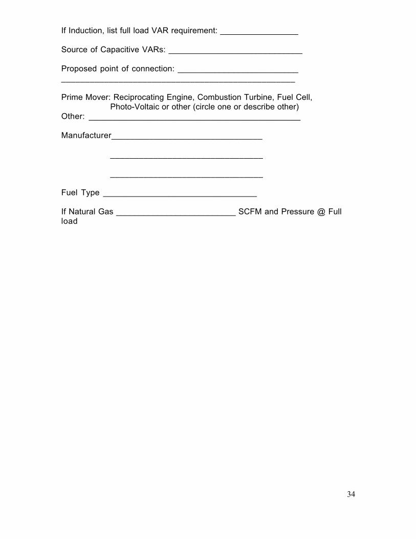
If Induction, list full load VAR requirement: _________________
Source of Capacitive VARs: _____________________________
Proposed point of connection: ___________________________________________________________________________
Prime Mover: Reciprocating Engine, Combustion Turbine, Fuel Cell,Photo-Voltaic or other (circle one or describe other)
Other: _____________________________________________
Manufacturer________________________________
________________________________
________________________________
Fuel Type _________________________________
If Natural Gas __________________________ SCFM and Pressure @ Fullload

35
Appendix D
Example of Safety Disconnect Tag
The Tag should be either glued with Siliconeadhesive or mechanically attached. Size of theTag should be as large as practical to fit on ornear the disconnect. In any case it should not beless than 4 inches by 6 inches. The Tag shall bemade of yellow laminated engraving stock withat least _ inch high black letters.
Customer Owned ParallelGeneration
PSE&G Safety DisconnectSwitch

36
If the disconnect switch is not located at themeter, than another Tag must be made that will
Appendix D – Continued.
be placed at the meter and direct PSE&Gpersonnel to the Disconnect location. Thefollowing tag shall be placed at the meter, on themeter pan or on the CT cabinet.
Customer Owned ParallelGeneration
Safety Disconnect Switchis located at rear of building
If the Disconnect Switch is located at the side ofthe building it should say so. It should bespecific enough so that PSE&G personnel caneasily find the disconnect.

APPENDIX BN.J. INTERCONNECTION APPLICATION FOR NET METERING SYSTEMS 100 kW OR SMALLER
A. Applicant InformationName: ________________________________________________________________________
Mailing Address:_________________________________________________________________
City: ______________________________________State: _______ Zip Code:_______________
Street Address (if different from above): __________________________________________
City: ____________________________________________ State: _______ Zip Code: ________
Daytime Phone: __________________ Fax: __________________ Email:__________________
Electric Utility Name: ____________________________________________________________
Electric Account No. (from utility Bill): _______________________________________________
Electric Energy Third Party Supplier_____________________________________________
Electric Energy Third Party Supplier Account No.: ________________________________________
B. System InformationManufacturer Name Plate AC Power Rating: _______ kW I
System Type: Solar Wind System Location: ______________________________
Inverter Manufacturer :___________________________________________________________________
Inverter Model No: _________________________ Inverter Serial No:
_______________________________
Inverter Location: Indoor Outdoor Self Contained Location: ___________________________
Outdoor Manual AC Disconnect Switch -
Location:_______________________________________________
C. Installation Contractor Information/Hardware and Installation ComplianceInstallation Contractor (Company Name) ______________________________________________________Contractor's License No.: _________________________ Proposed Installation Date: ____________Mailing Address: ________________________________________________________________________City: __________________________________________ State: _________ Zip Code: ________________Daytime Phone: __________________ Fax: __________________Email: ___________________________
If PV, the proposed System hardware is in compliance with Underwriters Laboratories (UL) 1741, Standardfor Static Inverters and Charge Controllers for Use in Photovoltaic Systems; UL 1703, Standard for Safety:Flat-Plate Photovoltaic Modules and Panels; and IEEE 1262-1995, IEEE Recommended Practice forQualification of Photovoltaic (PV) Modules.If PV, System must be installed in compliance with IEEE Standard 929-2000, Recommended Practice forUtility Interface of Photovoltaic Systems. All System types must be installed in compliance with applicablerequirements of local electrical codes, the Electric Utility and the National Electrical Code® (NEC) and mustuse a non-islanding inverter as defined under IEEE Standard 929-2000 (section 3.2 to 3.4).The System must have a lockable, visible disconnect device, accessible at all times to Electric DistributionCompany personnel.If the System is designed to provide uninterruptible power to critical loads, either through energy storage,back-up generator, or the generation source, the System will include a parallel blocking scheme for thisbackup source. This function may be integral to the inverter manufacturer’s packaged system.
Signed (Contractor): _________________________________________________Date: _________Name (Print): _______________________________________________

NJINTERCONNECTION APPLICATION FOR NET METERING SYSTEMS 100 kW OR SMALLER(Continued)
D. Additional Terms and Conditionsa) Operation/DisconnectionIf it appears to the Electric Distribution Company, at any time, in the reasonable exercise of its judgment, thatoperation of the System is adversely affecting or may adversely affect the Electric Distribution Company’selectrical system, the Electric Distribution Company may immediately take any and all steps it reasonablybelieves necessary to mitigate or cure the conditions including, without limitation, disconnecting the Systemfrom the Electric Distribution Company’s electrical system. Applicant/Owner shall at all times permit ElectricDistribution Company employees and inspectors reasonable access to inspect, test, or examine the Systemor metering equipment after notice by the Electric Distribution Company. Applicant/Owner may be liable forthe costs and expenses incurred by the Electric Distribution Company related to disconnection andreconnection of the System by the Electric Distribution Company when disconnection is permitted under thisparagraph D.
b) Liability/IndemnityApplicant/Owner hereby covenants and agrees to assume all risk of and liability for personal injuries(including death) and damage to property arising out of or caused by the operation of the System.Applicant/owner hereby covenants and agrees to indemnify, protect, defend and save harmless the ElectricDistribution Company, its affiliates, officers, directors, employees and agents from and against any and allclaims and demands for damages to property and injury or death to persons which may arise out of, or berelated to, or caused by, the operation of the System or its interconnection to the Electric DistributionCompany’s electrical system, except if caused solely by the gross negligence or willful misconduct of theElectric Distribution Company as determined by a court of law.
E. Electrical Code InspectionThe System referenced above satisfies applicable electrical code requirements.Inspector Name (Print): __________________________________________________________________Signed (Inspector): ____________________________________________________________________ (In lieu of the signature of the Inspector, a copy of the final Inspection Certificate may beattached)Date: ________________________ Municipality: ______________________________________________
G. Owner AcknowledgmentThe System has been installed to my satisfaction and I have been given System warranty information, andan operation manual. Also, I have been informed as to whether my PV or Wind System is eligible for netmetering, and been provided with a copy of the applicable Electric Distribution Company’s net metering tariffand interconnection requirements. I have also been instructed in the operation of the System by themanufacturer and/or the installer of the System.
I agree to abide by the terms of this Application /Agreement and I agree to operate and maintain the Systemin accordance with manufacturer’s recommended practices as well as the Electric Distribution Company’sinterconnection standards. Further, I agree to notify the Electric Distribution Company 30 days prior tomodification or replacement of the System’s components or design. Any such modification or replacementmay require submission of a new Application to the Electric Distribution Company.
I agree not to operate the System in parallel with the Electric Distribution Company until thisApplication/Agreement is accepted by the Electric Distribution Company.
I also agree to install a warning label provided by the Electric Distribution Company on or near my servicemeter location.
Signed (Owner): ___________________________________________Date: ____________________________
H. Utility Application AcceptanceThe Electric Distribution Company does not, by acceptance of this Application/Agreement, assume anyresponsibility or liability for damage to property or physical injury to persons. Further, thisApplication/Agreement does not constitute a dedication of the owner's System to the Electric DistributionCompany’s electrical system equipment or facilities.
This Application is accepted by the Electric Distribution Company on this _________ day of_________________, 200_Electric Distribution Company Representative Name (Print): ________________________________________Signed (Electric Distribution Company Representative): ___________________________________________Date: ____________________________

Please send completed applications to:
Public Service Electric & Gas Company c/o Customer Order Fulfillment 24 Brown Avenue Springfield, NJ 07081


![ELECTRIC & GAS DRYER SERVICE MANUALdiagramas.diagramasde.com/otros/Secadora LG DLG2522... [For Canada] ELECTRIC & GAS DRYER SERVICE MANUAL CAUTION READ THIS MANUAL CAREFULLY TO DIAGNOSE](https://img.pdfslide.net/doc/110x75/5bf444c109d3f21b2a8ce921/electric-gas-dryer-service-lg-dlg2522-for-canada-electric-gas-dryer-service.jpg)