Embed Size (px)
Citation preview
K-Net Doc: 5459495 UNCONTROLLED COPY WHEN PRINTED Revision No.: 0 Issue Date: April 2011 Doc. Owner: Principal Engineer Rail Systems Coordination Page 1 of 34
PUBLIC TRANSPORT SERVICES
VOLUME 2 TRAIN – TRACK AND CIVIL – STD955A – STRUCTURAL CLEARANCES – DESIGN AND RATING
PTS-MS-10-TR-STD-00000047
A and THINK

Public Transport Services Engineering Management System Volume 2 Train – Track and Civil – STD955A – Structural Clearances – Design and Rating PTS-MS-10-TR-STD-00000047
K-Net Doc: 5459495 UNCONTROLLED COPY WHEN PRINTED Revision No.: 0 Issue Date: April 2011 Doc. Owner: Principal Engineer Rail Systems Coordination Page 2 of 34
Document Control
DOCUMENT AMENDMENT RECORD Rev Change Description Date Prepared Reviewed Authorised
0 Initial Issue April 2011 Sam Sanfilippo Doug Gillott Rob Taverner

Public Transport Services Engineering Management System Volume 2 Train – Track and Civil – STD955A – Structural Clearances – Design and Rating PTS-MS-10-TR-STD-00000047
K-Net Doc: 5459495 UNCONTROLLED COPY WHEN PRINTED Revision No.: 0 Issue Date: April 2011 Doc. Owner: Principal Engineer Rail Systems Coordination Page 3 of 34
Contents
1.0 INTRODUCTION AND CONTEXT................................................................ 6
1.1 INTRODUCTION .................................................................................................... 6
1.2 PURPOSE ............................................................................................................. 6
1.3 SCOPE .................................................................................................................. 6
1.4 EXCLUSIONS ........................................................................................................ 7
1.5 REFERENCES....................................................................................................... 7
1.5.1 AUSTRALIAN STANDARDS ................................................................................. 7
1.5.2 RISSB STANDARDS ............................................................................................. 7
1.5.3 OTHER STANDARDS ........................................................................................... 8
1.5.4 PTS DOCUMENTS ............................................................................................... 8
1.5.5 PTS DRAWINGS ................................................................................................... 8
1.6 ABBREVIATIONS .................................................................................................. 9
1.7 DEFINITIONS ...................................................................................................... 10
1.8 DOCUMENT OWNER .......................................................................................... 10
2.0 FUNCTIONAL REQUIREMENTS ............................................................... 11
2.1 GENERAL ............................................................................................................ 11
2.2 CLEARANCE OUTLINES / STANDARDS ............................................................ 11
2.3 ADDITIONAL CLEARANCES ............................................................................... 13
2.4 TRAIN / INFRASTRUCTURE CLEARANCE COORDINATION ............................ 14
3.0 APPROVED CONFIGURATIONS .............................................................. 15
3.1 GENERAL ............................................................................................................ 15
3.1.1 AIM ..................................................................................................................... 15
3.1.2 OVERVIEW OF PROCEDURE ............................................................................ 15
3.2 CLASSIFICATION PROCESS ............................................................................. 17
3.2.1 STRUCTURES AND ALLOWABLE INFRINGEMENTS ........................................ 17

Public Transport Services Engineering Management System Volume 2 Train – Track and Civil – STD955A – Structural Clearances – Design and Rating PTS-MS-10-TR-STD-00000047
K-Net Doc: 5459495 UNCONTROLLED COPY WHEN PRINTED Revision No.: 0 Issue Date: April 2011 Doc. Owner: Principal Engineer Rail Systems Coordination Page 4 of 34
3.2.2 PLATFORMS ...................................................................................................... 18
3.2.3 ROLLING STOCK ............................................................................................... 19
3.2.4 TRACKS ............................................................................................................. 20
4.0 DESIGN REQUIREMENTS FOR NON-STANDARD INFRASTRUCTURE 21
4.1 GENERAL ............................................................................................................ 21
4.2 NON-STANDARD INFRASTRUCTURE CLEARANCE OUTLINES ...................... 21
4.3 EXCEPTIONAL CIRCUMSTANCES .................................................................... 21
5.0 ASSESSMENTS ......................................................................................... 22
5.1 GENERAL ............................................................................................................ 22
5.2 INFRINGEMENT .................................................................................................. 22
6.0 APPROVALS ............................................................................................. 23
6.1 GENERAL EXCEEDANCES AND INFRINGEMENTS.......................................... 23
6.2 NEW STRUCTURES OR NEW ROLLING STOCK .............................................. 23
6.3 EXISTING STRUCTURES AND EXISTING ROLLING STOCK ............................ 23
6.4 ROLLING STOCK AND STRUCTURE OUTLINE STANDARDS .......................... 24
6.5 CLEARANCE PERMITS ...................................................................................... 25
7.0 ACTIONS .................................................................................................... 26
7.1 GENERAL ............................................................................................................ 26
7.2 STATIC ROLLING STOCK OUTLINE .................................................................. 26
7.3 MAXIMUM KINEMATIC ROLLING STOCK OUTLINE.......................................... 26
7.4 STRUCTURE OUTLINE ....................................................................................... 26
7.5 BASE OPERATING STANDARD ......................................................................... 27
7.5.1 General ............................................................................................................... 27
7.5.2 Infringement of the base operating standard ........................................................ 27
7.5.3 Permanent infringement of the base operating standard (Part 1) .......................... 27
7.5.4 Permanent infringement of the base operating standard (Part 2) .......................... 28
7.6 MAINTENANCE INTERVENTION STANDARD ................................................... 28

Public Transport Services Engineering Management System Volume 2 Train – Track and Civil – STD955A – Structural Clearances – Design and Rating PTS-MS-10-TR-STD-00000047
K-Net Doc: 5459495 UNCONTROLLED COPY WHEN PRINTED Revision No.: 0 Issue Date: April 2011 Doc. Owner: Principal Engineer Rail Systems Coordination Page 5 of 34
7.6.1 General ............................................................................................................... 28
7.6.2 Infringement of the maintenance intervention standard ........................................ 28
7.7 INFRINGEMENTS ............................................................................................... 28
8.0 DOCUMENTATION .................................................................................... 29
8.1 GENERAL ............................................................................................................ 29
8.2 DOCUMENTATION OF INFRINGEMENTS ......................................................... 29
9.0 APPENDIX A – TOLERANCES AND LIMITS ............................................ 30
10.0 APPENDIX B – CLEARANCE STANDARDS DESIGN PROCEDURES ... 32
10.1 B 1: STATIC ROLLING STOCK OUTLINE ........................................................... 32
10.2 B 2: VEHICLE SWEPT PATH .............................................................................. 32
10.3 B 3: TRACK TOLERANCES................................................................................. 32
10.4 B 4: DYNAMIC ROLLING STOCK LIMITS ........................................................... 33
10.5 B 5: MAXIMUM KINEMATIC ROLLING STOCK OUTLINE .................................. 33
10.6 B 6: AIR GAP PROVISION .................................................................................. 34
10.7 B 7: BASE OPERATING STANDARD .................................................................. 34
10.8 B 8: MAINTENANCE INTERVENTION STANDARD ............................................ 34
10.9 B 8: STRUCTURE OUTLINE ............................................................................... 34
Public Transport Services Engineering Management System Volume 2 Train – Track and Civil – STD955A – Structural Clearances – Design and Rating PTS-MS-10-TR-STD-00000047
K-Net Doc: 5459495 UNCONTROLLED COPY WHEN PRINTED Revision No.: 0 Issue Date: April 2011 Doc. Owner: Principal Engineer Rail Systems Coordination Page 6 of 34
1.0 INTRODUCTION AND CONTEXT
1.1 INTRODUCTION
This document establishes the requirements for the design and rating of structural clearances associated with:
a) Broad gauge train rail assets; and
b) Other rail vehicle rail assets;
on the Adelaide Metropolitan Passenger Rail Network (AMPRN) system operated by Public Transport Services & Strategic Projects Division (PTS) and owned by the Minister for Transport.
This document shall be read in conjunction with the introductory document of the PTS Engineering Management System (EMS) identified as PTS – MS – 07 – EG – PRT – 00000046, Volume 1 Rail Asset Management – General – PRT953 – General Requirements for Rail Asset Management – Full Life Cycle.
This document supersedes the former TransAdelaide Code of Practice Volume 2 Train System Part 5 Structural Clearances, document number CP-TS-955.
This document also supersedes the DTEI Master Specification Part 1020.
1.2 PURPOSE
The purpose of this standard is to:
a) Describe the requirements in design and rating for clearances between:
i. rolling stock and fixed trackside infrastructure; and
ii. rolling stock on adjacent tracks;
b) Provide a uniform basis for compliance with the key references identified in PTS – MS – 07 – EG – PRT – 00000046, Volume 1 Rail Asset Management – General – PRT953 – General Requirements for Rail Asset Management – Full Life Cycle Clause 1.2;
c) Provide a uniform basis for compliance with PTS – MS – 07 – EG – PRT – 00000046, Volume 1 Rail Asset Management – General – PRT953 – General Requirements for Rail Asset Management – Full Life Cycle;
d) Describe the method for determining whether there is adequate clearance between rail assets including rolling stock/rail vehicles, structures and platforms;
e) Describe the actions required if the prescribed structural clearances between rail assets are compromised which include:
i. imposing appropriate restrictions on rolling stock movements to maintain safety; and/or
ii. taking action to ensure affected track or structures are restored to a safe standard.
1.3 SCOPE
This standard:
a) Applies to freight and passenger rolling stock/rail vehicles on the AMPRN;
b) Is addressed to managers, contract managers, site workers, supervisors, inspectors and designers who are responsible for ensuring safe structural clearances between rail assets;
c) Applies to existing, upgraded and new rail assets on main line tracks and crossing loops;
Public Transport Services Engineering Management System Volume 2 Train – Track and Civil – STD955A – Structural Clearances – Design and Rating PTS-MS-10-TR-STD-00000047
K-Net Doc: 5459495 UNCONTROLLED COPY WHEN PRINTED Revision No.: 0 Issue Date: April 2011 Doc. Owner: Principal Engineer Rail Systems Coordination Page 7 of 34
d) Prescribes the minimum standards; and
e) Describes the effects of rolling stock limits and track tolerances on structural clearances, including body roll, bounce and rail wear.
1.4 EXCLUSIONS
This document does not address structural clearance requirements:
a) Between rolling stock and electrically energised overhead traction equipment;
b) For light rail (trams); this is the scope of another PTS standard <Note: yet to be developed>;
c) In rail yards;
d) For double stacked container trains. A request to operate these trains on the AMPRN shall be approved by PTS;
e) For the aerodynamic effects of rail vehicles operating through a tunnel. These effects shall be considered separately in the design process; and
f) Between rolling stock and vegetation.
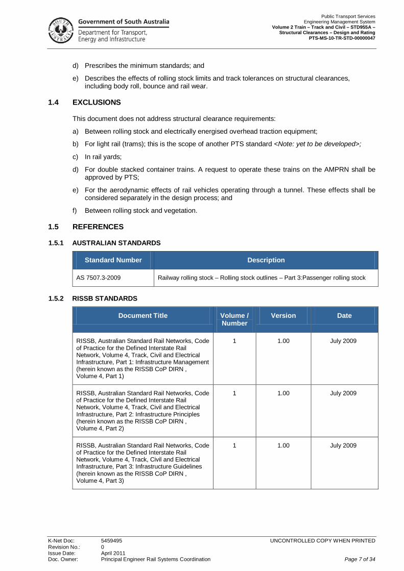
1.5 REFERENCES
1.5.1 AUSTRALIAN STANDARDS
Standard Number Description
AS 7507.3-2009 Railway rolling stock – Rolling stock outlines – Part 3:Passenger rolling stock
1.5.2 RISSB STANDARDS
Document Title Volume / Number
Version Date
RISSB, Australian Standard Rail Networks, Code of Practice for the Defined Interstate Rail Network, Volume 4, Track, Civil and Electrical Infrastructure, Part 1: Infrastructure Management (herein known as the RISSB CoP DIRN , Volume 4, Part 1)
1 1.00 July 2009
RISSB, Australian Standard Rail Networks, Code of Practice for the Defined Interstate Rail Network, Volume 4, Track, Civil and Electrical Infrastructure, Part 2: Infrastructure Principles (herein known as the RISSB CoP DIRN , Volume 4, Part 2)
1 1.00 July 2009
RISSB, Australian Standard Rail Networks, Code of Practice for the Defined Interstate Rail Network, Volume 4, Track, Civil and Electrical Infrastructure, Part 3: Infrastructure Guidelines (herein known as the RISSB CoP DIRN , Volume 4, Part 3)
1 1.00 July 2009
Public Transport Services Engineering Management System Volume 2 Train – Track and Civil – STD955A – Structural Clearances – Design and Rating PTS-MS-10-TR-STD-00000047
K-Net Doc: 5459495 UNCONTROLLED COPY WHEN PRINTED Revision No.: 0 Issue Date: April 2011 Doc. Owner: Principal Engineer Rail Systems Coordination Page 8 of 34
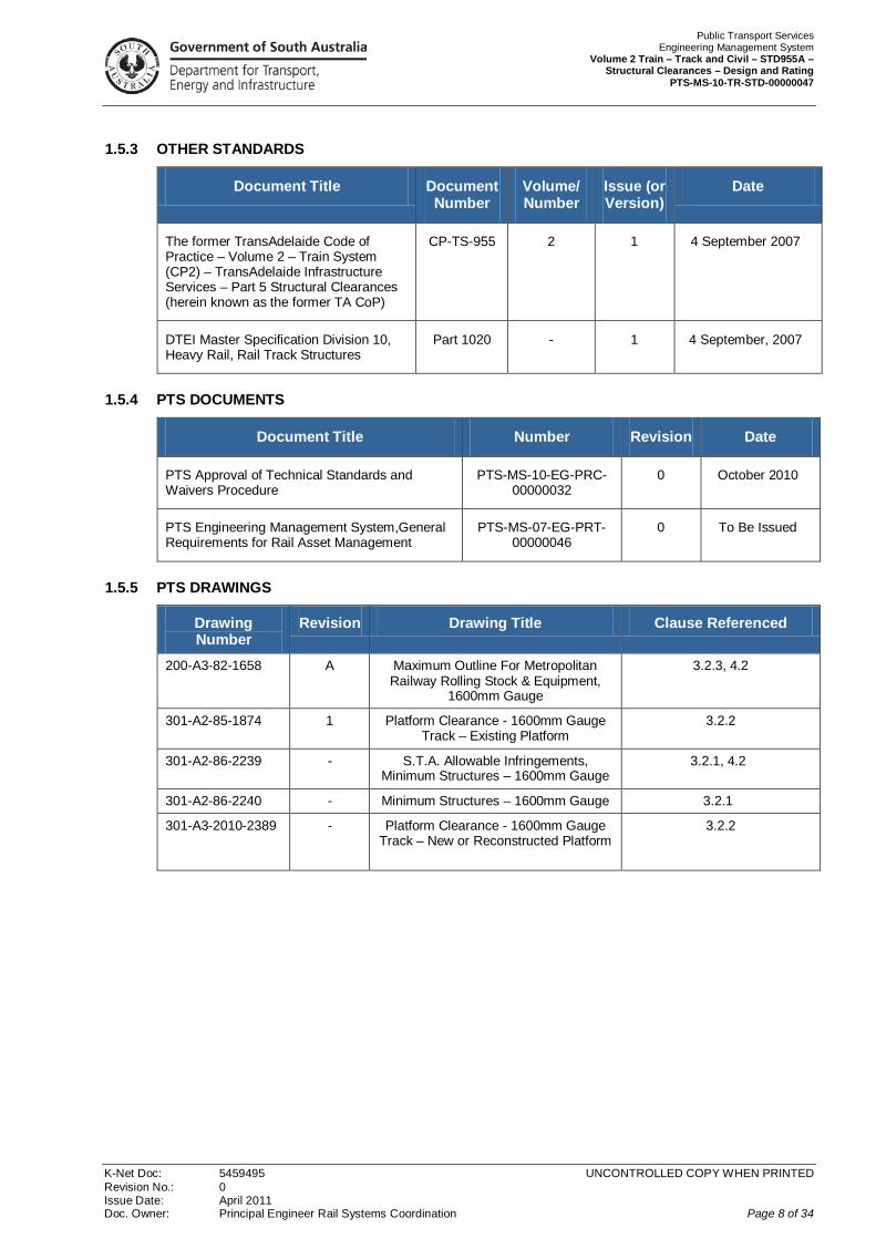
1.5.3 OTHER STANDARDS
Document Title Document Number
Volume/ Number
Issue (or Version)
Date
The former TransAdelaide Code of Practice – Volume 2 – Train System (CP2) – TransAdelaide Infrastructure Services – Part 5 Structural Clearances (herein known as the former TA CoP)
CP-TS-955 2 1 4 September 2007
DTEI Master Specification Division 10, Heavy Rail, Rail Track Structures
Part 1020 - 1 4 September, 2007
1.5.4 PTS DOCUMENTS
Document Title Number Revision Date
PTS Approval of Technical Standards and Waivers Procedure
PTS-MS-10-EG-PRC-00000032
0 October 2010
PTS Engineering Management System,General Requirements for Rail Asset Management
PTS-MS-07-EG-PRT-00000046
0 To Be Issued
1.5.5 PTS DRAWINGS
Drawing Number
Revision Drawing Title Clause Referenced
200-A3-82-1658 A Maximum Outline For Metropolitan Railway Rolling Stock & Equipment,
1600mm Gauge
3.2.3, 4.2
301-A2-85-1874 1 Platform Clearance - 1600mm Gauge Track – Existing Platform
3.2.2
301-A2-86-2239 - S.T.A. Allowable Infringements, Minimum Structures – 1600mm Gauge
3.2.1, 4.2
301-A2-86-2240 - Minimum Structures – 1600mm Gauge 3.2.1
301-A3-2010-2389 - Platform Clearance - 1600mm Gauge Track – New or Reconstructed Platform
3.2.2

Public Transport Services Engineering Management System Volume 2 Train – Track and Civil – STD955A – Structural Clearances – Design and Rating PTS-MS-10-TR-STD-00000047
K-Net Doc: 5459495 UNCONTROLLED COPY WHEN PRINTED Revision No.: 0 Issue Date: April 2011 Doc. Owner: Principal Engineer Rail Systems Coordination Page 9 of 34
1.6 ABBREVIATIONS
Abbreviation Meaning
AMPRN Adelaide Metropolitan Passenger Rail Network
CoP DIRN Code of Practice for the Defined Interstate Rail Network
CP-TS Code of Practice, Technical Standard
DTEI Department for Transport, Energy and Infrastructure
PTS Public Transport Services & Strategic Projects Division
PTS EMS Public Transport Services & Strategic Projects Division Engineering Management System
RISSB Rail Industry Safety and Standards Board
RISSB CoP DIRN Rail Industry Safety and Standards Board Code of Practice for the Defined Interstate Rail Network
TA CoP The former TransAdelaide Code of Practice
Public Transport Services Engineering Management System Volume 2 Train – Track and Civil – STD955A – Structural Clearances – Design and Rating PTS-MS-10-TR-STD-00000047
K-Net Doc: 5459495 UNCONTROLLED COPY WHEN PRINTED Revision No.: 0 Issue Date: April 2011 Doc. Owner: Principal Engineer Rail Systems Coordination Page 10 of 34
1.7 DEFINITIONS
For definitions refer to document XXXX PTS EMS Glossary. < Note; this document is yet to be developed>
1.8 DOCUMENT OWNER
The ownership and responsibility for maintenance of this document lies with the Director Asset Management.
The approval for the contents of this document shall be in accordance with the process described in the PTS document Approval of Technical Standards and Waivers Procedure.
Public Transport Services Engineering Management System Volume 2 Train – Track and Civil – STD955A – Structural Clearances – Design and Rating PTS-MS-10-TR-STD-00000047
K-Net Doc: 5459495 UNCONTROLLED COPY WHEN PRINTED Revision No.: 0 Issue Date: April 2011 Doc. Owner: Principal Engineer Rail Systems Coordination Page 11 of 34
2.0 FUNCTIONAL REQUIREMENTS
2.1 GENERAL
The processes described in this document shall be:
a) Used to determine clearance requirements for the following infrastructure:
i. Structures and Allowable Infringements, including overpass bridges and associated columns/walls, level crossing mechanisms, pedestrian crossing fences and maze ways, turnouts and associated appurtenances, dwarf switchstands and goods platforms;
ii. Station Platforms;
iii. Rolling stock, which includes trains and other rail vehicles; and
iv. Tracks, including any two tracks adjacent to one another; and
b) Read in conjunction with the requirements of the PTS EMS introductory document referenced in Clause 1.1.
2.2 CLEARANCE OUTLINES / STANDARDS
Clearance outlines / standards for the above mentioned infrastructure shall be determined and specified for all line sections and operators (either PTS or a third party).
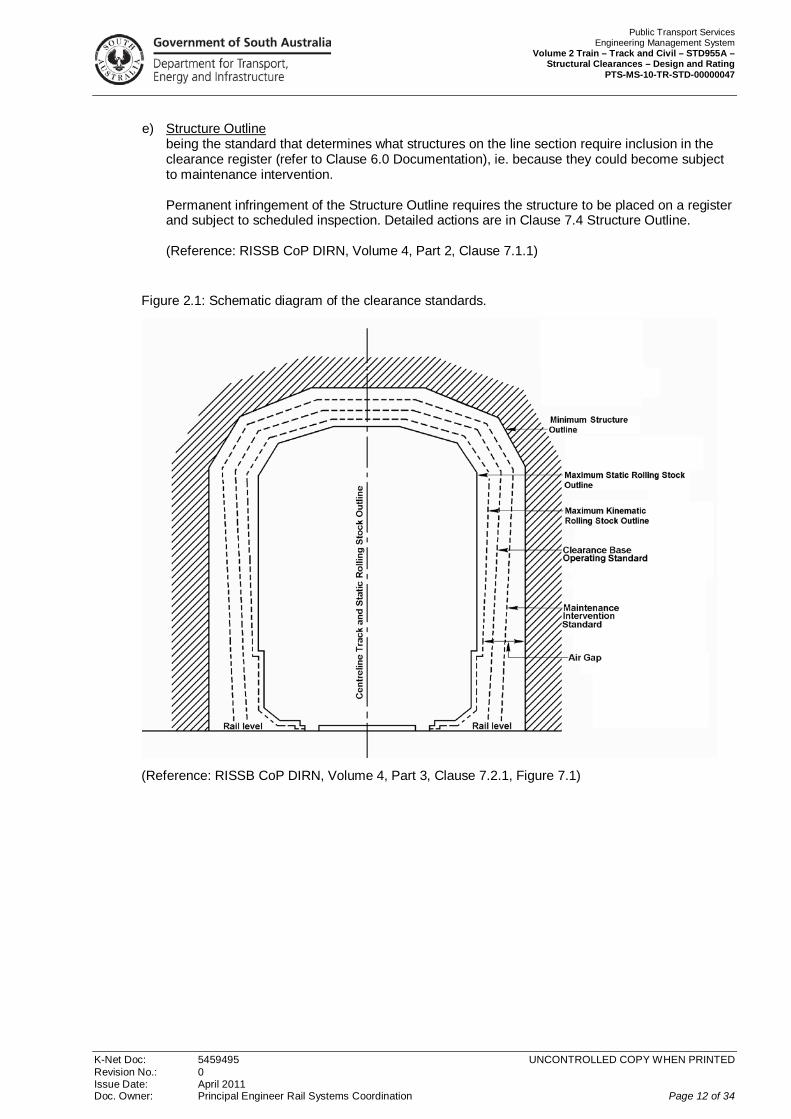
Clearance outlines/standards are illustrated in Figure 2.1 and described as follows:
a) Static Rolling Stock Outline being the cross-sectional outline of a maximum size vehicle at rest. Detailed actions are provided in Clause 7.2 Static Rolling Stock Outline;
b) Maximum Kinematic Rolling Stock Outline being equivalent to the “permissible rolling stock outline” defined in AS 4292.2 and includes the effects of vehicle centre and end throw, track tolerances and dynamic rolling stock limits provided in Appendix A. Infringement of the Maximum Kinematic Rolling Stock Outline shall not be permitted in normal operations and shall be treated as a track obstruction. Detailed actions are provided in Clause 7.3 Maximum Kinematic Rolling Stock Outline;
c) Base Operating Standard being the outline which may be infringed only in special circumstances and subject to there being no exceedance of the appropriate track tolerances for clearance. Infringement of the Base Operating Standard requires immediate action to be taken prior to the next train. Detailed actions are provided in Clause 7.5 Base Operating Standard;
d) Maintenance Intervention Standard being the outline that will require maintenance actions to be taken to restore clearances to a standard such that no operating restrictions are required. Infringement of the Maintenance Intervention Standard requires action to be taken to restore clearances together with increased monitoring and inspection. Detailed actions are provided in Clause 7.6 Maintenance Intervention Standard; and
Public Transport Services Engineering Management System Volume 2 Train – Track and Civil – STD955A – Structural Clearances – Design and Rating PTS-MS-10-TR-STD-00000047
K-Net Doc: 5459495 UNCONTROLLED COPY WHEN PRINTED Revision No.: 0 Issue Date: April 2011 Doc. Owner: Principal Engineer Rail Systems Coordination Page 12 of 34
e) Structure Outline being the standard that determines what structures on the line section require inclusion in the clearance register (refer to Clause 6.0 Documentation), ie. because they could become subject to maintenance intervention. Permanent infringement of the Structure Outline requires the structure to be placed on a register and subject to scheduled inspection. Detailed actions are in Clause 7.4 Structure Outline. (Reference: RISSB CoP DIRN, Volume 4, Part 2, Clause 7.1.1)
Figure 2.1: Schematic diagram of the clearance standards.
(Reference: RISSB CoP DIRN, Volume 4, Part 3, Clause 7.2.1, Figure 7.1)
Public Transport Services Engineering Management System Volume 2 Train – Track and Civil – STD955A – Structural Clearances – Design and Rating PTS-MS-10-TR-STD-00000047
K-Net Doc: 5459495 UNCONTROLLED COPY WHEN PRINTED Revision No.: 0 Issue Date: April 2011 Doc. Owner: Principal Engineer Rail Systems Coordination Page 13 of 34
2.3 ADDITIONAL CLEARANCES
In addition to the clearance outlines / standards detailed in Clause 2.2, where required by PTS, provision shall be made for:
a) Access or egress (emergency or otherwise);
b) Rolling stock clearances to people, plant or equipment;
c) Projection of parts of the human body from rolling stock;
d) Risks from derailed rolling stock;
e) Other health and safety reasons;
f) Services requirements;
g) Access for rail maintenance;
h) Future clearance upgrades (see Note below);
i) Tunnels;
j) Work or tourist train profiles; and
k) Future conversion to standard gauge on the AMPRN.
Where a guard rail has been fitted to provide protection to a structure in the event of a derailment, the structure outline shall be widened to accommodate derailed rolling stock running against the guard rail.
Note: For further information about the above additional clearances, refer to the CoP DIRN a) Volume 5: Rolling Stock and b) the Interface Coordination Plan described in Volume 1: General Requirements and Interface Management.
(References:
a) RISSB CoP DIRN, Volume 4 Part 2 Clause 7.1.2 and Part 3 Clause 7.1; and
b) Former TA CoP Part 5 Clause 2.2).
Public Transport Services Engineering Management System Volume 2 Train – Track and Civil – STD955A – Structural Clearances – Design and Rating PTS-MS-10-TR-STD-00000047
K-Net Doc: 5459495 UNCONTROLLED COPY WHEN PRINTED Revision No.: 0 Issue Date: April 2011 Doc. Owner: Principal Engineer Rail Systems Coordination Page 14 of 34
2.4 TRAIN / INFRASTRUCTURE CLEARANCE COORDINATION
The interface coordination plan (refer to the PTS EMS introductory document referenced in Clause 1.1) shall provide for the certification of:
a) Trains, rolling stock and their loadings; and
b) Infrastructure;
to ensure that the specified clearance standards are maintained.
The factors to be considered in determining these standards include the following:
a) Rolling stock dimensions including loading and kinematic effects;
b) Location and dimension of fixed or moveable structures and equipment (including track mounted equipment);
c) Vegetation encroachment;
d) Rolling stock movement and dynamic response;
e) Static and passing clearances to electrical and other lineside equipment;
f) Track alignment (including curvature) and tolerances;
g) Rolling stock, track and electrical equipment maintenance standards that may influence clearances including:
i. wheel flange to rail clearance and wear;
ii. track gauge and superelevation and their tolerances;
h) Air Gap provided between rolling stock and structures, equipment, signs or other rolling stock;
i) Additional clearance for access and egress (emergency or otherwise) as identified in Clause 2.3; and
j) Other identified risks that may result in obstruction of the track.
Certification of trains, rolling stock and their loadings may be achieved in the interface coordination plan through an operator’s commitment to conform with specific design, commissioning, maintenance and loading practices consistent with the principles outlined in this Section.
Certification of the infrastructure may be achieved through the commitment of PTS in the interface coordination plan to conform with specific design, commissioning, and maintenance practices consistent with the principles outlined in this Section.
(Reference: RISSB CoP DIRN, Volume 4, Part 2, Clause 7.1.2)

Public Transport Services Engineering Management System Volume 2 Train – Track and Civil – STD955A – Structural Clearances – Design and Rating PTS-MS-10-TR-STD-00000047
K-Net Doc: 5459495 UNCONTROLLED COPY WHEN PRINTED Revision No.: 0 Issue Date: April 2011 Doc. Owner: Principal Engineer Rail Systems Coordination Page 15 of 34
3.0 APPROVED CONFIGURATIONS
3.1 GENERAL
3.1.1 AIM
Design is the process used to determine that any proposed new infrastructure will be able to meet the design functional parameters. For structural clearances the requirement is to confirm that the proposed new infrastructure configuration (structure outline, platforms and allowable infringements, static rolling stock outline and track centres) will be suitable for the proposed functional parameters (including vehicle speed, vehicle axle loading, vehicle type and allowable structural clearances). That is, confirming that the new infrastructure will have an approved configuration.
Rating is the process used to determine whether the existing functional parameters are permissible for the existing infrastructure. For structural clearances the requirement is to confirm that the existing functional parameters (including vehicle speed, vehicle axle loading, vehicle type and actual structural clearances) are permissible for the existing infrastructure configuration (structure outline, platforms and allowable infringements, static rolling stock outline and existing track centres). That is, confirming that the existing infrastructure has an approved configuration.
The aim of design and rating for structural clearances is to provide authorisation for the use of infrastructure with approved configuration.
This Section describes the procedure to be adopted to determine whether the infrastructure has an approved configuration or not.
3.1.2 OVERVIEW OF PROCEDURE
Full details of the determination procedure are provided in Clause 3.2, and an overview of the procedure is as follows:
Step 1) Determine the infrastructure’s classification as either;
a) Standard Infrastructure; or
b) Non-Standard Infrastructure;
Step 2) If the determination shows the infrastructure is:
a) Standard Infrastructure, then it is considered suitable for use on the AMPRN; or
b) Non-Standard Infrastructure, then actions are required in accordance with:
i. Clause 3.2; and
ii. Clause 4.0 which determines whether the Non-Standard Infrastructure has approved configuration.
This procedure is shown diagrammatically in Figure 3.1.

Public Transport Services Engineering Management System Volume 2 Train – Track and Civil – STD955A – Structural Clearances – Design and Rating PTS-MS-10-TR-STD-00000047
K-Net Doc: 5459495 UNCONTROLLED COPY WHEN PRINTED Revision No.: 0 Issue Date: April 2011 Doc. Owner: Principal Engineer Rail Systems Coordination Page 16 of 34
Figure 3.1: Flowchart of determination procedure.
Determine Classification(Clause 3.2)
Determine Clearance Outlines
(Clause 4.2, Step 1)
Conduct Configuration
Test (Clause 4.2,
Step 3)
Determination:Non-Standard Infrastructure has approved configuration (Clause 4.2,
Step 4)
Infrastructure suitable for use
on AMPRN
Infrastructure suitable for use
on AMPRN
Infrastructure not suitable for use
on AMPRN
1) Actions required; and
2) Refer to Clause 4.0
Standard Infrastructure with approved configuration
Non
-Sta
ndar
d In
frast
ruct
ure
Test Failed
Test Passed
Determination:Non-Standard Infrastructure
has non-approved configuration (Clause 4.2,
Step 4)
Calculate Kinematic
Outline (Clause 4.2,
Step 2)

Public Transport Services Engineering Management System Volume 2 Train – Track and Civil – STD955A – Structural Clearances – Design and Rating PTS-MS-10-TR-STD-00000047
K-Net Doc: 5459495 UNCONTROLLED COPY WHEN PRINTED Revision No.: 0 Issue Date: April 2011 Doc. Owner: Principal Engineer Rail Systems Coordination Page 17 of 34
3.2 CLASSIFICATION PROCESS
3.2.1 STRUCTURES AND ALLOWABLE INFRINGEMENTS
a) Standard Structures and Allowable Infringements are structures and allowable infringements with a Structure Outline that conforms to the following drawings (refer to Clause 1.5.5 for details of these drawings):
i. 301-A2-86-2239 (S.T.A. Allowable Infringements, Minimum Structures – 1600mm Gauge); and
ii. 301-A2-86-2240 (Minimum Structures – 1600mm Gauge).
If the configuration of the structures and allowable infringements complies with these drawings then it shall be considered Standard Infrastructure with approved configuration, and is thus deemed suitable for use on the AMPRN.
Notes:
[1] on curves additional horizontal clearance shall be provided in accordance with the tables in the standard drawings;
[2] where track is wide to gauge the centreline of the track shall be considered to be 800mm behind the gauge face of the near rail for the purposes of measuring horizontal distances to adjacent structures or parallel tracks;
[3] for measuring horizontal and vertical distances to adjacent structures or parallel tracks, on canted track, the vertical centreline of the track shall be considered to be at right angles to the plane of the running surface of the two rails; and
[4] these Notes were referenced from the former TA CoP, Part 5, Clause 3.1;
b) Non-Standard Structures and Allowable Infringements are structures and allowable infringements not meeting the requirements for Standard Structures and Allowable Infringements.
These structures and allowable infringements shall:
i. be recorded in a maintained register with the listing of all other Non-Standard Structures and Allowable Infringements, indicating the amount of deviation from the standard drawings; and
ii. be recorded on an accurate and maintained drawing for locations which infringe the horizontal clearance by more than 100mm;
iii. have more stringent track geometry standards - as shown in the document XXX Track Geometry - Design and Rating <Note: document yet to be developed; vide former TA CoP CP-TS-956 (Track Geometry)> - applied to compensate for the reduced clearances to the structure. The register indicated in sub-clause (b) (i) above shall also indicate where this more stringent track geometry standard requirement applies; and
iv. comply with the requirements of Clause 4.0 Design Requirements for Non-Standard Infrastructure.
(Reference: former TA CoP, Part 5, Clause 3.2)
Public Transport Services Engineering Management System Volume 2 Train – Track and Civil – STD955A – Structural Clearances – Design and Rating PTS-MS-10-TR-STD-00000047
K-Net Doc: 5459495 UNCONTROLLED COPY WHEN PRINTED Revision No.: 0 Issue Date: April 2011 Doc. Owner: Principal Engineer Rail Systems Coordination Page 18 of 34
3.2.2 PLATFORMS
a) Standard Platforms are platforms with a Platform Outline that conforms to the following drawings (refer to Clause 1.5.5 for details of these drawings):
i. 301-A2-85-1874 (Platform Clearance - 1600mm Gauge Track – Existing Platform); and
ii. 301-A3-2010-2389 (Platform Clearance - 1600mm Gauge Track – New or Reconstructed Platform). If the configuration of the platforms complies with these drawings then it shall be considered Standard Infrastructure with approved configuration, and is thus deemed suitable for use on the AMPRN;
b) Non-Standard Platforms are platforms not meeting the requirements for Standard Platforms. These platforms shall:
i. be recorded in a maintained register with the listing of all other Non-Standard Platforms indicating the amount of deviation from the standard drawing;
ii. be recorded on an accurate and maintained drawing for locations which infringe the horizontal clearance by more than 100mm;
iii. have more stringent track geometry standards - as shown in the document XXX Track Geometry - Design and Rating <Note: yet to be developed; vide former TA CoP CP-TS-956 (Track Geometry)> - applied to compensate for the reduced clearances to the Platform and Other Allowable Infringements. The register indicated in sub-clause (b) (i) above shall also indicate where this track geometry standard requirement applies; and
iv. comply with the requirements of Clause 4.0 Design Requirements for Non-Standard Infrastructure.
(Reference: former TA CoP, Part 5, Clause 3.2)
Public Transport Services Engineering Management System Volume 2 Train – Track and Civil – STD955A – Structural Clearances – Design and Rating PTS-MS-10-TR-STD-00000047
K-Net Doc: 5459495 UNCONTROLLED COPY WHEN PRINTED Revision No.: 0 Issue Date: April 2011 Doc. Owner: Principal Engineer Rail Systems Coordination Page 19 of 34
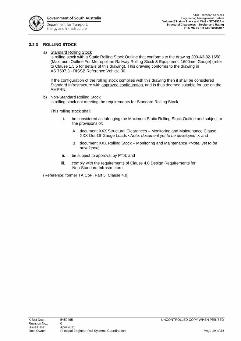
3.2.3 ROLLING STOCK
a) Standard Rolling Stock is rolling stock with a Static Rolling Stock Outline that conforms to the drawing 200-A3-82-1658 (Maximum Outline For Metropolitan Railway Rolling Stock & Equipment, 1600mm Gauge) (refer to Clause 1.5.5 for details of this drawing). This drawing conforms to the drawing in AS 7507.3 - RISSB Reference Vehicle 30. If the configuration of the rolling stock complies with this drawing then it shall be considered Standard Infrastructure with approved configuration, and is thus deemed suitable for use on the AMPRN;
b) Non-Standard Rolling Stock is rolling stock not meeting the requirements for Standard Rolling Stock. This rolling stock shall:
i. be considered as infringing the Maximum Static Rolling Stock Outline and subject to the provisions of:
A. document XXX Structural Clearances – Monitoring and Maintenance Clause XXX Out-Of-Gauge Loads <Note: document yet to be developed >; and
B. document XXX Rolling Stock – Monitoring and Maintenance <Note: yet to be developed;
ii. be subject to approval by PTS; and
iii. comply with the requirements of Clause 4.0 Design Requirements for Non-Standard Infrastructure.
(Reference: former TA CoP, Part 5, Clause 4.0)

Public Transport Services Engineering Management System Volume 2 Train – Track and Civil – STD955A – Structural Clearances – Design and Rating PTS-MS-10-TR-STD-00000047
K-Net Doc: 5459495 UNCONTROLLED COPY WHEN PRINTED Revision No.: 0 Issue Date: April 2011 Doc. Owner: Principal Engineer Rail Systems Coordination Page 20 of 34
3.2.4 TRACKS
a) Standard Tracks are straight and curved adjacent tracks on running lines and/or sidings with:
i. Alternative 1 (most preferred): minimum track centres of 4.0m, or
ii. Alternative 2 (least preferred): minimum track centres between rail tracks to give sufficient clearance between the maximum kinematic rolling stock outlines on each track that provides an “Air Gap” of not less than 300mm under the local conditions. The method used to develop this track configuration shall be in accordance with the method described in Clause 4.2. Before Alternative 2 is adopted, it shall be demonstrated (by drawings and calculations) that Alternative 1 can not be achieved. Alternative 2 requires approval from PTS. Note: in order to provide adequate clearance between rolling stock and structures, or rolling stock on adjacent tracks, design/rating and monitoring/maintenance of track position is based on the “Air Gap”, which is defined as:
A) referenced from the CoP DIRN; a gap between the maximum kinematic outline and structures, or between maximum kinematic outlines on adjacent tracks, which provides a margin for maintenance or other action to maintain clearances prior to infringement of the maximum kinematic outline; or
B) referenced from the former TA CoP, Part 5, Clause 2.4; to ensure adequate clearances between rolling stock and structures, or rolling stock on adjacent tracks, monitoring and maintenance of track position is based on the “Air Gap”, which is defined as follows:
i. at a specific location, the shortest distance between a structure and the maximum kinematic rolling stock outline;
ii. at a specific location, the shortest distance between the maximum kinematic rolling stock outlines on two adjacent tracks.
If the configuration of the tracks complies with Alternatives 1 or 2 then the infrastructure shall be considered Standard Infrastructure with approved configuration, and is thus deemed suitable for use on the AMPRN;
b) Non-Standard Tracks are tracks not meeting the requirements for Standard Tracks. These tracks shall:
i. be recorded in a maintained register with the listing of all other Non-Standard Track locations indicating the track centre dimensions;
ii. have more stringent track geometry standards - as shown in the document XXX Track Geometry - Design and Rating <Note: yet to be developed; vide former TA CoP CP-TS-956 (Track Geometry)> - applied to compensate for the reduced track centres. The register indicated in sub-clause (b) (i) above shall also indicate where this requirement applies and the limits on deterioration, with speed limits where applicable; and
iii. comply with the requirements of Clause 4.0 Design Requirements for Non-Standard Infrastructure.
(Reference: former TA CoP, Part 5, Clause 5.0)
Public Transport Services Engineering Management System Volume 2 Train – Track and Civil – STD955A – Structural Clearances – Design and Rating PTS-MS-10-TR-STD-00000047
K-Net Doc: 5459495 UNCONTROLLED COPY WHEN PRINTED Revision No.: 0 Issue Date: April 2011 Doc. Owner: Principal Engineer Rail Systems Coordination Page 21 of 34
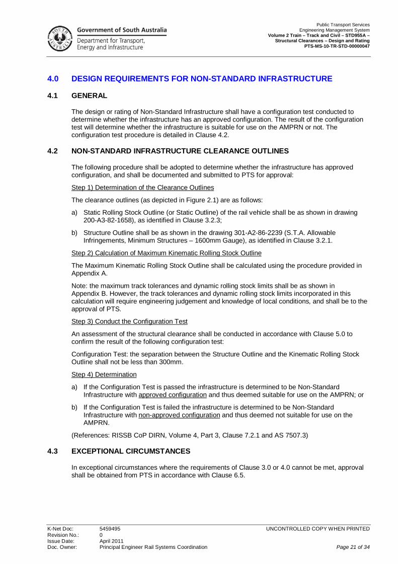
4.0 DESIGN REQUIREMENTS FOR NON-STANDARD INFRASTRUCTURE
4.1 GENERAL
The design or rating of Non-Standard Infrastructure shall have a configuration test conducted to determine whether the infrastructure has an approved configuration. The result of the configuration test will determine whether the infrastructure is suitable for use on the AMPRN or not. The configuration test procedure is detailed in Clause 4.2.
4.2 NON-STANDARD INFRASTRUCTURE CLEARANCE OUTLINES
The following procedure shall be adopted to determine whether the infrastructure has approved configuration, and shall be documented and submitted to PTS for approval:
Step 1) Determination of the Clearance Outlines
The clearance outlines (as depicted in Figure 2.1) are as follows:
a) Static Rolling Stock Outline (or Static Outline) of the rail vehicle shall be as shown in drawing 200-A3-82-1658), as identified in Clause 3.2.3;
b) Structure Outline shall be as shown in the drawing 301-A2-86-2239 (S.T.A. Allowable Infringements, Minimum Structures – 1600mm Gauge), as identified in Clause 3.2.1.
Step 2) Calculation of Maximum Kinematic Rolling Stock Outline
The Maximum Kinematic Rolling Stock Outline shall be calculated using the procedure provided in Appendix A.
Note: the maximum track tolerances and dynamic rolling stock limits shall be as shown in Appendix B. However, the track tolerances and dynamic rolling stock limits incorporated in this calculation will require engineering judgement and knowledge of local conditions, and shall be to the approval of PTS.
Step 3) Conduct the Configuration Test
An assessment of the structural clearance shall be conducted in accordance with Clause 5.0 to confirm the result of the following configuration test:
Configuration Test: the separation between the Structure Outline and the Kinematic Rolling Stock Outline shall not be less than 300mm.
Step 4) Determination
a) If the Configuration Test is passed the infrastructure is determined to be Non-Standard Infrastructure with approved configuration and thus deemed suitable for use on the AMPRN; or
b) If the Configuration Test is failed the infrastructure is determined to be Non-Standard Infrastructure with non-approved configuration and thus deemed not suitable for use on the AMPRN.
(References: RISSB CoP DIRN, Volume 4, Part 3, Clause 7.2.1 and AS 7507.3)
4.3 EXCEPTIONAL CIRCUMSTANCES
In exceptional circumstances where the requirements of Clause 3.0 or 4.0 cannot be met, approval shall be obtained from PTS in accordance with Clause 6.5.

Public Transport Services Engineering Management System Volume 2 Train – Track and Civil – STD955A – Structural Clearances – Design and Rating PTS-MS-10-TR-STD-00000047
K-Net Doc: 5459495 UNCONTROLLED COPY WHEN PRINTED Revision No.: 0 Issue Date: April 2011 Doc. Owner: Principal Engineer Rail Systems Coordination Page 22 of 34
5.0 ASSESSMENTS
5.1 GENERAL
Assessments of existing infrastructure shall be undertaken in accordance with the requirements of the PTS EMS introductory document referenced in Clause 1.1.
5.2 INFRINGEMENT
An assessment shall determine whether the structure (or the maximum kinematic rolling stock outline on adjacent tracks) causes an infringement of the:
a) Structure Outline Standard where the separation between the Maximum Kinematic Rolling Stock Outline and the Structure Outline is less than 300mm;
b) Maintenance Intervention Standard where the separation between the Maximum Kinematic Rolling Stock Outline and the Structure Outline is less than 200mm; or
c) Base Operating Standard where the separation between the Maximum Kinematic Rolling Stock Outline and the Structure Outline is less than 100mm.
(Reference: RISSB CoP DIRN, Volume 4, Part 3, Clause 7.5.2, 7.2.2 and 7.2.7)

Public Transport Services Engineering Management System Volume 2 Train – Track and Civil – STD955A – Structural Clearances – Design and Rating PTS-MS-10-TR-STD-00000047
K-Net Doc: 5459495 UNCONTROLLED COPY WHEN PRINTED Revision No.: 0 Issue Date: April 2011 Doc. Owner: Principal Engineer Rail Systems Coordination Page 23 of 34
6.0 APPROVALS
6.1 GENERAL EXCEEDANCES AND INFRINGEMENTS
Approval of the following exceedances and infringements shall be obtained in accordance with the requirements of the PTS EMS introductory document referenced in Clause 1.1.
a) Exceedance of the Static Rolling Stock Outline (refer to Clause 3.2.3), which includes out-of-gauge loads (refer to document XXX Structural Clearances - Monitoring and Maintenance <Note: yet to be developed>);
b) Exceedance of Dynamic Rolling Stock Limits or Track Tolerances (refer to Appendix A) used to determine the Maximum Kinematic Rolling Stock Outline;
c) Infringement of the Structure Outline;
d) Infringement of the Base Operating Standard; and
e) Infringement of the Maintenance Intervention Standard.
Any approval granted by PTS may be subject to conditions including speed restrictions or tightened track tolerances.
(Reference: RISSB CoP DIRN, Volume 4, Part 3, Clause 7.2.3)
6.2 NEW STRUCTURES OR NEW ROLLING STOCK
Approvals for new structures or new types of rolling stock shall be in accordance with one or other of the following:
a) The principles set out in Clause 2.0 where the dynamic rolling stock limits and track tolerances used shall be appropriate to the actual rolling stock and infrastructure combination being considered;
b) Designs recommended in Clause 6.4 where the dynamic rolling stock limits in Table 1 and track tolerances in Table 2 of Appendix A shall be appropriate to the actual rolling stock and infrastructure combination being considered; or
c) Existing clearance standards where the maximum kinematic rolling stock outline shall be appropriate to the dynamic rolling stock limits and track tolerances of the actual rolling stock and infrastructure combination being considered.
(Reference: RISSB CoP DIRN, Volume 4, Part 3, Clause 7.2.5)
6.3 EXISTING STRUCTURES AND EXISTING ROLLING STOCK
Approvals for existing structures and existing types of rolling stock shall be in accordance with the drawings identified in:
a) Clause 3.2.1; and
b) Clause 3.2.3.
(Reference: RISSB CoP DIRN, Volume 4, Part 3, Clause 7.2.6)

Public Transport Services Engineering Management System Volume 2 Train – Track and Civil – STD955A – Structural Clearances – Design and Rating PTS-MS-10-TR-STD-00000047
K-Net Doc: 5459495 UNCONTROLLED COPY WHEN PRINTED Revision No.: 0 Issue Date: April 2011 Doc. Owner: Principal Engineer Rail Systems Coordination Page 24 of 34
6.4 ROLLING STOCK AND STRUCTURE OUTLINE STANDARDS
The Structure Outline has been derived from the Static Rolling Stock Outline by applying the following:
a) Dynamic rolling stock limits from Table 1 in Appendix A;
b) Track tolerances from Table 2 in Appendix A;
c) 150mm and 0mm cant elevation to provide for clearances on the inside and outside rail respectively of curved track;
d) For curves of 300m radius or greater, centre and end throws based on 300m radius;
e) For curves of radius 100m and greater, but less than 300m radius, centre and end throws based on 100m radius; and
f) 300mm air gap (see Note).
The other clearance outlines specified in Clause 2.2 shall be determined as follows:
Table 6.1: Clearance Outlines
Clearance Standards Distance inside the adopted Structure Outline
Maintenance Intervention Standard 100mm
Base Operating Standard 200mm
Maximum Kinematic Rolling Stock Outline 300mm
Note: As a simplification, the structure outline has been extended downwards as a vertical line from the widest point on each side. Accordingly, the structure outline does not make allowance for structures such as platforms and points machines that need to be located close to the track. The requirements for such structures may be derived using the above guidelines but with suitably reduced air gaps (which shall be approved by PTS) and compatible monitoring requirements.
For the approval process, the Static Rolling Stock Outline identified in Clause 3.2.3 shall be adopted for use with Structure Outline identified in Clause 3.2.1.
(Reference: RISSB CoP DIRN, Volume 4, Part 3, Clause 7.2.7)

Public Transport Services Engineering Management System Volume 2 Train – Track and Civil – STD955A – Structural Clearances – Design and Rating PTS-MS-10-TR-STD-00000047
K-Net Doc: 5459495 UNCONTROLLED COPY WHEN PRINTED Revision No.: 0 Issue Date: April 2011 Doc. Owner: Principal Engineer Rail Systems Coordination Page 25 of 34
6.5 CLEARANCE PERMITS
In exceptional circumstances where the requirements of Clause 3.0 or 4.0 cannot be met, approval shall be evidenced by a Clearance Permit issued by PTS in accordance with the requirements of the PTS EMS introductory document referenced in Clause 1.1.
The Clearance Permit is to:
a) Provide a detailed drawing of the actual static rolling stock outline applicable – not the Static Rolling Stock Outline shown in Clause 3.2.3;
b) Provide a detailed drawing of the structure outline applicable at the site – not the Structure Outline shown in Clause 3.2.1;
c) Provide a listing of the actual dynamic rolling stock limits and track tolerances – not the Rolling Stock Limits and Track Tolerances shown in Tables 1 and 2 of Appendix A;
d) Provide calculations of the maximum kinematic rolling stock outline applicable at this location based on:
i. the actual static rolling stock outline applicable; and
ii. the worst-case combination of the site specific actual dynamic rolling stock limits and track tolerances;
iii. the procedure in Clause 4.2.
e) Demonstrate that a special or restricted circumstance applies to the specific site;
f) Contain the following information:
i. Track Name and Identification Code;
ii. Kilometre Start: kilometrage of the start location of the track section, or the kilometrage of the discrete location;
iii. Kilometre End: kilometrage of the end location of the track section;
iv. Structure Geometry: horizontal and vertical dimensions of structure from design track centreline at top-of-rail plane;
v. Track Geometry: horizontal geometry (i.e. radius, superelevation, location of frame points), track centres, vertical geometry, relative track levels;
vi. Track Structure: sleeper type, rail size;
vii. Operations Description: rolling stock outline, track speed;
viii. Duration for which the conditions will apply; and
ix. Infringement: magnitude of infringement to the Structure Outline (in mm);
g) Be accompanied with any site-specific requirements that apply which may include:
i. increased inspection or maintenance interval;
ii. tighter maintenance tolerances;
iii. limited duration of permit; and/or
iv. restricted operational speed; and
h) Be supplied in accordance with the requirements of the PTS EMS introductory document referenced in Clause 1.1.

Public Transport Services Engineering Management System Volume 2 Train – Track and Civil – STD955A – Structural Clearances – Design and Rating PTS-MS-10-TR-STD-00000047
K-Net Doc: 5459495 UNCONTROLLED COPY WHEN PRINTED Revision No.: 0 Issue Date: April 2011 Doc. Owner: Principal Engineer Rail Systems Coordination Page 26 of 34
7.0 ACTIONS
7.1 GENERAL
The following actions, for exceedances and infringements indicated in Clause 6.1, shall be taken in accordance with the requirements of the PTS EMS introductory document referenced in Clause 1.1.
7.2 STATIC ROLLING STOCK OUTLINE
Where exceedance of the static rolling stock outline occurs (including, but not limited to, out-of-gauge loads) the actions to be taken are detailed in document XXX Structural Clearances - Monitoring and Maintenance <Note: document yet to be developed>.
(Reference: RISSB CoP DIRN, Volume 4, Part 3, Clause 7.2.3 (a)).
7.3 MAXIMUM KINEMATIC ROLLING STOCK OUTLINE
The following applies to infringement of the maximum kinematic rolling stock outline and exceedances of the dynamic rolling stock limits and track tolerances:
a) infringement of the maximum kinematic rolling stock outline shall not be permitted in normal operations and shall be treated as a track obstruction; and
b) each of the dynamic rolling stock limits or track tolerances indicated in Appendix A (each one affecting the maximum kinematic rolling stock outline) shall not be exceeded. This shall require consideration of increased maintenance intervention and/or monitoring in accordance with document XXX Structural Clearances - Monitoring and Maintenance <Note: document yet to be developed>.
(Reference: RISSB CoP DIRN, Volume 4, Part 3, Clause 7.2.2 (a) and 7.2.3 (b)).
7.4 STRUCTURE OUTLINE
Where a permanent infringement of the Structure Outline occurs, the structure shall:
a) be placed on a register (refer to Clause 8.0); and
b) be subject to scheduled inspection in accordance with document XXX Structural Clearances - Monitoring and Maintenance <Note: document yet to be developed>.
(Reference: RISSB CoP DIRN, Volume 4, Part 3, Clause 7.2.2 (e)).

Public Transport Services Engineering Management System Volume 2 Train – Track and Civil – STD955A – Structural Clearances – Design and Rating PTS-MS-10-TR-STD-00000047
K-Net Doc: 5459495 UNCONTROLLED COPY WHEN PRINTED Revision No.: 0 Issue Date: April 2011 Doc. Owner: Principal Engineer Rail Systems Coordination Page 27 of 34
7.5 BASE OPERATING STANDARD
7.5.1 General
The results of inspections shall be assessed to determine whether the structure (or the maximum kinematic outline on adjacent tracks) infringes the base operating standard for clearances, and action shall be taken as described in the following sub-clauses 7.5.2, 7.5.3 and 7.5.4.
(Reference: former TA CoP, Part 5, Clause 6.3.1)
7.5.2 Infringement of the base operating standard
Where infringement of the base operating standard occurs, either:
a) action shall be taken prior to the passage of the next train to restore the clearances such that the base operating standard is not infringed (refer to Note 1); or
b) restrictions shall be applied to operations prior to the passage of the next train until action can be taken to restore clearances (refer to Note 2).
Notes: [1] If this action does not restore clearances such that at least the maintenance intervention standard is not infringed, Clause 7.6 shall then be implemented for infringement of the maintenance intervention standard.
[2] Assessment of an appropriate restriction may be carried out using the assessment procedures provided in the PTS EMS introductory document referenced in Clause 1.1.
(References:
a) RISSB CoP DIRN, Volume 4, Part 3, Clause 7.5.2 (c); and
b) Former TA CoP, Part 5, Clause 6.3.3).
7.5.3 Permanent infringement of the base operating standard (Part 1)
Where permanent infringement of the base operating standard for clearances has been approved by PTS, the results of any inspections shall be assessed to determine whether the track tolerances used to specify the clearance standards (refer to Clause 6.4) have been exceeded (refer to Note 1).
Where the track tolerances have been exceeded, either:
a) Action shall be taken prior to the passage of the next train to restore the track position such that the track tolerances are not exceeded; or
b) Restrictions shall be applied to train operations prior to the passage of the next train until action can be taken to restore the track position (refer to Note 2).
Notes: [1] This may be achieved using datum markers on structures. However, where this is not the case, the relative position of track and structure (or track and adjacent track) shall be checked against the clearance standard at the location.
[2] Assessment of an appropriate restriction may be carried out using the procedures provided in the PTS EMS introductory document referenced in Clause 1.1.
(References:
a) RISSB CoP DIRN, Volume 4, Part 3, Clause 7.5.2 (d); and
b) Former TA CoP, Part 5, Clause 6.3.4).
Public Transport Services Engineering Management System Volume 2 Train – Track and Civil – STD955A – Structural Clearances – Design and Rating PTS-MS-10-TR-STD-00000047
K-Net Doc: 5459495 UNCONTROLLED COPY WHEN PRINTED Revision No.: 0 Issue Date: April 2011 Doc. Owner: Principal Engineer Rail Systems Coordination Page 28 of 34
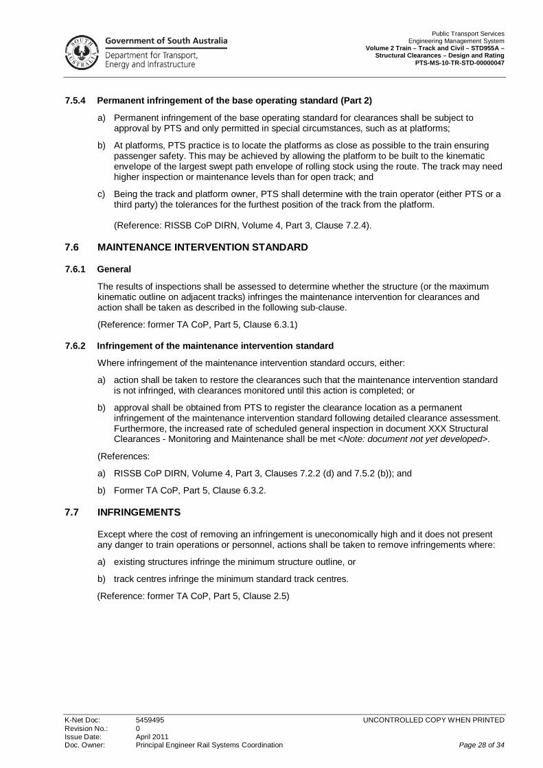
7.5.4 Permanent infringement of the base operating standard (Part 2)
a) Permanent infringement of the base operating standard for clearances shall be subject to approval by PTS and only permitted in special circumstances, such as at platforms;
b) At platforms, PTS practice is to locate the platforms as close as possible to the train ensuring passenger safety. This may be achieved by allowing the platform to be built to the kinematic envelope of the largest swept path envelope of rolling stock using the route. The track may need higher inspection or maintenance levels than for open track; and
c) Being the track and platform owner, PTS shall determine with the train operator (either PTS or a third party) the tolerances for the furthest position of the track from the platform. (Reference: RISSB CoP DIRN, Volume 4, Part 3, Clause 7.2.4).
7.6 MAINTENANCE INTERVENTION STANDARD
7.6.1 General
The results of inspections shall be assessed to determine whether the structure (or the maximum kinematic outline on adjacent tracks) infringes the maintenance intervention for clearances and action shall be taken as described in the following sub-clause.
(Reference: former TA CoP, Part 5, Clause 6.3.1)
7.6.2 Infringement of the maintenance intervention standard
Where infringement of the maintenance intervention standard occurs, either:
a) action shall be taken to restore the clearances such that the maintenance intervention standard is not infringed, with clearances monitored until this action is completed; or
b) approval shall be obtained from PTS to register the clearance location as a permanent infringement of the maintenance intervention standard following detailed clearance assessment. Furthermore, the increased rate of scheduled general inspection in document XXX Structural Clearances - Monitoring and Maintenance shall be met <Note: document not yet developed>.
(References:
a) RISSB CoP DIRN, Volume 4, Part 3, Clauses 7.2.2 (d) and 7.5.2 (b)); and
b) Former TA CoP, Part 5, Clause 6.3.2.
7.7 INFRINGEMENTS
Except where the cost of removing an infringement is uneconomically high and it does not present any danger to train operations or personnel, actions shall be taken to remove infringements where:
a) existing structures infringe the minimum structure outline, or
b) track centres infringe the minimum standard track centres.
(Reference: former TA CoP, Part 5, Clause 2.5)

Public Transport Services Engineering Management System Volume 2 Train – Track and Civil – STD955A – Structural Clearances – Design and Rating PTS-MS-10-TR-STD-00000047
K-Net Doc: 5459495 UNCONTROLLED COPY WHEN PRINTED Revision No.: 0 Issue Date: April 2011 Doc. Owner: Principal Engineer Rail Systems Coordination Page 29 of 34
8.0 DOCUMENTATION
8.1 GENERAL
A register providing information on all structural clearance issues shall be established and maintained in accordance with the PTS EMS introductory document referenced in Clause 1.1.
All locations on a line section where structures (or the maximum kinematic rolling stock outline on an adjacent track) infringe on the adopted structure outline shall be placed on this register.
Documentation shall include clearance classification of each track section in terms of the standards adopted.
For a given line section, the maximum kinematic rolling stock outline on an adjacent track may be treated in a similar way to a structure over or adjacent the line.
(Reference: RISSB CoP DIRN, Volume 4, Part 3, Clause 7.2.8)
8.2 DOCUMENTATION OF INFRINGEMENTS
Documentation, which includes registers and drawings, shall be maintained of:
a) Structures and allowable infringements in accordance with Clause 3.2.1;
b) Platforms in accordance with Clause 3.2.2; and
c) Tracks in accordance with Clause 3.2.4.
(Reference: former TA CoP Part 5, Clause 8.0)
Public Transport Services Engineering Management System Volume 2 Train – Track and Civil – STD955A – Structural Clearances – Design and Rating PTS-MS-10-TR-STD-00000047
K-Net Doc: 5459495 UNCONTROLLED COPY WHEN PRINTED Revision No.: 0 Issue Date: April 2011 Doc. Owner: Principal Engineer Rail Systems Coordination Page 30 of 34
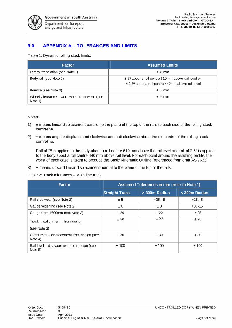
9.0 APPENDIX A – TOLERANCES AND LIMITS
Table 1: Dynamic rolling stock limits.
Factor Assumed Limits Lateral translation (see Note 1) ± 40mm
Body roll (see Note 2) ± 2º about a roll centre 610mm above rail level or ± 2.5º about a roll centre 440mm above rail level
Bounce (see Note 3) + 50mm
Wheel Clearance – worn wheel to new rail (see Note 1)
± 20mm
Notes:
1) ± means linear displacement parallel to the plane of the top of the rails to each side of the rolling stock centreline.
2) ± means angular displacement clockwise and anti-clockwise about the roll centre of the rolling stock centreline. Roll of 2º is applied to the body about a roll centre 610 mm above the rail level and roll of 2.5º is applied to the body about a roll centre 440 mm above rail level. For each point around the resulting profile, the worst of each case is taken to produce the Basic Kinematic Outline (referenced from draft AS 7633).
3) + means upward linear displacement normal to the plane of the top of the rails.
Table 2: Track tolerances – Main line track
Factor Assumed Tolerances in mm (refer to Note 1)
Straight Track > 300m Radius < 300m Radius Rail side wear (see Note 2) ± 5 +25, -5 +25, -5
Gauge widening (see Note 2) ± 0 ± 0 +0, -15
Gauge from 1600mm (see Note 2) ± 20 ± 20 ± 25
Track misalignment – from design
(see Note 3)
± 50 ± 50 ± 75
Cross level – displacement from design (see Note 4)
± 30 ± 30 ± 30
Rail level – displacement from design (see Note 5)
± 100 ± 100 ± 100

Public Transport Services Engineering Management System Volume 2 Train – Track and Civil – STD955A – Structural Clearances – Design and Rating PTS-MS-10-TR-STD-00000047
K-Net Doc: 5459495 UNCONTROLLED COPY WHEN PRINTED Revision No.: 0 Issue Date: April 2011 Doc. Owner: Principal Engineer Rail Systems Coordination Page 31 of 34
For the horizontal effect at station platforms: for the Kinematic Rolling Stock Outline to be compatible with the Platform Outline profile (i.e. 1 600mm from track centre and 1 200mm high) it shall be necessary to reduce the kinematic rolling stock outline past platforms by 75mm in width. This can be achieved as follows:
Table 3: Track tolerances – Stations – Horizontal Effects
Parameter National Code indicates PTS allowable reduction to
Amount of Reduction
Lateral translation of the vehicle body
40mm 40mm 0
Wheel clearance 20mm 20mm 0
Rail side wear 5mm Nil* 5mm
Gauge widening 20mm Nil* 20mm
Track alignment 50mm Nil* 50mm
Rotation 33mm 33mm 0
Cant effect 22mm 22mm 0
TOTAL = 190mm 115mm 75mm
* Can be Nil because platform clearance is measured from gauge face of near rail and is thus not affected by rail wear or wide gauge.
It will be seen that the reduction is actually 5mm more than required thus giving a small margin to allow for deterioration between inspections.
Notes:
1) These geometry tolerances are intended for the purpose of calculating clearances only.
2) On straight track, ± means linear displacement parallel to the plane of the top of the rails to each side of the design centreline of the track. On curved track, + means linear displacement to the outside of the curve and – means linear displacement to the inside of the curve, parallel to the plane of the tops of the rails.
3) On straight track, ± means horizontal linear displacement each side of the design centreline of the track. On curved track, + means horizontal displacement to the outside of the curve and – means horizontal linear displacement to the inside of the curve.
4) ± means vertical displacement of the left and right rails respectively resulting in a clockwise and an anti-clockwise rotation of the track in the vertical plane normal to the track.
5) ± means vertical linear displacement above (+) and below (-) design rail level.
(References:
a) RISSB CoP DIRN, Volume 4, Part 3, Tables 7.1 and 7.2; and
b) Former TA CoP, Part 5, Appendix 4)

Public Transport Services Engineering Management System Volume 2 Train – Track and Civil – STD955A – Structural Clearances – Design and Rating PTS-MS-10-TR-STD-00000047
K-Net Doc: 5459495 UNCONTROLLED COPY WHEN PRINTED Revision No.: 0 Issue Date: April 2011 Doc. Owner: Principal Engineer Rail Systems Coordination Page 32 of 34
10.0 APPENDIX B – CLEARANCE STANDARDS DESIGN PROCEDURES
10.1 B 1: STATIC ROLLING STOCK OUTLINE
a) Reference shall be made to AS 7507.3 for this procedure;
b) The Reference Static Outline for the rolling stock operating on a track section shall be as indicated in Clause 3.2.3;
c) The Candidate Static Outline is the static outline for the actual rolling stock operating on a track section – this is not the Static Rolling Stock Outline shown in Clause 3.2.3;
d) The Candidate Static Outline shall meet the requirements of Clause 3.2.3 and AS 7507.3 Clause 2.1 under all maintenance and loading conditions (eg. at all wheel diameters in the range for new and condemnable worn wheels).
(References: RISSB CoP DIRN, Volume 4, Part 3, Appendix B1)
10.2 B 2: VEHICLE SWEPT PATH
The centre throw (C in mm) and end throw (E in mm) of rolling stock on circular curved track shall be calculated as follows:
C = B2 / 8R ...(Eq. C1)
and
E = (L2 - B2) / 8R ...(Eq. C2)
where:
B = length between pivot centres of bogies (mm)
L = overall length of vehicle (mm)
R = radius of curve (mm)
The swept path shall be based on the Candidate Static Outline operating on the section of track under consideration as follows:
a) On straight (tangent) track the swept path shall meet the requirements of AS 7507.3; and
b) On circular curved track down to 100 m radius the swept path shall meet the requirements of AS 7507.3.
(References: RISSB CoP DIRN, Volume 4, Part 3, Appendix B2 and AS 7507.3)
10.3 B 3: TRACK TOLERANCES
Track tolerances shall be determined for the line section being considered for the following:
a) Rail side wear;
b) Gauge widening on curved track;
c) Gauge 1600 mm;
d) Track alignment from design (refer to Note);
e) Cross level from design (refer to Note); and
f) Rail level from design (refer to Note).
NOTE: The design track position shall be known as well as these tolerances.

Public Transport Services Engineering Management System Volume 2 Train – Track and Civil – STD955A – Structural Clearances – Design and Rating PTS-MS-10-TR-STD-00000047
K-Net Doc: 5459495 UNCONTROLLED COPY WHEN PRINTED Revision No.: 0 Issue Date: April 2011 Doc. Owner: Principal Engineer Rail Systems Coordination Page 33 of 34
(References: RISSB CoP DIRN, Volume 4, Part 3, Appendix B3 and AS 7507.3)
10.4 B 4: DYNAMIC ROLLING STOCK LIMITS
The dynamic rolling stock limits shall be determined in conjunction with operators for the following displacements:
a) Linear, to each side of the vehicle centreline and parallel to the plane of the top of the rails for lateral translation and for wheel clearance (worn wheel to new rail);
b) Angular, clockwise and anti-clockwise about the roll centre, for body roll; and
c) Upward linear displacement normal to the plane of the top of the rails, for bounce.
(Reference: RISSB CoP DIRN, Volume 4, Part 3, Appendix B4)
10.5 B 5: MAXIMUM KINEMATIC ROLLING STOCK OUTLINE
The kinematic envelope for an item of rolling stock shall represent the largest possible profile it can assume under the most adverse conditions.
It shall be determined for the particular track section using the following procedures:
a) Determine the static rolling stock outline (on straight, uncanted track) for the rolling stock operating on the line section;
b) For each point on the static rolling stock outline, apply horizontal displacements to widen the outline on each side of its vertical centreline for:
i. rolling stock lateral translation;
ii. wheel clearance (worn wheel to new rail);
iii. rail side wear;
iv. gauge widening of the track;
v. gauge tolerance of the track; and
vi. centre and end throw of the rolling stock on curved track.
c) From Step (b), apply vertical displacements to extend the outline vertically for rolling stock bounce;
d) From Step (c), apply angular displacements about the point of cant rotation for cant;
e) From Step (d), apply angular displacements about the left hand rail for cross level tolerance;
f) From Step (d), apply angular displacements about the right hand rail for cross level tolerance;
g) From Steps (e) and (f), apply angular displacements about the roll centre of the vehicle for body roll. (In the case of tilt trains, apply additional angular displacements about the tilt centre for body tilt.);
h) From Steps (e), (f ) and (g), apply horizontal displacements for track alignment tolerances, and vertical displacements for rail level tolerances;
i) The maximum envelope from steps (e), (f ), (g) and (h) defines the maximum kinematic rolling stock outline.
(Reference: RISSB CoP DIRN, Volume 4, Part 3, Appendix B5)

Public Transport Services Engineering Management System Volume 2 Train – Track and Civil – STD955A – Structural Clearances – Design and Rating PTS-MS-10-TR-STD-00000047
K-Net Doc: 5459495 UNCONTROLLED COPY WHEN PRINTED Revision No.: 0 Issue Date: April 2011 Doc. Owner: Principal Engineer Rail Systems Coordination Page 34 of 34
10.6 B 6: AIR GAP PROVISION
The provision of an air gap between the maximum kinematic rolling stock outline and structures (or maximum kinematic rolling stock outlines on adjacent tracks, see Note) shall take into account the following:
a) Base operating standards, maintenance intervention standards, and structure outlines;
b) Inspection intervals;
c) Variations in and rates of change of the parameters used to determine the maximum kinematic rolling stock outline; and
d) Potential for movement of the structure.
NOTE: For a given line section the maximum kinematic rolling stock outline on an adjacent line may be treated in a similar way to a structure over the line.
(Reference: RISSB CoP DIRN, Volume 4, Part 3, Appendix B6)
10.7 B 7: BASE OPERATING STANDARD
An air gap shall be added to the maximum kinematic rolling stock outline to define the base operating standard for clearances to structures or to the maximum kinematic rolling stock outline on adjacent tracks.
This air gap shall provide a safety margin against infringement of the maximum kinematic rolling stock outline.
(Reference: RISSB CoP DIRN, Volume 4, Part 3, Appendix B7)
10.8 B 8: MAINTENANCE INTERVENTION STANDARD
An air gap shall be added to the base operating standard to define the maintenance intervention standard for clearances to structures or to the maximum kinematic rolling stock outline on adjacent tracks.
This air gap shall provide for maintenance action to be taken before infringement of the base operating standard.
(Reference: RISSB CoP DIRN, Volume 4, Part 3, Appendix B8)
10.9 B 8: STRUCTURE OUTLINE
An air gap should be added to the maintenance intervention standard to define the structure outline for clearances to structures or to the maximum kinematic rolling stock outline on adjacent tracks.
This air gap should provide an additional safety margin such that scheduled inspections are not considered necessary for structures (or maximum kinematic rolling stock outlines on adjacent tracks) which fall outside this outline.
(Reference: RISSB CoP DIRN, Volume 4, Part 3, Appendix B9)

![TRACK AND CIVIL INFRASTRUCTURE CODE OF PRACTICE VOLUME TWO - TRAIN SYSTEM … · 2014-03-18 · CODE OF PRACTICE - VOLUME TWO - TRAIN SYSTEM [CP2] TRANSADELAIDE INFRASTRUCTURE SERVICES](https://img.pdfslide.net/doc/110x75/5e91b6e729f9d57b8f382b1f/track-and-civil-infrastructure-code-of-practice-volume-two-train-system-2014-03-18.jpg)