Embed Size (px)
Citation preview
PUBLICATION VI
Chip morphology in drilling of conventional cast stainless steel with
HIPed NiTi coating
In: Proceedings of the 3rd International Conference on Research and Development in Mechanical Industry,
RaDMI 2003. Predrag, Dasic (ed.). Herceg Novi, Serbia and Montenegro, 19–23 September 2003. Pp. 1–8. ISBN 86-83803-06-6 in hard copy and
ISBN 86-83803-10-4 in electronic form on CD-ROM. Reprinted with permission from the publisher.
1
Plenary paper
CHIP MORPHOLOGY IN DRILLING OF CONVENTIONAL CAST STAINLESS STEEL WITH HIPED NiTi COATING
J. A. Paro, T. E. Gustafsson, J. Koskinen
VTT Industrial Systems, Espoo, FINLAND; Email: [email protected]
1
Plenary paper
CHIP MORPHOLOGY IN DRILLING OF CONVENTIONAL CAST STAINLESS STEEL WITH HIPED NiTi COATING
J. A. Paro, T. E. Gustafsson, J. Koskinen
VTT Industrial Systems, Espoo, FINLAND; Email: [email protected]
Summary: This study investigated chip morphology in drilling of HIPed (Hot Isostatic Pressed) NiTi-coated conventionally cast stainless steels with TiN and TiCN-coated cemented carbide tools. Near-equiatomic nickel-titanium alloy (NiTi) has many attractive material properties, such as pseudo-elasticity and shape memory effects, which result in properties beneficial for use in cavitation-resistant coatings in addition to its well-known shape memory properties. Stainless steels are often considered to be poorly machinable materials; materials with high elasticity are also difficult to machine. In the drilling of stainless steel with a pseudo-elastic coating material, machinability difficulties are caused by the high strength and work hardening rate of steel and the pseudo-elastic properties of the coating material. In this study, drilling tests were carried out by a machining centre. The chip morphology was studied by analysing cemented carbide drills and chips. The interface between stainless steel and NiTi coating was examined using SEM (Scanning Electron Microscopy) and EDS (Energy Dispersive Spectroscopy) analysis. The effect of feed rate and cutting fluid supply on chip formation and tool wear was analysed. The cutting tests indicated that cutting speeds of 50 m/min, a feed rate of 0.1-0.2 mm/rev, and solid carbide drills can be applied, from a machinability standpoint. A HIPed pseudo-elastic coating decreases machinability. When effective cutting speeds and feed rates were used, optimal tool life was achieved without a deterioration in coating properties. Keywords: drilling, stainless steel, NiTi coating
1. INTRODUCTION Austenitic stainless steels are considered to be difficult to machine. Built-up edge (BUE) and irregular wear situations are often faced in machining operations. Difficulties from the machining point of view increase when duplex and high-strength stainless steels are to be machined. [1] In the drilling operation, small, well-broken chips are desirable. During drilling and formation, the chips rotate with the drill and impact the hole wall or interior of the flute. Once the bending moment has caused the critical strain, fracturing will occur. One important characteristic of Shape Memory Alloys (SMAs) is their super-elastic property. The NiTi polycrystalline SMA has, due to its unique bio-compatibility and super-elasticity, been successfully used to manufacture medical devices in recent years. One of the most dramatic examples is the utility of super-elastic coatings. Near-equiatomic nickel-titanium alloys (NiTi) have many properties that make them attractive for engineering applications, such as pseudo-elasticity and good cavitation resistivity, in addition to their more well-known shape memory properties [2, 3], while both technical and commercial limitations arise when NiTi is considered as a material for large engineering components. Consequently, interest in NiTi-coating technologies is on the rise. One of the principal challenges in NiTi coating is how to achieve adequate adhesion between NiTi and the substrate material. It is known that Hot Isostatic Pressing (HIP) can be used to produce bulk NiTi components from powders [4, 5, 6]. In the present study, machining of NiTi-coated stainless steels is investigated as a potential NiTi-coating method for stainless steels. 2. MATERIALS First, the samples used in the drilling tests were machined from the stainless steel blocks (X2CrNi 19 11). The nominal composition of the test steel is presented in Table 1. The capsule (Figure 1a) for HIP operation was welded from stainless steel plate (AISI 316) onto this block. The capsule was filled with rotating disc atomised
3rd International Conference ″Research and Development in Mechanical Industry″
RaDMI 2003 19 - 23. September 2003, Herceg Novi, Serbia and Montenegro
VI/1
2
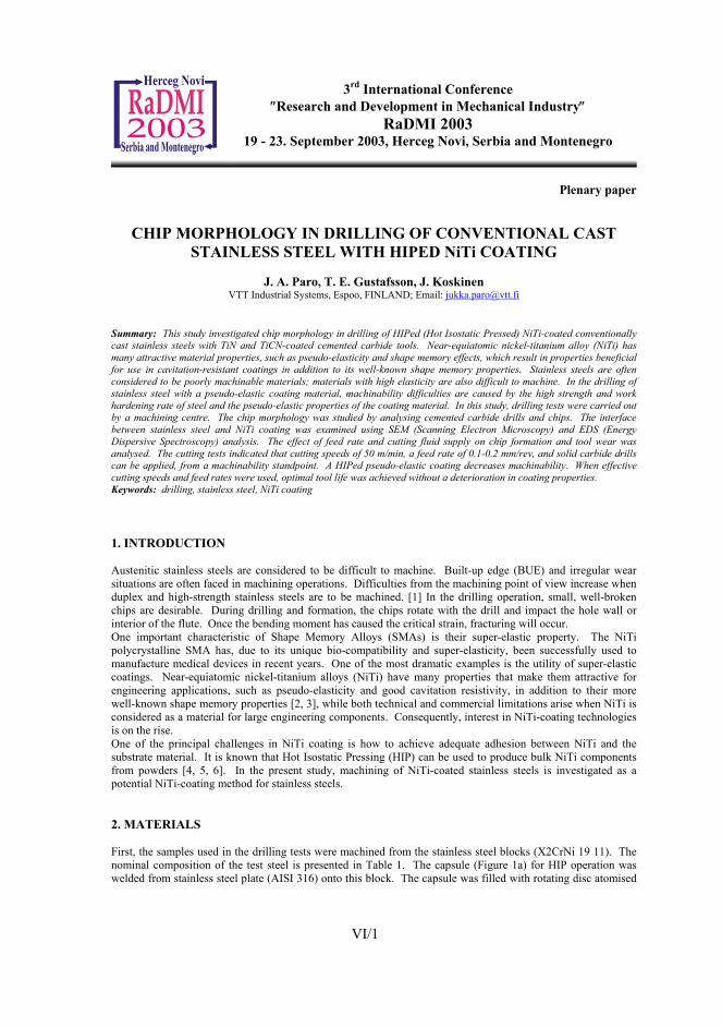
NiTi powder (FUKUDA) with an average particle size of 0.23 mm and composition 49.4±4.7 at-% Ni and 50.6±4.7 at-% Ti. The target bulk material composition (Ni/Ti) in at-% is 50/50, which in wt-% is 55/45. After the HIPing of the NiTi powder onto the block, the capsule was removed with a solid carbide milling tool for later drilling tests.
2
NiTi powder (FUKUDA) with an average particle size of 0.23 mm and composition 49.4±4.7 at-% Ni and 50.6±4.7 at-% Ti. The target bulk material composition (Ni/Ti) in at-% is 50/50, which in wt-% is 55/45. After the HIPing of the NiTi powder onto the block, the capsule was removed with a solid carbide milling tool for later drilling tests.
Figure 1: The HIPing capsule
Table 1: The nominal composition of the steel used in the drilling experiment % C % Mn % S % P % Cr % Ni % Si % V 0.03 1.20 0.015 0.04 18.4 9.2 0.4 0.06
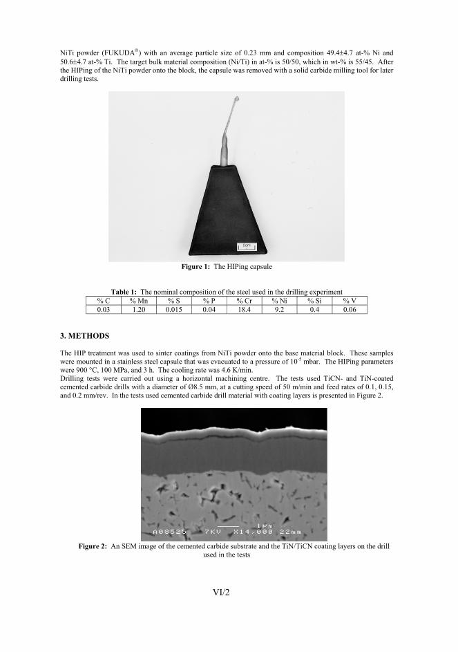
3. METHODS The HIP treatment was used to sinter coatings from NiTi powder onto the base material block. These samples were mounted in a stainless steel capsule that was evacuated to a pressure of 10-5 mbar. The HIPing parameters were 900 °C, 100 MPa, and 3 h. The cooling rate was 4.6 K/min. Drilling tests were carried out using a horizontal machining centre. The tests used TiCN- and TiN-coated cemented carbide drills with a diameter of Ø8.5 mm, at a cutting speed of 50 m/min and feed rates of 0.1, 0.15, and 0.2 mm/rev. In the tests used cemented carbide drill material with coating layers is presented in Figure 2.
Figure 2: An SEM image of the cemented carbide substrate and the TiN/TiCN coating layers on the drill
used in the tests
VI/2
Figure 1: The HIPing capsule
Table 1: The nominal composition of the steel used in the drilling experiment % C % Mn % S % P % Cr % Ni % Si % V 0.03 1.20 0.015 0.04 18.4 9.2 0.4 0.06
3. METHODS The HIP treatment was used to sinter coatings from NiTi powder onto the base material block. These samples were mounted in a stainless steel capsule that was evacuated to a pressure of 10-5 mbar. The HIPing parameters were 900 °C, 100 MPa, and 3 h. The cooling rate was 4.6 K/min. Drilling tests were carried out using a horizontal machining centre. The tests used TiCN- and TiN-coated cemented carbide drills with a diameter of Ø8.5 mm, at a cutting speed of 50 m/min and feed rates of 0.1, 0.15, and 0.2 mm/rev. In the tests used cemented carbide drill material with coating layers is presented in Figure 2.
Figure 2: An SEM image of the cemented carbide substrate and the TiN/TiCN coating layers on the drill
used in the tests
VI/2
3
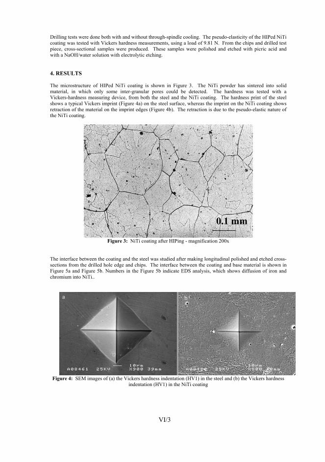
Drilling tests were done both with and without through-spindle cooling. The pseudo-elasticity of the HIPed NiTi coating was tested with Vickers hardness measurements, using a load of 9.81 N. From the chips and drilled test piece, cross-sectional samples were produced. These samples were polished and etched with picric acid and with a NaOH/water solution with electrolytic etching. 4. RESULTS The microstructure of HIPed NiTi coating is shown in Figure 3. The NiTi powder has sintered into solid material, in which only some inter-granular pores could be detected. The hardness was tested with a Vickers-hardness measuring device, from both the steel and the NiTi coating. The hardness print of the steel shows a typical Vickers imprint (Figure 4a) on the steel surface, whereas the imprint on the NiTi coating shows retraction of the material on the imprint edges (Figure 4b). The retraction is due to the pseudo-elastic nature of the NiTi coating.
3
Drilling tests were done both with and without through-spindle cooling. The pseudo-elasticity of the HIPed NiTi coating was tested with Vickers hardness measurements, using a load of 9.81 N. From the chips and drilled test piece, cross-sectional samples were produced. These samples were polished and etched with picric acid and with a NaOH/water solution with electrolytic etching. 4. RESULTS The microstructure of HIPed NiTi coating is shown in Figure 3. The NiTi powder has sintered into solid material, in which only some inter-granular pores could be detected. The hardness was tested with a Vickers-hardness measuring device, from both the steel and the NiTi coating. The hardness print of the steel shows a typical Vickers imprint (Figure 4a) on the steel surface, whereas the imprint on the NiTi coating shows retraction of the material on the imprint edges (Figure 4b). The retraction is due to the pseudo-elastic nature of the NiTi coating.
Figure 3: NiTi coating after HIPing - magnification 200x
The interface between the coating and the steel was studied after making longitudinal polished and etched cross-sections from the drilled hole edge and chips. The interface between the coating and base material is shown in Figure 5a and Figure 5b. Numbers in the Figure 5b indicate EDS analysis, which shows diffusion of iron and chromium into NiTi..
Figure 4: SEM images of (a) the Vickers hardness indentation (HV1) in the steel and (b) the Vickers hardness
indentation (HV1) in the NiTi coating
VI/3
4 4
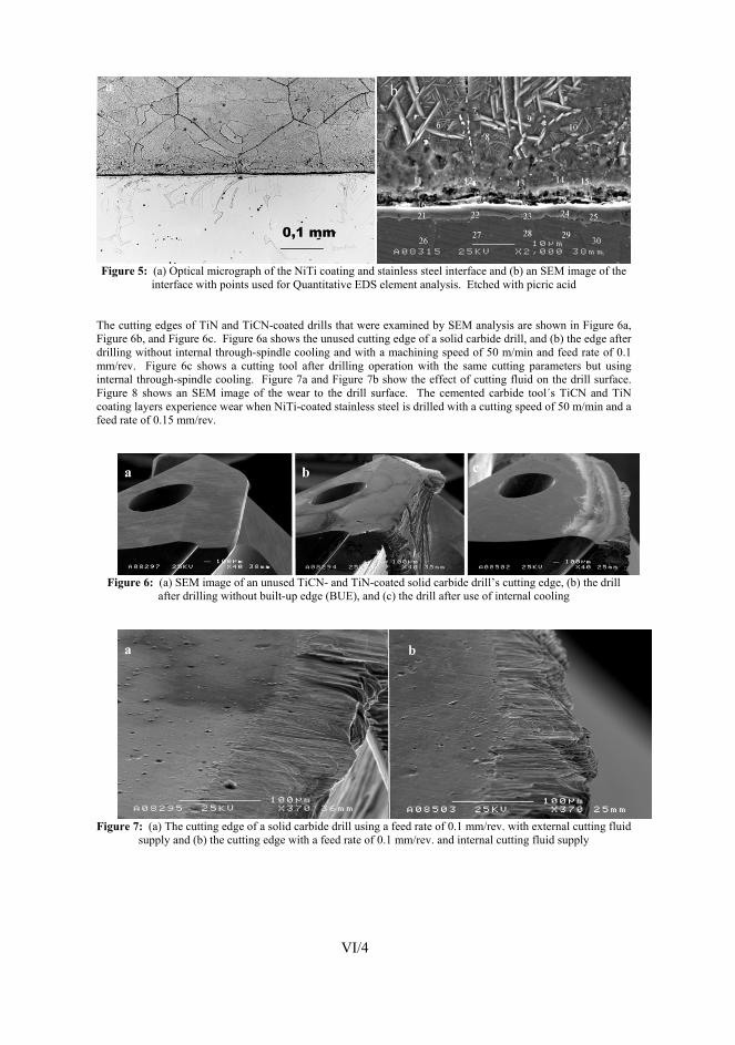
Figure 5: (a) Optical micrograph of the NiTi coating and stainless steel interface and (b) an SEM image of the
interface with points used for Quantitative EDS element analysis. Etched with picric acid The cutting edges of TiN and TiCN-coated drills that were examined by SEM analysis are shown in Figure 6a, Figure 6b, and Figure 6c. Figure 6a shows the unused cutting edge of a solid carbide drill, and (b) the edge after drilling without internal through-spindle cooling and with a machining speed of 50 m/min and feed rate of 0.1 mm/rev. Figure 6c shows a cutting tool after drilling operation with the same cutting parameters but using internal through-spindle cooling. Figure 7a and Figure 7b show the effect of cutting fluid on the drill surface. Figure 8 shows an SEM image of the wear to the drill surface. The cemented carbide tool´s TiCN and TiN coating layers experience wear when NiTi-coated stainless steel is drilled with a cutting speed of 50 m/min and a feed rate of 0.15 mm/rev.
Figure 6: (a) SEM image of an unused TiCN- and TiN-coated solid carbide drill’s cutting edge, (b) the drill
after drilling without built-up edge (BUE), and (c) the drill after use of internal cooling
Figure 7: (a) The cutting edge of a solid carbide drill using a feed rate of 0.1 mm/rev. with external cutting fluid
supply and (b) the cutting edge with a feed rate of 0.1 mm/rev. and internal cutting fluid supply
VI/4
5 5
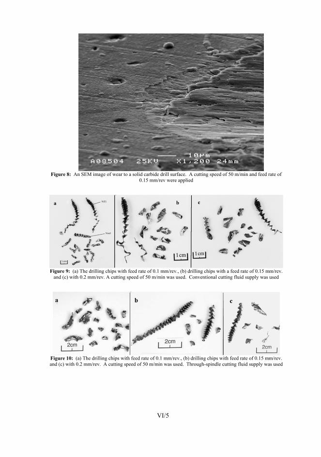
Figure 8: An SEM image of wear to a solid carbide drill surface. A cutting speed of 50 m/min and feed rate of
0.15 mm/rev were applied
Figure 9: (a) The drilling chips with feed rate of 0.1 mm/rev., (b) drilling chips with a feed rate of 0.15 mm/rev.
and (c) with 0.2 mm/rev. A cutting speed of 50 m/min was used. Conventional cutting fluid supply was used
Figure 10: (a) The drilling chips with feed rate of 0.1 mm/rev., (b) drilling chips with feed rate of 0.15 mm/rev. and (c) with 0.2 mm/rev. A cutting speed of 50 m/min was used. Through-spindle cutting fluid supply was used
VI/5
6 6
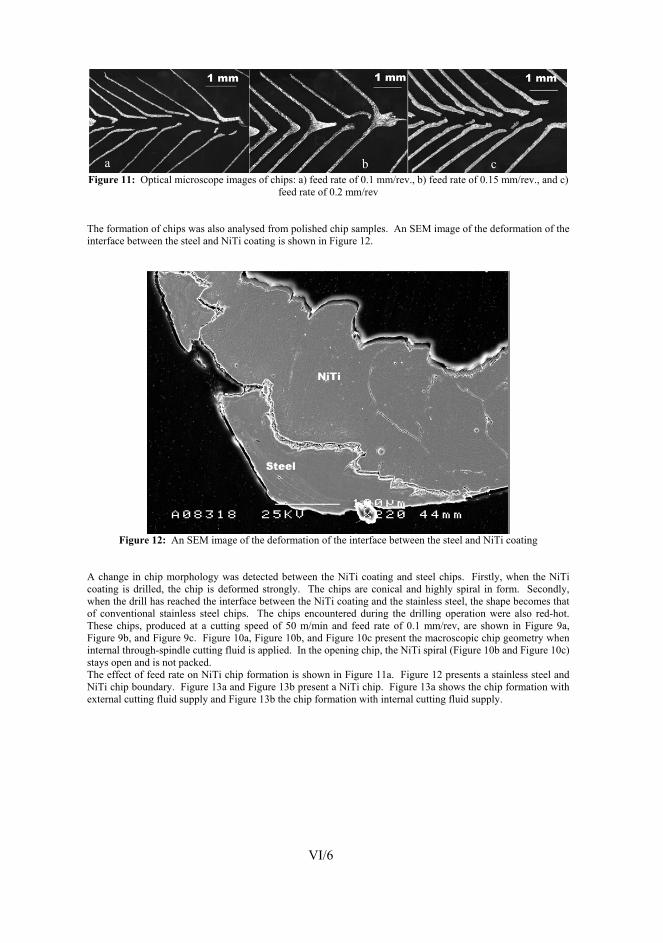
Figure 11: Optical microscope images of chips: a) feed rate of 0.1 mm/rev., b) feed rate of 0.15 mm/rev., and c)
feed rate of 0.2 mm/rev The formation of chips was also analysed from polished chip samples. An SEM image of the deformation of the interface between the steel and NiTi coating is shown in Figure 12.
Figure 12: An SEM image of the deformation of the interface between the steel and NiTi coating
A change in chip morphology was detected between the NiTi coating and steel chips. Firstly, when the NiTi coating is drilled, the chip is deformed strongly. The chips are conical and highly spiral in form. Secondly, when the drill has reached the interface between the NiTi coating and the stainless steel, the shape becomes that of conventional stainless steel chips. The chips encountered during the drilling operation were also red-hot. These chips, produced at a cutting speed of 50 m/min and feed rate of 0.1 mm/rev, are shown in Figure 9a, Figure 9b, and Figure 9c. Figure 10a, Figure 10b, and Figure 10c present the macroscopic chip geometry when internal through-spindle cutting fluid is applied. In the opening chip, the NiTi spiral (Figure 10b and Figure 10c) stays open and is not packed. The effect of feed rate on NiTi chip formation is shown in Figure 11a. Figure 12 presents a stainless steel and NiTi chip boundary. Figure 13a and Figure 13b present a NiTi chip. Figure 13a shows the chip formation with external cutting fluid supply and Figure 13b the chip formation with internal cutting fluid supply.
VI/6
7 7
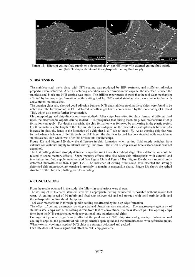
Figure 13: Effect of cutting fluid supply on chip morphology: (a) NiTi chip with external cutting fluid supply
and (b) NiTi chip with internal through-spindle cutting fluid supply 5. DISCUSSION The stainless steel work piece with NiTi coating was produced by HIP treatment, and sufficient adhesion properties were achieved. After a machining operation was performed on the capsule, the interface between the stainless steel block and NiTi coating was intact. The drilling experiments showed that the tool wear mechanism affected by built-up edge formation on the cutting tool for NiTi-coated stainless steel was similar to that with conventional stainless steel. The opening chips also showed good adhesion between NiTi and stainless steel, as these chips were found to be unbroken. The formation of the BUE detected in drills might have been enhanced by the tool coating (TiCN and TiN), which also merits further investigation. Chip morphology and chip dimensions were studied. After chip observation for chips formed at different feed rates, the macroscopic aspects can be studied. It is recognised that during machining, two mechanisms of chip formation can apply. For ductile materials, the chip formation was followed by a shearing in the plastic region. For these materials, the length of the chip and its thickness depend on the material´s elasto-plastic behaviour. An increase in plasticity leads to the formation of a chip that is difficult to break [7]. As an opening chip that was formed when a hole was drilled through the NiTi layer, the chip was formed fan concatenated with long tubular stainless steel, chip which was after that broken into smaller chips. Figure 12a and Figure 12b show the difference in chip formation when cutting fluid supply switches from external conventional supply to internal cutting fluid flow. The effect of chip size on hole surface finish was not examined. The first drilling showed strongly deformed chips that went through a red-hot stage. Their deformation could be related to shape memory effects. Shape memory effects arise also when chip micrographs with external and internal cutting fluid supply are compared (see Figure 13a and Figure 13b). Figure 13a shows a more strongly deformed microstructure than Figure 13b. The influence of cutting fluid could have affected the strongly deformed chip microstructure, causing it propably to remain in martensitic phase. Figure 13a shows the retired structure of the chip after drilling with less cooling. 6. CONCLUSIONS From the results obtained in the study, the following conclusions were drawn. The drilling of NiTi-coated stainless steel with appropriate cutting parameters is possible without severe tool wear. A cutting speed of 50 m/min and feed rate between 0.1 and 0.2 mm/rev with solid carbide drills and through-spindle cooling should be applied. Tool wear mechanisms in through-spindle cooling are affected by built up edge formation The effect of cutting parameters on chip size and formation was examined. The macroscopic geometry of stainless steel chips with NiTi coating differs from that of conventional stainless steel chips. The opening chips form from the NiTi concatenated with conventional long stainless steel chips. Cutting-fluid presence significantly affected the predominant NiTi chip size and geometry. When internal cooling is applied, the geometry of NiTi chips remains open-spiral and the microstructure with deformed grains. When external cooling is applied, NiTi chips are strongly deformed and packed. Feed rate does not have a significant effect on NiTi chip geometry.
VI/7
8
ACKNOWLEDGEMENTS The authors are thankful to Sulzer Pumps Finland for providing the stainless steel materials that were tested. REFERENCES [1] L. Jiang, H. Hänninen, J. Paro, and V. Kauppinen, Active Wear and Failure Mechanisms of TiN-Coated High
Speed Steel and TiN-Coated Cemented Carbide Tools When Machining Powder Metallurgically Made Stainless Steels. Metallurgical and Materials Transactions, 27A (1996) 9, 2796-2808.
[2] Z. Li and Q. Sun, The initation and growth of macroscopic martensite band in nano-grained NiTi microtube under tension. International Journal of Plasticity 18 (2002), 1481-1498.
[3] D. Starosvetsky and I. Gotman, TiN coating improves the corrosion behaviour of superelastic NiTi surgical alloy. Surface and Coatings Technology 148 (2001), 268-276.
[4] G. Wang, Welding of Nitinol to Stainless Steel. Proceedings of SMST-97, 1997, 131-136. [5] J. Koskinen, E. Haimi, A. Mahiout, V. Lindroos, and S-P. Hannula, Superelastic NiTi coatings with good
corrosive wear resistance. Proceedings of the International Conference on Martensitic Transformations (ICOMAT 02). Espoo, 2002, 10-14.
[6] J. Koskinen, E. Haimi, Method for Forming a Nickle-Titanium Plating, US Patent 6,458,317 (2002). [7] H., Schulz, Hochgeschwindigkeitsfräsen metalischer und nichtmetallischer Werkstoffe. Carl Hanser Verlag
1989. München Wien. 348 p.
VI/8