Embed Size (px)
Citation preview
1 of 1
Publications Transmittal
Transmittal Number Date PT 07-036
July 2007
Publication Distribution To: All holders of the Maintenance Manual Publication Title Publication Number
Maintenance Manual M 51-01 Originating Organization Maintenance and Operations Division Remarks: Please be aware that this revision is only available electronically. Who to Contact: Please contact Helen Simmonds at (360) 705-7866 with comments, questions, or suggestions for improvement to the Maintenance Manual. Available On-Line: To obtain the Maintenance Manual in its entirety, it is available on the Internet at: http://www.wsdot.wa.gov/publications/manuals/fulltext/M51-01/Maintenance.pdf Instructions: Page numbers and corresponding sheet-counts are given in the table below to indicate portions of the Maintenance Manual that are to be removed and inserted to accomplish this revision.
Remove Insert Chapter Pages Sheets Pages Sheets
Contents 1 - 9 5 1 - 9 5 Chapter 2 Work Zone Traffic Control and Safety 1 - 12 6 1 - 14 7 Chapter 8 Traffic Services 1 - 14 7 1 - 14 7 Distributed By Phone Number Signature
Directional Documents and Engineering Publications
(360) 705-7430 FAX: 705-6861

Maintenance Manual M 51-01.02 Contents-1 July 2007
Contents
Contents
Foreword i
Introduction ii
Chapter1 EmergencyProceduresGeneral Responsibilities .................................................................................................. 1-1Regional Emergency Response Plans .............................................................................. 1-2WSDOT Disaster Plan ..................................................................................................... 1-2
Concepts of Operations .......................................................................................... 1-2Organization and Assignment of Responsibilities ........................................................... 1-3Administration and Logistics ........................................................................................... 1-3Plan Development and Maintenance ............................................................................... 1-3Training and Exercises ..................................................................................................... 1-3Emergency Operating Procedures ................................................................................... 1-3 General.................................................................................................................... 1-3Maintenance Field Personnel ........................................................................................... 1-4Maintenance Superintendent or Supervisor ..................................................................... 1-5Abandoned Cargo ............................................................................................................ 1-6Clearing the Highway ...................................................................................................... 1-6 Open Road Policy ................................................................................................... 1-6
Chapter 2 Work Zone Traffic Control and SafetyGeneral ............................................................................................................................. 2-1Fundamental Principles ................................................................................................... 2-1Traffic Control Zones ....................................................................................................... 2-2Traffic Control Devices.................................................................................................... 2-3Cone Placement Procedure .............................................................................................. 2-5Traffic Control Procedures ............................................................................................... 2-9Off-Road Activities ........................................................................................................ 2-10Nighttime Activities ....................................................................................................... 2-10Automated Flagger Assistance Device (AFAD) ............................................................ 2-10Temporary and Portable Signal Systems ....................................................................... 2-11Non-motorized Traffic Control ...................................................................................... 2-11Pedestrian Control ......................................................................................................... 2-11Bicycle Control .............................................................................................................. 2-12Safety ............................................................................................................................. 2-12Work Zone Operations ................................................................................................... 2-12Enforcement ................................................................................................................... 2-13Resources for Traffic Control and Work Zone Safety ................................................... 2-13
Contents-2 Maintenance Manual M 51-01.02 July 2007
Contents
Chapter3 PavementPatching&RepairGeneral ............................................................................................................................. 3-1Maintenance of Flexible Pavements ............................................................................... 3-2Load & Speed Restrictions ............................................................................................. 3-2Pavement Deficiencies ..................................................................................................... 3-2
Rutting ............................................................................................... 3-2Alligator Cracking ............................................................................................... 3-2Longitudinal Cracking ............................................................................................ 3-3Transverse Cracking ............................................................................................... 3-3Potholes ............................................................................................... 3-3Raveling & Pitting ............................................................................................... 3-3Flushing ............................................................................................... 3-4Sags and Humps ............................................................................................... 3-4Edge Raveling ............................................................................................... 3-4
Pavement Maintenance Techniques ................................................................................. 3-4Patching ............................................................................................... 3-4
Patching with Base Repair ............................................................................................... 3-4Overlay Patches ............................................................................................... 3-6Spreader Box Patching ........................................................................................... 3-7Grader Patching ............................................................................................... 3-8Rolling Hot Mix Patches ........................................................................................ 3-8
Effects of Traffic on a Patching Operation ...................................................................... 3-9Crack Sealing (or Pouring) ............................................................................................ 3-10
Hot Pour Method ............................................................................................. 3-10Cold Pour Method ............................................................................................. 3-10
Maintenance of Rigid Pavements .................................................................................. 3-11Portland Cement Concrete Pavement Crack Pouring .................................................... 3-11Asphalt Emulsion Surface Treatment ............................................................................ 3-14
Fog Seals ............................................................................................. 3-14Sand Seal ............................................................................................. 3-14Aggregate (Chip) Seal .......................................................................................... 3-14
Pavement Conditions for a Successful Project .............................................................. 3-15Material Selection .......................................................................................................... 3-15
Asphalts and Emulsions ....................................................................................... 3-15Common Types of Emulsions Used for Chip Seals ............................................. 3-15Aggregate ............................................................................................. 3-16Weather ............................................................................................. 3-16Roadway Preparation ........................................................................................... 3-16Equipment ............................................................................................. 3-16
Maintenance Manual M 51-01.02 Contents-� July 2007
Contents
Distributor ............................................................................................. 3-16Calibration Procedures ................................................................................................... 3-17
Distributor Calibrations ........................................................................................ 3-17Nozzle Size ............................................................................................. 3-18Proper Pressure ............................................................................................. 3-18Spray Bar Height ............................................................................................. 3-20Proper Nozzle Angle ............................................................................................ 3-21Streaking Will Occur: ........................................................................................... 3-21
Cleaning of Distributor .................................................................................................. 3-21Checking the Bitumeter ................................................................................................. 3-22Traffic Control ............................................................................................................... 3-22Application of Asphalt ................................................................................................... 3-22Spreading Aggregate ...................................................................................................... 3-23Chip spreader Calibration .............................................................................................. 3-23Chip Spreader ................................................................................................................ 3-24Rolling ........................................................................................................................... 3-25Spreading of Fines or Choking - Optional ..................................................................... 3-25Post-Seal Inspection ....................................................................................................... 3-26DOs of Seal Coating ...................................................................................................... 3-26DO NOTs of Seal Coating ............................................................................................. 3-27Blade Mixed Asphalt Mix .............................................................................................. 3-27Handling Emulsified Asphalts ....................................................................................... 3-28
Chapter4 DrainageGeneral ............................................................................................................................. 4-1Drainage from Abutting Properties .................................................................................. 4-1Ditches and Gutters .......................................................................................................... 4-2Rockfall Ditches and Slope Benches ............................................................................... 4-3Dry Wells ......................................................................................................................... 4-3Culverts ............................................................................................................................ 4-3Automatic Pumps ............................................................................................................. 4-4Under Drains .................................................................................................................... 4-4Storm Sewers ................................................................................................................... 4-4Bank Protection ............................................................................................................... 4-5Detention Ponds and Tanks .............................................................................................. 4-6
Contents-� Maintenance Manual M 51-01.02 July 2007
Contents
Chapter 5 Maintenance of StructuresGeneral ............................................................................................................................. 5-1Bridge Repair Guidelines ................................................................................................ 5-4Bridge Information .......................................................................................................... 5-5Environmental Aspects .................................................................................................... 5-5Utility Installations .......................................................................................................... 5-7
Chapter6 RoadsideManagementGeneral ............................................................................................................................. 6-1Definitions ........................................................................................................................ 6-1Reference ......................................................................................................................... 6-2Resources ......................................................................................................................... 6-2Roadside Functions .......................................................................................................... 6-3Roadside Treatment ......................................................................................................... 6-3Maintenance Involvement in the Roadside Management Process .................................. 6-4Roadside Maintenance and the Maintenance Accountability Process ............................. 6-4Roadside Management Zones .......................................................................................... 6-5Typical Roadside Management Zones ............................................................................. 6-6Functional Zone Objectives ............................................................................................. 6-7Maintenance of Zone 1 .................................................................................................... 6-7
Policy ............................................................................................... 6-7Methods ............................................................................................... 6-8
Maintenance of Zone 2 .................................................................................................... 6-8Policy ............................................................................................... 6-8Methods ............................................................................................... 6-9
Maintenance of Zone 3 .................................................................................................. 6-10Policy ............................................................................................. 6-10Methods ............................................................................................. 6-10
Integrated Vegetation Management ............................................................................... 6-10Methods ......................................................................................................................... 6-11Danger Trees .................................................................................................................. 6-13Disposal of Logs Dumped on Right-of-Way ................................................................. 6-13Removal of Dangerous Objects and Structures ............................................................. 6-14Trespass and Encroachment ........................................................................................... 6-14Encroachments - General ............................................................................................... 6-14Encroachment - Maintenance Crew Responsibilities .................................................... 6-14Franchises and Permits .................................................................................................. 6-15The Use of Pesticides ..................................................................................................... 6-16Use and Evaluation of New Products ............................................................................ 6-16Pesticide License ........................................................................................................... 6-16
Maintenance Manual M 51-01.02 Contents-5 July 2007
Contents
Record Keeping ............................................................................................................. 6-17Product Labels ............................................................................................................... 6-17Posting Requirements .................................................................................................... 6-17Aquatic Pesticide Applications ...................................................................................... 6-17Pesticide Sensitive Individuals ...................................................................................... 6-17Container Disposal ........................................................................................................ 6-17Use of Mowing Equipment ............................................................................................ 6-18Other Cutting Methods .................................................................................................. 6-19Cultural Control Methods .............................................................................................. 6-19Biological Control ......................................................................................................... 6-19Burning Debris ............................................................................................................... 6-20Illegal Tree Removal ...................................................................................................... 6-20Significant Roadside Activities ...................................................................................... 6-21Definitions ...................................................................................................................... 6-21Notification .................................................................................................................... 6-21Removal of Debris and Rubbish .................................................................................... 6-22Litter Control and Partnerships for Roadside Enhancement ......................................... 6-22Adopt-a-Highway .......................................................................................................... 6-23Program Rules ............................................................................................................... 6-23Participant Eligibility ..................................................................................................... 6-23Assignment of Sections ................................................................................................. 6-24Volunteer Adoptions ...................................................................................................... 6-24Sponsored Adoptions ..................................................................................................... 6-25General Permits for Roadside Enhancement ................................................................. 6-26AAH Administrative Roles and Responsibilities .......................................................... 6-26Maintenance & Operations Responsibilities ................................................................. 6-26Region Responsibilities ................................................................................................. 6-27Auxiliary Facilities ........................................................................................................ 6-28
Safety Rest Areas ............................................................................................. 6-28Park and Ride Lots ............................................................................................. 6-28Historical Markers ............................................................................................. 6-29Viewpoints ............................................................................................. 6-29
Chapter 7 Snow and Ice ControlGeneral ............................................................................................................................. 7-1Preparation for Winter Operations ................................................................................... 7-1Highway Categories ......................................................................................................... 7-3Special Criteria ................................................................................................................ 7-4Work on State Highways ................................................................................................. 7-4City Streets on the State Highway System ...................................................................... 7-6
Contents-� Maintenance Manual M 51-01.02 July 2007
Contents
Work on Other Roads and Areas ...................................................................................... 7-6Abandoned or Illegally Parked Vehicles .......................................................................... 7-7Closures ........................................................................................................................... 7-7Emergency Assistance ..................................................................................................... 7-8Precautions ....................................................................................................................... 7-9Service Level Quality Measurement ............................................................................... 7-9
Chapter 8 Traffic ServicesGeneral ............................................................................................................................. 8-1Reconstruction Principles ................................................................................................ 8-1Signing ............................................................................................................................. 8-2Signing Responsibility ..................................................................................................... 8-2Sign Installation ............................................................................................................... 8-2Maintenance ..................................................................................................................... 8-3Sign Visibility .................................................................................................................. 8-4Sign Storage and Transportation ...................................................................................... 8-5Delineation ....................................................................................................................... 8-5Pavement Markings ......................................................................................................... 8-5Materials .......................................................................................................................... 8-8Application ...................................................................................................................... 8-8Surface Moisture Test ...................................................................................................... 8-8Marking Renewal or Replacement Frequency ................................................................ 8-8Removal of Markings ...................................................................................................... 8-9Guideposts ....................................................................................................................... 8-9Traffic Barriers and Impact Attenuators .......................................................................... 8-9Maintenance ..................................................................................................................... 8-9Inspection ......................................................................................................................... 8-9Repair ............................................................................................................................. 8-10Standard Run of Barrier ................................................................................................. 8-11Terminals and Anchors .................................................................................................. 8-11Transitions ..................................................................................................................... 8-12Impact Attenuators ......................................................................................................... 8-13Maintenance ................................................................................................................... 8-13Islands ............................................................................................................................ 8-13Transit Vehicle Stop Zones ............................................................................................ 8-13
Maintenance ............................................................................................. 8-13
Maintenance Manual M 51-01.02 Contents-7 July 2007
Contents
Chapter 9 Electrical System MaintenanceGeneral ............................................................................................................................. 9-1Wiring and Connection Maintenance .............................................................................. 9-1Enclosure Maintenance .................................................................................................... 9-1Documentation ................................................................................................................. 9-1Changeable Message Sign Systems ................................................................................. 9-1Drain Pump Systems ........................................................................................................ 9-2Gate and Barrier Systems ................................................................................................ 9-2
Minor ............................................................................................... 9-2Major ............................................................................................... 9-2
Intersection Control Beacons(Includes Hazard Beacons) ............................................... 9-2Illumination Systems ....................................................................................................... 9-2
Roadway Illumination Systems .............................................................................. 9-2Sign Lighting Systems ..................................................................................................... 9-3Services ............................................................................................................................ 9-3Signal Systems ................................................................................................................. 9-3Vehicle Detection Systems .............................................................................................. 9-3Pedestrian Detection and Display System ....................................................................... 9-3Vehicle Display Systems .................................................................................................. 9-3Signal Control Systems .................................................................................................... 9-4Sprinkler Systems ............................................................................................................ 9-4Television Systems .......................................................................................................... 9-4
Chapter 10 MiscellaneousRight of Way Fences ...................................................................................................... 10-1Road Approaches- General ............................................................................................ 10-1Typical Maintenance Responsibilities in Cities ............................................................. 10-1Maintenance Yards ......................................................................................................... 10-6Stockpile Sites ............................................................................................................... 10-6Materials from State Quarries or Pits ............................................................................ 10-7Procurement of Materials .............................................................................................. 10-7Material Specifications-General .................................................................................... 10-7Disposal of Surplus Items ............................................................................................. 10-8
Equipment ............................................................................................. 10-8Inventoried Items ............................................................................................. 10-8Non-Inventoried Items ......................................................................................... 10-8
Instructions for Radio Operation ................................................................................... 10-8General Technique ......................................................................................................... 10-8Helpful Reminders ......................................................................................................... 10-8Work Scheduling and Reporting .................................................................................... 10-9
Contents-� Maintenance Manual M 51-01.02 July 2007
Contents
Budget ............................................................................................................................ 10-9Scheduling ..................................................................................................................... 10-9Reporting ..................................................................................................................... 10-10Environmental Sensitivity ........................................................................................... 10-10
AcronymsandAbbreviations
Appendices
City Streets as Part of State HighwaysCity Streets as Part of State Highways ............................................................................ 1-2Agreed Upon Guidelines ................................................................................................. 1-2Concurrences ................................................................................................................... 1-9Concurrences with Recommendations for Acceptance ................................................... 1-9Recommendations Accepted ............................................................................................ 1-9
Figures
Index

Chapter 2 Work Zone Traffic Control and Safety
Maintenance Manual M 51-01.02 Page 2-1 July 2007
Chapter 2 Work Zone Traffic Control and Safety
GeneralSafe and effective traffic control is vital for the safety of the traveling public. It is also essential to protect construction, maintenance and utility workers whose work places them near high speed traffic. The traffic control guidelines in this manual provide the driving public positive and consistent guidance through work zones. These procedures will also reduce the risk to maintenance workers who are exposed to potential traffic hazards
The Secretary of Transportation has adopted the Manual on Uniform Traffic Control Devices (MUTCD) as the legal standard as required by RCW 47.36.030. It is mandatory that traffic control measures on maintenance projects comply with the MUTCD requirements. The MUTCD outlines basic principles and prescribes standards for the design, application, installation, and maintenance of traffic control devices. The MUTCD details requirements for color, size, shape, location and need for traffic control devices.
In some cases WSDOT has standards that exceed those in the MUTCD (e.g., see Traffic Manual, M 51-02, Chapter 5 and the Work Zone Traffic Control Guidelines Book, M 54-44). In such situations the most stringent standard is the legal standard you must follow. Learn those standards before you perform traffic control.
Consult the Regional Traffic Engineer when standard layouts are not applicable.
This chapter reflects the work and recommendations provided by the Work Zone Safety Task Force. The Work Zone Traffic Control Guidelines Book (M 54-44) incorporates the recommendations of the Work Zone Safety Task Force and the standards of the MUTCD, and is intended to be used as the companion resource to the guidance in this chapter.
The maintenance employee in charge at a work zone is responsible to see all standards are followed. This includes ensuring temporary signs, warning devices, and flag persons are placed appropriately to protect both motorists and workers. Motorist and worker safety are of primary importance. Safety takes precedence over all efforts to maintain a highway or structure.
Fundamental PrinciplesPrinciples to enhance motorist and worker safety in maintenance work areas:
• Develop a comprehensive traffic control strategy that can be implemented at the work site. Evaluation of the work operation, site, and traffic conditions should determine the traffic control measures to be utilized.
Work Zone Traffic Control and Safety Chapter 2
Page 2-2 Maintenance Manual M 51-01.02 July 2007
Refer to the Work Zone Traffic Control Guidelines Book, “checklist for establishing a temporary traffic control zone” and the Traffic Manual, “traffic control planning and strategy checklist”.
• Maintain traffic flow as close to normal highway situations as possible.
• Do not surprise the motorist. Locate and place devices to maintain adequate sight distance for driver recognition and reaction on straight highway sections if possible.
• Prepare, understand, and implement a traffic control plan. Don’t routinely rely on minimum standards. Evaluation of the work operation, site and traffic conditions should be determined to the appropriate level of traffic control measures.
• Avoid frequent and abrupt changes in alignment.
• Minimize worker exposure time to traffic.
• Provide adequate warning, delineation, and channelization.
• Remove inappropriate pavement markings on long-term projects. (Work occupying a location 3 days or more)
• Provide flagging only when other methods of traffic control are inadequate.
• Inspect traffic set-up control measures prior to work.
• Monitor traffic control and modify where changing traffic conditions warrant.
• Remove, cover, or turn control devices away from traffic when not needed or in use.
• Channelize traffic with pavement markings, signing, cones, plastic barrels, water filled barriers, or lightweight devices.
• Sand bags may be used for sign ballast. Do not use heavy, solid weights, (e.g., concrete blocks) for stabilizing portable sign supports.
• Traffic control measures must be selected and implemented with the drivers’ perspective in mind. Credible messages must be sent to the driver to provide a reasonable expectation that the driver will comply.
• Plan ahead for work operations and the associated traffic control. Don’t rely completely on standard devices and procedures when more effective measures should be considered.
• Use traffic control devices (cones and barrels) to define the closed portion of the roadway that is the work zone. Even short term operations can realize a safety benefit from placing cones in a manner that sends an obvious message to drivers that a portion of the road is closed and they must divert around the work zone.
Chapter 2 Work Zone Traffic Control and Safety
Maintenance Manual M 51-01.02 Page 2-3 July 2007
Traffic Control ZonesThe traffic control zone is the work area between the first advance warning sign and the point beyond where traffic is no longer affected. Traffic control zones are divided into the following areas:
• Advance warning area
• Transition area (for lane or shoulder closures)
• Buffer space
• Work area
• Termination area
1. Advance warning area - The Advance Warning Signs are located before the transition area to provide ample opportunity for motorists to accomplish a desired maneuver. Where there is no lane or shoulder closure, as in mowing operations, one sign will suffice. Use signs on both sides of two-way, two lane highways and multilane roadways.
Message - Information - Action (MIA) - signing must relate to all three action words.
The first sign to appear in the advance warning area tells motorists they are approaching a work zone (e.g., ROAD WORK AHEAD). The next sign display provides more detailed information about the situation ahead (e.g., ONE LANE ROAD AHEAD), and the third sign states what action to take (e.g., BE PREPARED TO STOP).
2. Transition area - This is the zone where the lane and/or shoulder is closed by channelizing devices. The rate of taper is in accordance with the traffic control plans in the M 54-44. If restricted sight distance is a problem (e.g., sharp vertical or horizontal curve), begin the lane closure well in advance of the view obstruction. Do not hide the beginning of lane closures behind curves.
3. Buffer space - This is the unoccupied space between the transition and work areas. It is there to provide a margin of safety for both traffic and workers. With moving operations, buffer space is the space between the attenuator/buffer truck and the work vehicle.
4. Work area - Where equipment and workers perform maintenance functions.
5. Termination area - Allows traffic to resume normal driving immediately after leaving the work area.
Traffic Control DevicesTraffic control devices are used to warn, regulate, and guide traffic. They include: signs, signals, lighting devices, pavement markings, delineators,
Work Zone Traffic Control and Safety Chapter 2
Page 2-4 Maintenance Manual M 51-01.02 July 2007
channeling devices, hand signaling devices, and temporary barriers. Traffic control devices must conform to WSDOT and MUTCD standards. Use traffic control devices where necessary. Remove, cover, or turn them away from traffic when they are not in use or no longer applicable.
1. Signs and Supports - Sign supports are either portable or fixed depending on the duration of work. Small sand bags may be used to stabilize portable sign supports. Do not use objects that could become a projectile upon impact (e.g., concrete, chain, etc.). Sign supports should be lightweight, yielding or breakaway in composition.
Signs on portable supports must be (1) foot minimum above the roadway. Those mounted on fixed posts must be (5) feet above the roadway in rural areas and (7) feet above the roadway in urban areas.
Sign spacing is set forth in Appendix A. Follow these sign spacing requirements but also consider in-place existing signs when developing and implementing traffic control plans.
Regulatory signs - (e.g., KEEP RIGHT, DO NOT PASS) These signs impose legal restrictions, and are placed where the regulation applies. Most regulatory signs are black on white. (Use them only as necessary)
Reduced legal speed limits - Only use reduced legal speed limits when other efforts to control traffic prove to be inadequate. For emergency and other speed reductions, follow speed reduction guidelines outlined in RCW 47.48.020, the WSDOT Construction Manual (M 41-01), and WSDOT Directive D 55-20, Reduced Speed in Maintenance and Construction Work Zones.
To change a speed limit, submit a request to do so to the Regional Traffic Engineer. To ensure a work zone is adequately signed, post the speed limit signs in the work zone. Remove all signs when the reduced speed limit is not in effect.
Warning signs - Their purpose is to give motorists notice of potentially hazardous conditions for traffic. They are erected in advance of the condition. Use warning signs when conditions warrant, particularly if the hazard is not obvious or cannot be seen by approaching motorists. Don’t overuse warning signs or they will lose their attention-getting value.
All warning signs shall have black legends on an orange background (except the round railroad advance sign, which is black on yellow). Do not use double faced (back-to-back) signs.
Changeable message signs - These signs are recommended for high speed, high volume roadways, or work operations that require a highly visible message. Use them to supplement or enhance work zone safety and not to replace required signs. Two message panels are the maximum allowed. Consider truck mounted Portable Changeable Message Signs (PCMS) for shadow/ buffer vehicles.
Chapter 2 Work Zone Traffic Control and Safety
Maintenance Manual M 51-01.02 Page 2-5 July 2007
Some typical situations include:
• Locations where speed of traffic is expected to drop substantially
• Locations where significant delays are expected
• Accident or incident management
Make messages clear and brief, keeping messages to a maximum of two panels. If special messages are necessary, be consistent with conventional signs and standards normally used. Whenever possible use the pre-programmed stored messages the PCMS is equipped with. Never display a message with an arrow from a PCMS that is located on the same shoulder as the arrow direction (right shoulder/right arrow or left shoulder/left arrow).
2. Channelizing Devices - Channelization devices are used to direct traffic away from or around a work area, or to separate two-way traffic. Channelization devices must be reflective for night use.
Cones - These are the most common device used to separate and guide traffic past a work zone. Cones must be at least 18 inches tall for normal situations. But, they must be 28 inches tall minimum, for high speed, or high volume operations.
Reduced device spacing around work zones is recommended. Make provisions for large work vehicle access as needed (routed off the existing shoulder or through a stagger of channelization devices).
Place barrels or cones diagonally across closed lanes to show motorists which lanes are closed.
Refer to the Work Zone Traffic Control Guidelines Book for more information on channelization devices, application and placement.
Cone Placement ProcedurePrior to establishing traffic control with cones, a meeting is held by the involved parties to discuss the following procedures:
• Technique (e.g., a whistle or voice actuated headset) for signaling between the cone handler and truck operator.
• Will cone tapers across the closed lanes be done by hand?
• Set up and take down a line of cones along lane or center lines:
• The cone handler should ride in a cone setting cage attached to the front, back or side of the traffic control vehicle, to set and remove cones in the work zone.
• The driver is responsible for: safe operation of the vehicle, maintaining the vehicle at a safe speed, watching the cone side and the front of the vehicle, and watching the cone handler.
Work Zone Traffic Control and Safety Chapter 2
Page 2-6 Maintenance Manual M 51-01.02 July 2007
• The cone handler is responsible for setting and removing cones, and signaling the driver in case of any obstruction or emergency.
• The driver and cone handler will decide if a shadow vehicle with a truck mounted attenuator is required to protect the cone handler while exposed to traffic.
Traffic Safety - Drums are used on freeways due to greater target value and imposing size.
Barricades - They protect spot hazards and close roadways and sidewalks with appropriate signing. Barricades can also be used to provide additional protection to work areas. Lights used to channelize traffic must be steady burning, “Type C”. Do not use flashing, “Type A”, warning lights on barricades to channelize traffic.
Temporary pavement markings - These markings delineate lanes and tapers on long-term projects. Remove existing markings that may confuse motorists. For short-term maintenance operations, it is not practical to remove and then restore pavement markings. If it is necessary to divert traffic across existing pavement markings, the channelizing device used must be so dominant that a motorist’s attention is drawn completely away from the existing marking. Reduced device spacing is recommended. The use of removable black mask tape (see QPL, Qualified Products List) may also be considered to temporarily cover existing markings.
High level warning devices - They are tall, portable stands with flags or flashing lights visible above traffic. Used with flags only, they may have a sign or flashing light attached, or be attached to vehicles used in moving or mobile work operations. (See MUTCD, Part VI).
3. Temporary Barrier- There are several types of barrier protection used in work zones: concrete barrier, movable concrete barrier, steel barrier and water-filled barrier. While barriers are effective and provide positive protection to work operations, they may result in more damage to an impacting vehicle.
Concrete barriers - They are a rigid barrier designed to prevent intrusion of errant vehicles into work areas considered the most substantial type of barrier to enhance worker safety. Contact the Region Traffic Engineer for site specific placement information.
Consider the use of concrete barriers for:
• High speed roadways and areas with a high potential for worker injuries.
• Work zones in “no escape” areas (e.g., tunnels, bridges, and lane expansion work).
• Long term, stationary jobs (work occupying a location for more than 3 days).
Chapter 2 Work Zone Traffic Control and Safety
Maintenance Manual M 51-01.02 Page 2-7 July 2007
• Worker and traveling public exposure considerations (e.g., high speed and volume of traffic), when workers are not protected by a vehicle, and in proximity to traffic (e.g., concrete slab repair on freeways).
Movable barriers - This specialty barrier requires a Transfer/Transport Vehicle (TVV) to physically move the barrier. NW region owns two TVV's and barrier.
• High volume traffic conditions with very short-term lane closures.
• Continuous operation over an extended period of time, where there is a need to get the lane back in operation at some point in the day. (Could be used in lieu of reduced lane widths or lane reduction, e.g., lane additions, wall next to roadway).
Protect the ends of concrete barriers with approved crash cushions, unless flared outside the clear Zone. Refer to Design Manual Chapter 720 and consult with the Region Traffic Engineer to determine the appropriate end treatment. Do not use concrete barriers as a channelizing taper, but when/if flared or tapered, channelization must be used in advance (e.g., temporary edge line, cones, or plastic barrels) to provide a recovery area for errant vehicles).
Steel Barrier- A rigid portable barrier designed to prevent intrusion of errant vehicles into work areas. Recommended for work operations where concrete barrier may also be used. The benefits of using steel barrier include a light weight stackable design that reduces transport costs when compared to traditional barrier. Several hundred feet of the barrier can typically be transported on a single truck with the stacking capability. Optional casters can also be installed to simplify deployment and movement by allowing the barrier to be pushed and pulled into position.
Water filled barriers- They are a portable traffic barrier designed to prevent intrusion of errant vehicles into work areas. Recommended for stationary work areas with high exposure to high speed traffic where it may not be practical to use concrete barrier, but more protection than channelization devices is desired. Be aware that up to 23 feet of lateral deflection can occur if the barrier is impacted at high speed.
Consider the use of water barriers for:
• Short term projects (zero to three days) of a minimum 100’ in length.
• Do not use in lane transitions until further testing or the situation meets with manufacturer’s specifications.
• Evaluate risk and site conditions. If used, follow manufacturer’s guidelines and specifications. Consult with the Region Traffic Office prior to use.
(Additional information on barriers is located in Chapter 710 of the Design Manual, Chapter 5 of the Traffic Manual, M 51-02 and the Work Zone Traffic Control Guidelines Book).
Work Zone Traffic Control and Safety Chapter 2
Page 2-8 Maintenance Manual M 51-01.02 July 2007
4. Hand Signaling Devices -If other methods of traffic control are inadequate to warn and direct drivers and flagger traffic control is implemented, stop / slow paddles must be at least 18 inches in diameter and reflective for night use. For high speed, high volume traffic or those locations where more advance driver attention is desired, consider the use of 24” stop/ slow paddles or the Flashing Stop/ Slow Paddle (FSSP).
5. Lighting Devices - Use to call attention to hazardous situations, especially at night. Includes warning lights, flashing vehicle lights, floodlights, and flashing arrow boards.
Warning lights - These lights are either flashing or steady burn (Types A, B, or C or strobe) mounted on channelizing devices, barriers and signs. Secure warning lights to the channelizing device or sign so they will not come loose and become a dangerous flying object if impacted by a vehicle. See the MUTCD, Part VI for additional information.
Steady burning lights (Type C) - Lights used in a series of channelizing devices or barriers form a taper or separate the work area from traveled lanes. Never use any type of flashing light in sequence for transitions or continuous channelization.
Flashing vehicle lights - These lights alert motorists to the potential hazards of maintenance vehicles and workers near the traveled lanes. Use flashing lights to warn of isolated hazards or signs. Snow-removal and other highway maintenance equipment use flashing lights for purposes of identification when working. Use flashing lights anytime over width equipment is on the highway per WAC 468-38-390.
Floodlights - Use them to illuminate nighttime work. Floodlights permit the crew to see what they are doing and make the crew visible to motorists. Where planned, night operations require flaggers; flood lighting must be provided to illuminate the flagger. Shield the light source to protect motorists from glare.
Flashing arrow boards and changeable message signs - They are required for day and nighttime tapered lane closures and moving operations. At night, flashing arrow boards are required to use a photocell which automatically dims (minimum 50% dimming) so that motorists will not be temporarily blinded. When used for lane closures tapers, they are located in the lane (or partially on the shoulder) being closed, behind the taper of channelizing devices, usually within the first one third of the taper.
Do not use arrow boards or arrow displays on changeable message signs when:
• Work does not require lane closures, except for moving operations on multilane facilities.
• All work is on or outside the shoulder with no interference requiring closure of the adjacent traveled lane.
Chapter 2 Work Zone Traffic Control and Safety
Maintenance Manual M 51-01.02 Page 2-9 July 2007
• The work is on a two-lane, two-way roadway.
• A shoulder closure only is required.
Do not use more than one arrow display per lane being closed. An arrow display with a shadow vehicle (early warning) is allowed on mobile or moving lane closure operations. The caution mode (flashing four corner lights only) may be used as supplemental warning at work area not requiring a lane closure.
Arrow displays used on PCMS’s must meet the same performance standards for flashing arrow boards, see MUTCD, Part VI.
Traffic Control ProceduresControlling traffic for maintenance operations is dependent upon the activity being performed, the estimated duration of the activity, type of highway, traffic speeds and traffic volume. Safety clothing will be worn by WSDOT employees while in the highway work zone (for more information, see Chapter 3 of the Safety and Procedures Guidelines Manual, M 75-01).
Providing advance warning to drivers approaching road work is required. The specific requirements for advance warning depend on the actual site conditions and could be the flashing beacon on a work vehicle or a series of portable signs and a PCMS. (Refer to the Work Zone Traffic Control Guidelines Book and the MUTCD, Part VI for specific advance warning requirements).
Use an advance warning sign when:
• Any work activity that may distract the driver or require the driver to react, beyond the normal driving requirements for that section of road.
• Work is performed on or immediately adjacent to the roadway (within 15’ of the edge of the roadway).
• Equipment may be moved along or across the highway.
• The shoulder is occupied or closed.
• There is encroachment into traveled lanes.
Typical traffic control plans and additional guidance for maintenance activities are containedin the MUTCD, Part VI and the Work Zone Traffic Control Guidelines Book. These plans establish typical signing procedures. The maintenance employee in charge must determine the extent of traffic control required to provide motorist and worker safety. Modification to or the development of new traffic control plans may be necessary to accommodate a work operation.
After establishing traffic control, the maintenance employee in charge will drive through the work area at expected motorist speeds to determine the plan’s effectiveness. Periodic monitoring is required to ensure traffic control devices remain in place.
Work Zone Traffic Control and Safety Chapter 2
Page 2-10 Maintenance Manual M 51-01.02 July 2007
Changing conditions such as traffic, work, or time of day require traffic control adjustment. If an accident or near accident occurs after the control has been set up, make necessary adjustments immediately and monitor for a reasonable period. Remove, cover or turn traffic control devices during non-working hours.
Refer to the Work Zone Traffic Control Guidelines Book and the MUTCD, Part VI for guidance on specific work operations, duration of work requirements and flagging operations.
Off-Road ActivitiesWhere work is being conducted off the roadway and shoulders, but within the right of way, the hazards are usually minimal. However, minimize risks by using an appropriate warning sign (e.g., MOWER). (See above section on advance warning signs).
Nighttime ActivitiesNighttime maintenance activities are commonly performed because of lower traffic volumes and reduced traffic disruption. Nighttime work is also necessary to respond to emergencies such as fallen trees, mud slides, etc.
Night operations present additional safety concerns. All signs used at night shall be reflective as specified in the MUTCD. Street or highway lighting does not meet the requirements for traffic control device illumination.
Floodlights may be necessary to provide work area illumination and to permit the crew and flaggers to be visible to the motorist. The light source must be shielded to protect drivers from glare. Consult the Safety and Traffic Offices to review WSDOT illumination practices.
The effectiveness of flagging is diminished at night as the flagger may not be visible to the motorist. Make efforts to control traffic by other means when possible. When used, the flagger is located within a coned area (usually the shoulder or other relatively safe location) but not within the taper itself. As with other workers in night work zones, flaggers shall wear traffic vests made of highly visible materials supplemented with reflective material visible on all sides of the wearer and a highly visible hard hat with reflective qualities.
Automated Flagger Assistance Device (AFAD)The AFAD is an automated flagging machine that is operated remotely by a flagger located off the roadway and away from traffic. The device is a safety enhancement for projects that use alternating traffic control by physically placing the human flagger off the roadway while maintaining control of the traffic movements approaching the work zone. Contact the region traffic office for specific guidance and advice on the use of these systems. A traffic control plan is required for use of these systems.
Chapter 2 Work Zone Traffic Control and Safety
Maintenance Manual M 51-01.02 Page 2-11 July 2007
Temporary and Portable Signal SystemsTemporary traffic control signals are typically used in work zones to control traffic such as temporary one-way operations along a one-lane, two-way highway where one lane is closed and alternating traffic movements are necessary. Examples of work operations are temporary one-way operations on bridges and intersections. Contact the region traffic office and signal superintendent for specific guidance and advice on the use of these systems. A traffic control plan is required for use of these systems.
• Temporary signal system - typically a permanent signal system modified in a temporary configuration such as temporary pole locations during intersection construction, span wire systems, adjustment of signal heads to accommodate a construction stage.
• Portable traffic signal system – a trailer mounted traffic signal used in work zones to control traffic. These versatile, portable units allow for alternative power sources such as solar power, generator and deep cycle marine batteries in addition to AC power.
Non-motorized Traffic ControlGive consideration to pedestrian and bicycle traffic where appropriate. Provide alternative routes where designated walkways or bicycle routes are temporarily interrupted due to maintenance operations. Alternative routes need to be free of obstructions and hazards (e.g., holes, debris, mud, construction and stored materials, etc.). Clearly delineate all hazards near or adjacent to the path (e.g., ditches, trenches, excavations, etc.). Bicyclists are subject to the same flagging procedures as vehicles. Do not place signs and other traffic control devices to pose a hazard.
Pedestrian ControlAlternative pedestrian walkways are provided when pedestrian activity is apparent where:
• Walkways traverse the work zone.
• A designated school route traverses the work zone.
• Significant evidence of pedestrian activity exists (e.g., a worn path).
• Existing land use generates pedestrian activity.
Consider the following principles for designing/constructing alternative pedestrian facilities:
• Separate pedestrians and vehicles by barrier or channelizing devices. Use barriers on high speed facilities. Use channelizing devices on low speed (35 mph or less) facilities.
• Walkways used at night, (especially if adjacent walkways are lighted) need temporary lighting.
Work Zone Traffic Control and Safety Chapter 2
Page 2-12 Maintenance Manual M 51-01.02 July 2007
• Use warning lights to delineate pathways and mark hazards.
• Pedestrians will not go out of their way. Make alternate pathways reasonable.
Bicycle ControlBicycles have a legal right of access to most highway facilities and provisions for their safe conduct through work zones are necessary.
Provide and sign an appropriate alternate route when maintenance activities close a designated (signed) bicycle path or shoulder bikeway. Where horizontal separation for bicycles and pedestrians existed prior to work, give consideration to separating during work.
When laying out alternative bicycle paths, make sure no overhead obstructions present a direct hazard to normal bicycle operation.
SafetyThe safety and welfare of WSDOT employees is paramount. Injuries are costly in terms of both human suffering and economics. For these reasons, WSDOT initiated the employee safety program over 50 years ago.
Guidelines for maintenance employee safety are contained in the Department’s safety manual. Any questions about safety concerns can and should be raised to the employee’s supervisor or the regional safety officer. Accidents involving equipment, falls, and other trauma injuries are a major part of worker safety. As the materials and chemicals used in maintenance become more complex, then the risks to employees also increase. Employees must be trained to know the rules, policies and practices intended to promote a safe work environment.
Safety pays dividends on all jobs. A positive attitude toward safety will not only help to protect the employee from injury, but will also lead to continued job satisfaction. Every employee needs to develop the habit of thinking safety before and during the work to be done.
Work Zone OperationsMaintenance operations require employees to be on the alert to protect themselves, fellow crew members and the traveling public. Performing jobs safely is a priority and an integral part of maintenance operations. The fundamental guide for all staff in the control of maintenance work zones is Part VI of the “Manual on Uniform Traffic Control Devices” (MUTCD).
Work zone safety has two aspects that are sometimes not kept in balance. One is when there is too much pressure for production efficiency. The other is when there is too much fear of liability resulting from a traffic accident. Each maintenance employee, as well as each motorist, is entitled to have a work or traffic environment which is reasonably safe. Every effort must be made
Chapter 2 Work Zone Traffic Control and Safety
Maintenance Manual M 51-01.02 Page 2-13 July 2007
to ensure that the most effective traffic control strategy is implemented. This strategy must address the needs and requirements of both the workers and drivers. The development and implementation of a comprehensive traffic control strategy will satisfy the concerns of production and potential liability while providing an effective and safe work zone.
Maintenance employees may have innovative ideas that will create improved flow of traffic through a work zone or better protection of the workers. Make sure to get formal approval from the Regional Traffic Engineer to test and evaluate the idea in the field if it is a deviation from the Maintenance Manual or MUTCD. This will limit WSDOT’s liability if a motor vehicle accident occurs during the testing.
EnforcementMaintenance supervisors should encourage law enforcement officers to patrol through work zones as frequently as possible. The presence of law enforcement near work zones increases safety and motorist compliance with traffic control regulations.
Contractual use of law enforcement in work zones is based on a combination of local knowledge, sound judgment, and the advice of the Regions’ Traffic Engineering staff. Consider the type of work activity, complexity of the traffic control plan, possible speed reduction needs, traffic volumes, nighttime work activity, geometric conditions, associated cost for use of enforcement (cost benefit analysis), and actual traffic problems observed as the work progresses.
Refer to Instructional Letter IL 4008.00 for specific guidance on the use of WSP traffic control assistance.
An agreement GCA 5080, between WSDOT and WSP exists to keep the payment process consistent statewide. Maintenance offices charge enforcement work to the particular work order number for the control section where the work is done. Contact the Region Traffic Office for assistance with WSP traffic control assistance.
Resources for Traffic Control and Work Zone SafetyThe following information may provide additional guidance and more specific detail. This list includes manuals, reference documents and staff mentioned throughout this chapter.
• Work Zone Traffic Control Guidelines M 54-44 (required for each crew)
• MUTCD Part VI (required for each crew)
• Traffic Manual, Chapter 5, M 51-02
• Work Zone Safety Task Force Recommendations
• Quality Guidelines for Temporary Work Zone Traffic Control Devices (ATSSA)
Work Zone Traffic Control and Safety Chapter 2
Page 2-14 Maintenance Manual M 51-01.02 July 2007
• Work Zone Traffic Control Supervisors Notebook
• Planning and Scheduling Work Zone Traffic Control (FHWA IP-81-6)
• IL 4008.00 WSP Traffic Control Assistance
• Directive D 55-20, Reduced Speed in Maintenance and Construction Work Zones
• Region Maintenance or Traffic Office and Public Information Officer (Traffic Engineer or Traffic Control Specialist)
• HQ M&O Traffic Office, State Traffic Control Engineer
Chapter 8 Traffic Services
Maintenance Manual M 51-01.02 Page 8-1 July 2007
Chapter 8 Traffic Services
GeneralTraffic services are maintenance functions necessary for the safe and efficient movement of traffic. These include maintaining highway signs, delineators, pavement markings, traffic islands, curbs, impact attenuators, barriers, guardrail, traffic signals, and highway illumination. Each serves a definite function in the control and guidance of traffic. Functions that utilize electricity, including traffic signals, ramp meters, data accumulator systems, changeable message sign systems, and highway illumination systems are discussed in Chapter 10.
The application, installation, and maintenance of all traffic service functions must conform to the accepted practice and standards set forth in the FHWA Manual on Uniform Traffic Control Devices (MUTCD), the WSDOT Design Manual, and the WSDOT Standard Plans for Road, Bridge, and Municipal Construction.
Reconstruction PrinciplesThe following are samples of items that are subject to reconstruction to meet current design standards. The list is not all-inclusive, but serves to illustrate the updating that can be accomplished.
• Breakaway bases on all sign supports and luminaire poles.
• Guardrail terminals and transitions.
• Guardrail post spacing.
Use the “K Job Estimating Program” to estimate the cost of repairing damaged highway hardware in kind. When upgrading damaged hardware to current standards, attach a sheet to the Repair Cost Estimate to document why the original installation does not conform. This sheet will also show estimated additional materials, labor, and costs to bring the installation up to present design standards. Where possible, take photographs before and after repair and updating, and include in the job file.
The Maintenance Program is intended to fund the repair or replacement of damaged or broken highway appurtenances to current standards. Funding for some upgrades of substandard items, such as the Breakaway Cable Terminal (BCT), will be funded from the P-1 Program. When upgrades of substandard items, such as the BCT, are approved and funded from the P-1 Program an Instructional Memorandum will be sent from the state Maintenance Engineers’ Office. It will be used to communicate the item funded, procedural guidance, and work order-coding information.
Use federal aid interstate participation to fund the total cost of updating on interstate highways. If there are any recovered funds from responsible
Traffic Services Chapter 8
Page 8-2 Maintenance Manual M 51-01.02 July 2007
motorists, subtract these from the amount used to match federal aid interstate participation.
Repair and updating is accomplished by state forces or by contract. On state force work, include the work order number to be charged against on employee time sheets. A standby contract will be used to provide early contractor mobilization to assure fast repair of critical highway hardware damage.
In a region level contract, the Regional Administrator awards a contract in accordance with the delegated authority for contracts. Guidance for administering region level contracts can be found in Directive 51-30 and The Advertisement and Award Manual, (M 27-02). The amount of State Force Work participation in contracts is governed by the monetary limits shown in RCW 47.28.030.
SigningHighway signs are erected to convey specific messages to the traveling public. They provide regulatory, warning, and guidance information.
Signing ResponsibilityThe Regional Traffic Engineer has the authority for the design, location, height, and other features associated with the installation of new signs, and for any revisions that may become necessary.
Region maintenance personnel are responsible for maintaining signs once they are in place, in consultation with the Regional Traffic Engineer.
Sign InstallationMost signs are mounted at approximately right angles to approaching traffic. Parking signs may be installed at an angle 30 degrees or 45 degrees or even parallel to approaching traffic in order to provide visibility to vehicles adjacent to the sign.
Orientation. Normally, signs should be vertically-mounted at right angles to the direction of, and facing, the traffic that they are intended to serve. Where mirror reflection from the sign face is encountered to such a degree as to reduce legibility, the sign should be turned slightly away from the road. Signs that are placed 30 feet or more from the pavement edge should be turned toward the road. On curved alignments, the angle of placement should be determined by the direction of approaching traffic rather than by the roadway edge at the point where the sign is located.
Sign Clearance. Erect signs and their supports with maximum practical lateral and vertical clearance in accordance with the MUTCD or Chapter 820 of the Design Manual. This will provide the most safety for motorists who may accidentally leave the roadway.
Chapter 8 Traffic Services
Maintenance Manual M 51-01.02 Page 8-3 July 2007
The near edge of signs is normally located more than six feet outside the edge of shoulder or twelve feet from the edge of the traveled lane. Where curb exists, locate the near edge of the sign no less than two feet from the face of the curb.
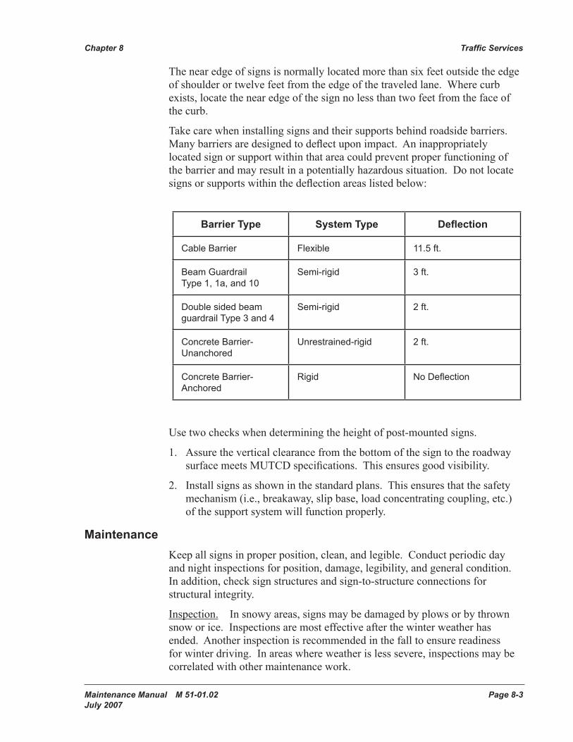
Take care when installing signs and their supports behind roadside barriers. Many barriers are designed to deflect upon impact. An inappropriately located sign or support within that area could prevent proper functioning of the barrier and may result in a potentially hazardous situation. Do not locate signs or supports within the deflection areas listed below:
Barrier Type System Type Deflection
Cable Barrier Flexible 11.5 ft.
Beam GuardrailType 1, 1a, and 10
Semi-rigid 3 ft.
Double sided beam guardrail Type 3 and 4
Semi-rigid 2 ft.
Concrete Barrier- Unanchored
Unrestrained-rigid 2 ft.
Concrete Barrier- Anchored
Rigid No Deflection
Use two checks when determining the height of post-mounted signs.
1. Assure the vertical clearance from the bottom of the sign to the roadway surface meets MUTCD specifications. This ensures good visibility.
2. Install signs as shown in the standard plans. This ensures that the safety mechanism (i.e., breakaway, slip base, load concentrating coupling, etc.) of the support system will function properly.
MaintenanceKeep all signs in proper position, clean, and legible. Conduct periodic day and night inspections for position, damage, legibility, and general condition. In addition, check sign structures and sign-to-structure connections for structural integrity.
Inspection. In snowy areas, signs may be damaged by plows or by thrown snow or ice. Inspections are most effective after the winter weather has ended. Another inspection is recommended in the fall to ensure readiness for winter driving. In areas where weather is less severe, inspections may be correlated with other maintenance work.
Traffic Services Chapter 8
Page 8-4 Maintenance Manual M 51-01.02 July 2007
Periodically check sign bridge and cantilever structure end post and metal sign post base connections. In addition, inspect sign mounting bolts and beam clips for proper tightness. Replace or secure missing or loose hand hole covers on overhead sign structure supports. Give special attention to steel sign post base and fuse plate connections. To properly function as a breakaway support while resisting wind loading, the bolt torque specified in the standard plans must be maintained.
Field Repair. Good judgment and sound economics dictate when to perform field repairs. Field repair minor sign damage whenever possible. More extensive damage normally requires sign replacement. Signs such as STOP and YIELD, whose absence can be life threatening, must receive priority replacement.
Signs that are repeatedly knocked down by vehicles may be reinstalled farther away from the roadway or at a different location along the roadway. Care must be taken to ensure that the new location meets MUTCD requirements.
Sign supports within the “clear zone” described in Chapter 2 must meet functional requirements of current safety standards. Sign support design elements are shown in the standard plans.
Never weld the steel sign post web to prevent wind blow-down. Proper fuse plate bolts and bolt torque will prevent blow-down.
Along with proper bolt torque, the area around the sign post base must be clear of obstructions that may prevent the post from slipping free of the base. Ensure that the base stub-post does not project more than 2 ½ inches above the ground. Projections above that height may snag the undercarriage of a vehicle.
Sign VisibilityPromptly remove obstructions that prevent adequate sign visibility. Vegetation trimming is sometimes necessary to ensure adequate sign visibility. Maintenance crews must be particularly careful to avoid parking equipment in front of traffic signs.
At times, highway sign faces are obscured as a result of roadway snow removal. Clear all signs as soon as possible. Regulatory and warning signs have first priority.
Sign Storage and TransportationStore signs indoors whenever possible to prevent sign sheeting failure. The signs may be packaged if dry. If packaged signs become wet, immediately unpack and separate them to allow drying.
At times, it is necessary to store signs outside. In this situation, remove the packing materials so that nothing is against the sign face. Never lay signs flat. Water accumulating between signs laying flat will cause sign sheeting failure.
Chapter 8 Traffic Services
Maintenance Manual M 51-01.02 Page 8-5 July 2007
Store signs upright on edge on blocks or other material to keep the signs off the ground. Install spacers along the sign edges to allow air circulation and normal moisture evaporation from the sign face. Avoid sign sheeting contact with treated wood. Avoid storage where dirt or water may splash on the sign face.
Transport signs on edge, face to face or back to back, to prevent sign face damage.
DelineationDelineation is defined as one, or a combination of devices, (excluding signing), that warn or provide guidance to the roadway user. These devices include pavement markings, guideposts, guardrail delineators, and barrier delineators. Delineation of environmentally sensitive areas are identified with specifically marked green guideposts.
Pavement MarkingsPavement markings are divided into two categories: long line and transverse and symbol. Long line markings are the markings that are applied parallel to the roadway. Typically long line markings are renewed with a spray application of new material applied from a striping truck. Typically transverse and symbol markings are renewed by hand, by spray, or extruded application of new material.
Long line markings include the following: center line, no-pass line, double center line, double lane line, wide lane line, double wide lane line, lane line, edge line, solid lane line, dotted extension line, wide line, wide dotted lane line, wide broken lane line, drop lane line, barrier center line, two way left turn center line, and reversible lane line.
Transverse markings include the following: Crosswalk line and stop line. Symbol markings include the following: traffic arrows, traffic letters, access parking space symbol, high occupancy vehicle (HOV) lane symbols, railroad crossing symbols, bicycle lane symbols, drainage markings, and aerial surveillance markers.
Raised pavement markers (RPMs) are installed either as positioning guides along with longitudinal markings or they are installed as a complete substitute for long line markings. Surface mounted RPMs are installed on roadways where snow removal operations use rubber blades. Recessed RPM applications consist of the installation of an RPM in a groove that has been cut into the pavement. Recessed RPM applications are allowed in areas where snow removal operations use steel blades. Various markings are identified by color code as follows:
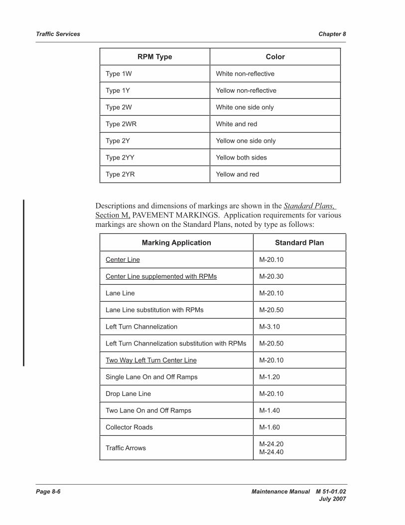
Traffic Services Chapter 8
Page 8-6 Maintenance Manual M 51-01.02 July 2007
RPM Type Color
Type 1W White non-reflective
Type 1Y Yellow non-reflective
Type 2W White one side only
Type 2WR White and red
Type 2Y Yellow one side only
Type 2YY Yellow both sides
Type 2YR Yellow and red
Descriptions and dimensions of markings are shown in the Standard Plans, Section M, PAVEMENT MARKINGS. Application requirements for various markings are shown on the Standard Plans, noted by type as follows:
Marking Application Standard Plan
Center Line M-20.10
Center Line supplemented with RPMs M-20.30
Lane Line M-20.10
Lane Line substitution with RPMs M-20.50
Left Turn Channelization M-3.10
Left Turn Channelization substitution with RPMs M-20.50
Two Way Left Turn Center Line M-20.10
Single Lane On and Off Ramps M-1.20
Drop Lane Line M-20.10
Two Lane On and Off Ramps M-1.40
Collector Roads M-1.60
Traffic Arrows M-24.20 M-24.40
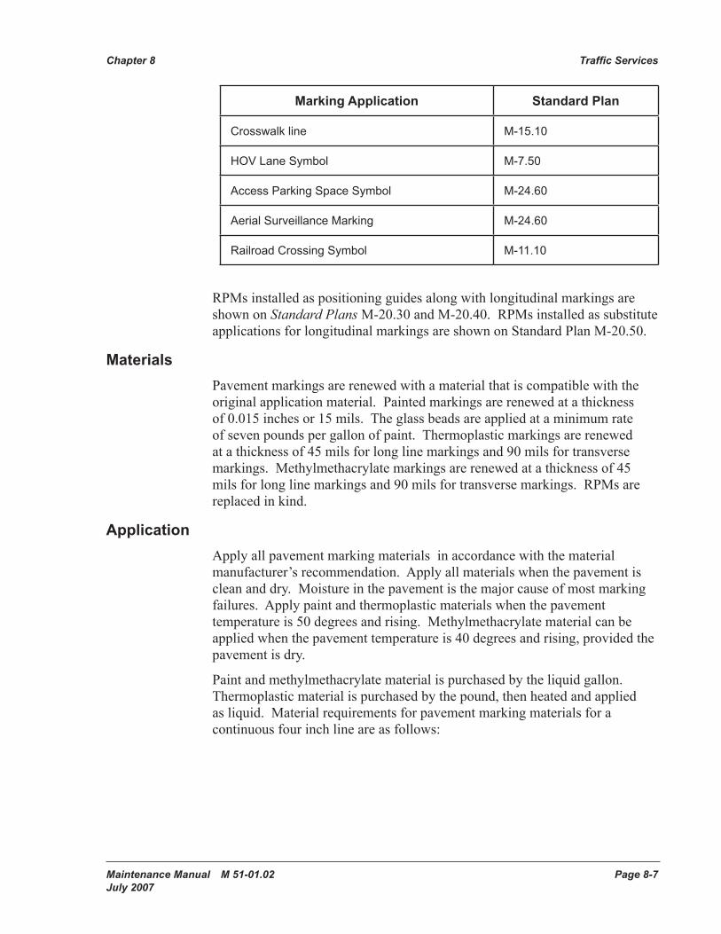
Chapter 8 Traffic Services
Maintenance Manual M 51-01.02 Page 8-7 July 2007
Marking Application Standard Plan
Crosswalk line M-15.10
HOV Lane Symbol M-7.50
Access Parking Space Symbol M-24.60
Aerial Surveillance Marking M-24.60
Railroad Crossing Symbol M-11.10
RPMs installed as positioning guides along with longitudinal markings are shown on Standard Plans M-20.30 and M-20.40. RPMs installed as substitute applications for longitudinal markings are shown on Standard Plan M-20.50.
MaterialsPavement markings are renewed with a material that is compatible with the original application material. Painted markings are renewed at a thickness of 0.015 inches or 15 mils. The glass beads are applied at a minimum rate of seven pounds per gallon of paint. Thermoplastic markings are renewed at a thickness of 45 mils for long line markings and 90 mils for transverse markings. Methylmethacrylate markings are renewed at a thickness of 45 mils for long line markings and 90 mils for transverse markings. RPMs are replaced in kind.
ApplicationApply all pavement marking materials in accordance with the material manufacturer’s recommendation. Apply all materials when the pavement is clean and dry. Moisture in the pavement is the major cause of most marking failures. Apply paint and thermoplastic materials when the pavement temperature is 50 degrees and rising. Methylmethacrylate material can be applied when the pavement temperature is 40 degrees and rising, provided the pavement is dry.
Paint and methylmethacrylate material is purchased by the liquid gallon. Thermoplastic material is purchased by the pound, then heated and applied as liquid. Material requirements for pavement marking materials for a continuous four inch line are as follows:
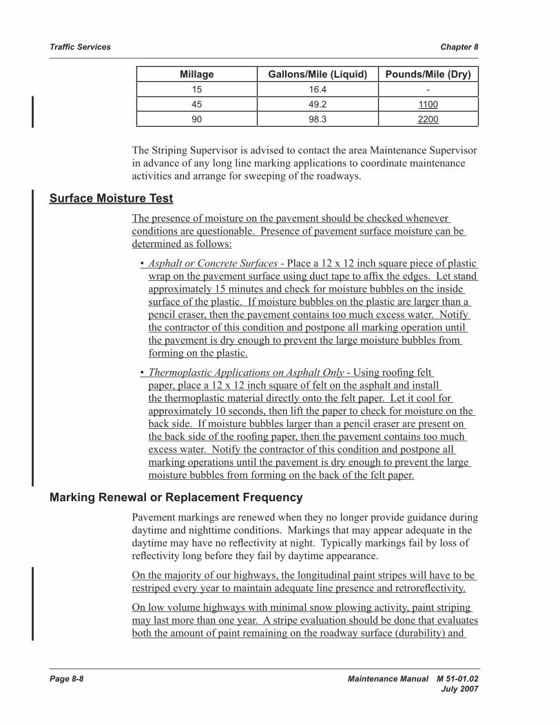
Traffic Services Chapter 8
Page 8-8 Maintenance Manual M 51-01.02 July 2007
Millage Gallons/Mile (Liquid) Pounds/Mile (Dry)15 16.4 -45 49.2 110090 98.3 2200
The Striping Supervisor is advised to contact the area Maintenance Supervisor in advance of any long line marking applications to coordinate maintenance activities and arrange for sweeping of the roadways.
Surface Moisture TestThe presence of moisture on the pavement should be checked whenever conditions are questionable. Presence of pavement surface moisture can be determined as follows:
• Asphalt or Concrete Surfaces - Place a 12 x 12 inch square piece of plastic wrap on the pavement surface using duct tape to affix the edges. Let stand approximately 15 minutes and check for moisture bubbles on the inside surface of the plastic. If moisture bubbles on the plastic are larger than a pencil eraser, then the pavement contains too much excess water. Notify the contractor of this condition and postpone all marking operation until the pavement is dry enough to prevent the large moisture bubbles from forming on the plastic.
• Thermoplastic Applications on Asphalt Only - Using roofing felt paper, place a 12 x 12 inch square of felt on the asphalt and install the thermoplastic material directly onto the felt paper. Let it cool for approximately 10 seconds, then lift the paper to check for moisture on the back side. If moisture bubbles larger than a pencil eraser are present on the back side of the roofing paper, then the pavement contains too much excess water. Notify the contractor of this condition and postpone all marking operations until the pavement is dry enough to prevent the large moisture bubbles from forming on the back of the felt paper.
Marking Renewal or Replacement FrequencyPavement markings are renewed when they no longer provide guidance during daytime and nighttime conditions. Markings that may appear adequate in the daytime may have no reflectivity at night. Typically markings fail by loss of reflectivity long before they fail by daytime appearance.
On the majority of our highways, the longitudinal paint stripes will have to be restriped every year to maintain adequate line presence and retroreflectivity.
On low volume highways with minimal snow plowing activity, paint striping may last more than one year. A stripe evaluation should be done that evaluates both the amount of paint remaining on the roadway surface (durability) and
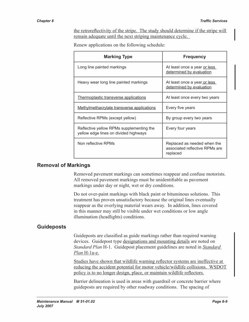
Chapter 8 Traffic Services
Maintenance Manual M 51-01.02 Page 8-9 July 2007
the retroreflectivity of the stripe. The study should determine if the stripe will remain adequate until the next striping maintenance cycle.
Renew applications on the following schedule:
Marking Type Frequency
Long line painted markings At least once a year or less determined by evaluation
Heavy wear long line painted markings At least once a year or less determined by evaluation
Thermoplastic transverse applications At least once every two years
Methylmethacrylate transverse applications Every five years
Reflective RPMs (except yellow) By group every two years
Reflective yellow RPMs supplementing the yellow edge lines on divided highways
Every four years
Non reflective RPMs Replaced as needed when the associated reflective RPMs are replaced
Removal of MarkingsRemoved pavement markings can sometimes reappear and confuse motorists. All removed pavement markings must be unidentifiable as pavement markings under day or night, wet or dry conditions.
Do not over-paint markings with black paint or bituminous solutions. This treatment has proven unsatisfactory because the original lines eventually reappear as the overlying material wears away. In addition, lines covered in this manner may still be visible under wet conditions or low angle illumination (headlights) conditions.
GuidepostsGuideposts are classified as guide markings rather than required warning devices. Guidepost type designations and mounting details are noted on Standard Plan H-1. Guidepost placement guidelines are noted in Standard Plan H-1a-e.
Studies have shown that wildlife warning reflector systems are ineffective at reducing the accident potential for motor vehicle/wildlife collisions. WSDOT policy is to no longer design, place, or maintain wildlife reflectors.
Barrier delineation is used in areas with guardrail or concrete barrier where guideposts are required by other roadway conditions. The spacing of
Traffic Services Chapter 8
Page 8-10 Maintenance Manual M 51-01.02 July 2007
barrier delineators for these applications is the same as the spacing noted for guideposts. Promptly replace damaged or missing guideposts and barrier delineators.
Traffic Barriers and Impact AttenuatorsTraffic barriers, such as beam guardrail, cable barrier, and concrete barrier are used to protect vehicles from hazards within the Design Clear Zone (as defined in Chapter 2) that cannot be removed or otherwise relocated. Hazards may be a single point, such as a bridge pier, or an extensive area, such as steep embankments. Elements of traffic barriers include the standard run of barrier, terminals or anchors for the treatment of the ends, and transitions for connecting to stiffer barriers.
Maintain records with descriptions of observations and repairs.
MaintenanceBarriers must be properly maintained to ensure that they will perform properly when struck by errant vehicles. Keep the area under and around barriers clean and free of vegetation and debris. Do not allow objects that could become projectiles to be placed on top of barriers.
InspectionInspect barriers periodically, either by visual drive-by or by physical inspections.
Inspect for:
• The overall condition of the barrier.
• Proper interconnection of units.
• Proper installation of anchor cables and connecting pins.
• Tightness of blocks and fasteners.
• Proper overlapping of beam guardrail.
• Secure attachment of beam guardrail.
RepairRepair damaged roadside barriers promptly. A response within two weeks is desired unless higher priorities preempt action. Once a damaged barrier has been identified, determine if the barriers will be repaired, replaced, or removed.
Removal of a barrier may be the best solution, but this requires an evaluation of the requirement for a barrier. In some instances the need for the barrier can be eliminated (by flattening slopes or removal of a fixed object for
Chapter 8 Traffic Services
Maintenance Manual M 51-01.02 Page 8-11 July 2007
example). Contact the Region Traffic Engineer for guidance on evaluating the requirement for a barrier. The following guidance is provided for evaluating the requirement to upgrade a barrier:
Standard Run of BarrierThe standard run of barrier is the majority of the barrier run. It includes all of the barrier except the terminals and transition sections. Barriers have evolved over many years and as a result there are systems on Washington State highways that no longer meet current design standards.
Examples of non-standard barriers include:
• W-beam guardrail with 12’-6” post spacing and no block outs.
• W-beam guardrail on concrete posts.
• Cable barrier on wood or concrete posts.
• Half moon or C shape rail element.
If damage to these barriers requires the reconstruction of a significant portion of the run, consider upgrading the entire run to current standards. For minor repairs, upgrade the damaged portion of w-beam barriers to current standards (post spacing, block outs, etc.). Minor repairs to non-standard cable, half moon, or C shaped rails can be repaired in kind as upgrading may not be practical.
Terminals and AnchorsA guardrail anchor is required at the ends of a standard run of guardrail to develop its tensile strength throughout its length. In addition, when the end of any barrier is subject to head-on impacts, a crash worthy terminal is required. Guardrail anchorage may be provided as part of the terminal, as a connection to a rigid structure, or by an anchor whose only purpose is to strengthen the run (Type 4 and 7 anchors).
Many different terminal designs have been used on Washington State highways. Upgrade damaged guardrail ends that do not have a crash worthy design.
Common features of non-crash worthy designs are as follows:
• No cable anchor.
• A cable anchored into concrete in front of the first post.
• Second post not breakaway (CRT).
• Design A end section (Design C end sections are acceptable to be left in place).
• Beam guardrail on both sides of the posts (two sided).
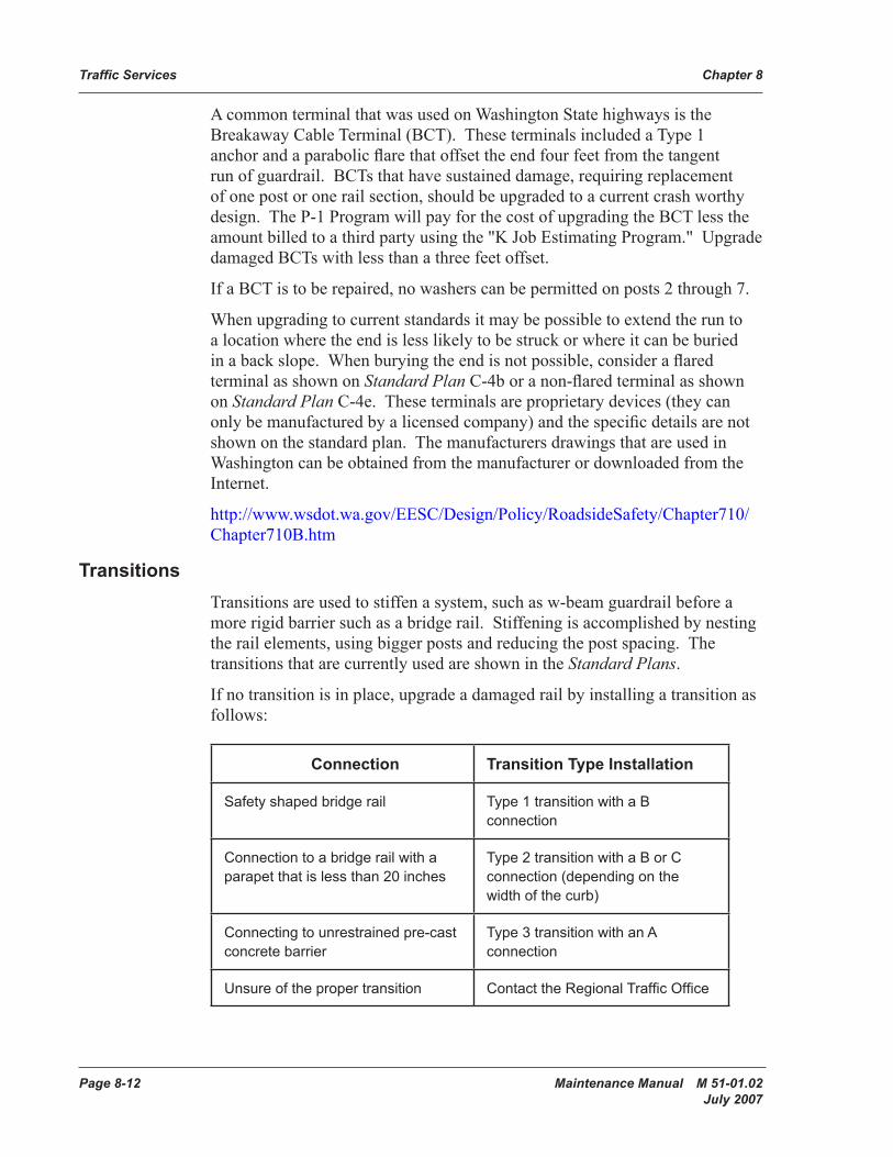
Traffic Services Chapter 8
Page 8-12 Maintenance Manual M 51-01.02 July 2007
A common terminal that was used on Washington State highways is the Breakaway Cable Terminal (BCT). These terminals included a Type 1 anchor and a parabolic flare that offset the end four feet from the tangent run of guardrail. BCTs that have sustained damage, requiring replacement of one post or one rail section, should be upgraded to a current crash worthy design. The P-1 Program will pay for the cost of upgrading the BCT less the amount billed to a third party using the "K Job Estimating Program." Upgrade damaged BCTs with less than a three feet offset.
If a BCT is to be repaired, no washers can be permitted on posts 2 through 7.
When upgrading to current standards it may be possible to extend the run to a location where the end is less likely to be struck or where it can be buried in a back slope. When burying the end is not possible, consider a flared terminal as shown on Standard Plan C-4b or a non-flared terminal as shown on Standard Plan C-4e. These terminals are proprietary devices (they can only be manufactured by a licensed company) and the specific details are not shown on the standard plan. The manufacturers drawings that are used in Washington can be obtained from the manufacturer or downloaded from the Internet.
http://www.wsdot.wa.gov/EESC/Design/Policy/RoadsideSafety/Chapter710/ Chapter710B.htm
TransitionsTransitions are used to stiffen a system, such as w-beam guardrail before a more rigid barrier such as a bridge rail. Stiffening is accomplished by nesting the rail elements, using bigger posts and reducing the post spacing. The transitions that are currently used are shown in the Standard Plans.
If no transition is in place, upgrade a damaged rail by installing a transition as follows:
Connection Transition Type Installation
Safety shaped bridge rail Type 1 transition with a B connection
Connection to a bridge rail with a parapet that is less than 20 inches
Type 2 transition with a B or C connection (depending on the width of the curb)
Connecting to unrestrained pre-cast concrete barrier
Type 3 transition with an A connection
Unsure of the proper transition Contact the Regional Traffic Office
Chapter 8 Traffic Services
Maintenance Manual M 51-01.02 Page 8-13 July 2007
Sometimes damage to a transition is minor, not requiring the replacement of all of the posts. In these situations, existing transitions that have a w-beam rail element can be upgraded by adding an additional (nested) rail element. Upgrading the connection is not required for minor repairs.
Impact AttenuatorsImpact attenuators can be used as an end treatment for barriers or to prevent errant vehicles from impacting other fixed objects. Keep records of impact attenuators in use: brand, an illustrated layout showing parts order numbers, module locations and weights, and a photograph of the installation.
MaintenanceReplace and repair impact attenuators in accordance with the manufacturer’s recommendations. Check for proper restraining cable tightness, anchor bolt tightness, diaphragm and hardware in good condition, and fender panels securely in place.
Inspect sand-filled barrels to ensure lids are firmly in place and not dented. Make sure there is no moisture inside the modules, no damage or visible cracks in the outer shell. Check that each barrel is filled with the correct amount of dry sand or dry pea gravel. (See manufacturer’s specifications.)
If the sand is found to contain moisture, mix salt with the sand at a rate of 10 percent to 20 percent (by volume) to prevent freezing. Some sand may need to be discarded before adding the salt to prevent overfilling the barrel.
Replace damaged water cell units. If one is to be left in place, check for leakage.
IslandsIslands must be properly maintained to provide protection of motorists and pedestrians. Keep island passageways clear of debris. Repaint outlines of islands as directed by the Regional Traffic Engineer. Replace missing or damaged raised pavement markers when more than three consecutive markers are missing.
Displaced or missing raised curb must be repositioned or replaced. Paint raised curb as directed by the Regional Traffic Engineer.
Transit Vehicle Stop Zones
Maintenance
Transit stops along state highways outside cities are maintained by the state. These locations should be kept free of debris, potholes and other obstacles that could cause tripping. The responsibility for maintaining transit stops on state highways inside cities is covered in the agreement discussed in the Traffic Manual’s transit vehicle stop zone guidelines. An inventory of transit stops is available at the Regional Traffic Office.
Traffic Services Chapter 8
Page 8-14 Maintenance Manual M 51-01.02 July 2007