Embed Size (px)
Citation preview
Pull-out behaviour of blind boltsfrom concrete-filled tubes&1 Yusak Oktavianus Msc (Eng)
PhD candidate, Department of Infrastructure Engineering, University ofMelbourne, Melbourne, Australia
&2 Huang Yao PhDManaging Director, Australia Xing One Pty Ltd, Lidcombe, Australia
&3 Helen M. Goldsworthy PhDAssociate Professor, Department of Infrastructure Engineering,University of Melbourne, Melbourne, Australia
&4 Emad F. Gad PhDProfessor, Chair of Civil and Construction Engineering, Faculty ofScience, Engineering and Technology, Swinburne University ofTechnology, Hawthorn, Australia
1 2 3 4
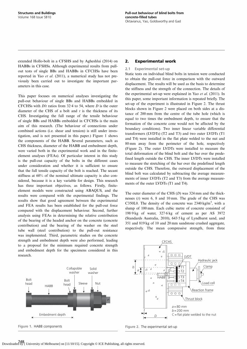
The use of concrete-filled steel circular hollow sections as columns is becoming more popular because of their superior
capacity, good ductility and large energy absorption capacity. The utilisation of blind bolts, which can be installed
from the outside of the column, is possible and has been the subject of considerable research. Results from pull-out
testing of blind bolts and the headed anchor blind bolt, which is a modification of the original blind bolt, are reported
in this paper. The tests were performed to establish the behaviour of individual bolts. Results from the research will
ultimately be used in the design of moment-resisting connections using these bolts. The effect of varying several
parameters such as the tube thickness, bolt diameter and embedment depth were investigated both experimentally
and by way of numerical models using finite-element analysis. After achieving a good agreement between the
experimental and numerical results, further analysis was implemented to determine the relative contributions of the
concrete and tube wall to the pull-out resistance. Parametric studies on concrete strength and embedment depth were
also performed.
1. IntroductionThe use of concrete-filled (CF) circular hollow sections (CHSs)as columns is becoming more popular because of theirsuperior capacity, good ductility and large energy absorptioncapacity under seismic action (Han and Li, 2010). The con-crete infill assists the CHS in resisting buckling, and the CHSprovides confinement for the concrete. Other benefits of theuse of CFCHS columns are fast construction, as they do notneed additional formwork, and aesthetic appeal.
Conventional bolts cannot be used to connect to a CHSbecause of lack of access to the inside of the section. Thisproblem has led to the development of blind bolts, which canbe installed from the outside of the CHS. The commerciallyavailable blind bolts include the Huck high-strength blindbolt (Huck International, 1990), the Lindapter Hollo-bolt(Lindapter International, 1995), flow drilling (France et al.,1999) and the Ajax Oneside (Ajax Engineered Fasteners,2002). There are different types of blind bolts on the market,and this paper focuses on one type, to demonstrate the
mechanical behaviour of a system rather than the performanceof a specific blind bolt. The Ajax Oneside blind bolt was usedin this research, and is referred to throughout this paperas ‘BB’.
Research on BB connections to unfilled Square hollow section(SHS) columns was carried out by Lee et al. (2010, 2011a,2011b). Taking advantage of the concrete infill, the BB can bemodified either using a cogged anchor (CABB) (Yao et al.,2008) or headed anchor (HABB) (Yao et al., 2011). An exper-imental and numerical investigation of the pull-out behaviourof CABBs in CFCHSs has been reported in Yao et al. (2008).Although the CABBs provided good strength and stiffness,HABBs are considered to be more practical than CABBsbecause HABBs can be easily manufactured in one piece.Furthermore, disorientation of the cogged anchor, which some-times occurred during the installation of the CABBs, did notoccur if HABBs were being used. A similar concept utilisingadditional embedment depth has also been investigated byMahmood et al. (2014) and Pitrakkos and Tizani (2013) on an
747
Structures and BuildingsVolume 168 Issue SB10
Pull-out behaviour of blind bolts fromconcrete-filled tubesOktavianus, Yao, Goldsworthy and Gad
Proceedings of the Institution of Civil EngineersStructures and Buildings 168 October 2015 Issue SB10Pages 747–759 http://dx.doi.org/10.1680/stbu.14.00098Paper 1400098Received 03/10/2014 Accepted 26/02/2015Published online 20/07/2015Keywords: anchors & anchorages/composite structures/engineering mechanics
ICE Publishing: All rights reserved
Downloaded by [ University of Melbourne] on [11/10/15]. Copyright © ICE Publishing, all rights reserved.
extended Hollo-bolt in a CFSHS and by Agheshlui (2014) onHABBs in CFSHSs. Although experimental results from pull-out tests of single BBs and HABBs in CFCHSs have beenreported in Yao et al. (2011), a numerical study has not pre-viously been carried out to investigate the important par-ameters in this case.
This paper focuses on numerical analyses investigating thepull-out behaviour of single BBs and HABBs embedded inCFCHSs with D/t ratios from 32·4 to 54, where D is the outerdiameter of the CHS of a bolt and t is the thickness of itsCHS. Investigating the full range of the tensile behaviourof single BBs and HABBs embedded in CFCHSs is the mainaim of this research. (The behaviour of connections undercombined actions (i.e. shear and tension) is still under inves-tigation, and is not presented in this paper.) Figure 1 showsthe components of the HABB. Several parameters, such asCHS thickness, diameter of the HABB and embedment depth,were varied both in the experimental work and in the finite-element analyses (FEAs). Of particular interest in this studyis the pull-out capacity of the bolts in the different casesunder consideration and whether it is sufficient to ensurethat the full tensile capacity of the bolt is reached. The secantstiffness at 60% of the nominal ultimate capacity is also con-sidered, because it is a key variable for design. This researchhas three important objectives, as follows. Firstly, finite-element models were constructed using ABAQUS, and theresults were compared with the experimental findings. Theresults show that good agreement between the experimentaland FEA results has been established for the pull-out forcecompared with the displacement behaviour. Second, furtheranalysis using FEAs in determining the relative contributionof the bearing of the headed anchor on the concrete (concretecontribution) and the bearing of the washer on the steeltube wall (steel contribution) to the pull-out resistancewas implemented. Third, parametric studies on the concretestrength and embedment depth were also performed, leadingto a proposal for the minimum required concrete strengthand embedment depth for the specimens considered in thisresearch.
2. Experimental work
2.1 Experimental set-upStatic tests on individual blind bolts in tension were conductedto obtain the pull-out force in comparison with the outwarddisplacement. The results will be used as the basis to determinethe stiffness and the strength of the connection. The details ofthe experimental set-up were explained in Yao et al. (2011). Inthis paper, some important information is repeated briefly. Theset-up of the experiment is illustrated in Figure 2. The thrustblocks shown in Figure 2 were placed on both sides at a dis-tance of 200 mm from the centre of the tube hole (which isequal to two times the embedment depth, to ensure that theformation of the concrete cone would not be affected by theboundary conditions). Two inner linear variable differentialtransformers (LVDTs) (T2 and T3) and two outer LVDTs (T1and T4) were installed in the flat plate welded to the nut and80mm away from the perimeter of the hole, respectively(Figure 2). The outer LVDTs were installed to measure thetotal deformation of the blind bolt and the bar over the prede-fined length outside the CHS. The inner LVDTs were installedto measure the stretching of the bar over the predefined lengthoutside the CHS. Therefore, the outward displacement of theblind bolt was calculated by subtracting the average measure-ments of inner LVDTs (T2 and T3) from the average measure-ments of the outer LVDTs (T1 and T4).
The outer diameter of the CHS (D) was 324 mm and the thick-nesses (t) were 6, 8 and 10mm. The grade of the CHS wasC350L0. The density of the concrete was 2340 kg/m3, with aslump of 100 mm. Each cubic metre of concrete consisted of198·9 kg of water, 327·6 kg of cement as per AS 3972(Standards Australia, 2010), 643·5 kg of Lyndhurst sand, and351 and 819 kg of 10 and 20mm sandstone crushed aggregate,respectively. The mean compressive strength, from three
Collapsiblewasher
Bolthead
Bolthead Sleeve Nut
Embedment depth
HABB
Solidwasher
Figure 1. HABB components
CFCHS
LVDT
HABB
Cb
aT1T2
T3T4
Hydraulic jack
Clamp
Load cell
Reaction frame
Thrust block
D
t b = 200 mma = 80 mm
C = flat plate welded to the nut
Figure 2. The experimental set-up
748
Structures and BuildingsVolume 168 Issue SB10
Pull-out behaviour of blind bolts fromconcrete-filled tubesOktavianus, Yao, Goldsworthy and Gad
Downloaded by [ University of Melbourne] on [11/10/15]. Copyright © ICE Publishing, all rights reserved.
cylinder tests of concrete, was 48MPa. The BB and HABBwere grade 8·8. The BB material properties and other detailscan be found in an Ajax technical note (Fernando, 2005). Thedetails of the specimens used in the experiment are shown inTable 1. The notation used is as follows: ‘T6’ denotes a speci-men with a tube thickness of 6 mm, ‘D16’ denotes a specimenwith a blind bolt diameter of 16 mm, ‘N1’ indicates a normalblind bolt (i.e. a BB), ‘N2’ indicates a HABB with an embed-ment depth of 100mm, and ‘E’ indicates experimental work.The embedment depth in this paper is measured along theblind bolt from the beginning of the first head to the beginningof the second head, as shown in Figure 1. A rounded nut wasused as the head, and both the first and second heads have thesame thickness. Therefore, the effective embedment depth willbe equal to the sum of the embedment depth and the thicknessof the washer. The bolts were tightened to a ‘snug tight’ con-dition, defined as the tightness achieved with a few impacts ofan impact wrench or by the full effort of a person using a stan-dard podger spanner (Standards Australia, 1998). The purposeof ‘snug tight’ is to bring the connected plies into firm contact(AISC, 2010).
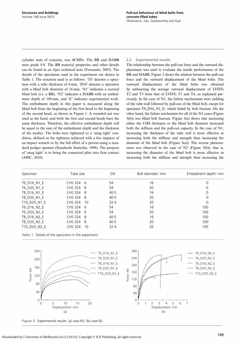
2.2 Experimental resultsThe relationship between the pull-out force and the outward dis-placement was used to evaluate the tensile performance of theBB and HABB. Figure 3 shows the relation between the pull-outforce and the outward displacement of the blind bolts. Theoutward displacement of the blind bolts was obtainedby subtracting the average outward displacement of LVDTsT2 and T3 from that of LVDTs T1 and T4, as explained pre-viously. In the case of N1, the failure mechanisms were yieldingof the tube wall followed by pull-out of the blind bolt, except forspecimen T8_D16_N1_E, which failed by bolt fracture. On theother hand, the failure mechanism for all of the N2 cases (Figure3(b)) was blind bolt fracture. Figure 3(a) shows that increasingeither the CHS thickness or the blind bolt diameter increasedboth the stiffness and the pull-out capacity. In the case of N1,increasing the thickness of the tube wall is more effective inincreasing both the stiffness and strength than increasing thediameter of the blind bolt (Figure 3(a)). The reverse phenom-enon was observed in the case of N2 (Figure 3(b)): that is,increasing the diameter of the blind bolt is more effective inincreasing both the stiffness and strength than increasing the
240
200
160
120
Forc
e: k
N
80
40
00 0 1 2 3 4 5 6 75
Displacement: mm(a) (b)
Displacement: mm10 15 20
240
280T6_D16_N1_E
T6_D20_N1_E
T8_D16_N1_ET8_D20_N1_E
T10_D20_N1_E
T6_D16_N2_E
T6_D20_N2_E
T8_D16_N2_ET8_D20_N2_E
T10_D20_N2_E
200
160
120Forc
e: k
N
80
40
0
Figure 3. Experimental results: (a) case N1; (b) case N2
Specimen Tube size D/t Bolt diameter: mm Embedment depth: mm
T6_D16_N1_E CHS 324�6 54 16 0T6_D20_N1_E CHS 324�6 54 20 0T8_D16_N1_E CHS 324�8 40·5 16 0T8_D20_N1_E CHS 324�8 40·5 20 0T10_D20_N1_E CHS 324�10 32·4 20 0T6_D16_N2_E CHS 324�6 54 16 100T6_D20_N2_E CHS 324�6 54 20 100T8_D16_N2_E CHS 324�8 40·5 16 100T8_D20_N2_E CHS 324�8 40·5 20 100T10_D20_N2_E CHS 324�10 32·4 20 100
Table 1. Details of the specimens in the experiment
749
Structures and BuildingsVolume 168 Issue SB10
Pull-out behaviour of blind bolts fromconcrete-filled tubesOktavianus, Yao, Goldsworthy and Gad
Downloaded by [ University of Melbourne] on [11/10/15]. Copyright © ICE Publishing, all rights reserved.
thickness of the tube wall. Further explanation of this behaviouris presented in subsequent sections on the results of the FEAs.
3. Finite element analysis
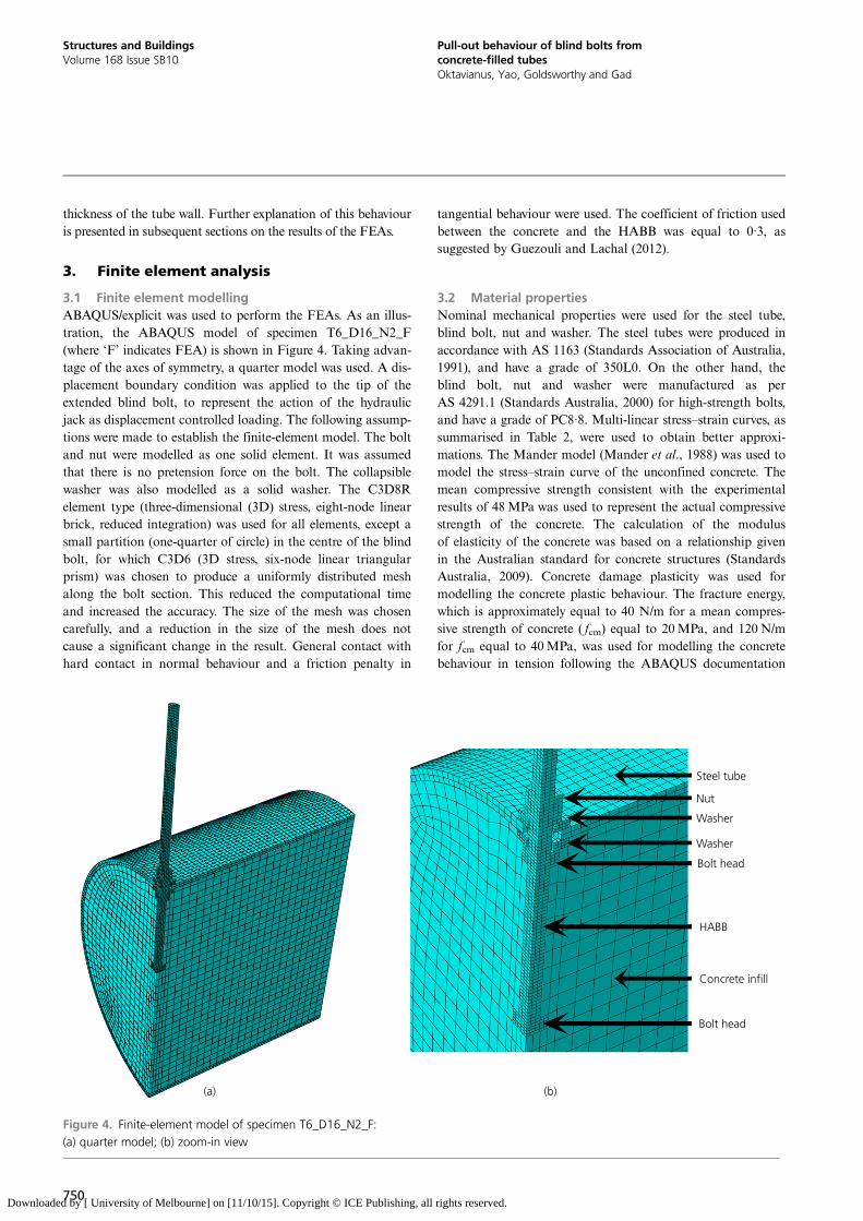
3.1 Finite element modellingABAQUS/explicit was used to perform the FEAs. As an illus-tration, the ABAQUS model of specimen T6_D16_N2_F(where ‘F’ indicates FEA) is shown in Figure 4. Taking advan-tage of the axes of symmetry, a quarter model was used. A dis-placement boundary condition was applied to the tip of theextended blind bolt, to represent the action of the hydraulicjack as displacement controlled loading. The following assump-tions were made to establish the finite-element model. The boltand nut were modelled as one solid element. It was assumedthat there is no pretension force on the bolt. The collapsiblewasher was also modelled as a solid washer. The C3D8Relement type (three-dimensional (3D) stress, eight-node linearbrick, reduced integration) was used for all elements, except asmall partition (one-quarter of circle) in the centre of the blindbolt, for which C3D6 (3D stress, six-node linear triangularprism) was chosen to produce a uniformly distributed meshalong the bolt section. This reduced the computational timeand increased the accuracy. The size of the mesh was chosencarefully, and a reduction in the size of the mesh does notcause a significant change in the result. General contact withhard contact in normal behaviour and a friction penalty in
tangential behaviour were used. The coefficient of friction usedbetween the concrete and the HABB was equal to 0·3, assuggested by Guezouli and Lachal (2012).
3.2 Material propertiesNominal mechanical properties were used for the steel tube,blind bolt, nut and washer. The steel tubes were produced inaccordance with AS 1163 (Standards Association of Australia,1991), and have a grade of 350L0. On the other hand, theblind bolt, nut and washer were manufactured as perAS 4291.1 (Standards Australia, 2000) for high-strength bolts,and have a grade of PC8·8. Multi-linear stress–strain curves, assummarised in Table 2, were used to obtain better approxi-mations. The Mander model (Mander et al., 1988) was used tomodel the stress–strain curve of the unconfined concrete. Themean compressive strength consistent with the experimentalresults of 48MPa was used to represent the actual compressivestrength of the concrete. The calculation of the modulusof elasticity of the concrete was based on a relationship givenin the Australian standard for concrete structures (StandardsAustralia, 2009). Concrete damage plasticity was used formodelling the concrete plastic behaviour. The fracture energy,which is approximately equal to 40 N/m for a mean compres-sive strength of concrete ( fcm) equal to 20MPa, and 120 N/mfor fcm equal to 40MPa, was used for modelling the concretebehaviour in tension following the ABAQUS documentation
Steel tube
Nut
Washer
Washer
Bolt head
Bolt head
(a)
HABB
Concrete infill
(b)
Figure 4. Finite-element model of specimen T6_D16_N2_F:(a) quarter model; (b) zoom-in view
750
Structures and BuildingsVolume 168 Issue SB10
Pull-out behaviour of blind bolts fromconcrete-filled tubesOktavianus, Yao, Goldsworthy and Gad
Downloaded by [ University of Melbourne] on [11/10/15]. Copyright © ICE Publishing, all rights reserved.
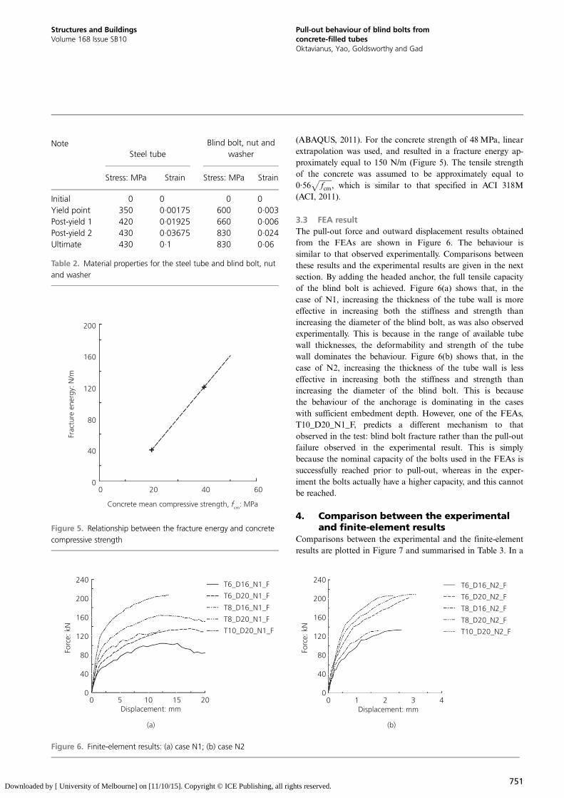
(ABAQUS, 2011). For the concrete strength of 48MPa, linearextrapolation was used, and resulted in a fracture energy ap-proximately equal to 150 N/m (Figure 5). The tensile strengthof the concrete was assumed to be approximately equal to0·56
ffiffiffiffiffiffiffifcm
p, which is similar to that specified in ACI 318M
(ACI, 2011).
3.3 FEA resultThe pull-out force and outward displacement results obtainedfrom the FEAs are shown in Figure 6. The behaviour issimilar to that observed experimentally. Comparisons betweenthese results and the experimental results are given in the nextsection. By adding the headed anchor, the full tensile capacityof the blind bolt is achieved. Figure 6(a) shows that, in thecase of N1, increasing the thickness of the tube wall is moreeffective in increasing both the stiffness and strength thanincreasing the diameter of the blind bolt, as was also observedexperimentally. This is because in the range of available tubewall thicknesses, the deformability and strength of the tubewall dominates the behaviour. Figure 6(b) shows that, in thecase of N2, increasing the thickness of the tube wall is lesseffective in increasing both the stiffness and strength thanincreasing the diameter of the blind bolt. This is becausethe behaviour of the anchorage is dominating in the caseswith sufficient embedment depth. However, one of the FEAs,T10_D20_N1_F, predicts a different mechanism to thatobserved in the test: blind bolt fracture rather than the pull-outfailure observed in the experimental result. This is simplybecause the nominal capacity of the bolts used in the FEAs issuccessfully reached prior to pull-out, whereas in the exper-iment the bolts actually have a higher capacity, and this cannotbe reached.
4. Comparison between the experimentaland finite-element results
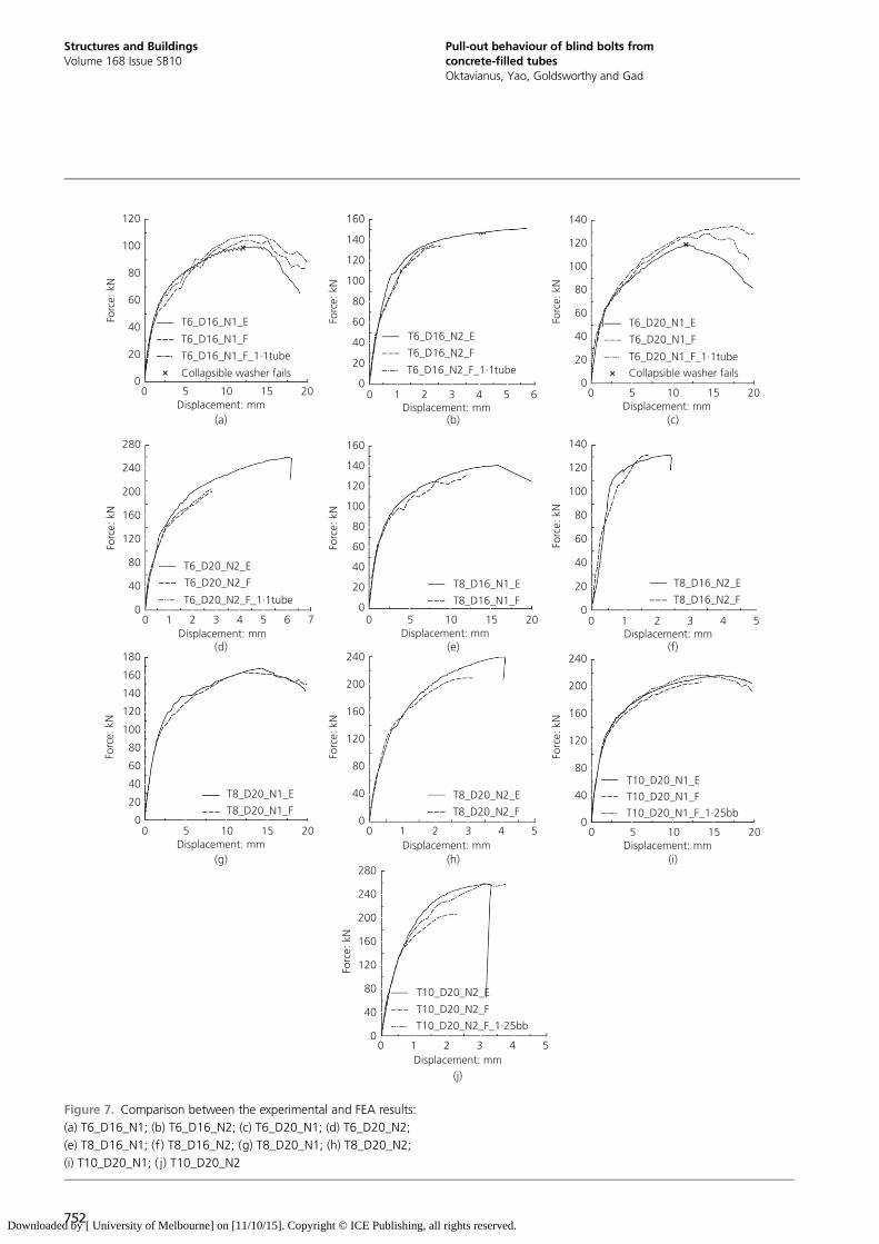
Comparisons between the experimental and the finite-elementresults are plotted in Figure 7 and summarised in Table 3. In a
200
160
120
80
Frac
ture
ene
rgy:
N/m
Concrete mean compressive strength, fcm: MPa
40
00 20 40 60
Figure 5. Relationship between the fracture energy and concretecompressive strength
240
200
160
120
80
40
00 0 1 2 3 45 10 15 20
240
200
160
120
80
40
0
T6_D16_N1_F
T6_D20_N1_F
T8_D16_N1_F
T8_D20_N1_F
T10_D20_N1_F
T6_D16_N2_F
T6_D20_N2_F
T8_D16_N2_F
T8_D20_N2_F
T10_D20_N2_F
Forc
e: k
N
Forc
e: k
N
Displacement: mm
(a) (b)
Displacement: mm
Figure 6. Finite-element results: (a) case N1; (b) case N2
NoteSteel tube
Blind bolt, nut andwasher
Stress: MPa Strain Stress: MPa Strain
Initial 0 0 0 0Yield point 350 0·00175 600 0·003Post-yield 1 420 0·01925 660 0·006Post-yield 2 430 0·03675 830 0·024Ultimate 430 0·1 830 0·06
Table 2. Material properties for the steel tube and blind bolt, nutand washer
751
Structures and BuildingsVolume 168 Issue SB10
Pull-out behaviour of blind bolts fromconcrete-filled tubesOktavianus, Yao, Goldsworthy and Gad
Downloaded by [ University of Melbourne] on [11/10/15]. Copyright © ICE Publishing, all rights reserved.
120
100
80
60
Forc
e: k
N
Forc
e: k
N
Forc
e: k
N
40
20
0
280
240
200
160
120
80
40
0
240
200
160
120
80
40
0
240
200
160
120
80
40
0
120
140
160
100
80
60
40
20
0
Forc
e: k
N
Forc
e: k
N
Forc
e: k
N
120
140
160
180
100
80
60
40
20
0
Forc
e: k
N
Forc
e: k
N
280
240
200
160
120
80
40
0
Forc
e: k
N
120
140
160
100
80
60
40
20
0
120
140
100
80
60
40
20
0
Forc
e: k
N
120
140
100
80
60
40
20
0
0 1 2 3Displacement: mm Displacement: mmDisplacement: mm
(a) (b) (c)
(d) (e) (f)
(g) (h) (i)
(j)
4 5
0 1 2 3Displacement: mm
4 5
0 1 2 3Displacement: mm
4 5
0 1 2 3Displacement: mm
4 5
0 1 2 3Displacement: mm
4 5 6 7
60 5 10 15 20 0 5 10 15 20
Displacement: mm0 5 10 15 20
Displacement: mm0 5 10 15 20
Displacement: mm0 5 10 15 20
T6_D16_N1_E
T6_D16_N1_F
T6_D16_N1_F_1·1tube
Collapsible washer fails Collapsible washer fails
T6_D16_N2_E
T6_D16_N2_F
T8_D16_N1_E
T8_D16_N1_F
T8_D16_N2_E
T8_D16_N2_F
T8_D20_N1_E
T8_D20_N1_FT8_D20_N2_E
T8_D20_N2_F
T10_D20_N1_E
T10_D20_N1_F
T10_D20_N1_F_1·25bb
T10_D20_N2_E
T10_D20_N2_F
T10_D20_N2_F_1·25bb
T6_D16_N2_F_1·1tube
T6_D20_N1_E
T6_D20_N1_F
T6_D20_N1_F_1·1tube
T6_D20_N2_E
T6_D20_N2_F
T6_D20_N2_F_1·1tube
Figure 7. Comparison between the experimental and FEA results:(a) T6_D16_N1; (b) T6_D16_N2; (c) T6_D20_N1; (d) T6_D20_N2;(e) T8_D16_N1; (f) T8_D16_N2; (g) T8_D20_N1; (h) T8_D20_N2;(i) T10_D20_N1; ( j) T10_D20_N2
752
Structures and BuildingsVolume 168 Issue SB10
Pull-out behaviour of blind bolts fromconcrete-filled tubesOktavianus, Yao, Goldsworthy and Gad
Downloaded by [ University of Melbourne] on [11/10/15]. Copyright © ICE Publishing, all rights reserved.
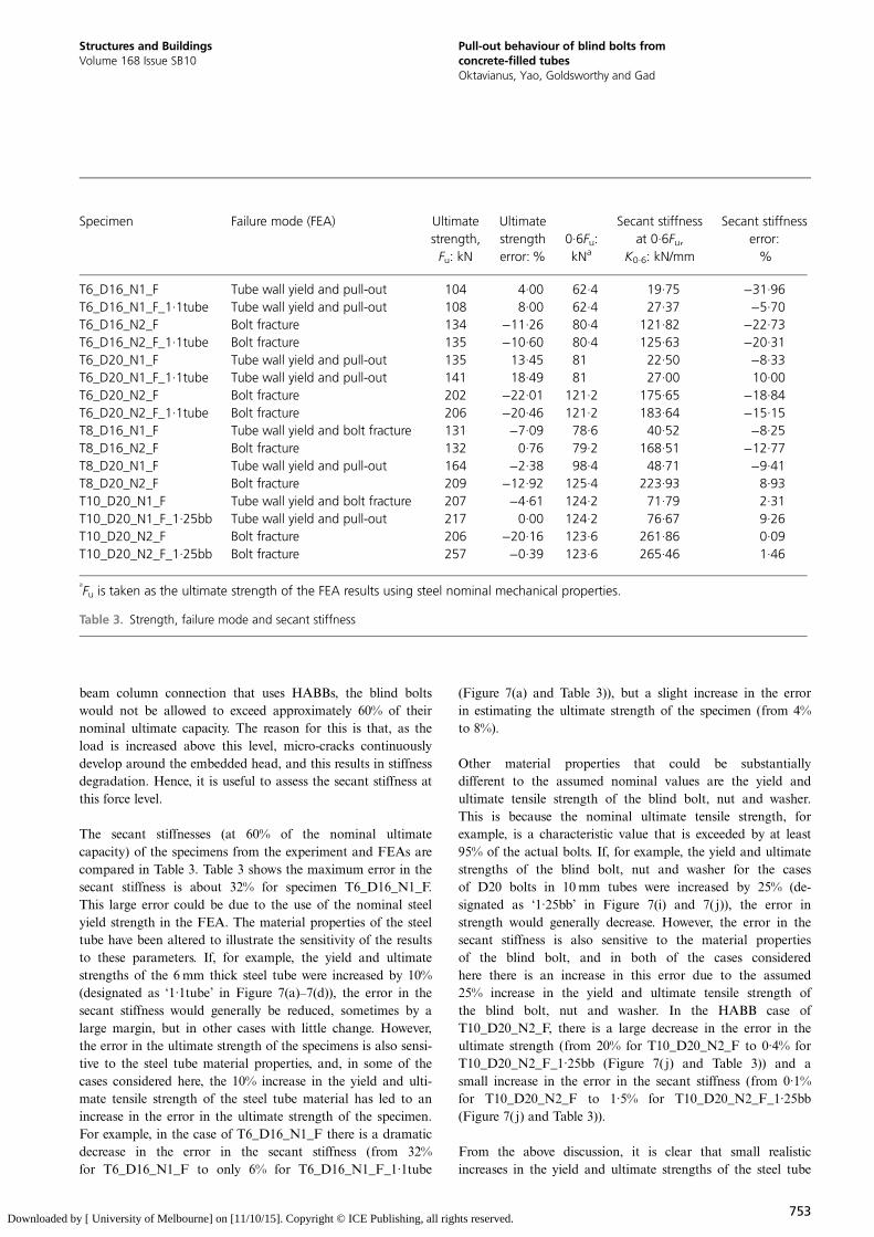
beam column connection that uses HABBs, the blind boltswould not be allowed to exceed approximately 60% of theirnominal ultimate capacity. The reason for this is that, as theload is increased above this level, micro-cracks continuouslydevelop around the embedded head, and this results in stiffnessdegradation. Hence, it is useful to assess the secant stiffness atthis force level.
The secant stiffnesses (at 60% of the nominal ultimatecapacity) of the specimens from the experiment and FEAs arecompared in Table 3. Table 3 shows the maximum error in thesecant stiffness is about 32% for specimen T6_D16_N1_F.This large error could be due to the use of the nominal steelyield strength in the FEA. The material properties of the steeltube have been altered to illustrate the sensitivity of the resultsto these parameters. If, for example, the yield and ultimatestrengths of the 6 mm thick steel tube were increased by 10%(designated as ‘1·1tube’ in Figure 7(a)–7(d)), the error in thesecant stiffness would generally be reduced, sometimes by alarge margin, but in other cases with little change. However,the error in the ultimate strength of the specimens is also sensi-tive to the steel tube material properties, and, in some of thecases considered here, the 10% increase in the yield and ulti-mate tensile strength of the steel tube material has led to anincrease in the error in the ultimate strength of the specimen.For example, in the case of T6_D16_N1_F there is a dramaticdecrease in the error in the secant stiffness (from 32%for T6_D16_N1_F to only 6% for T6_D16_N1_F_1·1tube
(Figure 7(a) and Table 3)), but a slight increase in the errorin estimating the ultimate strength of the specimen (from 4%to 8%).
Other material properties that could be substantiallydifferent to the assumed nominal values are the yield andultimate tensile strength of the blind bolt, nut and washer.This is because the nominal ultimate tensile strength, forexample, is a characteristic value that is exceeded by at least95% of the actual bolts. If, for example, the yield and ultimatestrengths of the blind bolt, nut and washer for the casesof D20 bolts in 10 mm tubes were increased by 25% (de-signated as ‘1·25bb’ in Figure 7(i) and 7( j)), the error instrength would generally decrease. However, the error in thesecant stiffness is also sensitive to the material propertiesof the blind bolt, and in both of the cases consideredhere there is an increase in this error due to the assumed25% increase in the yield and ultimate tensile strength ofthe blind bolt, nut and washer. In the HABB case ofT10_D20_N2_F, there is a large decrease in the error in theultimate strength (from 20% for T10_D20_N2_F to 0·4% forT10_D20_N2_F_1·25bb (Figure 7( j) and Table 3)) and asmall increase in the error in the secant stiffness (from 0·1%for T10_D20_N2_F to 1·5% for T10_D20_N2_F_1·25bb(Figure 7( j) and Table 3)).
From the above discussion, it is clear that small realisticincreases in the yield and ultimate strengths of the steel tube
Specimen Failure mode (FEA) Ultimatestrength,Fu: kN
Ultimatestrengtherror:%
0·6Fu:kNa
Secant stiffnessat 0·6Fu,
K0·6: kN/mm
Secant stiffnesserror:%
T6_D16_N1_F Tube wall yield and pull-out 104 4·00 62·4 19·75 −31·96T6_D16_N1_F_1·1tube Tube wall yield and pull-out 108 8·00 62·4 27·37 −5·70T6_D16_N2_F Bolt fracture 134 −11·26 80·4 121·82 −22·73T6_D16_N2_F_1·1tube Bolt fracture 135 −10·60 80·4 125·63 −20·31T6_D20_N1_F Tube wall yield and pull-out 135 13·45 81 22·50 −8·33T6_D20_N1_F_1·1tube Tube wall yield and pull-out 141 18·49 81 27·00 10·00T6_D20_N2_F Bolt fracture 202 −22·01 121·2 175·65 −18·84T6_D20_N2_F_1·1tube Bolt fracture 206 −20·46 121·2 183·64 −15·15T8_D16_N1_F Tube wall yield and bolt fracture 131 −7·09 78·6 40·52 −8·25T8_D16_N2_F Bolt fracture 132 0·76 79·2 168·51 −12·77T8_D20_N1_F Tube wall yield and pull-out 164 −2·38 98·4 48·71 −9·41T8_D20_N2_F Bolt fracture 209 −12·92 125·4 223·93 8·93T10_D20_N1_F Tube wall yield and bolt fracture 207 −4·61 124·2 71·79 2·31T10_D20_N1_F_1·25bb Tube wall yield and pull-out 217 0·00 124·2 76·67 9·26T10_D20_N2_F Bolt fracture 206 −20·16 123·6 261·86 0·09T10_D20_N2_F_1·25bb Bolt fracture 257 −0·39 123·6 265·46 1·46
a
Fu is taken as the ultimate strength of the FEA results using steel nominal mechanical properties.
Table 3. Strength, failure mode and secant stiffness
753
Structures and BuildingsVolume 168 Issue SB10
Pull-out behaviour of blind bolts fromconcrete-filled tubesOktavianus, Yao, Goldsworthy and Gad
Downloaded by [ University of Melbourne] on [11/10/15]. Copyright © ICE Publishing, all rights reserved.
could reduce the error in secant stiffness; while similarincreases in the yield and ultimate tensile strengths of the blindbolt, nut and washer could reduce the error in the ultimatestrength. One anomaly appears to be that the FEAs for speci-mens T6_D16_N1_F and T6_D20_N1_F overestimate the ulti-mate capacity by 4% and 13%, respectively. This occursbecause the failure mechanism in the washer is not captured inthe FEAs. In the experiment the washer failed, and the loadcould not increase further (Figure 7(a) and 7(c)).
Since there is a good agreement between the FEA resultsand experimental data, two further FEAs were undertaken.The nominal capacity of the steel material (blind bolts,nut, washer and steel tube) is used in the FEAs, as wouldbe done in a design situation. First, the relative contributionsto the tensile resistance from the bearing of the headedanchor on the infill concrete (the so-called ‘concrete contri-bution’) and from the bearing of the washer on the inside ofthe tube wall (the so-called ‘tube wall contribution’) was calcu-lated at various load levels. Second, results of parametricstudies on concrete strengths and embedment depths wereobtained.
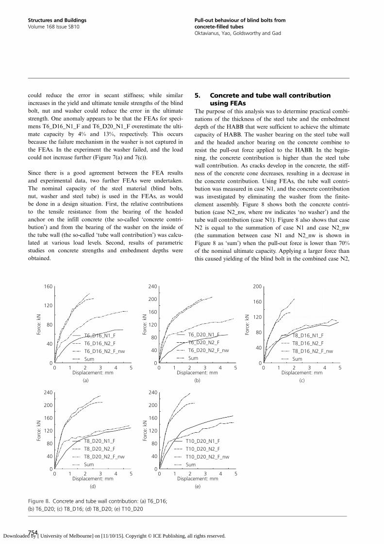
5. Concrete and tube wall contributionusing FEAs
The purpose of this analysis was to determine practical combi-nations of the thickness of the steel tube and the embedmentdepth of the HABB that were sufficient to achieve the ultimatecapacity of HABB. The washer bearing on the steel tube walland the headed anchor bearing on the concrete combine toresist the pull-out force applied to the HABB. In the begin-ning, the concrete contribution is higher than the steel tubewall contribution. As cracks develop in the concrete, the stiff-ness of the concrete cone decreases, resulting in a decrease inthe concrete contribution. Using FEAs, the tube wall contri-bution was measured in case N1, and the concrete contributionwas investigated by eliminating the washer from the finite-element assembly. Figure 8 shows both the concrete contri-bution (case N2_nw, where nw indicates ‘no washer’) and thetube wall contribution (case N1). Figure 8 also shows that caseN2 is equal to the summation of case N1 and case N2_nw(the summation between case N1 and N2_nw is shown inFigure 8 as ‘sum’) when the pull-out force is lower than 70%of the nominal ultimate capacity. Applying a larger force thanthis caused yielding of the blind bolt in the combined case N2,
0 1 2 3 4 5Displacement: mm
(b)
0 1 2 3 4 5Displacement: mm
(a)
0 1 2 3 4 5Displacement: mm
(c)
160
160
120
80
40
0
200
200
160
120
80
40
240
120
80
40
00
Forc
e: k
N
Forc
e: k
N
Forc
e: k
N
0 1 2 3 4 5Displacement: mm
(e)
160
200
240
120
80
40
0
Forc
e: k
N
0 1 2 3 4 5Displacement: mm
(d)
160
200
240
120
80
40
0
Forc
e: k
N
T8_D16_N1_F
T8_D16_N2_F
T8_D16_N2_F_nw
Sum
T6_D20_N1_F
T6_D20_N2_F
T6_D20_N2_F_nw
Sum
T6_D16_N1_F
T6_D16_N2_F
T6_D16_N2_F_nw
Sum
T8_D20_N1_F
T8_D20_N2_F
T8_D20_N2_F_nw
Sum
T10_D20_N1_F
T10_D20_N2_F
T10_D20_N2_F_nw
Sum
Figure 8. Concrete and tube wall contribution: (a) T6_D16;(b) T6_D20; (c) T8_D16; (d) T8_D20; (e) T10_D20
754
Structures and BuildingsVolume 168 Issue SB10
Pull-out behaviour of blind bolts fromconcrete-filled tubesOktavianus, Yao, Goldsworthy and Gad
Downloaded by [ University of Melbourne] on [11/10/15]. Copyright © ICE Publishing, all rights reserved.
whereas the blind bolt in the individual case N1 and caseN2_nw would still be in the elastic state, and hence inaccuracywould occur if direct summation of case N1 and case N2_nwwere to be performed for loads exceeding 70% of the nominalultimate capacity.
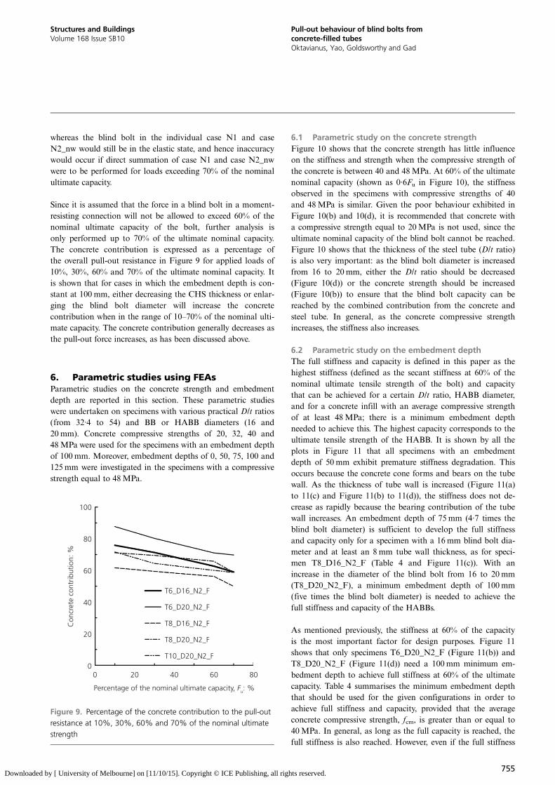
Since it is assumed that the force in a blind bolt in a moment-resisting connection will not be allowed to exceed 60% of thenominal ultimate capacity of the bolt, further analysis isonly performed up to 70% of the ultimate nominal capacity.The concrete contribution is expressed as a percentage ofthe overall pull-out resistance in Figure 9 for applied loads of10%, 30%, 60% and 70% of the ultimate nominal capacity. Itis shown that for cases in which the embedment depth is con-stant at 100 mm, either decreasing the CHS thickness or enlar-ging the blind bolt diameter will increase the concretecontribution when in the range of 10–70% of the nominal ulti-mate capacity. The concrete contribution generally decreases asthe pull-out force increases, as has been discussed above.
6. Parametric studies using FEAsParametric studies on the concrete strength and embedmentdepth are reported in this section. These parametric studieswere undertaken on specimens with various practical D/t ratios(from 32·4 to 54) and BB or HABB diameters (16 and20mm). Concrete compressive strengths of 20, 32, 40 and48MPa were used for the specimens with an embedment depthof 100mm. Moreover, embedment depths of 0, 50, 75, 100 and125mm were investigated in the specimens with a compressivestrength equal to 48MPa.
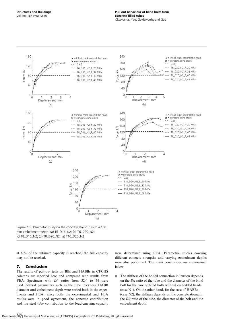
6.1 Parametric study on the concrete strengthFigure 10 shows that the concrete strength has little influenceon the stiffness and strength when the compressive strength ofthe concrete is between 40 and 48MPa. At 60% of the ultimatenominal capacity (shown as 0·6Fu in Figure 10), the stiffnessobserved in the specimens with compressive strengths of 40and 48MPa is similar. Given the poor behaviour exhibited inFigure 10(b) and 10(d), it is recommended that concrete witha compressive strength equal to 20MPa is not used, since theultimate nominal capacity of the blind bolt cannot be reached.Figure 10 shows that the thickness of the steel tube (D/t ratio)is also very important: as the blind bolt diameter is increasedfrom 16 to 20mm, either the D/t ratio should be decreased(Figure 10(d)) or the concrete strength should be increased(Figure 10(b)) to ensure that the blind bolt capacity can bereached by the combined contribution from the concrete andsteel tube. In general, as the concrete compressive strengthincreases, the stiffness also increases.
6.2 Parametric study on the embedment depthThe full stiffness and capacity is defined in this paper as thehighest stiffness (defined as the secant stiffness at 60% of thenominal ultimate tensile strength of the bolt) and capacitythat can be achieved for a certain D/t ratio, HABB diameter,and for a concrete infill with an average compressive strengthof at least 48MPa; there is a minimum embedment depthneeded to achieve this. The highest capacity corresponds to theultimate tensile strength of the HABB. It is shown by all theplots in Figure 11 that all specimens with an embedmentdepth of 50 mm exhibit premature stiffness degradation. Thisoccurs because the concrete cone forms and bears on the tubewall. As the thickness of tube wall is increased (Figure 11(a)to 11(c) and Figure 11(b) to 11(d)), the stiffness does not de-crease as rapidly because the bearing contribution of the tubewall increases. An embedment depth of 75 mm (4·7 times theblind bolt diameter) is sufficient to develop the full stiffnessand capacity only for a specimen with a 16mm blind bolt dia-meter and at least an 8 mm tube wall thickness, as for speci-men T8_D16_N2_F (Table 4 and Figure 11(c)). With anincrease in the diameter of the blind bolt from 16 to 20mm(T8_D20_N2_F), a minimum embedment depth of 100mm(five times the blind bolt diameter) is needed to achieve thefull stiffness and capacity of the HABBs.
As mentioned previously, the stiffness at 60% of the capacityis the most important factor for design purposes. Figure 11shows that only specimens T6_D20_N2_F (Figure 11(b)) andT8_D20_N2_F (Figure 11(d)) need a 100mm minimum em-bedment depth to achieve full stiffness at 60% of the ultimatecapacity. Table 4 summarises the minimum embedment depththat should be used for the given configurations in order toachieve full stiffness and capacity, provided that the averageconcrete compressive strength, fcm, is greater than or equal to40MPa. In general, as long as the full capacity is reached, thefull stiffness is also reached. However, even if the full stiffness
100
80
60
40
20
Percentage of the nominal ultimate capacity, Fu: %
0
T6_D16_N2_F
T6_D20_N2_F
T8_D16_N2_F
T8_D20_N2_F
T10_D20_N2_F
0 20 40 60 80
Con
cret
e co
ntrib
utio
n: %
Figure 9. Percentage of the concrete contribution to the pull-outresistance at 10%, 30%, 60% and 70% of the nominal ultimatestrength
755
Structures and BuildingsVolume 168 Issue SB10
Pull-out behaviour of blind bolts fromconcrete-filled tubesOktavianus, Yao, Goldsworthy and Gad
Downloaded by [ University of Melbourne] on [11/10/15]. Copyright © ICE Publishing, all rights reserved.
at 60% of the ultimate capacity is reached, the full capacitymay not be reached.
7. ConclusionThe results of pull-out tests on BBs and HABBs in CFCHScolumns are reported here and compared with results fromFEA. Specimens with D/t ratios from 32·4 to 54 wereused. Several parameters such as the tube thickness, HABBdiameter and embedment depth were varied both in the exper-iments and FEA. Since both the experimental and FEAresults were in good agreement, the concrete contributionand the steel tube contribution to the load-carrying capacity
were determined using FEA. Parametric studies coveringdifferent concrete strengths and varying embedment depthswere also performed. The main conclusions are summarisedbelow.
& The stiffness of the bolted connection in tension dependson the D/t ratio of the tube and the diameter of the blindbolt for the case of blind bolts without embedded heads(case N1). On the other hand, for the case of HABBs(case N2), the stiffness depends on the concrete strength,the D/t ratio of the tube, the diameter of the bolt and theembedment depth.
160
120
80
40
00 1 2 3 4
Displacement: mm
(a)
0 1 2 3 4Displacement: mm
(d)
0 1 2 3 4Displacement: mm
(e)
0 1 2 3 4 5Displacement: mm
(b)
Forc
e: k
N 160
200
240
120
80
40
0
Forc
e: k
N
160
200
240
120
80
40
0
Forc
e: k
N
160
200
240
120
80
40
0
Forc
e: k
N
160
120
80
40
00 1 2 3
Displacement: mm
(c)
Forc
e: k
N
initial crack around the headconcrete cone crack
T6_D16_N2_F_20 MPa
T6_D16_N2_F_32 MPa
T6_D16_N2_F_40 MPa
T6_D16_N2_F_48 MPa
0.6Fu
initial crack around the headconcrete cone crack
T8_D16_N2_F_20 MPa
T8_D16_N2_F_32 MPa
T8_D16_N2_F_40 MPa
T8_D16_N2_F_48 MPa
0.6Fu
initial crack around the headconcrete cone crack
T8_D20_N2_F_20 MPa
T8_D20_N2_F_32 MPa
T8_D20_N2_F_40 MPa
T8_D20_N2_F_48 MPa
0.6Fu
initial crack around the headconcrete cone crack
T6_D20_N2_F_20 MPa
T6_D20_N2_F_32 MPa
T6_D20_N2_F_40 MPa
T6_D20_N2_F_48 MPa
0.6Fu
initial crack around the headconcrete cone crack
T10_D20_N2_F_20 MPa
T10_D20_N2_F_32 MPa
T10_D20_N2_F_40 MPa
T10_D20_N2_F_48 MPa
0.6Fu
Figure 10. Parametric study on the concrete strength with a 100mm embedment depth: (a) T6_D16_N2; (b) T6_D20_N2;(c) T8_D16_N2; (d) T8_D20_N2; (e) T10_D20_N2
756
Structures and BuildingsVolume 168 Issue SB10
Pull-out behaviour of blind bolts fromconcrete-filled tubesOktavianus, Yao, Goldsworthy and Gad
Downloaded by [ University of Melbourne] on [11/10/15]. Copyright © ICE Publishing, all rights reserved.
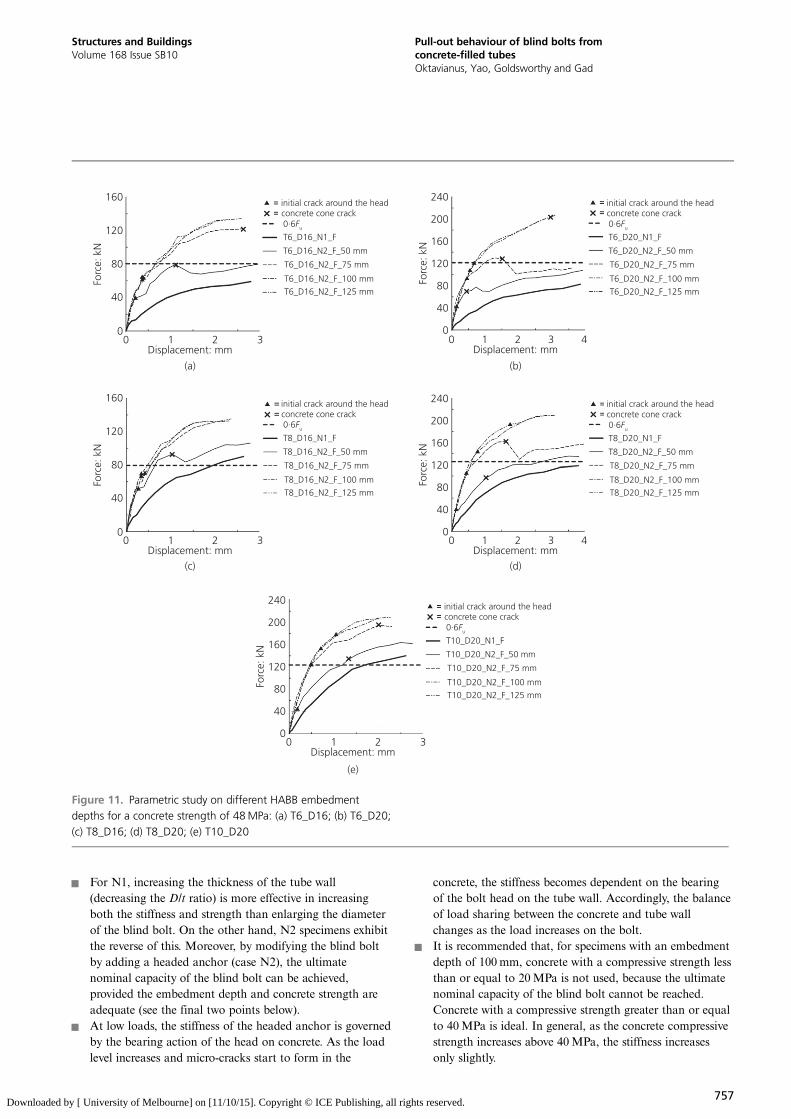
& For N1, increasing the thickness of the tube wall(decreasing the D/t ratio) is more effective in increasingboth the stiffness and strength than enlarging the diameterof the blind bolt. On the other hand, N2 specimens exhibitthe reverse of this. Moreover, by modifying the blind boltby adding a headed anchor (case N2), the ultimatenominal capacity of the blind bolt can be achieved,provided the embedment depth and concrete strength areadequate (see the final two points below).
& At low loads, the stiffness of the headed anchor is governedby the bearing action of the head on concrete. As the loadlevel increases and micro-cracks start to form in the
concrete, the stiffness becomes dependent on the bearingof the bolt head on the tube wall. Accordingly, the balanceof load sharing between the concrete and tube wallchanges as the load increases on the bolt.
& It is recommended that, for specimens with an embedmentdepth of 100mm, concrete with a compressive strength lessthan or equal to 20MPa is not used, because the ultimatenominal capacity of the blind bolt cannot be reached.Concrete with a compressive strength greater than or equalto 40MPa is ideal. In general, as the concrete compressivestrength increases above 40MPa, the stiffness increasesonly slightly.
160
120
80
40
initial crack around the headconcrete cone crack
T6_D16_N1_F
T6_D16_N2_F_50 mm
T6_D16_N2_F_75 mm
T6_D16_N2_F_100 mm
T6_D16_N2_F_125 mm
initial crack around the headconcrete cone crack
T8_D16_N1_F
T8_D16_N2_F_50 mm
T8_D16_N2_F_75 mm
T8_D16_N2_F_100 mm
T8_D16_N2_F_125 mm
0·6Fu
0·6Fu
initial crack around the headconcrete cone crack
T6_D20_N1_F
T6_D20_N2_F_50 mm
T6_D20_N2_F_75 mm
T6_D20_N2_F_100 mm
T6_D20_N2_F_125 mm
0·6Fu
initial crack around the headconcrete cone crack
T8_D20_N1_F
T8_D20_N2_F_50 mm
T8_D20_N2_F_75 mm
T8_D20_N2_F_100 mm
T8_D20_N2_F_125 mm
0·6Fu
initial crack around the headconcrete cone crack
T10_D20_N1_F
T10_D20_N2_F_50 mm
T10_D20_N2_F_75 mm
T10_D20_N2_F_100 mm
T10_D20_N2_F_125 mm
0·6Fu
00 1 2 3
Displacement: mm
(a) (b)
(c) (d)
(e)
0 1 2 3Displacement: mm
0 1 2 3Displacement: mm
0 1 2 3 4Displacement: mm
0 1 2 3 4Displacement: mm
Forc
e: k
N 160
200
240
120
80
40
0
Forc
e: k
N
160
200
240
120
80
40
0
Forc
e: k
N
160
200
240
120
80
40
0
Forc
e: k
N
160
120
80
40
0
Forc
e: k
N
Figure 11. Parametric study on different HABB embedmentdepths for a concrete strength of 48MPa: (a) T6_D16; (b) T6_D20;(c) T8_D16; (d) T8_D20; (e) T10_D20
757
Structures and BuildingsVolume 168 Issue SB10
Pull-out behaviour of blind bolts fromconcrete-filled tubesOktavianus, Yao, Goldsworthy and Gad
Downloaded by [ University of Melbourne] on [11/10/15]. Copyright © ICE Publishing, all rights reserved.
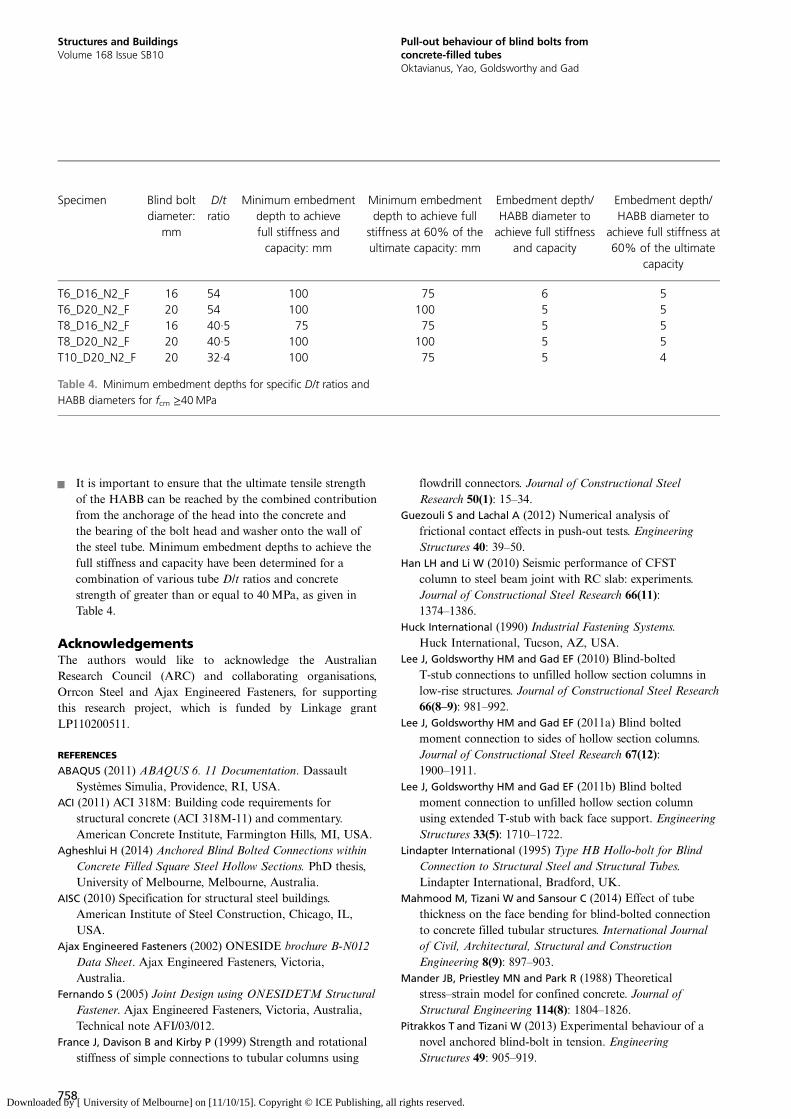
& It is important to ensure that the ultimate tensile strengthof the HABB can be reached by the combined contributionfrom the anchorage of the head into the concrete andthe bearing of the bolt head and washer onto the wall ofthe steel tube. Minimum embedment depths to achieve thefull stiffness and capacity have been determined for acombination of various tube D/t ratios and concretestrength of greater than or equal to 40MPa, as given inTable 4.
AcknowledgementsThe authors would like to acknowledge the AustralianResearch Council (ARC) and collaborating organisations,Orrcon Steel and Ajax Engineered Fasteners, for supportingthis research project, which is funded by Linkage grantLP110200511.
REFERENCES
ABAQUS (2011) ABAQUS 6. 11 Documentation. DassaultSystèmes Simulia, Providence, RI, USA.
ACI (2011) ACI 318M: Building code requirements forstructural concrete (ACI 318M-11) and commentary.American Concrete Institute, Farmington Hills, MI, USA.
Agheshlui H (2014) Anchored Blind Bolted Connections withinConcrete Filled Square Steel Hollow Sections. PhD thesis,University of Melbourne, Melbourne, Australia.
AISC (2010) Specification for structural steel buildings.American Institute of Steel Construction, Chicago, IL,USA.
Ajax Engineered Fasteners (2002) ONESIDE brochure B-N012Data Sheet. Ajax Engineered Fasteners, Victoria,Australia.
Fernando S (2005) Joint Design using ONESIDETM StructuralFastener. Ajax Engineered Fasteners, Victoria, Australia,Technical note AFI/03/012.
France J, Davison B and Kirby P (1999) Strength and rotationalstiffness of simple connections to tubular columns using
flowdrill connectors. Journal of Constructional SteelResearch 50(1): 15–34.
Guezouli S and Lachal A (2012) Numerical analysis offrictional contact effects in push-out tests. EngineeringStructures 40: 39–50.
Han LH and Li W (2010) Seismic performance of CFSTcolumn to steel beam joint with RC slab: experiments.Journal of Constructional Steel Research 66(11):1374–1386.
Huck International (1990) Industrial Fastening Systems.Huck International, Tucson, AZ, USA.
Lee J, Goldsworthy HM and Gad EF (2010) Blind-boltedT-stub connections to unfilled hollow section columns inlow-rise structures. Journal of Constructional Steel Research66(8–9): 981–992.
Lee J, Goldsworthy HM and Gad EF (2011a) Blind boltedmoment connection to sides of hollow section columns.Journal of Constructional Steel Research 67(12):1900–1911.
Lee J, Goldsworthy HM and Gad EF (2011b) Blind boltedmoment connection to unfilled hollow section columnusing extended T-stub with back face support. EngineeringStructures 33(5): 1710–1722.
Lindapter International (1995) Type HB Hollo-bolt for BlindConnection to Structural Steel and Structural Tubes.Lindapter International, Bradford, UK.
Mahmood M, Tizani W and Sansour C (2014) Effect of tubethickness on the face bending for blind-bolted connectionto concrete filled tubular structures. International Journalof Civil, Architectural, Structural and ConstructionEngineering 8(9): 897–903.
Mander JB, Priestley MN and Park R (1988) Theoreticalstress–strain model for confined concrete. Journal ofStructural Engineering 114(8): 1804–1826.
Pitrakkos T and Tizani W (2013) Experimental behaviour of anovel anchored blind-bolt in tension. EngineeringStructures 49: 905–919.
Specimen Blind boltdiameter:
mm
D/tratio
Minimum embedmentdepth to achievefull stiffness andcapacity: mm
Minimum embedmentdepth to achieve full
stiffness at 60% of theultimate capacity: mm
Embedment depth/HABB diameter toachieve full stiffness
and capacity
Embedment depth/HABB diameter to
achieve full stiffness at60% of the ultimate
capacity
T6_D16_N2_F 16 54 100 75 6 5T6_D20_N2_F 20 54 100 100 5 5T8_D16_N2_F 16 40·5 75 75 5 5T8_D20_N2_F 20 40·5 100 100 5 5T10_D20_N2_F 20 32·4 100 75 5 4
Table 4. Minimum embedment depths for specific D/t ratios andHABB diameters for fcm ≥40MPa
758
Structures and BuildingsVolume 168 Issue SB10
Pull-out behaviour of blind bolts fromconcrete-filled tubesOktavianus, Yao, Goldsworthy and Gad
Downloaded by [ University of Melbourne] on [11/10/15]. Copyright © ICE Publishing, all rights reserved.
Standards Association of Australia (1991) AS1163: Structuralsteel hollow sections. Standards Australia, Homebush,Australia.
Standards Australia (1998) AS 4100: Steel structures. StandardsAustralia, Sydney, Australia.
Standards Australia (2000) AS 4291: Mechanical properties offasteners made of carbon steel and alloy steel. StandardsAustralia, Strathfield, Australia.
Standards Australia (2009) AS 3600: Concrete structures.Standards Australia, Sydney, Australia.
Standards Australia (2010) AS 3972: General purpose andblended cements. Standards Australia, Sydney, Australia.
Yao H, Goldsworthy HM and Gad EF (2008) Experimental andnumerical investigation of the tensile behaviour ofblind-bolted T-stub connections to concrete-filled circularcolumn. Journal of Structural Engineering 134(2): 198–208.
Yao H, Goldsworthy HM, Gad EF et al. (2011) Experimentalstudy on modified blind bolts anchored in concrete-filledsteel tubular columns. Australian Earthquake EngineeringSociety Conference, Barossa Valley, Australia.
WHAT DO YOU THINK?
To discuss this paper, please email up to 500 words to theeditor at [email protected]. Your contribution will beforwarded to the author(s) for a reply and, if consideredappropriate by the editorial panel, will be published asdiscussion in a future issue of the journal.
Proceedings journals rely entirely on contributions sent inby civil engineering professionals, academics and stu-dents. Papers should be 2000–5000 words long (briefingpapers should be 1000–2000 words long), with adequateillustrations and references. You can submit your paperonline via www.icevirtuallibrary.com/content/journals,where you will also find detailed author guidelines.
759
Structures and BuildingsVolume 168 Issue SB10
Pull-out behaviour of blind bolts fromconcrete-filled tubesOktavianus, Yao, Goldsworthy and Gad
Downloaded by [ University of Melbourne] on [11/10/15]. Copyright © ICE Publishing, all rights reserved.