Embed Size (px)
Citation preview

UF20.481 – U-Series 48V, 20A, 100ms
Nov 2005 / Rev. 1.1 / DS-UF20.481-EN / All parameters are specified at 48V, 10A and 25°C ambient unless otherwise noted.
www.pulspower.com Phone +49 89 9278 0 Germany 1/11
BUFFER UNIT ■ Buffering with electrolytic capacitors instead
of lead batteries ■ Buffering of 48V loads ■ Minimum hold-up time 0.1s at 20A and 0.2s at 10A ■ Longer hold-up time at lower loads ■ Clear status indication by status LED and signaling
terminals ■ Quick-connect spring-clamp terminals ■ 3 Year warranty
1. GENERAL DESCRIPTION 2. SHORT-FORM DATA Rated voltage DC 48V Voltage range 48-56V Output voltage 45V or
VIN –2V Buffer mode select with jumper
Output current 0 to 20A Hold-up time min 0.1s 45V, 20A
typ 0.15s 45V, 20A
min 13.4s 45V, 0.1A typ 21s 45V, 0.1A Charging current max 500mA Charging time typ. 21s Input current typ 40mA standby mode Power dissipation typ 1.9W standby mode Temperature range -25°C to +70°C operational Dimensions 64x124x102mm WxHxD
The buffer unit is a supplementarry device for regulated DC48V power supplies. It buffers load currents during typical mains faults and load peaks.
Working principle
In times when the power supply provides sufficient voltages, the buffer unit stores energy in integrated electrolytic capacitors. In case of mains voltage fault, this energy is released again in a regulated process.
Bridges mains faults without interruption
Statistic show that 80% of all mains fault lasts less than 0.2s. These mains faults are completely bridged by the buffer unit. This increases the reliability of the system as a whole.
Extended hold-up time
Once mains power fails or is switched off, the buffer unit will continue to provide the load current for a defined period of time. Process data can be saved and processes can be terminated before the DC power switches off. Controlled restarts are subsequently possible.
Easy to handle, expandable and maintanance-free
The buffer unit does not require any control wiring. It can be added parallel to the load circuit at any given point. Buffer units can be switched in parallel to increase the output ampacity or the hold-up time.
3. ORDER NUMBERS 4. MARKINGS Buffer Unit UF20.481 48V, 20A, 100ms
Accessory ZM1.WALL Wall mounting
bracket
ZM14.SIDE Side mounting
bracket
XF-1x4s/270-60 Mating connector, Part of derlivery
UL 508
UL 60950-1
EMC, LVD
DCCharge
Discharge
Buffer
DC
BufferUnit(s)
PowerSupply LoadAC
+-
AC
DCBuffer Unit
AC
DCBuffer Unit
2 rue René Laennec 51500 Taissy France Fax: 03 26 85 19 08, Tel : 03 26 82 49 29
E-mail:[email protected] web : www.hvssystem.com

UF20.481 – U-Series 48V, 20A, 100ms
Nov 2005 / Rev. 1.1 / DS-UF20.481-EN / All parameters are specified at 48V, 10A and 25°C ambient unless otherwise noted.
www.pulspower.com Phone +49 89 9278 0 Germany 2/11
INDEX PAGE INDEX PAGE
1. General Description .................................... 1 2. Short-form Data .......................................... 1 3. Order Numbers............................................ 1 4. Markings ...................................................... 1 5. Standby Mode ............................................. 3 6. Charging Mode ........................................... 3 7. Buffer Mode ................................................ 4 8. Functional Diagram..................................... 5 9. Front Side and User Elements..................... 5 10. Operating Diagram..................................... 6 11. Active and Ready Signal, Inhibit Input ...... 6
12. Terminals and Wiring ................................. 7 13. Reliability..................................................... 7 14. EMC.............................................................. 8 15. Environment................................................ 8 16. Protection Features..................................... 9 17. Safety ........................................................... 9 18. Approvals..................................................... 9 19. Fulfilled Standards ...................................... 9 20. Physical Dimensions and Weight ............. 10 21. Wiring Diagrams ....................................... 11
INSTALLATION NOTES Mounting Orientation: The power terminal shall be located on top of the unit.
Cooling Convection cooled, no forced air cooling required. Do not obstruct air flow!
Installation clearances: No special clearances necessary
Intended use This buffer unit has been designed for use in panel board installations or other building-in applications where a suitable mechanical enclosure shall be provided to fulfil local requirements.
Service parts: The unit does not contain any service parts. If damage or malfunctioning should occur during operation, immediately turn power off and send unit for inspection to factory!
DISCLAIMER The information presented in this document is believed to be accurate and reliable and may change without notice.
2 rue René Laennec 51500 Taissy France Fax: 03 26 85 19 08, Tel : 03 26 82 49 29
E-mail:[email protected] web : www.hvssystem.com

UF20.481 – U-Series 48V, 20A, 100ms
Nov 2005 / Rev. 1.1 / DS-UF20.481-EN / All parameters are specified at 48V, 10A and 25°C ambient unless otherwise noted.
www.pulspower.com Phone +49 89 9278 0 Germany 3/11
5. STANDBY MODE
Input voltage nom. DC 48V Voltage range nom. 48-56Vdc Input current typ. 40mA Power dissipation typ. 1.9W Status lamp permanent on Active signal high ohmic Ready signal low ohmic
6. CHARGING MODE
Input current min. 0.3A Charging mode max. 0.5A Charging mode
Charging time min. 22s / 17s Initial charge1) / Re-charging2) max. 32s / 25s Initial charge1) / Re-charging2) Status lamp flashes 1.25Hz Active signal high ohmic Ready signal high ohmic
1) Initial charging is the first charge after voltage is applied to the buffer unit.
2) Re-charging is the charging of the internal capacitors after voltage interruptions shorter than 2minutes.
Fig. 6-1 Buffer charging time, 48V
Charge
200 5 10 30s
Charging Time
40
80
60
100%
15 20 25
maxmin
2 rue René Laennec 51500 Taissy France Fax: 03 26 85 19 08, Tel : 03 26 82 49 29
E-mail:[email protected] web : www.hvssystem.com

UF20.481 – U-Series 48V, 20A, 100ms
Nov 2005 / Rev. 1.1 / DS-UF20.481-EN / All parameters are specified at 48V, 10A and 25°C ambient unless otherwise noted.
www.pulspower.com Phone +49 89 9278 0 Germany 4/11
7. BUFFER MODE
Rated output current nom. 20A Current limitation min. 20A Electronically limited Output voltage typ. 45V Jumper in position “45V fixed”
typ. 2V below the input voltage
Jumper in position “Vin –2V”
Ripple and noise voltage max. 250mVpp 5A, 20Hz to 20MHz, 50Ohm max. 400mVpp 10A, 20Hz to 20MHz, 50Ohm max. 600mVpp 20A, 20Hz to 20MHz, 50Ohm may increase below –10°C Hold-up time min. 0.1s 45V, 20A typ. 0.15s 45V, 20A min. 13.4s 45V, 0.1A typ. 21s 45V, 0.1A
To increase buffer current or extend hold-up time any given number of buffer units can be put in parallel
Activation threshold typ. 45V Jumper in position “45V fixed”
Buffering starts if terminal voltage falls below 45V
typ. Vin –2V Jumper in position “Vin –2V” Buffering starts if the terminal voltage decreases by more than 2V. Buffering ends when terminal voltage increases by more than 2V Voltage changes slower than 1.1V/s will be ignored unless the voltage is above 45V. Below 45V buffering starts immediately.
Status lamp flashes 10Hz Active signal low ohmic Ready signal high ohmic
Fig. 7-1 Hold-up time
0,01 A
0,10 A
1,00 A
10,00 A
100,00 A
0,1 s 1,0 s 10,0 s 100,0 s
Buffer Current
typ. ( 45,0 V )typ. ( 56,0 V )min. ( 45 V )
2 rue René Laennec 51500 Taissy France Fax: 03 26 85 19 08, Tel : 03 26 82 49 29
E-mail:[email protected] web : www.hvssystem.com

UF20.481 – U-Series 48V, 20A, 100ms
Nov 2005 / Rev. 1.1 / DS-UF20.481-EN / All parameters are specified at 48V, 10A and 25°C ambient unless otherwise noted.
www.pulspower.com Phone +49 89 9278 0 Germany 5/11
8. FUNCTIONAL DIAGRAM
Fig. 8-1 Functional diagram
Buffer CapacitorCharger &
Inrush Limiter
BufferCapacitor
Buffer CapacitorDischarger
Statuslamp
7 Active
6 +
Ready Monitor
+-
Active Monitor
+-
Optokoppler
Optokoppler
8 Ready
9 Inhibit
Optokoppler
BufferCapacitor
Shut-Down
Input / OutputVoltage Monitor
Back-upLevel
Selector
Reverse-Polarity
Protection
--++
Safety andOver-
VoltageProtection
ChassisGround
9. FRONT SIDE AND USER ELEMENTS
Fig. 9-1 Front side
I/O Power Port Quick-connect spring-clamp terminals, + Positive terminal - Negative terminal Chassis Ground to bond the housing
Status lamp
OFF: Buffer is discharged, or terminal voltage is below 44V ON: Unit is fully charged Flashes 1,25Hz: Unit is in charging mode Flashes 10Hz: Unit is in discharging mode
Signal Port Plug Connector 6 common + pole 7 Active: unit is buffering 8 Ready: unit is on stand-by 9 Inhibit: initiates buffer discharging and inhibits recharging of capacitors
Back-up threshold jumper
1-2: Fixed mode, (factory setting) Unit switches to buffer mode as soon as the voltage falls below 45V
2-3: Variable mode
Unit switches to buffer mode when terminal voltage decreases by 2V within 1.1V/s or the input voltage falls below 45V.
Missing jumper = 45V fixed
Set the unit to fixed mode:
- when power supplies other than the Dimension Q-Series are used
- with back-feeding loads
- when the buffer unit is placed close to the load
- whenever in doubt
Set the unit to variable mode:
- for 48V applications
- when the buffer unit is placed close to the power supply
2 rue René Laennec 51500 Taissy France Fax: 03 26 85 19 08, Tel : 03 26 82 49 29
E-mail:[email protected] web : www.hvssystem.com

UF20.481 – U-Series 48V, 20A, 100ms
Nov 2005 / Rev. 1.1 / DS-UF20.481-EN / All parameters are specified at 48V, 10A and 25°C ambient unless otherwise noted.
www.pulspower.com Phone +49 89 9278 0 Germany 6/11
10. OPERATING DIAGRAM
Fig. 10-1 Operating diagram Fig. 10-2 Signals schematic
Ready
tActive
t
Optocoupler high ohmic
Optocoupler high ohmic
Optocoupler low ohmic
Optocouplerlow ohmic
V Mains
tV Buffer Capacitor
tVout
t
Charging Mode
LED
t
Buffer Mode
Hold-up Time Power Supply
StandbyMode
10Hz1.25Hz
8 Ready
7 Active
6 +
5,1V
3mA9 InhibitUF20
11. ACTIVE AND READY SIGNAL, INHIBIT INPUT
Active signal (Pin 7) low ohmic while buffer capacitors are discharging Signal voltage max. 60Vdc Signal current max. 6mA Voltage drop across opto-coupler typ 1.2V / 3.3V at 1mA / 5mA, while opto-coupler is low ohmic Leakage current max. 50µA while opto-coupler is high ohmic Isolation nom. 500Vac signal port to power port Ready signal (Pin 8) low ohmic when buffer is fully charged Signal voltage max. 60Vdc Signal current max. 6mA Voltage drop across opto-coupler typ 1.2V / 3.3V at 1mA / 5mA, while opto-coupler is low ohmic Leakage current max. 50µA while opto-coupler is high ohmic Isolation nom. 500Vac signal port to power port Inhibit input (Pin 9) “High” input signal initiates unit shutdown and buffer discharge Signal voltage max. 60Vdc Signal current max. 4mA current limited Shut-down threshold min. 6Vdc unit is in shut-down mode above this threshold level max. 10Vdc Isolation nom. 500Vac signal port to power port
Wiring diagrams can be found in section 21.
2 rue René Laennec 51500 Taissy France Fax: 03 26 85 19 08, Tel : 03 26 82 49 29
E-mail:[email protected] web : www.hvssystem.com

UF20.481 – U-Series 48V, 20A, 100ms
Nov 2005 / Rev. 1.1 / DS-UF20.481-EN / All parameters are specified at 48V, 10A and 25°C ambient unless otherwise noted.
www.pulspower.com Phone +49 89 9278 0 Germany 7/11
12. TERMINALS AND WIRING
Power terminal
Type Bi-stable, quick-connect spring clamp terminals. IP20 Finger-safe construction. Suitable for field- and factory installation. Shipped in open position.
Solid wire 0.5-6mm2 Stranded wire 0.5-4mm2 AWG 20-10AWG Ferrules Allowed, but not required Pull-out force 10AWG:80N, 12AWG:60N, 14AWG:50N, 16AWG:40N (according to UL486E) Wire stripping length 10mm / 0.4inch
Fig. 12-1 Connecting a wire
Instructions:
a) Use appropriate copper cables, that are designed for an operating temperature of 60°C
b) Follow national installation codes and regulations!
c) Ensure that all strands of a stranded wire enter the terminal connection!
d) Up to two stranded wires with the same cross section are permitted in one connection point
1. Insert the wire 2. Snap the lever
To disconnect wire: same procedure vice versa
Signal terminal
Type Plug connector with screw terminal mechanism. Finger-touch-proof terminal with captive screws for 3.5mm slotted screwdriver.
Solid / stranded wire 0.2-2.5mm2 AWG 22-14AWG
Ferrules up to 1.5 mm2 wire gauge Wire stripping length 6mm / 0.24inch Tightening torque 0.4Nm, 3.5lb.in
13. RELIABILITY
Lifetime expectancy min. 41 000h 40°C, stand-by mode min. 116 000h 25°C, stand-by mode MTBF SN 29500, IEC 61709 2 348 000h 40°C, stand-by mode 4 062 000h 25°C, stand-by mode MTBF MIL HDBK 217F 405 000h 40°C, stand-by mode, ground benign GB40 555 000h 25°C, stand-by mode, ground benign GB25
The Lifetime expectancy shown in the table indicates the operating hours (service life) and is determined by the lifetime expectancy of the built-in electrolytic capacitors. Lifetime expectancy is specified in operational hours. Lifetime expectancy is calculated according to the capacitor’s manufacturer specification.
MTBF stands for Mean Time Between Failure, which is calculated according to the statistically device failures, and indicates reliability of a device. It is the statistical representation of the likelihood of a unit to fail and does not necessarily represent a life of a product.
2 rue René Laennec 51500 Taissy France Fax: 03 26 85 19 08, Tel : 03 26 82 49 29
E-mail:[email protected] web : www.hvssystem.com

UF20.481 – U-Series 48V, 20A, 100ms
Nov 2005 / Rev. 1.1 / DS-UF20.481-EN / All parameters are specified at 48V, 10A and 25°C ambient unless otherwise noted.
www.pulspower.com Phone +49 89 9278 0 Germany 8/11
14. EMC
The unit is suitable for applications in industrial environment as well as in residential, commercial and light industry environment without any restrictions. CE mark is in conformance with EMC guideline 89/336/EEC and 93/68/EEC and the low-voltage directive (LVD) 73/23/EWG.
A detailed EMC Report is available on request
EMC Immunity EN 61000-6-1 EN 61000-6-2 Generic standards
Electrostatic discharge 1) EN 61000-4-2 Contact discharge
Air discharge 8kV 15kV
Criterion A Criterion A
Electromagnetic RF field EN 61000-4-3 80MHz-1GHz 10V/m Criterion A Fast transients (Burst) EN 61000-4-4 2kV Criterion A
Surge voltage EN 61000-4-5 + -
+ / - housing 500V 500V
Criterion A Criterion A
Conducted disturbance EN 61000-4-6 0,15-80MHz 10V Criterion A
1) Din-Rail earthed
EMC Emission EN 61000-6-3 and EN 61000-6-4 Generic standards Conducted emission EN 55022 Class B Radiated emission EN 55011, EN 55022 Class B
This device complies with FCC Part 15 rules. Operation is subjected to following two conditions: (1) this device may not cause harmful interference, and (2) this device must accept any interference received, including interference that may cause undesired operation.
15. ENVIRONMENT
Operational temperature -25°C to +70°C full power Storage temperature -40 to +85°C storage and transportation Humidity 5 to 95% r.H. no condensation allowed Vibration sinusoidal 2-17.8Hz: ±1.6mm; 17.8-500Hz: 2g IEC 60068-2-6 Vibration random 0.5m2(s3) IEC 60068-2-64 Shock 30g 6ms, 20g 11ms IEC 60068-2-27 Altitude 0 to 6000m All approvals apply only up to 2000m Over-voltage category III EN 50178 II EN 50178 above 2000m altitude Degree of pollution 2 EN 50178, not conductive
The ambient temperature is defined 2cm below the unit.
2 rue René Laennec 51500 Taissy France Fax: 03 26 85 19 08, Tel : 03 26 82 49 29
E-mail:[email protected] web : www.hvssystem.com

UF20.481 – U-Series 48V, 20A, 100ms
Nov 2005 / Rev. 1.1 / DS-UF20.481-EN / All parameters are specified at 48V, 10A and 25°C ambient unless otherwise noted.
www.pulspower.com Phone +49 89 9278 0 Germany 9/11
16. PROTECTION FEATURES
Buffer protection Electronically protected against overload, no-load and short-circuits Output over-voltage protection
in buffer mode typ. 58Vdc max. 60Vdc
In case of an internal defect, a redundant circuitry limits the maximum output voltage. The output shuts-down and makes restart attempts automatically.
Degree of protection IP 20 EN/IEC 60529 Penetration protection > 3.5mm e.g. screws, small parts Reverse polarity protection yes max. –60Vdc Input over-voltages protection yes max. 60Vdc, no harm or defect of the unit Internal fuse not included
17. SAFETY
Output voltage SELV IEC/EN 60950-1 PELV EN 60204-1, EN 50178, IEC 60364-4-41 Class of protection II Isolation resistance > 5MOhm Power-port to housing, 500Vdc PE resistance < 0.1Ohm between housing and chassis ground terminal Dielectric strength 500Vac Power-port to signal-port 500Vac Power-port / signal-port to housing
18. APPROVALS
UL 508
IND. CONT. EQ.
18WM
LISTED E198865 listed for use in U.S.A. (UL 508) and Canada (C22.2 No. 14-95) Industrial Control Equipment
UL 60950-1
RECOGNIZED E137006 recognized for the use in U.S.A. (UL 60950-1) and Canada (C22.2 No. 60950) Information Technology Equipment, Level 5
IEC 60950-1 IECEE
CB SCHEME
CB Scheme, Information Technology Equipment
19. FULFILLED STANDARDS
EN/IEC 60204-1 Safety of Electrical Equipment of Machines
EN/IEC 61131 Programmable Controllers
EN 50178 Electronic Equipment in Power Installations
2 rue René Laennec 51500 Taissy France Fax: 03 26 85 19 08, Tel : 03 26 82 49 29
E-mail:[email protected] web : www.hvssystem.com
UF20.481 – U-Series 48V, 20A, 100ms
Nov 2005 / Rev. 1.1 / DS-UF20.481-EN / All parameters are specified at 48V, 10A and 25°C ambient unless otherwise noted.
www.pulspower.com Phone +49 89 9278 0 Germany 10/11
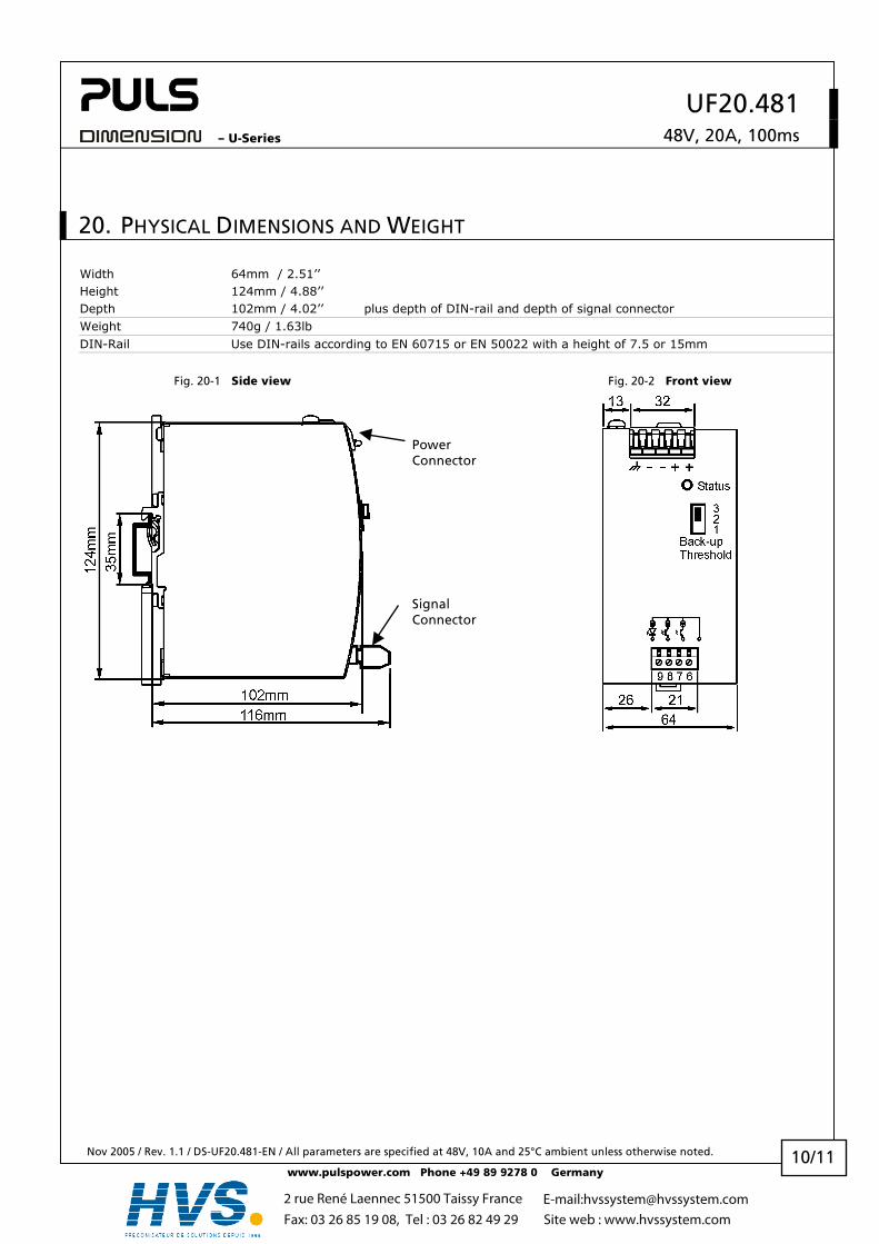
20. PHYSICAL DIMENSIONS AND WEIGHT
Width 64mm / 2.51’’ Height 124mm / 4.88’’ Depth 102mm / 4.02’’ plus depth of DIN-rail and depth of signal connector Weight 740g / 1.63lb DIN-Rail Use DIN-rails according to EN 60715 or EN 50022 with a height of 7.5 or 15mm
Fig. 20-1 Side view Fig. 20-2 Front view
Signal Connector
Power Connector
2 rue René Laennec 51500 Taissy France Fax: 03 26 85 19 08, Tel : 03 26 82 49 29
E-mail:[email protected] web : www.hvssystem.com

UF20.481 – U-Series 48V, 20A, 100ms
Nov 2005 / Rev. 1.1 / DS-UF20.481-EN / All parameters are specified at 48V, 10A and 25°C ambient unless otherwise noted.
www.pulspower.com Phone +49 89 9278 0 Germany 11/11
21. WIRING DIAGRAMS
Fig. 21-1 General wiring diagram Fig. 21-2 Signals supplied from an external voltage
L N PE
+ + - -
PowerSupply
Adj
OverloadDCok
optional
LN
PE
+ +- -
UF20Buffer Unit
Back-upThreshold
Status
6 +
7 Ac
tive
8 Re
ady
9 Inh
ibit
Load
+ -
Inhi
bit
Act
ive
Rel
ay, l
amp
or s
igna
l
Rea
dyR
elay
, lam
p or
sig
nal
+
+ +- -
UF20Buffer Unit
Back-upThreshold
Status
6 +
7 Ac
tive
8 Re
ady
9 Inh
ibit In
hibi
t
Act
ive
Rel
ay, l
amp
or s
igna
l
Rea
dyR
elay
, lam
p or
sig
nal
Fig. 21-3 Paralleling of buffer units Fig. 21-4 Decoupling of buffered branches
L N PE
+ + - -
PowerSupply
Adj
OverloadDCok
optional
LN
PE
+ +- -
UF20Buffer Unit
Back-upThreshold
Status
6 +
7 Ac
tive
8 Re
ady
9 Inh
ibit
Load
+ -+ +- -
UF20Buffer Unit
Back-upThreshold
Status
6 +
7 Ac
tive
8 Re
ady
9 Inh
ibit
L N PE
+ + - -
PowerSupply
Adj
OverloadDCok
optional
LN
PE
+ +- -
UF20Buffer Unit
Back-upThreshold
Status
6 +
7 Ac
tive
8 Re
ady
9 Inh
ibit
Un-buffered
Load
+ -
YR2.DiodeDecouplingModule
+ -OUT
+ -IN 1
+ -IN 2
BufferedLoad
+ -
2 rue René Laennec 51500 Taissy France Fax: 03 26 85 19 08, Tel : 03 26 82 49 29
E-mail:[email protected] web : www.hvssystem.com