Embed Size (px)
Citation preview
Pulsed Power Physics Branch, Plasma Physics Division D. Mosher 1PFRP MHD
NRLNRL
Symposium on Recent Advances in Plasma Physics June 10-12, 2007
The Plasma-Filled Rod Pinch:a Pulsed-Power HED Plasma Radiographic Source
D. Mosher, B.V. Weber, and J.W. Schumer
Plasma Physics Division, Naval Research Laboratory, Washington, DC 20375, USA
* Work supported by the U.S. Office of Naval Research, Sandia National Laboratories, and AWE Aldermaston, UK
Pulsed Power Physics Branch, Plasma Physics Division D. Mosher 2PFRP MHD
NRLNRLBackground
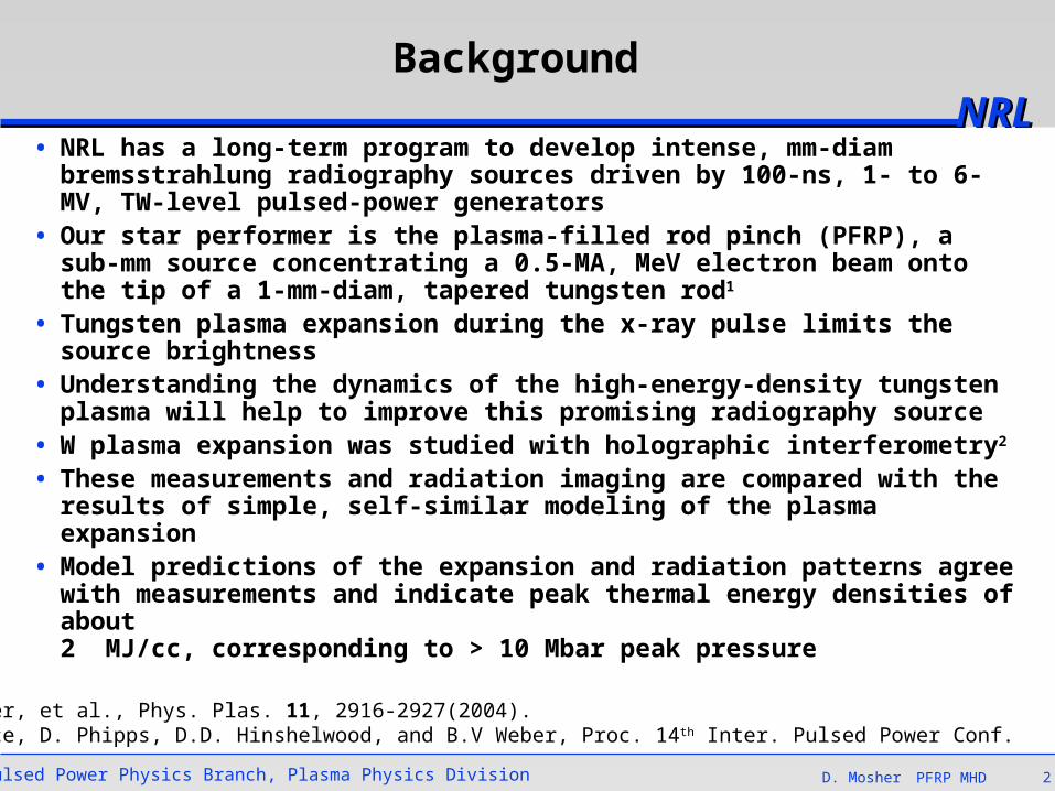
• NRL has a long-term program to develop intense, mm-diam bremsstrahlung radiography sources driven by 100-ns, 1- to 6-MV, TW-level pulsed-power generators
• Our star performer is the plasma-filled rod pinch (PFRP), a sub-mm source concentrating a 0.5-MA, MeV electron beam onto the tip of a 1-mm-diam, tapered tungsten rod1
• Tungsten plasma expansion during the x-ray pulse limits the source brightness
• Understanding the dynamics of the high-energy-density tungsten plasma will help to improve this promising radiography source
• W plasma expansion was studied with holographic interferometry2
• These measurements and radiation imaging are compared with the results of simple, self-similar modeling of the plasma expansion
• Model predictions of the expansion and radiation patterns agree with measurements and indicate peak thermal energy densities of about2 MJ/cc, corresponding to > 10 Mbar peak pressure
1B.V. Weber, et al., Phys. Plas. 11, 2916-2927(2004).2D.M. Ponce, D. Phipps, D.D. Hinshelwood, and B.V Weber, Proc. 14 th Inter. Pulsed Power Conf.
Pulsed Power Physics Branch, Plasma Physics Division D. Mosher 3PFRP MHD
NRLNRLPFRP operation on Gamble II
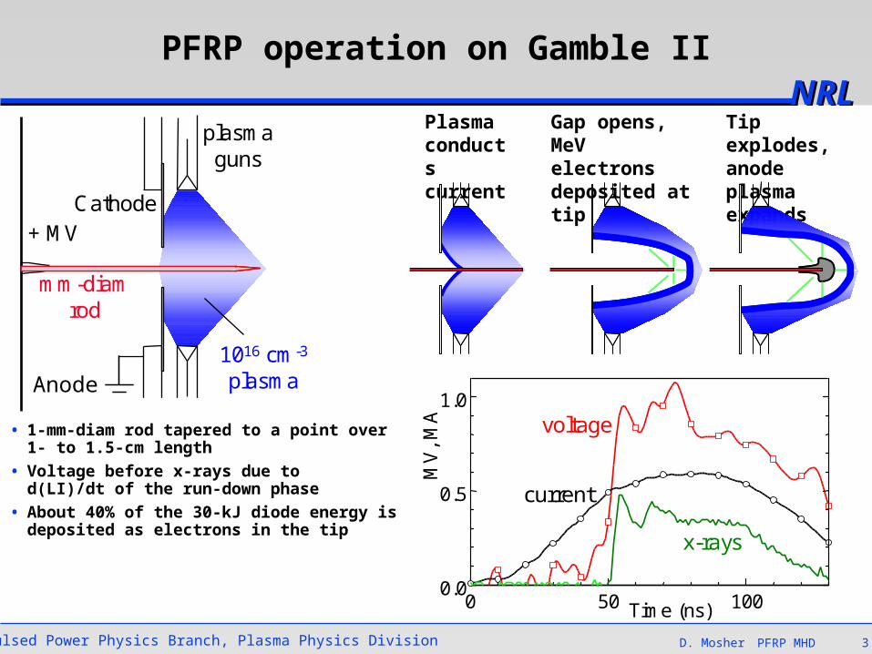
• 1-mm-diam rod tapered to a point over 1- to 1.5-cm length
• Voltage before x-rays due tod(LI)/dt of the run-down phase
• About 40% of the 30-kJ diode energy is deposited as electrons in the tip
Plasmaconductscurrent
Gap opens,MeV electronsdeposited at tip
Tip explodes, anode plasma expands
0 50 1000.0
0.5
1.0
1.5Shot 7956
MV
, M
A
Time (ns)0
25
50
75
x-rays
current
voltage
+ MV
plasmaguns
mm-diamrod
Cathode
1016 cm-3
plasmaAnode
Pulsed Power Physics Branch, Plasma Physics Division D. Mosher 4PFRP MHD
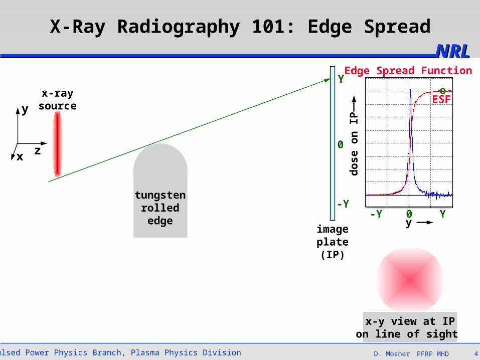
NRLNRLX-Ray Radiography 101: Edge Spread
x z
y
x-y view at IPon line of sight
tungstenrollededge
x-raysource
imageplate(IP)
0
2
4
6
8
10
0 4 8 12 16
LSV (2.0e01) ESVcor (1.0e01)9127
ESF
y
do
se o
n IP
Edge Spread FunctionY
0
-Y-Y 0 Y
Pulsed Power Physics Branch, Plasma Physics Division D. Mosher 5PFRP MHD
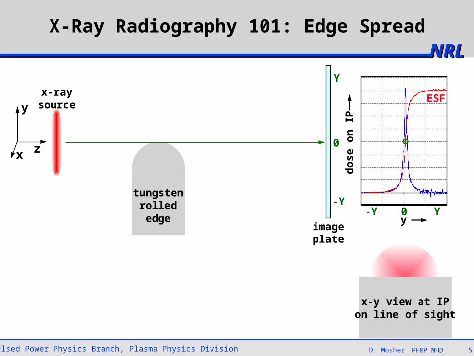
NRLNRLX-Ray Radiography 101: Edge Spread
x z
y
x-y view at IPon line of sight
tungstenrollededge
x-raysource
imageplate
Y
0
-Y0
2
4
6
8
10
0 4 8 12 16
LSV (2.0e01) ESVcor (1.0e01)9127
ESF
do
se o
n IP
-Y 0 Yy
Pulsed Power Physics Branch, Plasma Physics Division D. Mosher 6PFRP MHD
NRLNRLX-Ray Radiography 101: Edge Spread
x z
y
x-y view at IPon line of sight
tungstenrollededge
x-raysource
imageplate
Y
0
-Y0
2
4
6
8
10
0 4 8 12 16
LSV (2.0e01) ESVcor (1.0e01)9127
ESF
do
se o
n IP
-Y 0 Yy
Pulsed Power Physics Branch, Plasma Physics Division D. Mosher 7PFRP MHD
NRLNRLX-Ray Radiography 101: Line Spread
• LSF(y)dy is a measure of x-ray energy emitted in a thin strip along x
• Source radial distribution:Point Spread Function PSF(r)
• PSF recovered from LSF byAbel inversion
x z
y
x-raysourcePSF(r)
y 22 yr
rdr)r(PSF2ESF
dy
d)y(LSF
0
2
4
6
8
10
0 4 8 12 16
LSV (2.0e01) ESVcor (1.0e01)9127
ESF
LSF
do
se o
n IP
Line Spread Function
y
x-y view
Pulsed Power Physics Branch, Plasma Physics Division D. Mosher 8PFRP MHD
NRLNRL
The plasma filled rod pinch diode on GAMBLE II has a line spread with two distinct length scales
• 0.4-mm FWHM characteristic of conical-rod-tip emission
• Few-mm "wings" associated with tungsten plasma expansion during the x-ray pulse
• X-ray pinhole images and interferometry show plasma expansion at the rod tip
• Use hydro-expansion model to confirm the wing feature
cathode
-0.1
0.1
0.3
0.5
0.7
0.9
1.1
-3 -2 -1 0 1 2 3position (mm)
line
sp
rea
d (
LS
)
experiment
conical tip
Line Spread for 1-mm-DiamTapered W Rod
Interferogram and Rod Shadowat the End of the X-Ray Pulse
Pulsed Power Physics Branch, Plasma Physics Division D. Mosher 9PFRP MHD
NRLNRL
The axial line spread measures the x-ray intensity emitted along the rod
• The axial line spread is a measure of electron-beam heating vs z
• Beam heating near the rod tip has a FWHM of about 4 mm
• This axial heating profile is used in the model to drive tungsten-plasma expansion
• Hydro-expansion model predictions are compared to– 2D, time-dependent interferometry– the measured time-integrated LSF
• Agreement with these measurements will indicate that the tungsten plasma parameters are reasonable and in the HED regime
x z
y
image plate
rollededge
0.00.2
0.40.60.8
1.0
0 10 20 30 40axial position (mm)
Edge Spread
Line Spread
pinhole image
Pulsed Power Physics Branch, Plasma Physics Division D. Mosher 10PFRP MHD
NRLNRL
dt)t,r(P~)r(P
P)t,r(n~)t,r(P
dt
dR
2
NmdtR2TP)t(E
Rm
kT)Z1(2
dt
Rd
)0(Rm
N
R/rexp)t(R
N)t,r(n
end
0brbr
4/5hbr
2W
t
0
4hint
W2
2
W2
W
222
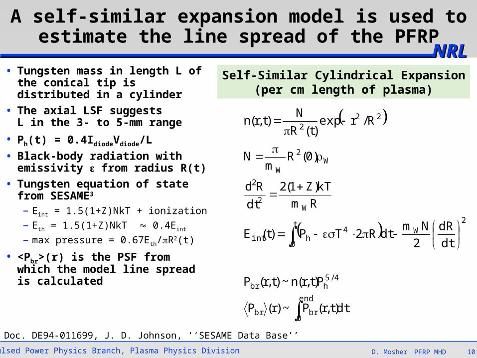
A self-similar expansion model is used to estimate the line spread of the PFRP
• Tungsten mass in length L of the conical tip is distributed in a cylinder
• The axial LSF suggestsL in the 3- to 5-mm range
• Ph(t) = 0.4IdiodeVdiode/L
• Black-body radiation with emissivity from radius R(t)
• Tungsten equation of statefrom SESAME3
– Eint = 1.5(1+Z)NkT + ionization
– Eth = 1.5(1+Z)NkT 0.4Eint
– max pressure = 0.67Eth/R2(t)
• <Pbr>(r) is the PSF from which the model line spread is calculated
Self-Similar Cylindrical Expansion(per cm length of plasma)
3NTIS Doc. DE94-011699, J. D. Johnson, ‘‘SESAME Data Base’’
Pulsed Power Physics Branch, Plasma Physics Division D. Mosher 11PFRP MHD
NRLNRL
0.0E+00
5.0E+03
1.0E+04
1.5E+04
2.0E+04
2.5E+04
3.0E+04
0 20 40 60 80t (ns)
en
erg
y (J
/cm
)
heating
kinetic
internal
radiation
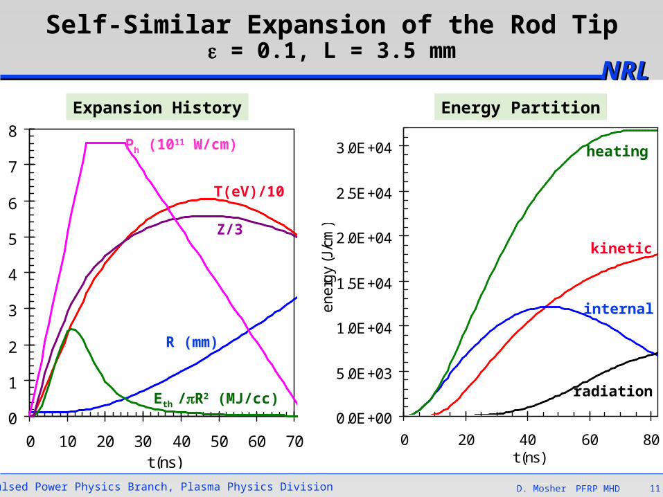
Self-Similar Expansion of the Rod Tip = 0.1, L = 3.5 mm
Energy PartitionExpansion History
0
1
2
3
4
5
6
7
8
0 10 20 30 40 50 60 70t (ns)
Eth /R2 (MJ/cc)
R (mm)
T(eV)/10
Z/3
Ph (1011 W/cm)
Pulsed Power Physics Branch, Plasma Physics Division D. Mosher 12PFRP MHD
NRLNRL
0.0
0.2
0.4
0.6
0.8
1.0
0.0 0.5 1.0 1.5r (mm)
<P
br>
(r)
-0.1
0.1
0.3
0.5
0.7
0.9
1.1
1.3
1.5
-3 -2 -1 0 1 2 3position (mm)
line
sp
rea
d
experiment
L = 3 mm
L = 4 mm
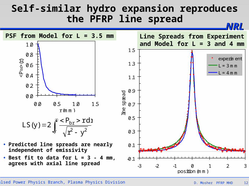
Self-similar hydro expansion reproduces the PFRP line spread
• Predicted line spreads are nearly independent of emissivity
• Best fit to data for L = 3 - 4 mm,agrees with axial line spread
PSF from Model for L = 3.5 mm Line Spreads from Experimentand Model for L = 3 and 4 mm
y 22
br
yr
rdrP2)y(LS
Pulsed Power Physics Branch, Plasma Physics Division D. Mosher 13PFRP MHD
NRLNRL
0.0
0.2
0.4
0.6
0.8
0.0 0.2 0.4 0.6 0.8 1.0 1.2 1.4 1.6z(cm)
R (
cm)
0
10
20
30
40
50
60
70
T (
eV
)
R, 40 ns
R, 70 ns
R, 110 ns
T, 40 ns
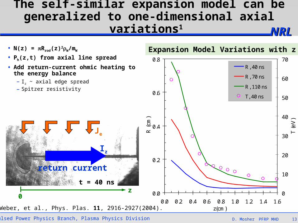
The self-similar expansion model can be generalized to one-dimensional axial variations1
• N(z) = Rrod(z)2W/mW
• Ph(z,t) from axial line spread
• Add return-current ohmic heating to the energy balance– Iz ~ axial edge spread
– Spitzer resistivity
Expansion Model Variations with z
1B.V. Weber, et al., Phys. Plas. 11, 2916-2927(2004).
Je
Iz
return current
t = 40 nsz
0
Pulsed Power Physics Branch, Plasma Physics Division D. Mosher 14PFRP MHD
NRLNRL
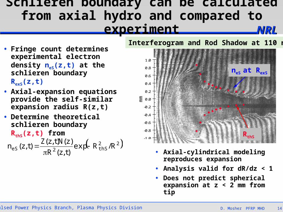
• Fringe count determines experimental electron density neS(z,t) at the schlieren boundary RexS(z,t)
• Axial-expansion equations provide the self-similar expansion radius R(z,t)
• Determine theoretical schlieren boundary RthS(z,t) from
Schlieren boundary can be calculated from axial hydro and compared to experiment
22thS2eS R/Rexp
)t,z(R
)z(N)t,z(Z)t,z(n
mm
neS at RexS
RthS -1.0
-0.8
-0.6
-0.4
-0.2
0.0
0.2
0.4
0.6
0.8
1.0
0.0 0.2 0.4 0.6 0.8 1.0 1.2 1.4 1.6 1.8 2.0
Interferogram and Rod Shadow at 110 ns
• Axial-cylindrical modeling reproduces expansion
• Analysis valid for dR/dz < 1
• Does not predict spherical expansion at z < 2 mm from tip
Pulsed Power Physics Branch, Plasma Physics Division D. Mosher 15PFRP MHD
NRLNRLConclusions
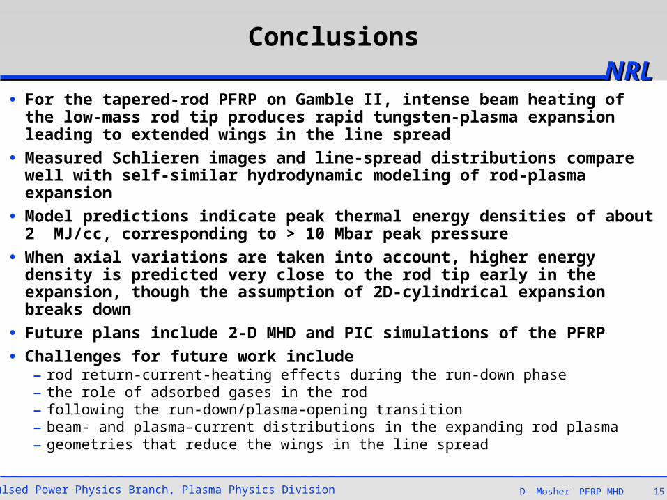
• For the tapered-rod PFRP on Gamble II, intense beam heating of the low-mass rod tip produces rapid tungsten-plasma expansion leading to extended wings in the line spread
• Measured Schlieren images and line-spread distributions compare well with self-similar hydrodynamic modeling of rod-plasma expansion
• Model predictions indicate peak thermal energy densities of about2 MJ/cc, corresponding to > 10 Mbar peak pressure
• When axial variations are taken into account, higher energy density is predicted very close to the rod tip early in the expansion, though the assumption of 2D-cylindrical expansion breaks down
• Future plans include 2-D MHD and PIC simulations of the PFRP
• Challenges for future work include– rod return-current-heating effects during the run-down phase– the role of adsorbed gases in the rod– following the run-down/plasma-opening transition– beam- and plasma-current distributions in the expanding rod plasma– geometries that reduce the wings in the line spread


![[Solutions] Introduction to Plasma Physics and Controlled Fusion Plasma Physics](https://img.pdfslide.net/doc/110x75/55cf9d44550346d033ace210/solutions-introduction-to-plasma-physics-and-controlled-fusion-plasma-physics.jpg)