Embed Size (px)
Citation preview

an Astec company
MCP
HYD
RA
ULIC
PU
LV
ER
IZER
S
150-903401/2009
OWNER’S MANUALOPERATION, SERVICE & PARTS
FOR MCP800, MCP910, MCP1000
OWNER’S MANUAL

www.rockbreaker.com22

Pulverizer Owner’s Manual 33
CONTENTS
Sizing the Pulverizer
Typical Hydraulic Circuits
Speed Valve Schematics
General Information
Safety
Installation
Disassembly
Operation
Maintenance
Warranty
MCP800 Parts
MCP910 Parts
MCP1000 Parts
Blade Bolt Specifications
4
5
7
9
13
20
25
27
28
47
48
59
69
77
www.rockbreaker.com44
SIZING THE PULVERIZER
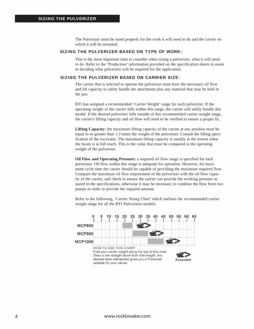
The Pulverizer must be sized properly for the work it will need to do and the carrier on which it will be mounted.
This is the most important item to consider when sizing a pulverizer, what it will need to do. Refer to the ‘Production’ information provided on the specification sheets to assist in deciding what pulverizer will be required for the application.
The carrier that is selected to operate the pulverizer must have the necessary oil flow and lift capacity to safety handle the attachment plus any material that may be held in the jaw.
BTI has assigned a recommended ‘Carrier Weight’ range for each pulverizer. If the operating weight of the carrier falls within this range, the carrier will safely handle this model. If the desired pulverizer falls outside of this recommended carrier weight range, the carrier's lifting capacity and oil flow will need to be verified to ensure a proper fit..
Lifting Capacity: the maximum lifting capacity of the carrier at any position must beequal to or greater than 1.3 times the weight of the pulverizer. Consult the lifting speci-fication of the excavator. The maximum lifting capacity is usually at the lowest when the boom is at full reach. This is the value that must be compared to the operating weight of the pulverizer.
Oil Flow and Operating Pressure: a required oil flow range is specified for eachpulverizer. Oil flow within this range is adequate for operation. However, for maxi-mum cycle time the carrier should be capable of providing the maximum required flow. Compare the maximum oil flow requirement of the pulverizer with the oil flow capac-ity of the carrier, and check to ensure the carrier can provide the working pressure as stated in the specifications, otherwise it may be necessary to combine the flow from two pumps in order to provide the required amount.
Refer to the following, ‘Carrier Sizing Chart’ which outlines the recommended carrier weight range for all the BTI Pulverizers models.
SIZING THE PULVERIZER BASED ON TYPE OF WORK:
SIZING THE PULVERIZER BASED ON CARRIER SIZE:

Pulverizer Owner’s Manual 55
TYPICAL HYDRAULIC CIRCUITS
CARRIER WITH AUXILIARY CIRCUIT:
Hydraulic Demolition Attachments require hydraulic flow and pressure in two directions (bidirectional flow). They need oil to extend and retract hydraulic cylin-ders.
The MCP series Hydraulic Pulverizer and SH series Shear use a single hydrau-lic cylinder. The CR series Hydraulic Crusher and MP Multi-Processors use two hydraulic cylinders (see Fig.1).
Some Demolition Attachments require a Rotate Circuit to operate a hydraulic motor (see Fig.2). Again, this will need to be bidirectional and have adjustable flow and port relief settings.
The carrier will quite often be equipped with an auxiliary control valve, which can be used to control the supply of oil.
Fig.1 Carrier with Auxiliary Circuit
INT
RO
DU
CT
ION
SA
FET
YIN
STA
LLAT
ION
OP
ER
AT
ION
MA
INT
EN
AN
CE
WA
RR
AN
TY
PAR
TS

www.rockbreaker.com66
TYPICAL HYDRAULIC CIRCUITS
If the carrier is not equipped with an auxiliary control valve, an additional circuit must be added using a priority flow control and/or a bidirectional valve. Please consult your BTI service representative for more details.
Fig.3 Carrier’s without Auxiliary Circuit
CARRIER WITHOUT AUXILIARY CIRCUIT:
Pulverizer Owner’s Manual 7
SPEED VALVE SCHEMATIC
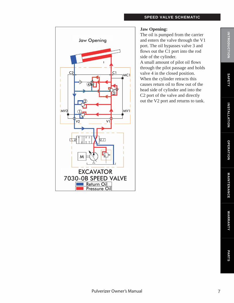
Jaw Opening:The oil is pumped from the carrier and enters the valve through the V1 port. The oil bypasses valve 3 and fl ows out the C1 port into the rod side of the cylinder. A small amount of pilot oil fl ows through the pilot passage and holds valve 4 in the closed position. When the cylinder retracts this causes return oil to fl ow out of the head side of cylinder and into the C2 port of the valve and directly out the V2 port and returns to tank.
INT
RO
DU
CT
ION
SA
FET
YIN
STA
LLAT
ION
OP
ER
AT
ION
MA
INT
EN
AN
CE
WA
RR
AN
TY
PAR
TS

www.rockbreaker.com8
SPEED VALVE SCHEMATIC
Jaw Closing With No Load:Oil is pumped from the carrier into the V2 port of the speed valve. Oil passes directly through to the port C2 and enters the head side of the cylinder. A small amount of this oil fl ows through the pilot passage and holds valve 4 in the open position. This causes the oil fl owing out of the rod side of the cylin-der to fl ow through valve 4 to join the input oil fl owing out C2 port and right back in the head side of the cylinder causing it to close faster. AS long as the oil pressure stays below the set pressure, valve 3 will stay closed and no oil will be returned to the tank.
Jaw Closing Under Load:Oil is pumped from the carrier into the V2 port of the valve. Oil passes directly through the valve and out the C2 port into the head side of the cylinder. A small amount of this oil fl ows through the pilot passage and because the cylinder is under load, the oil pressure raises to above set pressure which causes valve 3 to open. The pressure stops fl ow of oil back to the head side of the cylinder and the oil from the rod side of the cylinder returns to tank. This causes the jaw to close slower but with more closing power.
Cross Over Port Relief Protection: Valves 1 and 2 are cross over port relief protection valves to protect the circuit if the jaw was to be forced open or closed. If the jaw is forced either way, the pressure will rise. Once the oil in either side rises above the set pressure, the valve will open, relieving the pressure and returning some oil to tank.

Pulverizer Owner’s Manual 99
GENERAL INFORMATION
MODEL WEIGHT WORKINGPRESSURE
OIL FLOW
CYLINDEROUTPUT
MAX DIA. TO BE CUT
A B C D
MCP800
MCP910
MCP1000
4510 lbs.(2050 kg.)
6270 lbs.(2850 kg.)
8360 lbs.(3800 kg.)
4060-4640 psi(280-320 bar)
45-58 gal US/min(180-220 l/min)
58-74 gal US/min(220-280 l/min)
74-84 gal US/min(280-320 l/min)
145 tons
157 tons
197 tons
2.125 in(55 mm)
2.375 in(60 mm)
2.5 in(65 mm)
33.5 in(850 mm)
39.4 in(1000 mm)
43.3 in(1100 mm)
81.5 in(2070 mm)
94.5 in(2900 mm)
105.3 in(2675 mm)
21.7 in(550 mm)
23.8 in(605 mm)
30.0 in(660 mm)
27 in(685 mm)
28.75 in(730 mm)
35.4 in(900 mm)
4060-4640 psi(280-320 bar)
4060-4640 psi(280-320 bar)
JAW OPENING
HEIGHT WIDTH JAW DEPTH
INT
RO
DU
CT
ION
SA
FET
YIN
STA
LLAT
ION
OP
ER
AT
ION
MA
INT
EN
AN
CE
WA
RR
AN
TY
PAR
TS
www.rockbreaker.com1010
GENERAL INFORMATION
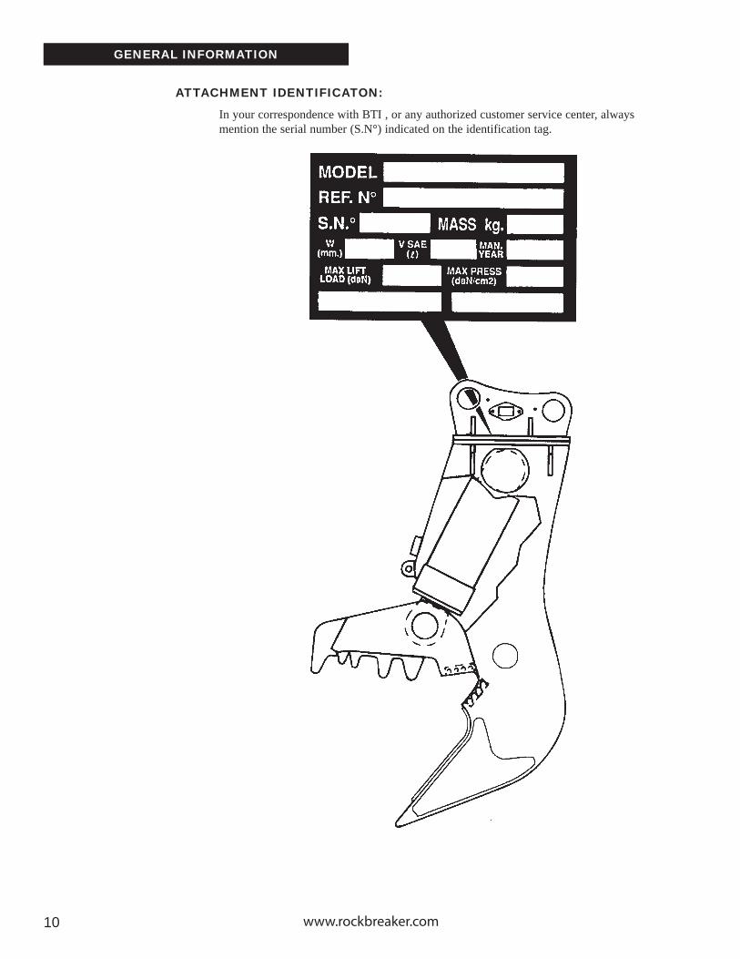
In your correspondence with BTI , or any authorized customer service center, always mention the serial number (S.N°) indicated on the identification tag.
ATTACHMENT IDENTIFICATON:

Pulverizer Owner’s Manual 1111
GENERAL INFORMATION
DECAL LOCATIONS:
1
2
3
5 46
65 FT
Read the Operator's Manual
High Pressure Fluid. Injection into Body
Consult Owner's Manual for Service Procedures
Keep Safety Distance of 20M - 65 Feet
Beware of Flying Objects.
1
2
3
4
5
6 Lift Point
INT
RO
DU
CT
ION
SA
FET
YIN
STA
LLAT
ION
OP
ER
AT
ION
MA
INT
EN
AN
CE
WA
RR
AN
TY
PAR
TS
www.rockbreaker.com1212
SAFETY
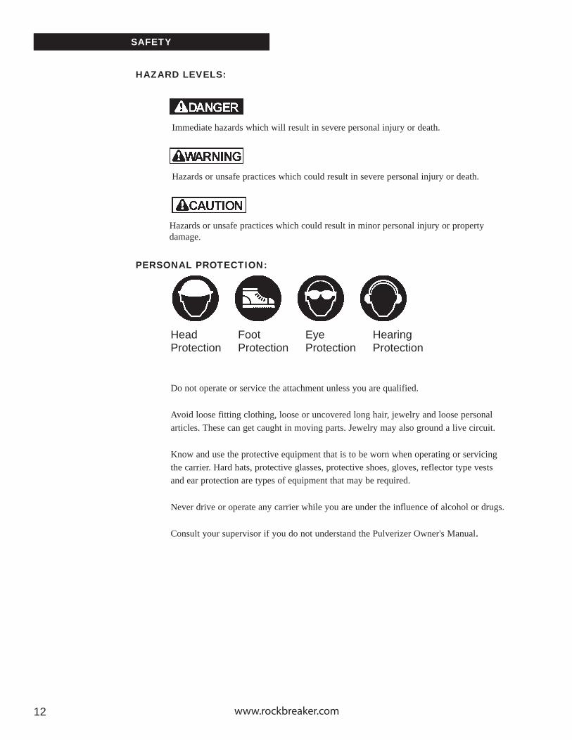
HAZARD LEVELS:
Immediate hazards which will result in severe personal injury or death.
Hazards or unsafe practices which could result in severe personal injury or death.
Hazards or unsafe practices which could result in minor personal injury or property damage.
PERSONAL PROTECTION:
Head Foot Eye HearingProtection Protection Protection Protection
Do not operate or service the attachment unless you are qualified.
Avoid loose fitting clothing, loose or uncovered long hair, jewelry and loose personal articles. These can get caught in moving parts. Jewelry may also ground a live circuit.
Know and use the protective equipment that is to be worn when operating or servicing the carrier. Hard hats, protective glasses, protective shoes, gloves, reflector type vests and ear protection are types of equipment that may be required.
Never drive or operate any carrier while you are under the influence of alcohol or drugs.
Consult your supervisor if you do not understand the Pulverizer Owner's Manual.
Pulverizer Owner’s Manual 1313
SAFETY
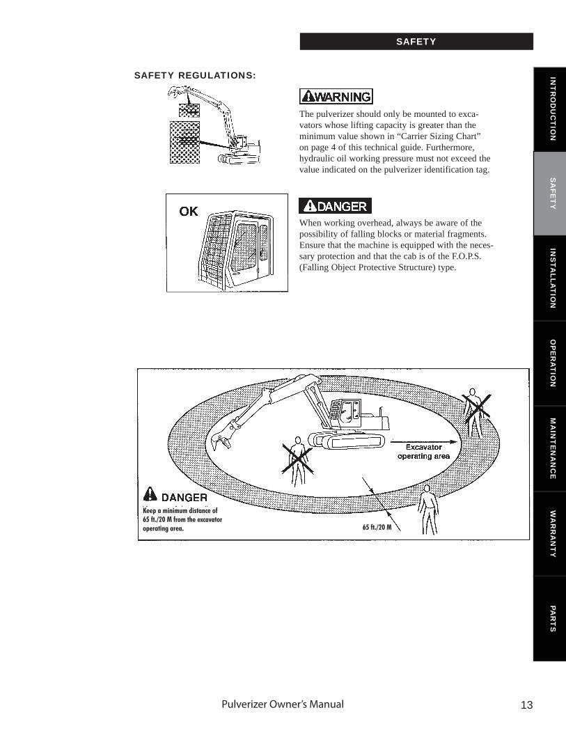
The pulverizer should only be mounted to exca-vators whose lifting capacity is greater than the minimum value shown in “Carrier Sizing Chart” on page 4 of this technical guide. Furthermore, hydraulic oil working pressure must not exceed the value indicated on the pulverizer identification tag.
When working overhead, always be aware of the possibility of falling blocks or material fragments. Ensure that the machine is equipped with the neces-sary protection and that the cab is of the F.O.P.S. (Falling Object Protective Structure) type.
SAFETY REGULATIONS:
Keep a minimum distance of 65 ft./20 M from the excavator operating area. 65 ft./20 M
INT
RO
DU
CT
ION
SA
FET
YIN
STA
LLAT
ION
OP
ER
AT
ION
MA
INT
EN
AN
CE
WA
RR
AN
TY
PAR
TS
www.rockbreaker.com1414
SAFETY
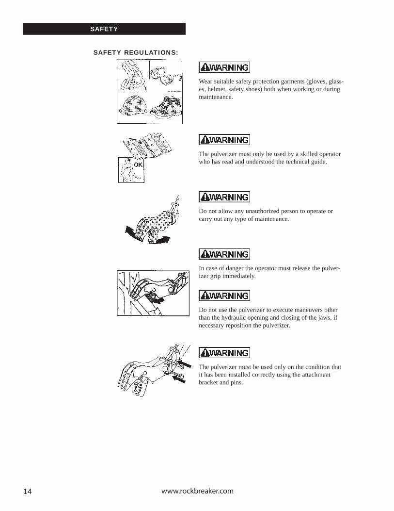
Wear suitable safety protection garments (gloves, glass-es, helmet, safety shoes) both when working or during maintenance.
The pulverizer must only be used by a skilled operator who has read and understood the technical guide.
Do not allow any unauthorized person to operate or carry out any type of maintenance.
In case of danger the operator must release the pulver-izer grip immediately.
Do not use the pulverizer to execute maneuvers other than the hydraulic opening and closing of the jaws, if necessary reposition the pulverizer.
The pulverizer must be used only on the condition that it has been installed correctly using the attachment bracket and pins.
SAFETY REGULATIONS:

Pulverizer Owner’s Manual 1515
SAFETY
The pulverizer must not be used for lifting, hammering, or transporting any type of material whatsoever.
Should the demolition pulverizer accidentally become entangled in the reinforcement bars of the structure being demolished, make sure to free it before proceed-ing with the demolition work.
Do not use the pulverizer for lifting or for extracting pieces driven in the ground.
Do not begin demolition work from lower parts of a structure as this could cause the upper part to collapse.
Do not use the pulverizer to hammer against the struc-ture being demolished.
SAFETY REGULATIONS: INT
RO
DU
CT
ION
SA
FET
YIN
STA
LLAT
ION
OP
ER
AT
ION
MA
INT
EN
AN
CE
WA
RR
AN
TY
PAR
TS
www.rockbreaker.com1616
SAFETY
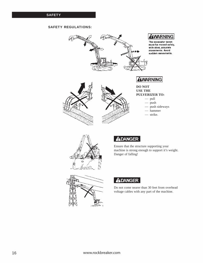
DO NOT USE THEPULVERIZER TO:
— pull— push— push sideways— hammer— strike.
SAFETY REGULATIONS:
Ensure that the structure supporting your machine is strong enough to support it’s weight. Danger of falling!
Do not come nearer than 30 feet from overhead voltage cables with any part of the machine.
Pulverizer Owner’s Manual 1717
SAFETY
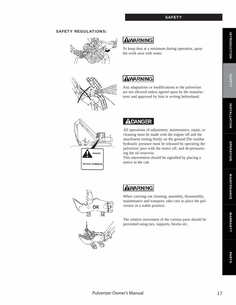
To keep dust at a minimum during operation, spray the work area with water.
Any adaptations or modifications to the pulverizer are not allowed unless agreed upon by the manufac-turer and approved by him in writing beforehand.
SAFETY REGULATIONS:
All operations of adjustment, maintenance, repair, or cleaning must be made with the engine off and the attachment resting firmly on the ground.The residue hydraulic pressure must be released by operating the pulverizer jaws with the motor off, and de-pressuriz-ing the oil reservoir.This intervention should be signalled by placing a notice in the cab.
When carrying out cleaning, assembly, disassembly, maintenance and transport, take care to place the pul-verizer in a stable position.
The relative movement of the various parts should be prevented using ties, supports, blocks etc.
INT
RO
DU
CT
ION
SA
FET
YIN
STA
LLAT
ION
OP
ER
AT
ION
MA
INT
EN
AN
CE
WA
RR
AN
TY
PAR
TS

www.rockbreaker.com1818
SAFETY
SAFETY REGULATIONS:
For hydraulic connections, use only hydraulic hoses and fittings that conform to standards SAE J5l7 or DIN 20066 for the specified pressure. Failing to observe the above could jeopardize the safe functioning of the pul-verizer.
Always visually check the condition of the hoses daily for damage. If a hose becomes damaged, replace it immediately.Any suspected leakages should be traced using pieces of paper or carton paper, never use your hand. High pres-sure fluid will pierce the skin.
The oil can reach high temperatures. Before carrying out any cleaning or maintenance, wait for the oil to cool.
The cutters can be very hot, before carrying out any work on the cutters, wait for them to cool down.
Do not cut reinforcement bars with diameter greater than the value shown in table on page 7.
Use only original BTI spare parts.
The screws connecting the joint and the pulverizer body must be tightened using a torque wrench. See Chart.

Pulverizer Owner’s Manual 1919
SAFETY
TRANSPORTING:The pulverizer may be shipped on a skid or in a crate, depending on the destination and the customer requirement.
For lifting and transporting to the installation site, use adequate sling ropes or a fork lift. Note component weight on identification tag, or on outside of crate. Use proper slinging procedures.A copy of the Owners Manual must be kept in the machine cab for the use by the operator. If additional copies are required, contact your BTI representative.
Lift the pulverizer with sling ropes of suitable capaci-ty using the correct lift points indicated by the stickers and position it on two wooden joists approximately 12 inches high.
INT
RO
DU
CT
ION
SA
FET
YIN
STA
LLAT
ION
OP
ER
AT
ION
MA
INT
EN
AN
CE
WA
RR
AN
TY
PAR
TS

www.rockbreaker.com20
FITTING TO THE EXCAVATOR
20
The hydraulic Pulverizer is designed to mount as a third member in place of the bucket.
Before mounting the attachment to the machine, we must check that the machine will be stable when working, and that the lifting capacity of the excavator is sufficient to meet essential safety requirements and prevent the excavator from turning over.To do this, we must determine that:
- the weight of the attachment (“P”),
- multiplied times an attachment correction factor (“K”),
- is less than or equal to the Minimum Lifting Capacity (“LC”)
P = Attachment Weight
K = 1.2 for Pulverizers
LC min. = Minimum excavator Lifting Capacity in the configuration considered through 360 ° and on the bucket pivot, taken from the technical data of the excavator or supplied by the excavator manufacturer. Calculated as indicated in standards ISO 10567-1992. Use Chart on page 4 for guide line.
To avoid subjecting the attachment to excessive stresses, do not fit the pulverizer to excavators with an operating mass exceeding the values shown in the table on page 4. For installations which do not comply with the criteria shown, contact your BTI repre-sentative to carry out any verification necessary to ensure the safety of the combination.
NOTE: If the lifting capacity is calculated according to the standards SAE/Std. N. J1097 or DIN 15019 to obtain the LC minimum, the weight of the bucket should be added).
NOTE: This condition guarantees the stability of the excavator ONLY when working on a firm, level, supported horizontal surface.
MATCHING ATTACHMENT TO MACHINE:

Pulverizer Owner’s Manual 2121
CONTROLS
Before using the pulverizer on the excavator, ensure that the hydraulic controls for jaw opening and closing respect the following requirements.
All controls should be:
– Clearly visible, separate and suitably marked.
– Arranged so as to provide a guarantee of clear, fast and safe operation.
– Designed to ensure that the machine’s movements are coherent to the command action given.
– Designed and protected to ensure that no action can take place without an inten-tional command.
– Arranged so that the operator can ensure that no person is within the danger area.
– Fitted with a “dead man control” which when released cuts off the energy supply to the drive parts and brings to a state of rest all moving parts.
It is advisable to provide a clearly marked device in the control circuit which enables the circuit to be isolated from its source of energy, and discharges the residue oil pres-sure. This device overcomes the risk of high pressure oil jets being present during dis-mantling or maintenance.
In the absence of this device, the residue oil pressure should be vented by repeated opening and closing actions with the engine turned off. Release reservoir pressure by opening the cap. This operation should be carried out each time that an intervention for service or maintenance is necessary.
To avoid undesired movements should the pressure lines be ruptured, install a non-return valve to block all movements of the excavator upon a fall in line pressure.
CONTROL DEVICES:
SAFETY
INT
RO
DU
CT
ION
SA
FET
YIN
STA
LLAT
ION
OP
ER
AT
ION
MA
INT
EN
AN
CE
WA
RR
AN
TY
PAR
TS
www.rockbreaker.com22
INSTALLATION
22
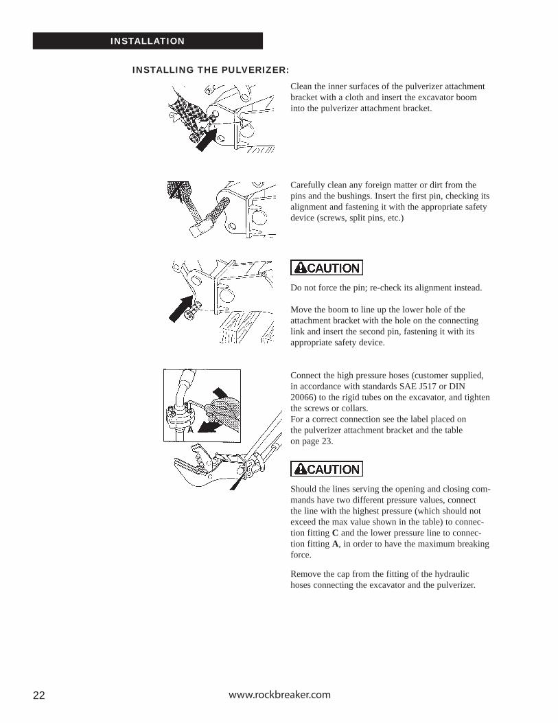
Clean the inner surfaces of the pulverizer attachment bracket with a cloth and insert the excavator boom into the pulverizer attachment bracket.
Carefully clean any foreign matter or dirt from the pins and the bushings. Insert the first pin, checking its alignment and fastening it with the appropriate safety device (screws, split pins, etc.)
Do not force the pin; re-check its alignment instead.
Move the boom to line up the lower hole of the attachment bracket with the hole on the connecting link and insert the second pin, fastening it with its appropriate safety device. Connect the high pressure hoses (customer supplied, in accordance with standards SAE J517 or DIN 20066) to the rigid tubes on the excavator, and tighten the screws or collars. For a correct connection see the label placed on the pulverizer attachment bracket and the table on page 23.
Should the lines serving the opening and closing com-mands have two different pressure values, connect the line with the highest pressure (which should not exceed the max value shown in the table) to connec-tion fitting C and the lower pressure line to connec-tion fitting A, in order to have the maximum breaking force.
Remove the cap from the fitting of the hydraulic hoses connecting the excavator and the pulverizer.
INSTALLING THE PULVERIZER:

Pulverizer Owner’s Manual 2323
Make sure that the hose fittings are perfectly clean and dust-free. Any foreign matter (sand, gravel, dust) in the fittings may cause seizure of the pulverizer hydraulic cylinders.
INSTALLING THE PULVERIZER:
INSTALLATION
FITTING MARKING
A CPULVERIZER
OPENINGPULVERIZER
CLOSING
PULVERIZERMODEL
MCP800
MCP910
MCP100
RIGID TUBEDiameter X Thickness
1 15/16” X 1/8”(35mm X 4mm)
1 3/4” X 5/16”(42mm X 5mm)
1 3/4” X 5/16”(42mm X 5mm)
TYPE OF FITTING
1” SAE 6000 psiSplit Flange
Code 62
1 1/4” SAE 6000 psiSplit Flange
Code 62
1 1/4” SAE 6000 psiSplit Flange
Code 62
MAXIMUMPRESSURE
4640 psi(320 bar)
4640 psi(320 bar)
4640 psi(320 bar)
Start up the excavator and turn up the hydraulic pres-sure slowly in order to avoid sudden movements until reaching the maximum working pressure of 5075 psi (350 bar). Specifications can be verified by checking identification tag.
With the motor idling, open the pulverizer one quar-ter and re-close, then open halfway and re-close, then open 3/4 and re-close, finally open completely and re-close.
Open and close the pulverizer 5 or 6 times making sure there is no leakage in the hydraulic system.
INT
RO
DU
CT
ION
SA
FET
YIN
STA
LLAT
ION
OP
ER
AT
ION
MA
INT
EN
AN
CE
WA
RR
AN
TY
PAR
TS
www.rockbreaker.com2424
INSTALLATION
READY FOR OPERATION:
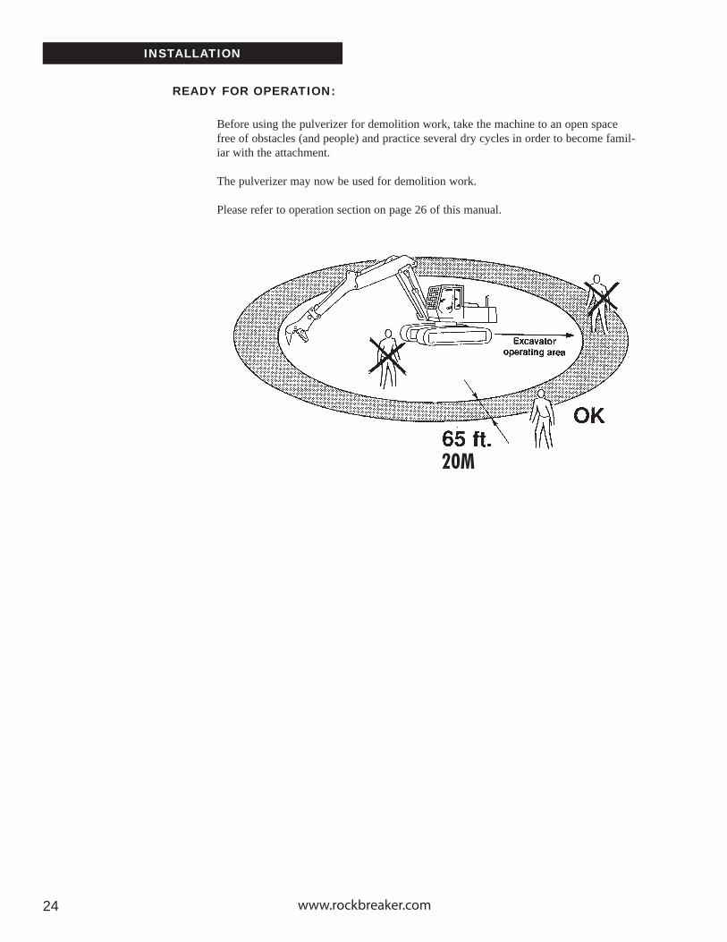
Before using the pulverizer for demolition work, take the machine to an open space free of obstacles (and people) and practice several dry cycles in order to become famil-iar with the attachment.
The pulverizer may now be used for demolition work.
Please refer to operation section on page 26 of this manual.
20M

Pulverizer Owner’s Manual 2525
DISASSEMBLY
At the end of the job, perform the following before removing the pulverizer and putting it away:
With the excavator engine running, open the pul-verizer so that the piston rod slides completely into the hydraulic cylinder.
Lay the pulverizer horizontally on two wooden blocks placed on the ground.
Put the excavator in its resting position and turn the engine off.
Check that no residue oil pressure remains in the oil circuit. The residue hydraulic pressure must be discharged by operating the controls several times with the motor off and de-pressurizing the oil reservoir.
Loosen the fittings on the whip hoses and seal all hydraulic ports with protective caps.
STOPPING & DISASSEMBLY: INT
RO
DU
CT
ION
SA
FET
YIN
STA
LLAT
ION
OP
ER
AT
ION
MA
INT
EN
AN
CE
WA
RR
AN
TY
PAR
TS
www.rockbreaker.com2626
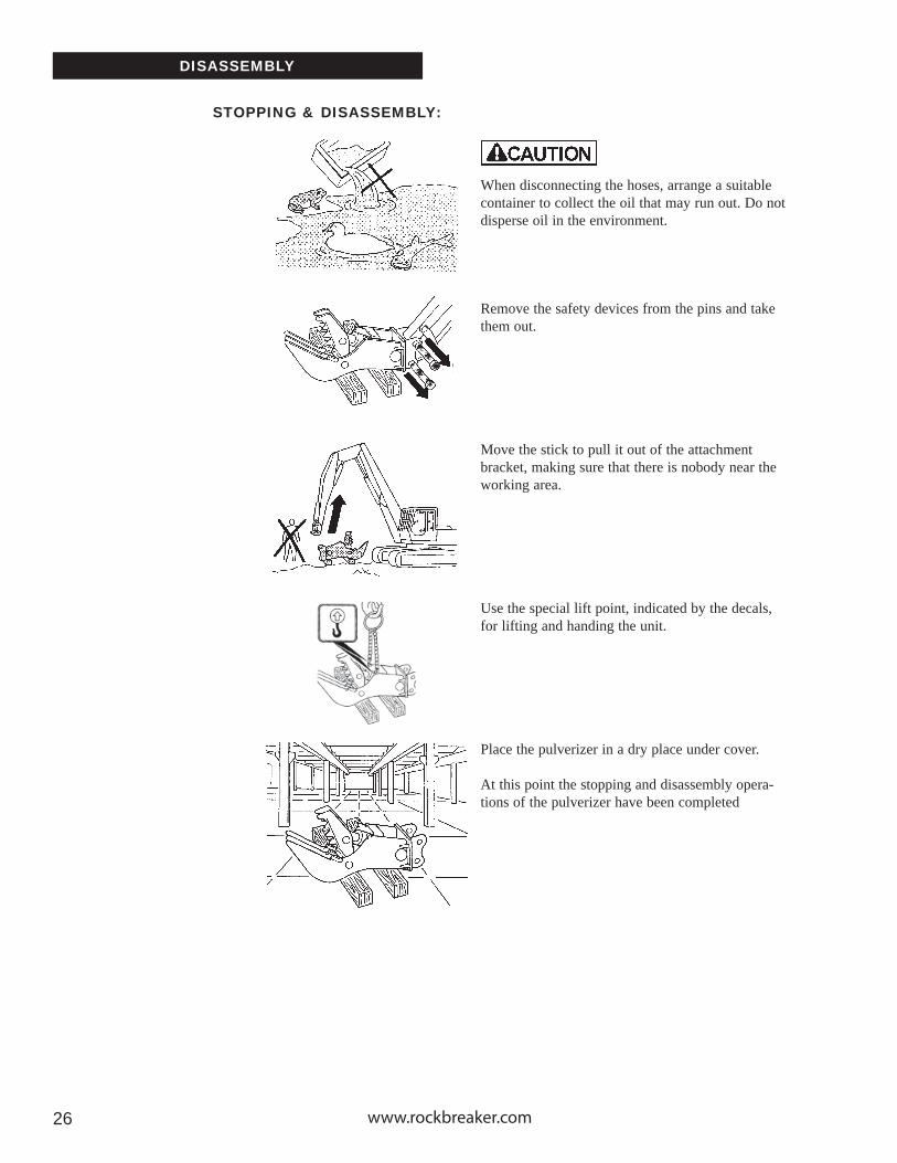
When disconnecting the hoses, arrange a suitable container to collect the oil that may run out. Do not disperse oil in the environment.
Remove the safety devices from the pins and take them out.
Move the stick to pull it out of the attachment bracket, making sure that there is nobody near the working area.
Use the special lift point, indicated by the decals, for lifting and handing the unit.
Place the pulverizer in a dry place under cover.
At this point the stopping and disassembly opera-tions of the pulverizer have been completed
STOPPING & DISASSEMBLY:
DISASSEMBLY

Pulverizer Owner’s Manual 2727
Place the open jaw over the material to be broken. Allow the material to enter into the jaw as far as possible.
Close the jaws allowing the teeth to penetrate the material.
Continue to close until the jaws come to a stop and will go no further.
If the unit does not break the material, open and reposition taking a smaller bite. Results can be achieved by using an "on-again off-again" action.
Once the material has broken continue working the jaw until the material has been crushed to the desired size and all reinforcing steel has been completely separated from the concrete.
Long Strains of reinforcing steel can be cut using the cutting blades installed in the throat of the crusher.
PULVERIZER OPERATION:
OPERATION
INT
RO
DU
CT
ION
SA
FET
YIN
STA
LLAT
ION
OP
ER
AT
ION
MA
INT
EN
AN
CE
WA
RR
AN
TY
PAR
TS

www.rockbreaker.com2828
MAINTENANCE
To keep your pulverizer in top operating condition, the following main-tenance must be done. Keep in mind that lubrication is the single most important procedure for sustaining the life of a pulverizer.
USE PROPER GREASEAlways use a moly-based grease, refer to accompanying chart. Never use GP (General Purpose) grease, it melts and runs down the attachment pro-viding very poor lubrication.
GREASE OFTENFailure to lubricate regularly reduces the life of the attachment, bushings and cylinders. All operation of adjustment, maintenance, repair or cleaning must be made with the motor off, with the attachment resting fi rmly on the ground , and with no residue hydraulic oil pressure. The residue pressure must be discharged by operating, the controls several times with the motor off, and de-pressurizing the oil reservoir. This intervention must be signalled by placing a notice in the cab of the carrier.

Pulverizer Owner’s Manual 2929
MAINTENANCE
INT
RO
DU
CT
ION
SA
FET
YIN
STA
LLAT
ION
OP
ER
AT
ION
MA
INT
EN
AN
CE
WA
RR
AN
TY
PAR
TS

www.rockbreaker.com3030
MAINTENANCE
GREASE SPECIFICATIONS:
Use a high performance, multipurpose, extreme pressure (EP2) lithium complex grease with molybdenum disulfi de (3 to 5%) developed to satisfy the severe lubrication requirements of off-road equipment.
These requirements will handle the toughest of lubricating jobs and last signifi cantly longer than conventional greases. Wear, galling or seizing of greased surfaces can occur even when using high performance greases. During these extreme pressure conditions, the molybdenum disulfi de par-ticles are left behind on the surface in a thin, adherent, lubricating fi lm.
This grease will have an excellent resistant to water washout in equipment operating under wet conditions and /or high temperatures and subject to heavy or shock loading.
These greases have:
High dropping point (>500 deg F or 260 deg C) High load-carrying capacity Excellent wear protection Excellent resistant to water washout Excellent resistant to separation Protects against rust and corrosion
Some examples:
Casrol Contractor Grease 2Conoco Superlube M EPExxon Centaur MolyPennzoil Multpurpose EP 302Petro Canada Precision Moly EP 2Texaco Starplex Moly MPGM2Gulfl ex Moly EP 2Chesterton 613 Moly Grease

Pulverizer Owner’s Manual 3131
MAINTENANCE
This operation should be performed by skilled personnel using a torque wrench.Check these bolts every ten successive hours. Verify that they have not slackened or show signs of damage.
The bolts may be retightened only once, after that it is recom-mend they be replaced.
ROUTINE MAINTENANCE:
After performing underwater demolition work, disassemble all of the joints. Clean the pins and bushings thoroughly and eliminate any traces of oxidation.
INT
RO
DU
CT
ION
SA
FET
YIN
STA
LLAT
ION
OP
ER
AT
ION
MA
INT
EN
AN
CE
WA
RR
AN
TY
PAR
TS
www.rockbreaker.com3232
WELD PROCEDURE FOR DILLIDUR 400V
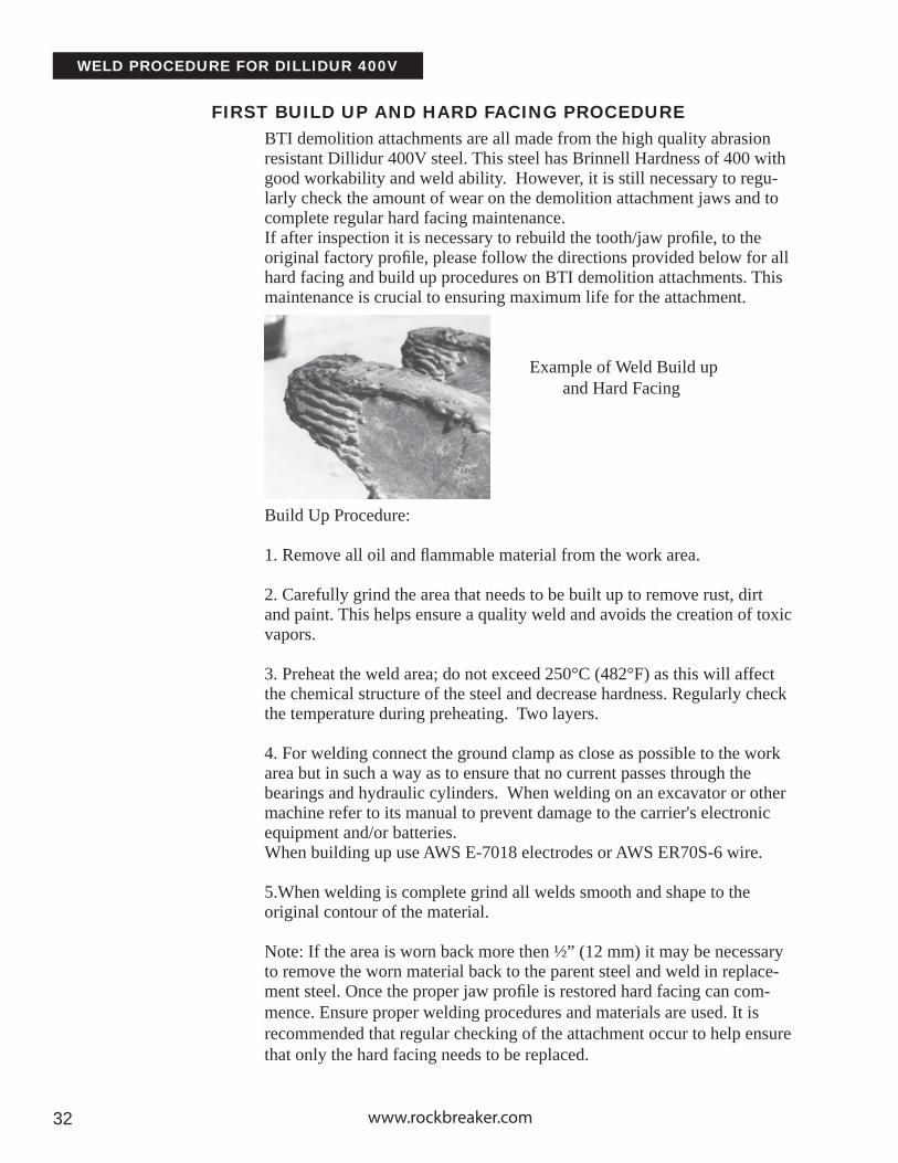
BTI demolition attachments are all made from the high quality abrasion resistant Dillidur 400V steel. This steel has Brinnell Hardness of 400 with good workability and weld ability. However, it is still necessary to regu-larly check the amount of wear on the demolition attachment jaws and to complete regular hard facing maintenance. If after inspection it is necessary to rebuild the tooth/jaw profi le, to the original factory profi le, please follow the directions provided below for all hard facing and build up procedures on BTI demolition attachments. This maintenance is crucial to ensuring maximum life for the attachment.
Build Up Procedure:
1. Remove all oil and fl ammable material from the work area.
2. Carefully grind the area that needs to be built up to remove rust, dirt and paint. This helps ensure a quality weld and avoids the creation of toxic vapors.
3. Preheat the weld area; do not exceed 250°C (482°F) as this will affect the chemical structure of the steel and decrease hardness. Regularly check the temperature during preheating. Two layers.
4. For welding connect the ground clamp as close as possible to the work area but in such a way as to ensure that no current passes through the bearings and hydraulic cylinders. When welding on an excavator or other machine refer to its manual to prevent damage to the carrier's electronic equipment and/or batteries.When building up use AWS E-7018 electrodes or AWS ER70S-6 wire.
5.When welding is complete grind all welds smooth and shape to the original contour of the material.
Note: If the area is worn back more then ½” (12 mm) it may be necessary to remove the worn material back to the parent steel and weld in replace-ment steel. Once the proper jaw profi le is restored hard facing can com-mence. Ensure proper welding procedures and materials are used. It is recommended that regular checking of the attachment occur to help ensure that only the hard facing needs to be replaced.
FIRST BUILD UP AND HARD FACING PROCEDURE
Example of Weld Build up and Hard Facing

Pulverizer Owner’s Manual 3333
WELD PROCEDURE FOR DILLIDUR 400V
HARD FACING PROCEDURE INT
RO
DU
CT
ION
SA
FET
YIN
STA
LLAT
ION
OP
ER
AT
ION
MA
INT
EN
AN
CE
WA
RR
AN
TY
PAR
TS
1. Remove all oil and fl ammable material from the work area.
2. Carefully grind the area that needs to be hard faced to remove surface irregularities and paint. This helps ensure a quality weld and avoids the creation of toxic vapors.
3. Preheat the weld area to a temperature of 150-200 °C (302-392°F) and do not exceed 250°C (482°F) as this will affect the chemical structure of the steel and reduce hardness. Regularly check the temperature during preheating.
4. For welding connect the ground clamp as close as possible to the work area but in such a way as to ensure that no current passes through the bearings and hydraulic cylinders. When welding on an excavator or other machine refer to its manual to prevent damage to the carrier's electronic equipment and/or batteries.

www.rockbreaker.com3434
WELD PROCEDURE FOR DILLIDUR 400V
Some other possible brands.

Pulverizer Owner’s Manual 35
INTERCHANGEABLE TEETH
BTI’s unique replaceable tooth design ensures maximum pen-etration and fragmentation of material, while being fast and easy to change in fi eld.Older model MCP Pulverizers with fi xed teeth can also be retrofi tted with the replaceable system, dramatically reducing downtime required for hard-facing.
Tooth Removal:-Heat epoxy material to 250 degrees.
-Using a punch and hammer, drive the lock pin out, opposite to the way it was installed.
-Inspect the adapter and lock pin for damage before installing the new tooth.
DISASSEMBLY OF INTERCHANGEABLE TEETH
INT
RO
DU
CT
ION
SA
FET
YIN
STA
LLAT
ION
OP
ER
AT
ION
MA
INT
EN
AN
CE
WA
RR
AN
TY
PAR
TS
www.rockbreaker.com36
INTERCHANGEABLE TEETH
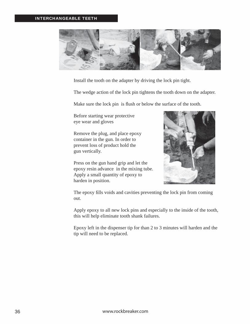
Install the tooth on the adapter by driving the lock pin tight.
The wedge action of the lock pin tightens the tooth down on the adapter.
Make sure the lock pin is fl ush or below the surface of the tooth.
Before starting wear protective eye wear and gloves
Remove the plug, and place epoxy container in the gun. In order to prevent loss of product hold the gun vertically.
Press on the gun hand grip and let the epoxy resin advance in the mixing tube. Apply a small quantity of epoxy to harden in position.
The epoxy fi lls voids and cavities preventing the lock pin from coming out.
Apply epoxy to all new lock pins and especially to the inside of the tooth, this will help eliminate tooth shank failures.
Epoxy left in the dispenser tip for than 2 to 3 minutes will harden and the tip will need to be replaced.

Pulverizer Owner’s Manual 37
WELDING OF TEETH
INT
RO
DU
CT
ION
SA
FET
YIN
STA
LLAT
ION
OP
ER
AT
ION
MA
INT
EN
AN
CE
WA
RR
AN
TY
PAR
TS

www.rockbreaker.com38
UPGRADING OLDER MCP MODELS
To install the six adapters and standard teeth on the upper (moving) jaw, prepare a place for welding the adapters by cutting out a pocket of parent steel following the diagram and dimensions shown.
Cut out a bevel of a least ½” (7mm) of the parent steel providing a deep area for weld penetration.
If the parent steel has a thickness of 1” (25mm) or less, you may need to laminate a plate to provide additional support.
Using the guide lines set out in the Weld Procedure for Dillidur 400V pro-ceed installing the teeth.

Pulverizer Owner’s Manual 39
ASSEMBLY OF TEETH
INT
RO
DU
CT
ION
SA
FET
YIN
STA
LLAT
ION
OP
ER
AT
ION
MA
INT
EN
AN
CE
WA
RR
AN
TY
PAR
TS
www.rockbreaker.com40
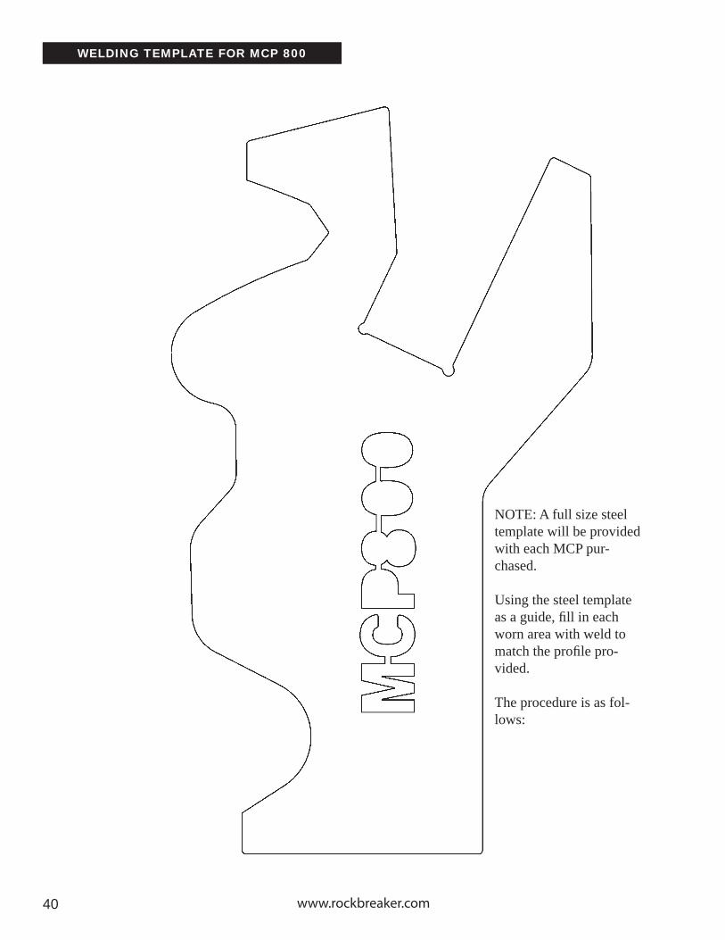
WELDING TEMPLATE FOR MCP 800
NOTE: A full size steel template will be provided with each MCP pur-chased.
Using the steel template as a guide, fi ll in each worn area with weld to match the profi le pro-vided.
The procedure is as fol-lows:

Pulverizer Owner’s Manual 41
WELDING TEMPLATE FOR MCP 800
INT
RO
DU
CT
ION
SA
FET
YIN
STA
LLAT
ION
OP
ER
AT
ION
MA
INT
EN
AN
CE
WA
RR
AN
TY
PAR
TS

www.rockbreaker.com42
WELDING TEMPLATE FOR MCP 910

Pulverizer Owner’s Manual 43
WELDING TEMPLATE FOR MCP 910
INT
RO
DU
CT
ION
SA
FET
YIN
STA
LLAT
ION
OP
ER
AT
ION
MA
INT
EN
AN
CE
WA
RR
AN
TY
PAR
TS

www.rockbreaker.com44
WELDING TEMPLATE FOR MCP 1000

Pulverizer Owner’s Manual 45
WELDING TEMPLATE FOR MCP 1000
INT
RO
DU
CT
ION
SA
FET
YIN
STA
LLAT
ION
OP
ER
AT
ION
MA
INT
EN
AN
CE
WA
RR
AN
TY
PAR
TS

www.rockbreaker.com46 www.rockbreaker.com

Pulverizer Owner’s ManualPulverizer Owner’s Manual 4747
WARRANTY
1. BREAKER TECHNOLOGY INC. Company (hereinafter referred to as "BTI")warrants this product against defects in materials and workmanship for a period oftwelve (12) months from the date of Installation. This warranty does not cover o-rings,seals, fittings, hoses, or other items considered normal wear items. These are covered by the Limited Warranty period of thirty (30) days. Warranty for propriety items such as valves, filters, installation kits, and components that are not manufactured by BTI, will be governed by the warranty terms of their manufacturer. This warranty is void if BTI's standard installation specifications and procedures are not adhered to.
2. BTI's Customer Service Department will authorize return of any defective compo-nents or sufficient evidence of such defect to a BTI warehouse. Such componentsor such evidence must clearly show that the defect was caused by faulty material or poor workmanship. Warranty claim will be accepted only if it is submitted on a proper claims form with proof of purchase and received within sixty (60) days from the date of discovery of the defect. Warranty claims will be considered only if the "Installation Notice" has been duly filled in and returned to BTI's Customer Service Department within thirty (30) days from the date of installation.
3. BTI will at it's option, repair or refurbish the defective part(s) without charge to the initial user or may elect to issue full or partial credit toward the purchase of a new part(s). The extent of credit issued, which will be in the form of a "Credit Memo", will be determined by pro-rating against the normal life of the part(s) in question.
4. BTI is not responsible for mileage, travel time, travel expenses, overtime labor, and any freight expenses required to facilitate the repair.
5. This warranty does not apply if the product has been damaged by accident, abuse, misuse, misapplication or neglect, or as a result of service, disassembly or modification, without BTI's express authorization.
6. BTI assumes no liability beyond the replacement of defective parts or materialsand/or the correction of such defective parts or materials.
7. BTI neither assumes nor authorizes any other person to assume for it any liabilityin connection with the sale of it's products other than that specifically stated herein.
8. THIS WARRANTY IS EXPRESSLY IN LIEU OF ANY AND ALL OTHER WARRANTIES. EXCEPT AS EXPRESSLY SET FORTH HEREIN, BTI MAKES NO REPRESENTATION OR WARRANTY, STATUTORY, EXPRESS OR IMPLIED, WITH RESPECT TO THE PRODUCTS MANUFACTURED AND/OR SUPPLIED BY BTI, WHETHER AS TO MERCHANTABILITY, FITNESS FOR A PARTICULAR PURPOSE OR ANY OTHER MATTER. IN NO EVENT, INCLUDING IN THE CASE OF A CLAIM OF NEGLIGENCE, SHALL BTI BE LIABLE FOR INCIDENTAL OR CONSEQUENTIAL DAMAGES.
INT
RO
DU
CT
ION
SA
FET
YIN
STA
LLAT
ION
OP
ER
AT
ION
MA
INT
EN
AN
CE
WA
RR
AN
TY
PAR
TS

www.rockbreaker.com
MCP 800 - PARTSM
CP 8
00
Pulverizer Owner’s Manual48
When ordering, give Part Number, Part Name, Model and Serial #

Pulverizer Owner’s Manual 49
MCP 800 - PARTS
Item
123
Description
MCP800 Pulverizer FrameMCP800 Jaw AssemblyMCP800 Cylinder Feed
Qty.
111
Part Number
MCP
800
When ordering, give Part Number, Part Name, Model and Serial #
INT
RO
DU
CT
ION
SA
FET
YIN
STA
LLAT
ION
OP
ER
AT
ION
MA
INT
EN
AN
CE
WA
RR
AN
TY
PAR
TS

www.rockbreaker.com50
MCP 800 PARTSM
CP 8
00 F
ram
e
When ordering, give Part Number, Part Name, Model and Serial #
MCP 800 Frame Assembly

Pulverizer Owner’s Manual 5151
MCP 800 PARTS
Item
12345678910111213141516171819202122232425
Description
CouplingPin Cover
ScrewFrameO-RingO-Ring
Pin CoverSpring washer
NutSpacer
Self-Locking NutSpring washer
ShimCutterScrew
O-RingBushingScrew
Spring washerSelf-Locking Nut
PinScrew
O-RingPin
Lubricator
Qty.
1141211441443142216161614112
Part Number
CP800STDCP800-47
54050CP80010F
8163981437
CP800-485742557022
CP800-4359062-157426
CP800-50CP800-68
5431081639950-3053141
57424-159068
CP800-405308481779
CP800-4155013
MCP
800
Fra
me
When ordering, give Part Number, Part Name, Model and Serial #
MCP 800 Frame Assembly INT
RO
DU
CT
ION
SA
FET
YIN
STA
LLAT
ION
OP
ER
AT
ION
MA
INT
EN
AN
CE
WA
RR
AN
TY
PAR
TS
www.rockbreaker.com5252
MCP 800 - PARTSM
CP 8
00 J
aw
When ordering, give Part Number, Part Name, Model and Serial #
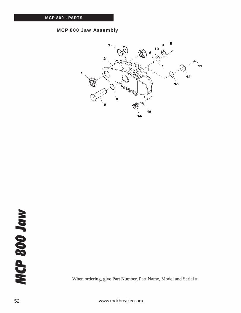
MCP 800 Jaw Assembly

Pulverizer Owner’s Manual 5353
MCP 800 - PARTS
Item
123456789101112131415
Description
BushingMoveable Frame
O-RingO-Ring
PinLockwasher
Spring WasherScrewCutterShimScrewCover
O-RingPitPin
Qty.
212114441321166
Part Number
950-30CP800-MD
8163981436
CP800-4259062-15742654310
CP800-68CP800-50
54050CP800-49
81787SP18MB
S4CA
MCP
800
Jaw
When ordering, give Part Number, Part Name, Model and Serial #
MCP 800 Jaw Assembly INT
RO
DU
CT
ION
SA
FET
YIN
STA
LLAT
ION
OP
ER
AT
ION
MA
INT
EN
AN
CE
WA
RR
AN
TY
PAR
TS

www.rockbreaker.com5454
MCP
800
Cyl
inde
r Fe
edMCP 800 - PARTS
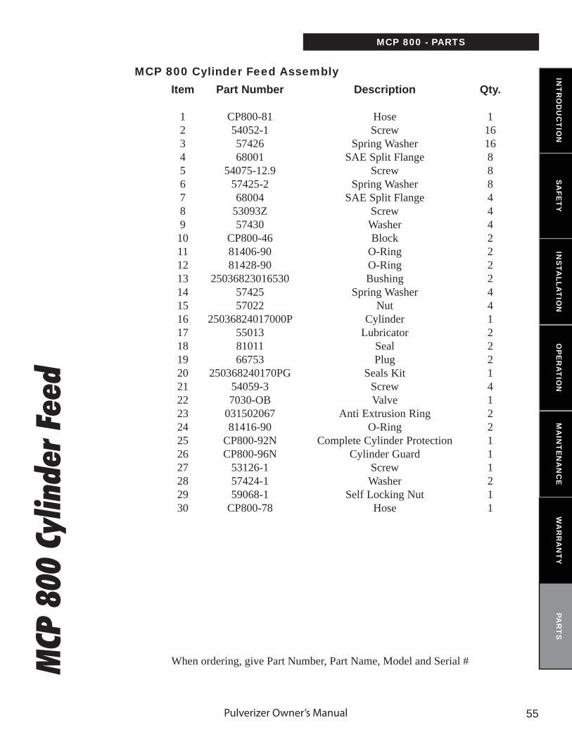
MCP 800 Cylinder Feed Assembly
When ordering, give Part Number, Part Name, Model and Serial #
Pulverizer Owner’s Manual 5555
Item
123456789101112131415161718192021222324252627282930
Description
HoseScrew
Spring WasherSAE Split Flange
ScrewSpring Washer
SAE Split FlangeScrewWasherBlock
O-RingO-RingBushing
Spring WasherNut
CylinderLubricator
SealPlug
Seals KitScrewValve
Anti Extrusion RingO-Ring
Complete Cylinder ProtectionCylinder Guard
ScrewWasher
Self Locking NutHose
Qty.
11616888444222244122214122111211
Part Number
CP800-8154052-15742668001
54075-12.957425-268004
53093Z57430
CP800-4681406-9081428-90
250368230165305742557022
25036824017000P550138101166753
250368240170PG54059-37030-OB
03150206781416-90
CP800-92NCP800-96N
53126-157424-159068-1
CP800-78
MCP 800 - PARTSM
CP 8
00 C
ylin
der
Feed
When ordering, give Part Number, Part Name, Model and Serial #
MCP 800 Cylinder Feed Assembly INT
RO
DU
CT
ION
SA
FET
YIN
STA
LLAT
ION
OP
ER
AT
ION
MA
INT
EN
AN
CE
WA
RR
AN
TY
PAR
TS

www.rockbreaker.com56

Pulverizer Owner’s Manual 57
SPEED VALVE (PART NO: 7030-OB)
INT
RO
DU
CT
ION
SA
FET
YIN
STA
LLAT
ION
OP
ER
AT
ION
MA
INT
EN
AN
CE
WA
RR
AN
TY
PAR
TS

www.rockbreaker.com5858
MCP
910
MCP 910 - PARTS
MCP 910
When ordering, give Part Number, Part Name, Model and Serial #

Pulverizer Owner’s Manual 5959
Item
123
Description
MCP910 Pulverizer FrameMCP910 Jaw AssemblyMCP910 Cylinder Feed
Qty.
111
Part Number
MCP 910 - PARTSM
CP 9
10
When ordering, give Part Number, Part Name, Model and Serial #
MCP 910 INT
RO
DU
CT
ION
SA
FET
YIN
STA
LLAT
ION
OP
ER
AT
ION
MA
INT
EN
AN
CE
WA
RR
AN
TY
PAR
TS

www.rockbreaker.com6060
MCP
910
Fra
me
MCP 910 - PARTS
MCP 910 FRAME ASSEMBLY
When ordering, give Part Number, Part Name, Model and Serial #

Pulverizer Owner’s Manual 6161
Item
12345678910111213141516171819202122232425
Description
CouplingPin Cover
Screw Max 30FrameO-RingO-Ring
Pin CoverLockwasher M16
NutSpacer
Self-Locking Nut M12Lockwasher M12
ShimCutter
Screw M12 x 60O-RingBushingScrew
Spring WasherSelf-Locking Nut
PinScrew
O-RingPin
Lubricator
Qty.
1141211441443142216161614112
Part Number
RP25STDCP910-47
54056CP9109F
8163981438
CP910-485742557022
CP910-7659062-157426
CP800-50CP800-68
5431081780
1100-3053134
57427-359071-2
CP910-405308481774
CP910-4155013
MCP 910 - PARTSM
CP 9
10 F
ram
e
When ordering, give Part Number, Part Name, Model and Serial #
MCP 910 FRAME ASSEMBLY INT
RO
DU
CT
ION
SA
FET
YIN
STA
LLAT
ION
OP
ER
AT
ION
MA
INT
EN
AN
CE
WA
RR
AN
TY
PAR
TS

www.rockbreaker.com6262
MCP
910
Jaw
MCP 910 - PARTS
MCP 910 JAW ASSEMBLY
When ordering, give Part Number, Part Name, Model and Serial #

Pulverizer Owner’s Manual 6363
Item
123456789101112131415
Description
BushingMoveable Frame
O-RingO-Ring
PinLockwasher M12
Self-Locking Nut M12ScrewCutterShim
Screw M14 x 30Cover
O-RingBitPin
Qty.
212114441321166
Part Number
1100-30CP910-MD
8163981806
CP910-4257426
59062-154310
CP800-68CP800-50
54056CP910-49
81438SP18MB1
S4CA
MCP 910 - PARTSM
CP 9
10 J
aw
When ordering, give Part Number, Part Name, Model and Serial #
MCP 910 JAW ASSEMBLY INT
RO
DU
CT
ION
SA
FET
YIN
STA
LLAT
ION
OP
ER
AT
ION
MA
INT
EN
AN
CE
WA
RR
AN
TY
PAR
TS

www.rockbreaker.com6464
MCP
910
Cyl
inde
r Fe
edMCP 910 - PARTS
MCP 910 CYLINDER FEED ASSEMBLY
When ordering, give Part Number, Part Name, Model and Serial #

Pulverizer Owner’s Manual 6565
Item
1234567891011121314151617181920212223242526
Description
HoseScrew
Lockwasher M16Semi-Flange
ScrewFlatwasher
BlockSeal
BushingLockwasher
NutHydraulic Cylinder
Grease FittingSeal Plug
Seals KitScrewValve
Anti-Extrusion RingJoint Torque
Complete Cylinder ProtectionCylinder Protection
ScrewWasher
Self Locking NutHose
Qty.
12424124424244122214122111211
Part Number
CP910-5854075-12.9
57425-268004
53093-157430
CP910-4681406-90
250540250180305742557022
25054025018000Q550138101166753
250540250180QG54059-37030-OB
03150206781416-90
CP910-90NCP910-95N
53126-157424-159068-1
CP910-58M
MCP 910 - PARTSM
CP 9
10 C
ylin
der
Feed
When ordering, give Part Number, Part Name, Model and Serial #
MCP 910 CYLINDER FEED ASSEMBLY INT
RO
DU
CT
ION
SA
FET
YIN
STA
LLAT
ION
OP
ER
AT
ION
MA
INT
EN
AN
CE
WA
RR
AN
TY
PAR
TS

www.rockbreaker.com66

Pulverizer Owner’s Manual 67
SPEED VALVE (PART NO: 7030-OB)
INT
RO
DU
CT
ION
SA
FET
YIN
STA
LLAT
ION
OP
ER
AT
ION
MA
INT
EN
AN
CE
WA
RR
AN
TY
PAR
TS

www.rockbreaker.com6868
MCP 1000 - PARTSM
CP 1
000
Pulverizer Owner’s Manual 6969
MCP 1000 - PARTS
Item
123
Description
MCP1000 Pulverizer FrameMCP1000 Jaw AssemblyMCP1000 Cylinder Feed
Qty.
111
Part Number
MCP
100
0IN
TR
OD
UC
TIO
NS
AFE
TY
INS
TALLA
TIO
NO
PE
RA
TIO
NM
AIN
TE
NA
NC
EW
AR
RA
NT
YPA
RT
S

www.rockbreaker.com7070
MCP
100
0 Fr
ame
MCP 1000 FRAME ASSEMBLY
When ordering, give Part Number, Part Name, Model and Serial #
MCP 1000 - PARTS

Pulverizer Owner’s Manual 7171
Item
12345678910111213141516171819202122232425
Description
CouplingPin Cover
Screw M16 X 45Frame O-RingO-Ring
Pin CoverLockwasher M16
NutSpacer
Self-Locking Nut M12Spring Washer M12
ShimCutter
Screw M12 X 60O-RingBushingScrew
Spring WasherSelf-Locking Nut
PinScrew
O-RingPin
Lubricator
Qty.
1141211441443142218181814112
Part Number
CP1000STDCP1000-47
54065CP10007F
8181381781
CP1000-485742557022
CP1000-7359062-157426
CP1000-50CP1000-67
5431081810
CP1000-30531315741759081
CP1000-4053091-281809
CP1000-4155013
MCP
100
0 Fr
ame
When ordering, give Part Number, Part Name, Model and Serial #
MCP 1000 FRAME ASSEMBLY
MCP 1000 - PARTS
INT
RO
DU
CT
ION
SA
FET
YIN
STA
LLAT
ION
OP
ER
AT
ION
MA
INT
EN
AN
CE
WA
RR
AN
TY
PAR
TS

www.rockbreaker.com7272
MCP
100
0 Ja
wMCP 1000 JAW ASSEMBLY
When ordering, give Part Number, Part Name, Model and Serial #
MCP 1000 - PARTS

Pulverizer Owner’s Manual 7373
Item
123456789101112131415
Description
BushingMoveable Frame
O-RingO-Ring
PinSelf Locking Nut M12
Spring Washer M12Screw M12 X 60
CutterShim
Screw M16 X 45Cover
O-RingBitPin
Qty.
212114441321166
Part Number
CP1000-30CP1000-2MD
8181081811
CP1000-4259062-15742654310
CP1000-67CP1000-50
54065CP1000-49
81796SP25MB3
S7CA
MCP
100
0 Ja
w
When ordering, give Part Number, Part Name, Model and Serial #
MCP 1000 JAW ASSEMBLY
MCP 1000 - PARTS
INT
RO
DU
CT
ION
SA
FET
YIN
STA
LLAT
ION
OP
ER
AT
ION
MA
INT
EN
AN
CE
WA
RR
AN
TY
PAR
TS
www.rockbreaker.com7474
MCP
100
0 Cy
linde
r Fe
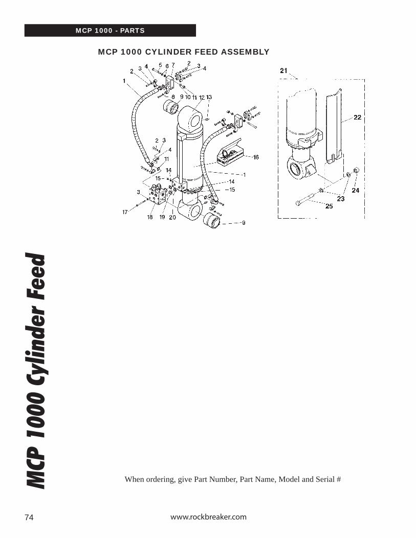
edMCP 1000 CYLINDER FEED ASSEMBLY
When ordering, give Part Number, Part Name, Model and Serial #
MCP 1000 - PARTS

Pulverizer Owner’s Manual 7575
Item
12345678910111213141516171819202122232425
Description
HoseScrew
Lockwasher M16Semi-Flange
ScrewFlatwasher
BlockSeal
BushingLockwasher M16
NutHydraulic Cylinder
Grease FittingSealPlug
Seals KitScrewValve
Anti-Extrusion RingJoint Torque
Complete Cylinder ProtectionCylinder Protection
Spring WasherSelf-Locking Nut
Screw
Qty.
2242812482424412221412211211
Part Number
CP1000-5854075-12.9
57425-268004
53093-157430
CP910-4681406-90
250595280200305742557022
25059528020000P550138101166753
250595280200NG53070-1
7030-OBM03150206781416-90
CP1000-90MCP1000-95M
57424-159068-153126-1
MCP
100
0 Cy
linde
r Fe
ed
When ordering, give Part Number, Part Name, Model and Serial #
MCP 1000 CYLINDER FEED ASSEMBLY
MCP 1000 - PARTS
INT
RO
DU
CT
ION
SA
FET
YIN
STA
LLAT
ION
OP
ER
AT
ION
MA
INT
EN
AN
CE
WA
RR
AN
TY
PAR
TS

www.rockbreaker.com7676
SPEED VALVE (PART NO: 7030-OB)

BLADE BOLT SPECIFICATIONS
Cutting BladeBolt
Specification
Bolt Type(see below)
Quanity Required
Part NumberOf The Bolt
Part Number Of The Nut
Allen WrenchSize (mm)
SpecifiedTorqueft. lbs.
MCP800
MCP900
MCP1000
CR2
CR5
CR20
CR26
CR35
SH150R
SH300R
SH401R
MP40R SJ
MP40R PJ
MP40R CJ
MP80R SJ
MP80R PJ
MP80R CJ
M12X60 CSCS
CSCSCSCS
CSCS
CSCS
CSCS
CSCS
CSCS
CSCSCSCS
CSCS
CSCS
CSCSCSCSCSCS
CSCSCSCS
CSCSCSCS
CSCSCSCS
CSCSCSCS
CSCS
SHCSSHCS
SHCS
HHB
HHB
M12X65M12X60
M12X70
M8X32
M10X40
M12X70
M16X80
M16X70
M16X70M16X80M12X30
M20X80M20X100
M20X90M20X130M20X100
M16X70M16X90M16X100
M12X80M12X70
M12X90M12X60
M20X110M20X80
M12X90
M16X110M16X70
8
44
8
4
6
6
6
8
626
74
238
622
33
44
68
8
44
9200200
93009069200200
9200208
9200017
9200174
9200004
9200208
9200406
9200506
940200192004069402005
94030019403036
940403694040219404018
9402504
9402508
94025059200208
93010069200200
94050569405017
9301006
92005609405011
9200211 M12
92002119200211
9200211
9200156
9200211
9200134
9200134
94020289402028not req’d
94030139200202
940501394050139405013
940501094050109405010
94050269405026
92002119200211
94050139405013
9405026
94050109405010
8
88
8
5
6
8
10
14
1010
19mm socket
1212
121212
1010
24mm socket
88
88
1212
8
1414
85
8585
85
25
50
85
210
210
21021085
420420
420420420
210210210
8585
8585
420420
85
210210
DEMOLITION ATTATCHMENTS - CUTTING BLADE BOLT SPECIFICATION & TORQUE INT
RO
DU
CT
ION
SA
FET
YIN
STA
LLAT
ION
OP
ER
AT
ION
MA
INT
EN
AN
CE
WA
RR
AN
TY
PAR
TS
77

an Astec company
RIVERSIDE FACILITY
3453 Durahart StreetRIVERSIDE, CALIFORNIA
92507 U.S.A.Phone: (951) 369-0878
Fax: (951) 369-8281
SOLON FACILITY
30625 Solon Industrial ParkwaySOLON, OHIO44139 U.S.A.
Phone: (440) 248-7168Fax: (440) 248-8645
THORNBURY FACILITY
35 Elgin StreetTHORNBURY, ONTARIO
N0H 2P0 CanadaPhone: (519) 599-2015
Fax: (519) 599-6803