Embed Size (px)
DESCRIPTION
nbnb
Citation preview
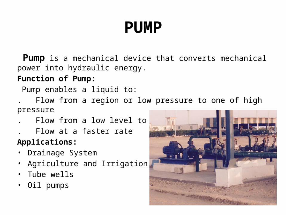
PUMP
Pump is a mechanical device that converts mechanical power into hydraulic energy.
Function of Pump:
Pump enables a liquid to:
. Flow from a region or low pressure to one of high pressure
. Flow from a low level to a higher level
. Flow at a faster rate
Applications:• Drainage System• Agriculture and Irrigation system• Tube wells• Oil pumps
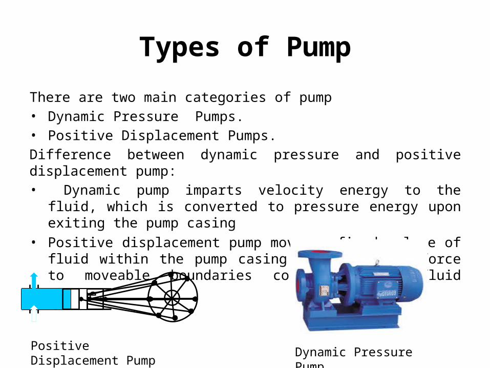
Types of Pump
There are two main categories of pump• Dynamic Pressure Pumps.• Positive Displacement Pumps.
Difference between dynamic pressure and positive displacement pump:• Dynamic pump imparts velocity energy to the fluid, which is converted to
pressure energy upon exiting the pump casing
• Positive displacement pump moves a fixed volume of fluid within the pump casing by applying a force to moveable boundaries containing the
fluid volume.
Positive Displacement Pump Dynamic Pressure Pump

Classification of Pumps
Diaphragm
Piston
Plunger
Reciprocating Rotary
Mixed flow Gear
Lobe
Sliding Vane
Screw
Axial flow
Centrifugal
Dynamic Pressure Pump
Turbine
Positive Displacement
PUMP
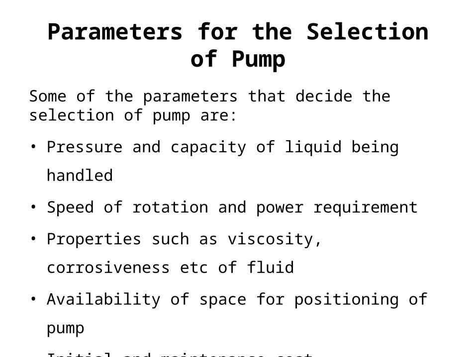
Parameters for the Selection of Pump
Some of the parameters that decide the selection of pump are:
• Pressure and capacity of liquid being handled
• Speed of rotation and power requirement
• Properties such as viscosity, corrosiveness etc of fluid
• Availability of space for positioning of pump
• Initial and maintenance cost

Parameters for the Selection of PumpParameter Centrifugal
PumpsReciprocating Pumps
Rotary Pumps
Optimum Flow and Pressure Applications
Medium/High Capacity,
Low/Medium Pressure
Low Capacity,High Pressure
Low/Medium Capacity,
Low/Medium Pressure
Maximum Flow Rate
100,000+ GPM 10,000+ GPM 10,000+ GPM
Maximum Pressure 6,000+ PSI 100,000+ PSI 4,000+ PSI
Space Considerations
Requires Less Space
Requires More Space Requires Less Space
Costs Lower InitialLower
MaintenanceHigher Power
Higher InitialHigher Maintenance
Lower Power
Lower InitialLower
MaintenanceLower Power
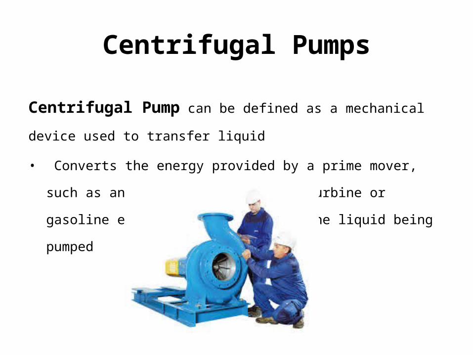
Centrifugal Pumps
Centrifugal Pump can be defined as a mechanical device used to transfer
liquid
• Converts the energy provided by a prime mover, such as an electric motor,
steam turbine or gasoline engine to energy within the liquid being pumped
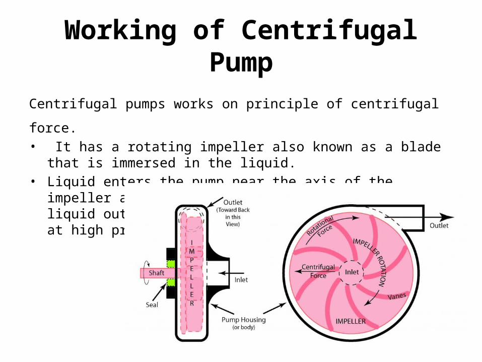
Working of Centrifugal Pump
Centrifugal pumps works on principle of centrifugal force.• It has a rotating impeller also known as a blade that is immersed in the
liquid. • Liquid enters the pump near the axis of the impeller and the rotating
impeller sweeps the liquid out toward the ends of the impeller blades at high pressure.
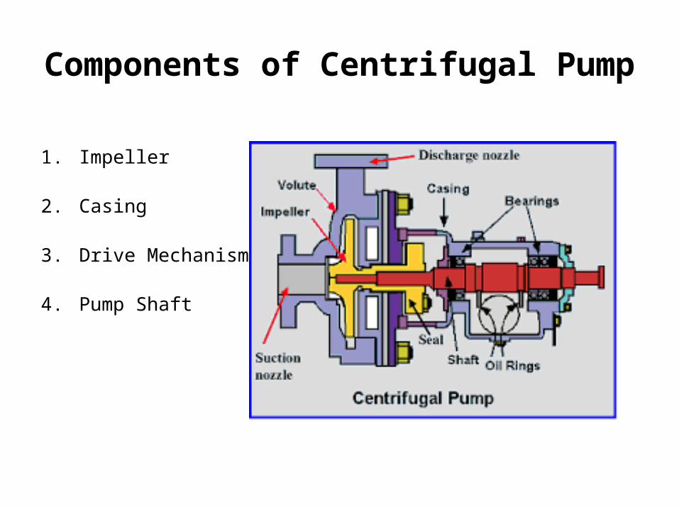
Components of Centrifugal Pump
1. Impeller
2. Casing
3. Drive Mechanism
4. Pump Shaft
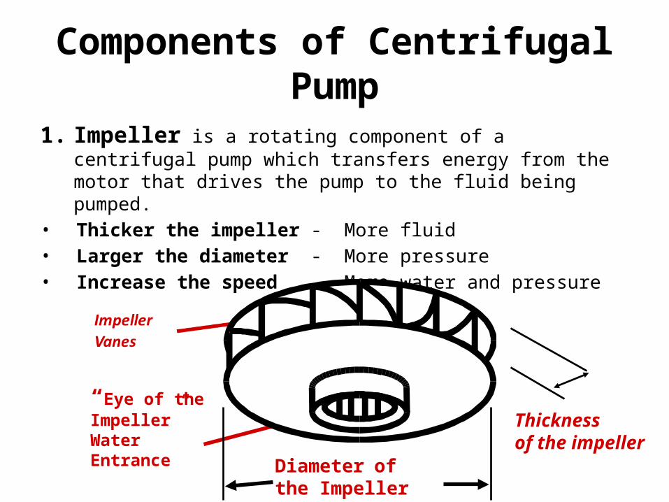
Components of Centrifugal Pump
1. Impeller is a rotating component of a centrifugal pump which transfers energy from the motor that drives the pump to the fluid being pumped.
• Thicker the impeller - More fluid• Larger the diameter - More pressure• Increase the speed - More water and pressure
“Eye of the Impeller”Water Entrance
Diameter of the Impeller
Thickness of the impeller
Components of Pump
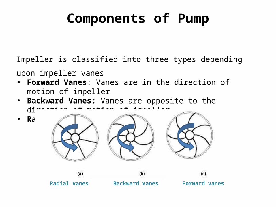
Impeller is classified into three types depending upon impeller vanes• Forward Vanes: Vanes are in the direction of motion of impeller• Backward Vanes: Vanes are opposite to the direction of motion of
impeller• Radial Vanes: Vanes are straight
Radial vanes Backward vanes Forward vanes
Components of Centrifugal Pump
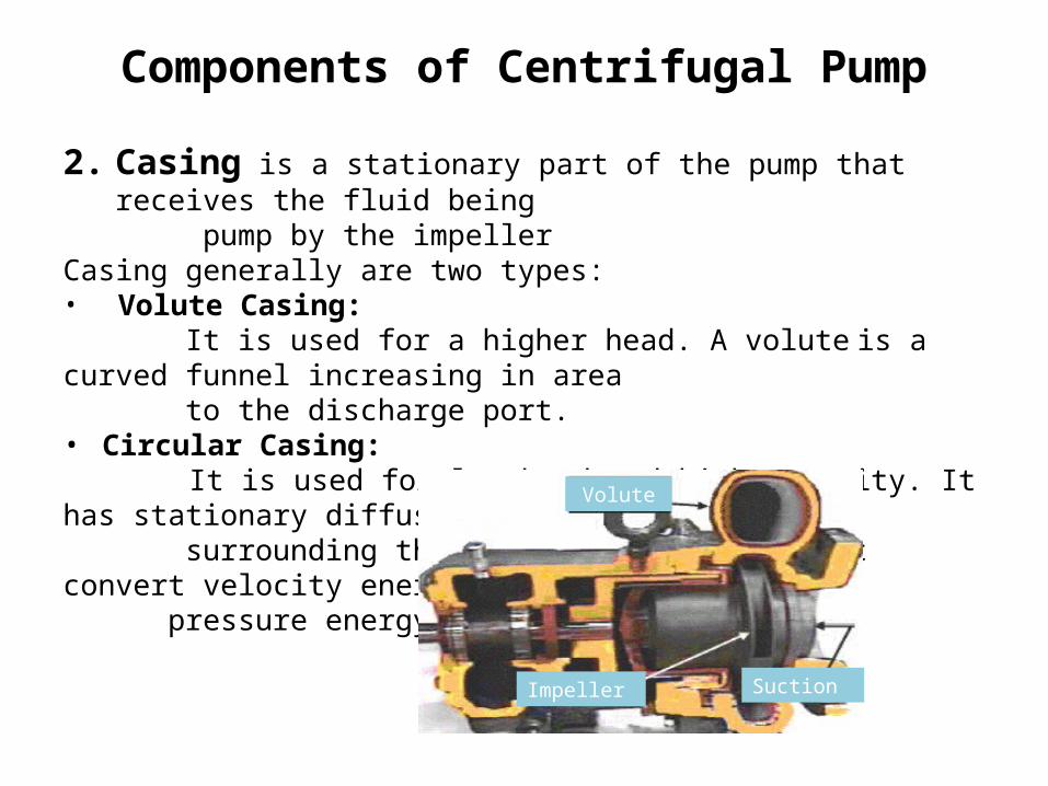
2. Casing is a stationary part of the pump that receives the fluid being pump by the impellerCasing generally are two types:• Volute Casing: It is used for a higher head. A volute is a curved funnel increasing in area to the discharge port.• Circular Casing: It is used for low head and high capacity. It has stationary diffusion vanes surrounding the impeller periphery that convert velocity energy to pressure energy. Volute
SuctionImpeller
Components of Centrifugal Pump
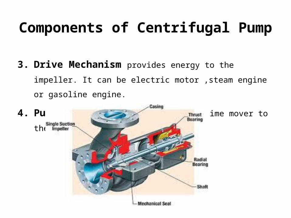
3. Drive Mechanism provides energy to the impeller. It can be electric
motor ,steam engine or gasoline engine.
4. Pump Shaft transmits power from prime mover to the pump impeller.
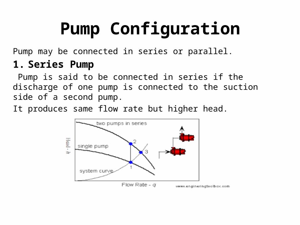
Pump ConfigurationPump may be connected in series or parallel.
1. Series Pump Pump is said to be connected in series if the discharge of one pump is connected to the suction side of a second pump.
It produces same flow rate but higher head.
Pump Configuration
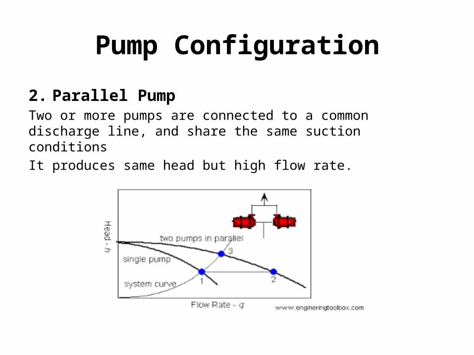
2. Parallel PumpTwo or more pumps are connected to a common discharge line, and share the same suction conditions
It produces same head but high flow rate.
Affinity Law
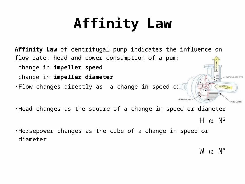
Affinity Law of centrifugal pump indicates the influence on flow rate, head
and power consumption of a pump due to:
change in impeller speed
change in impeller diameter
• Flow changes directly as a change in speed or diameter
Q a N• Head changes as the square of a change in speed or diameter
H a N2
• Horsepower changes as the cube of a change in speed or diameter
W a N3
Performance Characteristic Curve
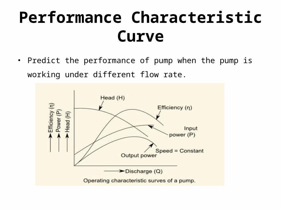
• Predict the performance of pump when the pump is working under
different flow rate.
Terminologies Used in Pump
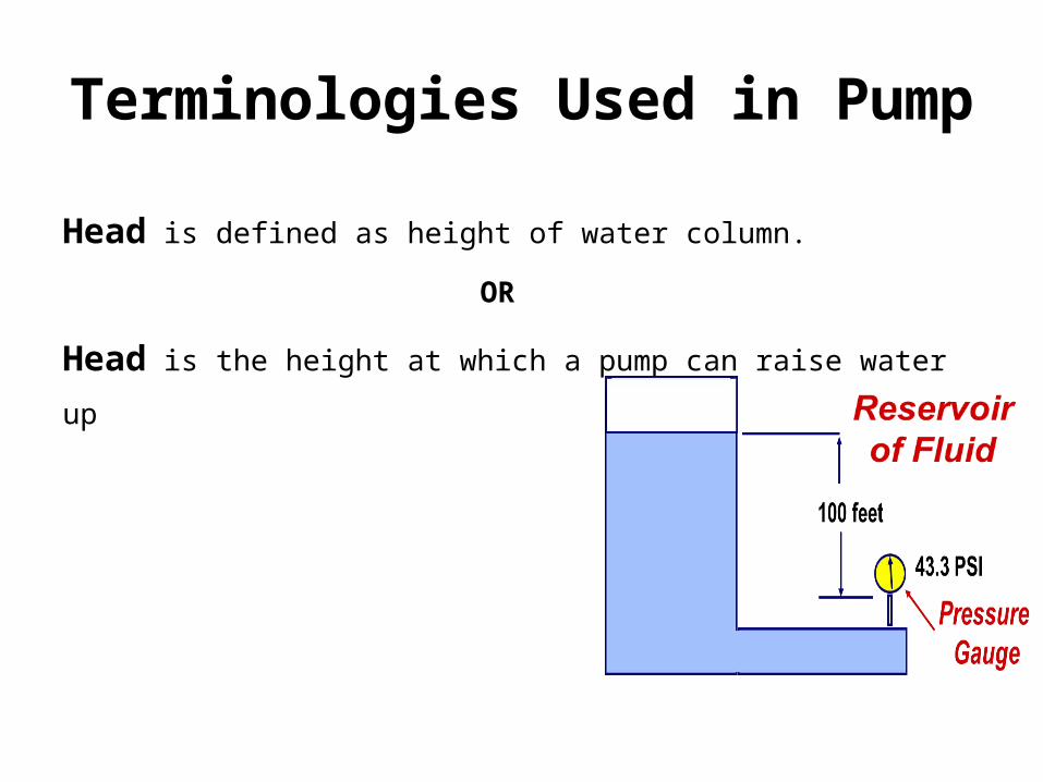
Head is defined as height of water column.
OR
Head is the height at which a pump can raise water up
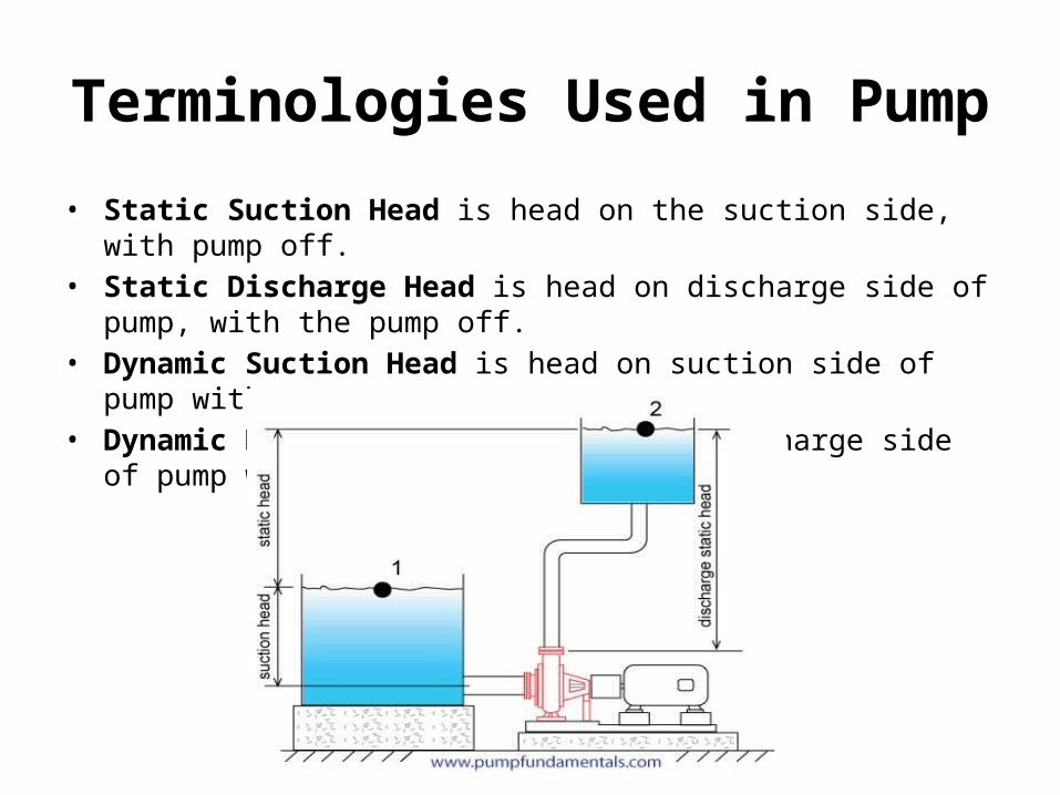
Terminologies Used in Pump
• Static Suction Head is head on the suction side, with pump off.• Static Discharge Head is head on discharge side of pump, with the pump
off.• Dynamic Suction Head is head on suction side of pump with pump on.• Dynamic Discharge Head is head on discharge side of pump with pump
on.

Terminologies Used in Pump
• Pressure Head is measure of fluid’s potential energy.
• Velocity Head is measure of fluid’s kinetic energy.
• Friction Head is measure of energy loss that heats fluid.
• Net Positive Suction Head (NPSH) defines the pressure required at the
suction of a pump to prevent cavitation
• Manometric Head is defined as the change in total energy head produced
by the pump when fluid moves through it.
Losses and Efficiencies
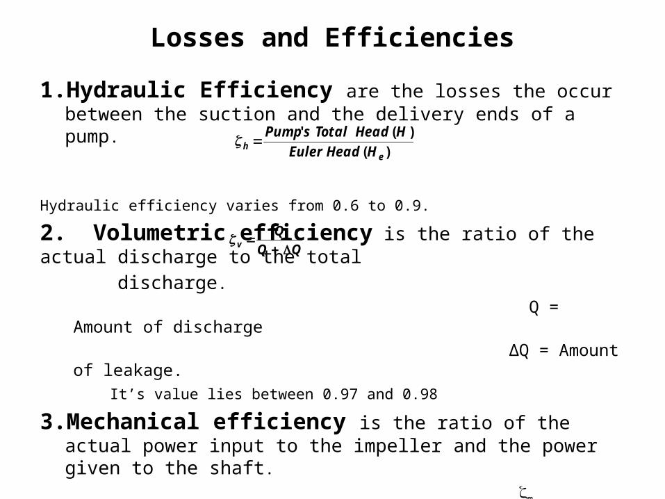
1. Hydraulic Efficiency are the losses the occur between the suction and the delivery ends of a pump.
Hydraulic efficiency varies from 0.6 to 0.9.
2. Volumetric efficiency is the ratio of the actual discharge to the total
discharge. Q = Amount of discharge
∆Q = Amount of leakage.
It’s value lies between 0.97 and 0.98
3. Mechanical efficiency is the ratio of the actual power input to the impeller and the power given to the shaft.
m P = Total power input to the shaft
∆ P = Mechanical losses
It’s value lies between 95% - 98%.
)(
)('
eh HHeadEuler
HHeadTotalsPump
Qv
Losses and Efficiencies
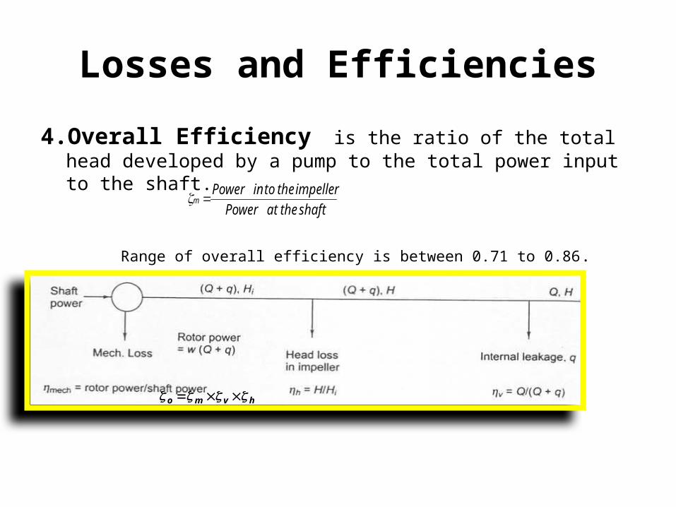
4. Overall Efficiency is the ratio of the total head developed by a pump to the total power input to the shaft.
Range of overall efficiency is between 0.71 to 0.86.
shafttheatPower
impellerthetoinPowerm
hvmo
Sizing of Pump
To size a pump, you must define:• Flow rate of liquid the pump is required to deliver• Total differential head the pump must generate to deliver the required flow
rate
• Flow RateDetermined by the process in which the pump is installed.
Defined by the mass and energy balance of the process.
• Total Differential HeadThe total differential head is made up of 2 components.
Total differential head = static head difference + frictional head losses
Sizing of Pump
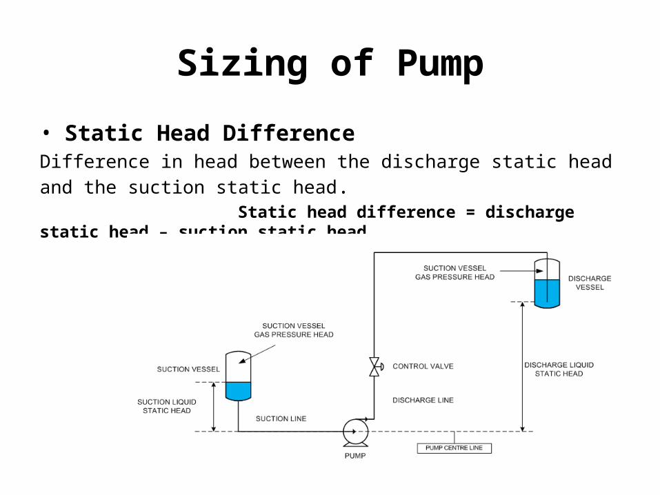
• Static Head DifferenceDifference in head between the discharge static head and the suction static
head. Static head difference = discharge static head – suction static head

Sizing of Pump
• Suction Static HeadThe suction static head is sum of the gas pressure at the surface of the liquid in the suction vessel and the difference in elevation between the surface of the liquid in the suction vessel and the center line of the pump.
Suction static head = Suction vessel gas pressure head + elevation of suction vessel
liquid surface – elevation of pump center line
Sizing of Pump
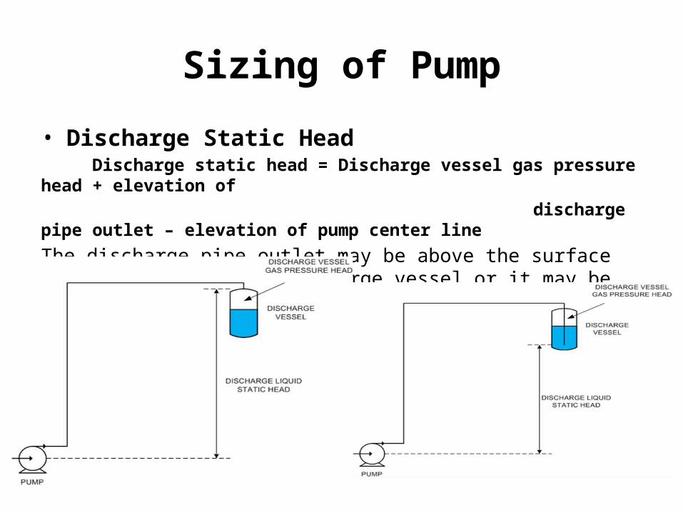
• Discharge Static Head Discharge static head = Discharge vessel gas pressure head + elevation of
discharge pipe outlet – elevation of pump center line
The discharge pipe outlet may be above the surface of the liquid in the discharge vessel or it may be submerged as shown in these two diagrams.
Sizing of Pump
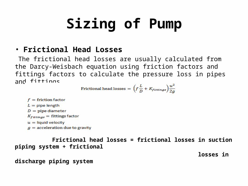
• Frictional Head Losses The frictional head losses are usually calculated from the Darcy-Weisbach equation using friction factors and fittings factors to calculate the pressure loss in pipes and fittings.
Frictional head losses = frictional losses in suction piping system + frictional
losses in discharge piping system
Sizing of Pump
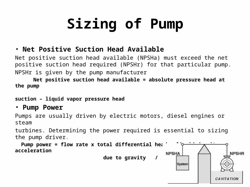
• Net Positive Suction Head AvailableNet positive suction head available (NPSHa) must exceed the net positive suction head required (NPSHr) for that particular pump.
NPSHr is given by the pump manufacturer Net positive suction head available = absolute pressure head at the pump
suction – liquid vapor pressure head
• Pump PowerPumps are usually driven by electric motors, diesel engines or steam
turbines. Determining the power required is essential to sizing the pump driver. Pump power = flow rate x total differential head x liquid density x acceleration
due to gravity / pump efficiency
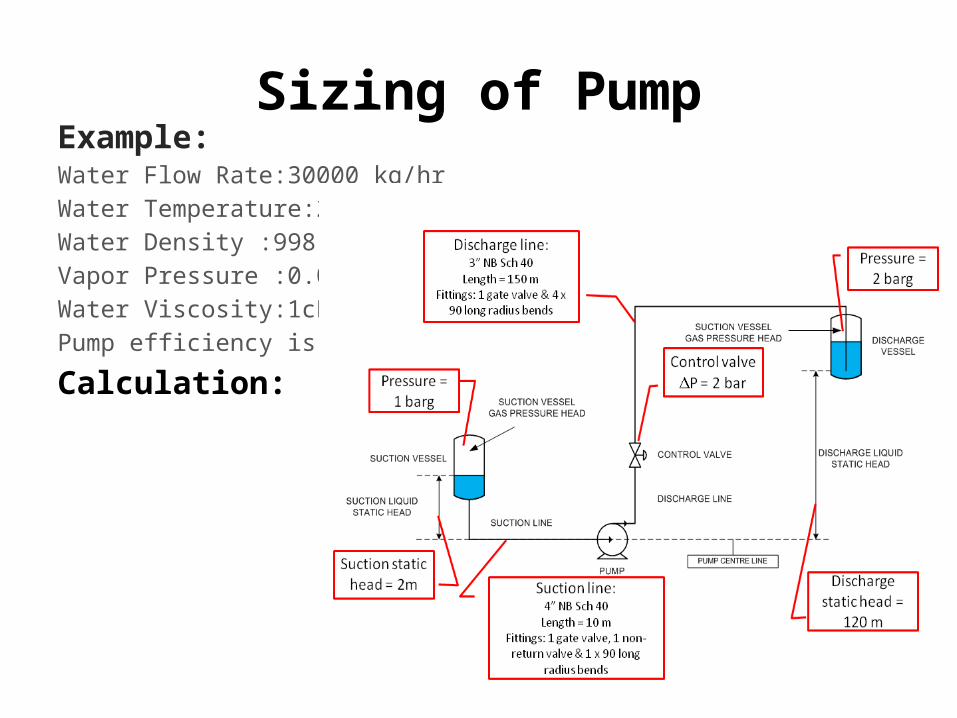
Sizing of PumpExample:Water Flow Rate:30000 kg/hr
Water Temperature:20C
Water Density :998 kg/m3
Vapor Pressure :0.023bara
Water Viscosity:1cP
Pump efficiency is 70%
Calculation:
Pump Problems and Troubleshooting
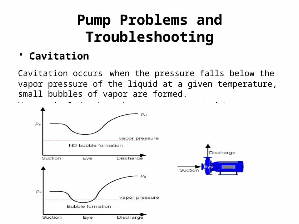
• Cavitation Cavitation occurs when the pressure falls below the vapor pressure of the liquid at a given temperature, small bubbles of vapor are formed.
Vapors implode when they are transported to an area of high pressure
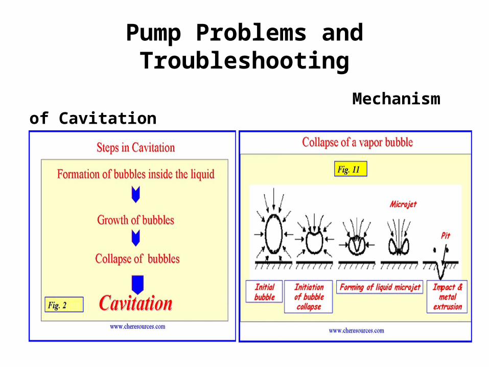
Pump Problems and Troubleshooting
Mechanism of Cavitation
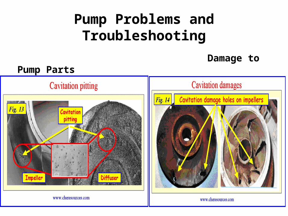
Pump Problems and Troubleshooting
Damage to Pump Parts
Pump Problems and Troubleshooting
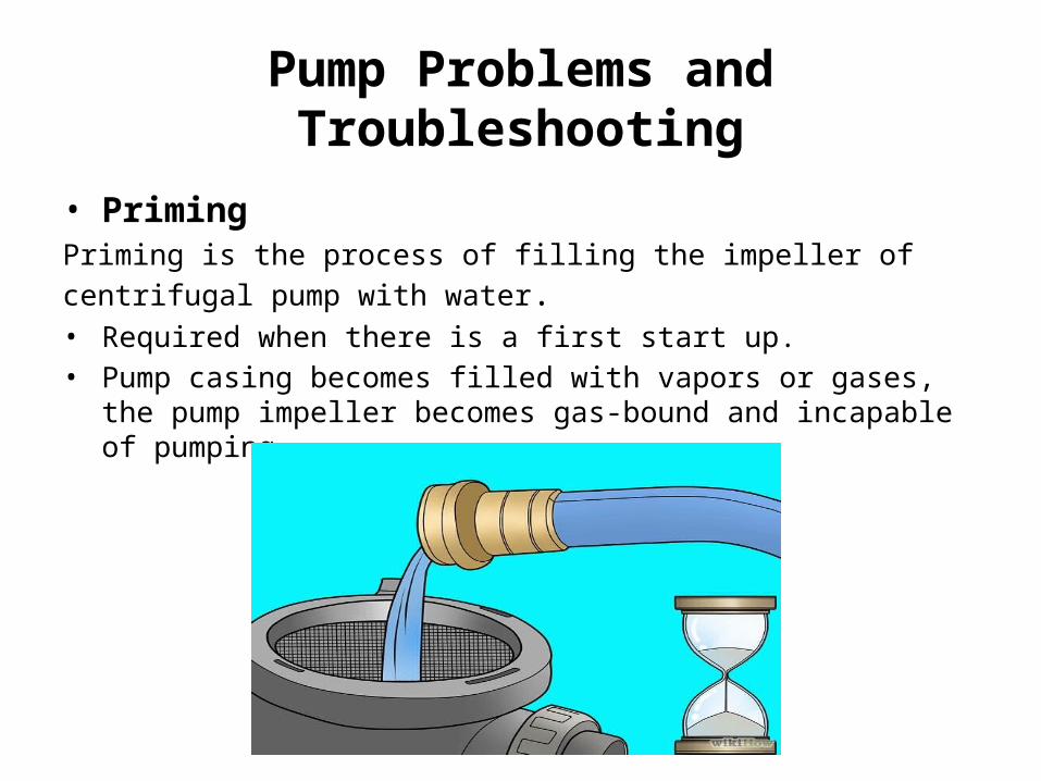
• Priming
Priming is the process of filling the impeller of centrifugal pump with water.• Required when there is a first start up.• Pump casing becomes filled with vapors or gases, the pump impeller
becomes gas-bound and incapable of pumping.

Pump Problems and Troubleshooting
References
• “Pump Wisdom” by Heinz . P . Bloch
• “Improving Pumping System Performance” A Source Book for Industry-
2nd Edition
• “Centrifugal Pump Design and Applications” 2nd Edition